1
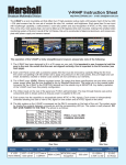
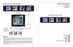
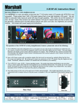
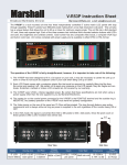
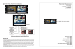
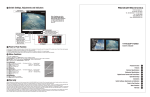
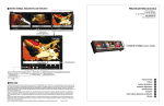
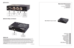
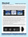
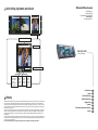
7
Switch Settings, Adjustments and Indicators
Marshall Electronics
1910 East Maple Ave.
El Segundo, CA 90245
Tel.: 800-800-6608 • Fax: 310-333-0688
www.LCDRacks.com
Email: [email protected]
Tally Indicators Illuminate when active
Dry Erase Label
V-R563P-SDI
V-R563P
-SDI
Users Guide
Image Adjustment Controls
Power On/Off switch
Illuminates red when
system power is
present
Illuminates Green
when monitor is ON
Video signal
selector
switch
Illuminates
when active
Video signal
selector
switch
Illuminates
when active
Color Bar
On/Off
switch
Illuminates
when bars
are active
Product Overview
Features
8
Warranty
Marshall Electronics warranties to the first consumer, that this V-R563P-SDI Triple 5.6 inch LCD rack mounted monitor set will, under normal use,
be free from defects in workmanship and materials, when received in its original container, for a period of one year from the purchase date.
This warranty is extended to the purchasing end user only and proof of purchase is necessary to honor the warranty. If there is no proof of
purchase provided with a warranty claim, Marshall Electronics reserves the right not to honor the warranty set forth above. Therefore, labor
and parts may be charged to you.
This warranty does not apply to product exterior and cosmetics. Misuse, abnormal service or handling, improper alterations or modifications
in design or construction, voids this warranty. No sales personnel of the seller, nor any other person is authorized to make any warranties
other than those described above, or to extend the duration of any warranties on behalf of Marshall Electronics, beyond the time period
described above.
An extra note about LCD displays: It is considered normal for a minimal amount of pixels, not to exceed three, to fail on the periphery of the
display active viewing area. Marshall Electronics has the option to reserve service for display pixel failure if deemed unobtrusive to effective
use of the monitor by our technicians.
Due to constant effort to improve products and product features, specifications may change without notice.
Electrical Specifications
Mechanical Specifications
Operational Setup
Connectors
Switch Settings, Adjustments and Indicators
Warranty
1
2
3
4
5
6
7
8
1
Product Overview
5
The V-R563P-SDI has three independently controlled 5.6” active matrix LCD monitors. Each of the 5.6” panels
produces high-resolution images with 960 x 234 pixels. The V-R563P-SDI also has a unique feature that allows the
unit to tilt up or down for optimum viewing angle and installs into an EIA standard 19” rack. Each screen has one
composite video with active loop through and one SDI (SMTPE 259M) input with active loop through, active clock
recovery and automatic 75Ω termination. There is also a money saving Digital to Analog conversion of each SDI
signal. Every display has a built-in color bar generator, 3 Tally indicators, individual front mounted selector buttons
with LED indicators and color, tint, brightness and contrast controls. The unit includes a universal voltage power
supply and features auto recognition for NTSC or PAL signals.
2
•
•
•
•
•
•
•
•
•
•
•
•
Features
V-PS12-3.3A
Color Bar Signal
5.6” diagonal (4.46” x 3.33”) (113.3 mm x 84.7mm)
4:3
960 pixel (320dot) W x 234H × 234V (225,000 pixels)
0.118mm(W) × 0.362mm (H)
35ms typical
300 cd/m²
150:1
PAL or NTSC with automatic detection. NTSC signal complies to SMPTE RS-170M
Composite BNC 75Ω self terminating 0.7V to 1.3 V P-P.
SDI BNC 75Ω self terminating with 500ft equalization.
3 Color Tally (15 pin D-Sub connection)
Active Composite loop through BNC.
Reclocked SDI loop through BNC.
10 bit Analog composite conversion of SDI signal BNC
Full field SMPTE
Power required
Operating temperature
12 V D.C. from external power supply (included) max 3.0 AMP
320 F to 1100 F (00 C to 450 C)
Outputs per display
Mechanical Specification
Dimensions
V-R682P Weight
V-PS12-3.3A Power Supply Weight
2
2. After inspection, install in your desired location of a standard EIA 19-inch equipment rack. Adequate ventilation is required when installed to prevent possible damage to the V-R563P-SDI internal components.
3. Connect required cables for signal input and output.
Please note that power must be applied to the V-R563P-SDI for all outputs to be activated.
All BNC connectors should be rated for 75Ω.
5. Attach twist lock power connection from V-PS12-3.3A power supply to the back of the unit.
6. Turn on the V-R563P-SDI by depressing the power switch located on the front of the unit.
6
Connectors
* Tally lamps active when connected to ground
Electrical Specifications
Display (Viewing Area)
Screen Aspect
Resolution (Dots)
Dot Pitch
Pixel Response Time
Brightness (in cd/m²)
Contrast Ratio
System
Inputs per display
4
1. Unpack the V-R563P-SDI and accompanying V-PS12-3.3A power supply. Physically inspect for any damage that may have occurred during shipping. Should there be any damage, immediately contact Marshall
Electronics at 800-800-6608. If you are not located within the continental united states call +1 310-333-0606.
4. Plug the V-PS12-3.3A power supply into the A.C. source
Small Footprint – occupies only 3RU of a standard EIA 19 inch rack
Ready to mount – all brackets are factory installed
Lightweight - Save over 30 pounds when compared to similar CRT models
All adjustments and selections are readily available. No menus!
Easy to use front panel selection of inputs
NTSC or Pal operation with automatic signal format detection
Switched A/B Composite inputs with active loop out
All inputs automatically terminate
Built in color bar generator for each display
Includes V-PS12-3.3A Universal power supply (U.L. class 2)
Unique 180 degree tilt adjustment
Dry erase label for each screen
3
Operational Setup
Monitor 3
Composite
Video In
Monitor 3
SDI In
Active
Output
Monitor 2
Composite
Video In
Analog
Output
converted
from SDI
Input
Monitor 2
SDI In
Active
Output
Analog
Output
converted
from SDI
Input
Monitor 1
Composite
Video In
Active
Output
Monitor 1
SDI In
Analog
Output
converted
from SDI
Input
Tally IN
DB-15 Female
Pin1-M3Grn
Pin2-M3Red
Pin3-M3Yel
Pin4-Gnd
Pin5-Gnd
Pin6-M2Grn
Pin7-M2Red
Pin8-M2Yel
Pin9-Gnd
Pin10-Gnd
Pin11-M1Grn
Pin12-M2Red
Pin13-M3Yel
Pin14-GndPin15-Gnd
12 VDC from
V-PS12-3.3A
power supply
Left Pin - Pos
Right Pin- Neg
* Composite Video Inputs comply to SMPTE-170M
* SDI inputs comply to SMPTE259M / ITU-R BT601
* Composite Video and SDI Outputs Require Power to be applied for activation
19.125”W x 2.5”D x 5.25”H (120cm x 93cm x 25cm)
5.0 lbs (2.27kg)
1 lbs (0.454kg)
V-R563P-SDI Users Guide
Marshall Electronics
3