1
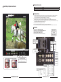
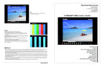
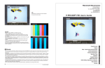
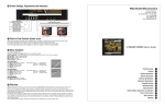
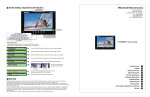
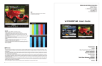
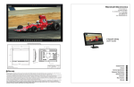
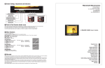
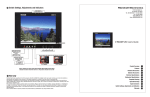
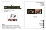
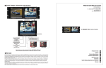
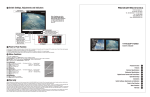
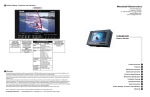
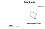
Marshall Electronics
SDI: 525i/60hz 4x3
OSD
1910 East Maple Ave.
El Segundo, CA 90245
Tel.: 800-800-6608 • 310-333-0606
Fax: 310-333-0688
www.LCDRacks.com
Email: [email protected]
Use SELECT to enable the On Screen Display
for input and function status
V-R84DP-SD Users Guide
Blue Only
SELECT to adjust SMPTE or split field color bars.
1. Allow monitor to warm up for 5-10 minutes minimum.
2. Display SMPTE color bars on monitor. Turn on off Color with control.
3. Find the PLUGE (superblack, black, and gray bars) at the lower right
of the pattern.
Adjust BRIGHTNESS until there is no difference visible between the superblack and black bars, but is still visible.
4. Adjust CONTRAST control to achieve a balanced gray scale across
top bars.
5. Turn up CHROMA (color level) control until the two outermost bars
(white and blue appear to match in brightness.
6. NTSC Only -Adjust COLOR PHASE (tint or hue) control until the third
bar from the left (cyan) and the third bar from the right (magenta) appear to
match in brightness.
Product Overview
Features
12 Warranty
Marshall Electronics warranties to the first consumer, that this V-R84DP-SD 8.4-inch TFT/LCD monitor will, under normal use, be free
from defects in workmanship and materials, when received in its original container, for a period of one year from the purchase date.
This warranty is extended to the purchasing end user only and proof of purchase is necessary to honor the warranty. If there is no proof
of purchase provided with a warranty claim, Marshall Electronics reserves the right not to honor the warranty set forth above. Therefore,
labor and parts may be charged to you.
This warranty does not apply to product exterior and cosmetics. Misuse, abnormal service or handling, improper alterations or modifications in design or construction, voids this warranty. No sales personnel of the seller, nor any other person is authorized to make any warranties other than those described above, or to extend the duration of any warranties on behalf of Marshall Electronics, beyond the time
period described above.
An extra note about LCD displays: It is considered normal for a minimal amount of pixels, not to exceed three, to fail on the periphery of
the display active viewing area. Marshall Electronics has the option to reserve service for display pixel failure if deemed unobtrusive to
effective use of the monitor by our technicians.
Due to constant effort to improve products and product features, specifications may change without notice.
8
Video - Screen Formats and Frame Rates
Electrical Specifications
Mechanical Specifications
Operational Setup
Connectors
Faceplate Cleaning
Optional Accessories
Switch Settings, Adjustments and Indicators
Menu Functions
Warranty
1
2
3
4
5
6
7
8
9
10
11
12
1 Product Overview
11 Menu Functions
The V-R84DP-SD features our Completely Digital TFT-Megapixel™ high definition TFT/LCD system with 1.44 million pixels. Analog
signals are digitized using an advanced 10 bit process with 4x over sampling and adaptive 5 line comb filter plus exacting color space
conversion. Video is scaled to fit on screen in the highest resolution using a state of the art LSI that incorporates 6x6 pixel adaptive
motion interpolation with precision Gamma correction. Additional features include Pixel-to-Pixel™ native resolution scaling, setup
memory, Underscan, H/V Delay, adjustable color temperature, and Blue Gun.
1. Power On/Off Button
2 Features
•
•
•
•
•
•
•
•
•
•
•
•
•
•
•
•
•
TFT-MegaPixel™ totally digital end to end signal processing
Multiple format acceptance for virtually any analog or digital video signal
Display PC Signals to XGA 1024x768
ColorMatch Conversion™ with SMPTE/EBU color space emulation of CRT
Color temperature preset for D65
HyperProcess™ motion interpolation of interlace images
On screen display of input status, formats, and menu functions
Pixel to Pixel™ native resolution display
Durable Metal Enclosure with protection of connections and front panel
Optical Grade Screen Cover is hardened with antiglare coating
Lightweight – 75% lighter than CRT models
Settings memory restores active state with power off/on cycle
Underscan plus H & V delay
Blue Gun for adjustment to SMPTE color bars
Includes V-PS12-5V-1 Universal power supply (U.L. class 2)
Three LEDs (Red, Green, Amber) produce 7 different tally indications on each screen
Dry erase label for each screen
3 Video - Screen Formats and Frame Rates
4 Electrical Specifications
Active Outputs
Color temperature
Color Gamut
Luma Linearity
Power Required
Power Consumption
Operating temperature
Storage temperature
Compliance
RoHS WEE / Environmental
2
2. Source Selection Buttons
Video - Composite NTSC or PAL. Composite video must comply to SMPTE-RS170M.
Images without color burst (Subcarrier) component may not display.
S-Video - Y/C (Luminance + Chrominance) NTSC or PAL
YPrPb - Analog Component color difference signals for Standard Definition (YCrCb) or High Definition (YPrPb)
VGA - Analog PC
DVI - Digital or Analog Computer or Video Signals. Includes ED-ID and SDCP for use with SDMI originated signals
SDSDI - Digital Input for Standard Definition (SDI-270Mbs)
3. Pixel to Pixel Function
As the native LCD displays of the V-R84DP-SD are 800 pixels wide by 600 pixels high, it is necessary to change the size of the image to
fill the whole screen. Pixel to Pixel mode bypasses the enlargement/shrink of this scaling function and displays the native incoming format.
For 525-NTSC/480P based images, pixel to pixel will appear as a 480hx640w (4:3 aspect) or 480hx720w (16:9 aspect).
For 625-PAL/576P based images, pixel to pixel will appear as a 576wx640h (4:3 aspect) or 576wx720h (16:9 aspect).
For 1080 line SD based images, pixel to pixel will appear as cropped 800hx600w (4:3 aspect) starting from the center of the image. 240
lines top, 240 lines bottom, 560 pixels left and 560 pixels right will be cropped.
For 720 line SD based images, pixel to pixel will appear as cropped 800Hx600h (4:3 aspect) with 60 lines from the top and 60 lines from
the bottom cropped. Horizontally, 240 pixels will be cropped from each edge.
3. Menu Enable and navigation
All signal types and frame rates are automatically detected
• 525 –60i / 625 - 50i (Interlaced NTSC/PAL)
• 480P (Progressive)
• 576P (Progressive)
• 720P-50P, 59.94P, 60P, 25P, 29.97P, 30P, 50P, 59.94P, 60P (Progressive)
• 1035i - 59.94i, 60i (Interlaced)
• 1080i x 1920 – 50i, 59.94i, 60i, 23.973P, 24P, 25P, 29.97P, 30P, 24psf, 23.97psf
Screen Aspect
Display (Viewing Area)
Viewing Angles
Resolution (RGB Dots)
Color Depth
Dot Pitch
Contrast Ratio
Pixel Response
Brightness (in cd/m²)
Backlight
LCD Screen Treatments
Estimated MTBF
System
Inputs
Illuminates Red when system power is present. Illuminates Green when monitor is ON.
4:3/16:9 switchable
8.4 Inch diagonal (170.4mm w x 127.8mm h)
130° H x 120° V
800H×RGBx600V (1.44 million pixels)
262,000 Colors (6-Bit)
.213mm square pixel
500:1
10ms rise/25ms fall
500 cd/m²
Field Replaceable CCFL (50,000 hour half life)
Anti Reflection, Anti Glare, Hardcoat
5 years of 24/7/365 operation
NTSC/PAL with auto recognition
DI (SMPTE259M) (ITR-U601) per screen (BNC)
YPrPb Component (3 BNC)
Composite Video PAL/NTSC auto detect (BNC)
S-Video (Y/C) (4 Pin Mini Din female)
XGA 15Pin SD-15 Female
DVI 27 (Pin DVI-I Female)
Tally (SD-15 Female)
SDSDI/SDI (SMPTE259M, 292M) (ITR-U601) per screen (BNC)
YPrPb Component (3 BNC)
Composite Video PAL/NTSC auto detect
D65 and User Adjustment
SMPTE-C/EBU 80% CIE
Typical +/- 3% with 5 IRE increments (0 to 10 IRE)
10.4 to 16.8 VDC
Approx. 40 watt nominal
32° F to 120° F (0° C to 50° C)
-4° F to 120° F (-20° C to 50° C)
₠, FCC-Class A, ANSI-63.4 (Certificates on file)
Access menu functions by selecting the MENU button. Use UP / DOWN to navigate and
SELECT to enable or disable the function
Note: Source selection is disabled when in menu mode.
Color Temperature
D-65 (6500K) - Standard setting recommended by SMPTE and EBU.
Simulates normal daylight conditions.
USER - When activated manual adjustment is performed by selecting
Adj. Color Gain or Adj. Color Bias
When in adjust mode use UP/DOWN to change values. Use SELECT to cycle RED, GREEN,
and BLUE mode. Exit to the main menu by pressing MENU.
Left Line= Increase of Gain
Center Line = D65 (Default)
Right Line = Decrease of Gain
Right Line= Increase of Bias
Center Line = D65 (Default)
Left Line = Decrease of Bias
Level Set-up
SELECT between 7.5 IRE for NTSC signals and 0 IRE for NTSC Japan and PAL signals.
7.5 mode will enable a digital black offset of the onscreen images for improved Blacks.
Color Bar
Use to SELECT internal test signal of full field color bars that is available for confirmation
of LCD operation. This function will disable input selection until cycled off.
H/V Delay
Use to SELECT display of horizontal and vertical blanking areas.
Not available for all signal types.
Under Scan
Use SELECT to reduce the display area with expansion beyond active video. Note that the
V-R102DP-SD is factory adjusted to display 100% of active video in standard display mode.
This function is normally used with analog Standard definition signals. SDI signals will display all video with ancillary data appearing to the right of the image.
Do not dispose. Return to Manufacturer or Authorized Recycle Facility
V-R84DP-SD Users Guide
Marshall Electronics
7
5 Mechanical Specifications
10 Switch Settings, Adjustments and Indicators
Dimensions
V-R84DP-SD Weight
V-PS12-5V-1 Power Supply Weight
10.25”w x 7” h x 2.5” d (260.4mm x 215.9mm x 38.1mm)
4 lbs (1.8 kg)
1 lbs (0.45kg)
6 Operational Setup
Tally Lamps
1. Unpack the V-R84DP-SD and accompanying V-PS12-5V-1 power supply. Physically inspect for any damage that may have
occurred during shipping. Should there be any damage, immediately contact Marshall Electronics at 800-800-6608.
If you are not located within the continental United States call +1 310-333-0606.
2. After inspection, install in your desired location of a standard EIA 19-inch equipment rack.
Adequate ventilation is required when installed to prevent possible damage to the V-R84DP-SD internal components.
3. Connect required cables for signal input and output. Please note that power must be applied to the V-R84DP-SD for all outputs
to be activated. All BNC connectors should be rated for 75Ω.
4. Plug the V-PS12-5V-1 power supply into the A.C. source
5. Attach twist lock power connection from V-PS12-5V-1 power supply to the back of the unit.
6. Turn on each of the V-R84DP-SD screens by depressing the power switch located on the front of the unit for each screen.
7 Connectors
* SDI Inputs comply to SMPTE-259M,SDI-270Mbs
* Component Inputs comply to SMPTE274M, 294M, 295M, 296M
* Composite Video Inputs comply to SMPTE-170M
* Tally lamps active when connected to ground
* Battery and External Power can not be used simultaneously
Active Outputs require
power to be applied
All input signals appear as
output signal
Analog output signals are
buffered and amplified
V-Mount Battery Adapter
See Optional Accessory
section for a selection of
batteries
Dry Erase
Screen aspect ratio switch 4:3 or 16:9 selector and indicators
Tally IN
DB-15 Female
Pin1-Yel
Pin2-Red
Pin3-Grn
Pin4Pin5-Gnd
Pin6Pin7-
12 VDC from
V-PS12-5V-1 power supply
Pin 1 - Neg
Pin 2 - Pos
Pin9Pin10Pin11Pin12Pin13Pin14Pin15-Gnd
S-Video Out
4 Pin Din (Female)
Pin1 - GND
Pin2 - GND
Pin3 - Yout
Pin4 - Cout
Image Adjustment Controls
Note: Tint only functions when NTSC
Video or S-Video are selected
S-Video In
4 Pin Din (Female)
Pin1 - GND
Pin2 - GND
Pin3 - Yin
Pin4 - Cin
DVI-I Connector
4:3 Aspect
16:9 Aspect
VGA/XGA Connector
PIN#
1
2
3
4
5
6
7
8
6
V-R84DP-SD Users Guide
V-R82DP-HD
SIGNAL
RED
GREEN
BLUE
NC
GND
RED SHIELD
GREEN SHIELD
BLUE SHIELD
PIN#
9
10
11
12
13
14
15
SIGNAL
NC
NC
NC
NC
HSYNC
VSYNC
NC
Pin#
Signal
1
2
3
4
T.M.D.S
T.M.D.S
T.M.D.S
SHIELD
T.M.D.S
5
6
7
T.M.D.S DATA 4+
DDC CLOCK
DDC DATA
20
21
22
8
9
10
11
ANALOG VERT. SYNC
T.M.D.S DATA 1T.M.D.S DATA 1+
T.M.D.S DATA 1/3
SHIELD
T.M.D.S DATA 3T.M.D.S DATA 3+
+5V POWER
GND
12
13
14
15
Pin#
Signal
DATA 2DATA 2+
DATA 2/4
16
17
18
HOT PLUG DETECT
T.M.D.S DATA 0T.M.D.S DATA 0+
DATA 4-
19
23
24
T.M.D.S
SHIELD
T.M.D.S
T.M.D.S
T.M.D.S
SHIELD
T.M.D.S
T.M.D.S
C1
ANALOG RED
C2
C3
C4
C5
ANALOG
ANALOG
ANALOG
ANALOG
Marshall
MarshallElectronics
Electronics
DATA 0/5
DATA 5DATA 5+
CLOCK
CLOCK+
CLOCK-
GREEN
BLUE
HORZ SYNC
GROUND
3
Table 2 / Video Signals Displayed via DVI and YPrPb connections
(x=not available) (HDMI requires adapter to DVI)
Y Pr Pb
Input Signal Type
and aspect
DVI
SDI
4x3
16x9
4x3
16x9
720 x 486 60i
Y
Y
x
x
720 x 576 50i
Y
Y
x
x
1280 x 720 60P
Y
Y
Y
Y
Input Signal Type and aspect
4:3
16:9
NTSC (720x486i 60Hz)
Y
Y
PAL (720 x 576i 50Hz)
Y
Y
1280 x 720 50P
Y
Y
Y
Y
1280 x 720 30P
Y
Y
x
x
1280 x720 29.97P
Y
Y
x
x
1280 x720 25P
Y
Y
x
x
1280 x 720 24P
Y
Y
x
x
Input Signal Type
and aspect
1280 x 720 23.98P
Y
Y
x
x
1920 x 1080 60i
Y
Y
Y
1920x1080 59.94i
Y
Y
1920 x 1080 50i
Y
Y
1920 x 1080 30P
Y
1920x1080 29.97P
Y
1920 x 1080 25P
Y
9 Optional Accessories
Table 3 / Video Signals Displayed via SDI
DVI-D
VGA
16x9
4x3
16x9
640 x 480 60Hz
Y
Y
Y
Y
Y
640 x 480 75Hz
Y
Y
Y
Y
Y
Y
640 x 480 85Hz
Y
Y
Y
Y
Y
Y
800 x 600 60Hz
Y
Y
Y
Y
Y
Y
Y
800 x 600 75Hz
Y
Y
Y
Y
Y
Y
Y
800 x 600 85Hz
Y
Y
Y
Y
Y
1024 x 768 60Hz
Y
Y
Y
Y
Y
V-H900
Use for viewing in bright lighting or outdoors
Power Adapter Cable
V-PAC-D
Use with Anton Bauer D-type connection
Power Adapter Cable
V-PAC-XLR
Use with 4 Pin XLR connections
Battery Adapter
V-DV-PWR1
Uses 2 Sony DVCam/HDV FP-Type batteries.
When used with monitor power supply, can
charge batteries plus operate monitor
V-mount to Anton Bauer
adapter
V-ABA-01
Use to power Marshall Electronics monitors
that have V-Mount plate with Anton Bauer Gold
Mount battery.
Sequential 2 channel
charger
IDX-VL-2Plus
2-channel sequential charger with a built-in 60W
power supply. Charges 2 ENDURA E series batteries in fewer than 5 hours. One 10’ XLR cable
included. Weighs only 2 lbs
Sequential 4 channel
charger
IDX-VL-4
Economically charges 4 ENDURA E series batteries in under 6 hours using Full Power Charge
(FPC) method
Simultaneous 4 channel
charger
IDX-VL-4S
Charges 4 ENDURA E series batteries in 2.5
hours or less
55 W Lithium Battery
IDX-E7S
V-Mount battery pack with 3 LED power Indicator
55 W Lithium Battery
with Power Link
IDX-E7
V-Mount Battery Pack with PowerLink includes
accurate Power Status Display and supports
Digi-View
82 W Lithium Battery
IDX-E10S
V-Mount battery pack with 3 LED power Indicator
82 W Lithium Battery
with Power Link
IDX-E10
V-Mount Battery Pack with PowerLink includes
accurate Power Status Display and supports
Digi-View
Digital to Analog
Converter
BC-0301-10
Converts SDI to analog Composite
Mounting Plate
VP-LCD70-TMB-02
Attaches to any side for mount to ¼-20 threaded
component
Cleaning Wipes
V-HWP-K
Package of 10 non-toxic, antistatic, alcohol and
ammonia free cleaning wipes.
Table 1 / Computer Signals Displayed via DVI and VGA connector
4x3
Y
Sun Hood
1920 x 1080 24P
Y
Y
Y
Y
1024 x 768 75Hz
Y
Y
Y
Y
1920 x 1080 24Psf
Y
Y
Y
Y
1024 x 768 85Hz
Y
Y
Y
Y
8 Faceplate Cleaning
Faceplate Cleaning
When cleaning the faceplate it is very important to use non-abrasive and ammonia free cleaning agents and a clean micro fiber cloth. Do not use paper
towels. Paper towel fibers are coarse and may scratch the surface of the Polycarbonate faceplate. Paper towels may also leave streaks on the surface.
Antistatic and fingerprint resistant cleaning agents are recommended.
Wash protective cover with a solution of mild soap or detergent and lukewarm water. Use a clean soft cloth, applying only light pressure. Rinse with clean
water and dry by blotting with a damp cloth or chamois. Grease, oil or tar may be removed with a good grade of hexane, aliphatic naphtha, or kerosene.
These solvents may be obtained at a paint or hardware store and should be used in accordance with manufacturer’s recommendations.
DO NOT USE: window cleaning sprays, kitchen scouring compounds or solvents such as acetone, gasoline, benzene, alcohol, carbon tetrachloride, or
lacquer thinner. These can scratch the sheet’s surface and/or weaken the sheet causing small surface cracks called “crazing.”
Faceplate Dusting
Dust with a soft, damp cloth or chamois. Dry or gritty cloths may cause surface scratches and create a static electric charge on the surface. Neutralizing
static electricity effects by using recommended cleaning and polishing practice.
Faceplate Polishing
Protect and maintain surface gloss by occasional polishing with a good plastic cleaner and polish. Apply a thin, even coat with a soft clean cloth and polish lightly with cotton flannel. Then wipe with a damp cloth to help eliminate electrostatic charges that can attract dust particles
Marking on the Faceplate
Use SHARPEE or equivalent marker. Clean as per instructions with an ammonia free cleaning agent.
Recommended Anti-Static Cleaners and Polishes
210 Plastic Cleaner & Polish and 210 Plus Cleaner
Exair Corporation
Plexus Plastic Cleaner
Sumner Laboratories
1250 Century Circle North
Cincinnati, OH 45246-3309
513-671-3322
Fax : 513-671-3363
www.exair.com
Plexus
186 Lincoln Street
Boston, MA 02111
617-542-8656 / Fax: 617-482-9001
638 Lindero Canyon Rd. #371
Agoura, CA 91301
800-405-6495
Fax: 818-879-0697
Crystalclean
The Simco Industrial Static Control
NOVUS #1 Plastic Clean and Shine
Discovery Plastics
An Illinois Tool Works Co.
2257 North Penn Road
Hatfield, PA 19440-1998
800-203-3419
215-822-2171
Fax: 215-822-3795
www.simco.biz
NOVUS, Inc.
3700 Western Way, NE
Millersburg, OR 97231
541-926-2900 / Fax: 541-967-8441
www.discoveryplastics.com
Scotch-Brite High Performance Cloth
20/20 Plastic-Cleaner
3M Stationery & Office Supplies Div.
3M Center
Craftics, Inc.
St. Paul, MN 55144-1000
877-362-5684
Fax: 651-733-0382
www.mmm.com
4
PO Box 91930
Albuquerque, NM 87199
(505) 338-0005
V-R84DP-SD Users Guide
12800 Highway 13 South, Suite 500
Savage, MN 55378
800-548-6872 ext.451
Fax: 952-946-0435
Marshall Electronics
5