1
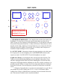
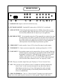
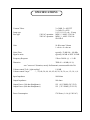
MANLEY
LABORATORIES, INC.
OWNER'S MANUAL
THE 300B
PREAMPLIFIER
MANLEY LABORATORIES, INC.
13880 MAGNOLIA AVE.
CHINO, CA. 91710
TEL: (909) 627-4256
FAX: (909) 628-2482
email: [email protected]
http://www.manleylabs.com
CONTENTS
SECTION
PAGE
INTRODUCTION
3
MAINS CONNECTIONS
4
CONNECTING YOUR PREAMPLIFIER
5
FIGURE 1
FRONTPANEL
6
FIGURE 2
TOP PANEL
7
FIGURE 3
BACK PANEL
8
OPERATIONAL NOTES
9
SPECIFICATIONS
10
WARRANTY
11
WARRANTY REGISTRATION
12
INTRODUCTION
THANK YOU!...
for choosing the Manley Laboratories "The 300B Preamplifier". Designed by David Manley, the 300B
Preamplifier uses the best available parts with the shortest, cleanest, signal path possible. This Preamp
features the 300B direct heated triode as the line and headphone driver. The 300B is typically used in
low power amplifiers as the only power tube. These amps generally deliver 5 to 9 watts single-ended and
cost from $3000 to over $100,000 Some of these amps sound very nice coupled with efficient speakers.
We build an amplifier that uses a pair of 300B's that can be operated single-ended or push-pull and
delivers up to 36 watts. We consider the 300B to be an extremely good tube for low power purposes.
Driving headphones and cables is a very good application for these tubes. Here is where the impedances
are not too low and the power requirements are not too high, however, these applications are near the
limits of where smaller triodes and dual-triodes are usable. We combine the classic 300B with another
classic - the 6SL7GT to provide the complete amplification stage. To complement this tube choice we
chose to use tube based rectification and regulation as well as our usual extreme filtering.
To complement our best sounding line driver to date, we used the techniques of the best passive
preamps. We used a 24 position gold contact Grayhill switch with metal-film 1% 1/2 watt resistors for a
superior audio attenuator and a widely separated ceramic switch for input selection. Also used were, gold
plated connectors, high purity copper wire, Mil-spec printed circuit boards with extra thick copper and
plating, and custom designed transformers.
The elegant front panel finish is a high purity plated gold that complements the electronics both visually
and in its long lasting outstanding quality. Please take a few moments to read through this manual, there
may be features and information about this preamplifier which you should familiarise yourself with.
Thank you again, and please enjoy!
GENERAL NOTES
LOCATION & VENTILATION
The Purist Preamplifier must be installed in a stable location with ample ventilation. It is recommended,
if this unit is rack mounted, that you allow enough clearance on the top and bottom of the preamp such
that a constant flow of air can flow through the ventilation slots. We also recommend that the
preamplifier be placed at least 10 inches away from its amplifier.
WATER & MOISTURE
As with any electrical equipment, this preamplifier should not be used near water or moisture.
SERVICING
The user should not attempt to service the preamplifier beyond that described in the owner's manual.
Refer all servicing other than tube replacement to Manley Laboratories.
SPECIAL NOTES
The 300B's are packaged separatly to prevent damage. You will need to carefully plug them in before
powering the preamp. Pay attention to the size of the pins to properly align the tubes before inserting.
The large pins go into the large sockets. It is difficult but possible to insert the 300B's wrong and damage
the preamp. Tubes may become loose during transit. Straighten and press down each tube before
plugging the preamplifier into the mains socket. Furthermore, do not touch the tubes after the
preamplifier has been switched on, as the tubes do become very hot during operation and should only be
handled after the power has been turned off and the tubes have cooled.
MAINS CONNECTIONS
Your preamplifier has been factory set to the correct mains voltage for your country. The
voltage setting is marked on the serial badge, located on the rear panel. Check that this complies with your local supply.
Export units for certain markets have a moulded mains plug fitted to comply with local requirements. If your unit does not have a plug fitted the coloured wires should be connected to the
appropriate plug terminals in accordance with the following code.
GREEN/YELLOW
BLUE
BROWN
EARTH
NEUTRAL
LIVE
terminal
terminal
terminal
As the colours of the wires in the mains lead may not correspond with the coloured marking
identifying the terminals in your plug proceed as follows;
The wire which is coloured GREEN/YELLOW must be connected to the terminal in the plug
which is marked by the letter E or by the safety earth symbol or coloured GREEN or GREEN
and YELLOW.
The wire which is coloured BLUE must be connected to the terminal in the plug which is
marked by the letter N or coloured BLACK.
The wire which is coloured BROWN must be connected to the terminal in the plug which is
marked by the letter L or coloured RED.
DO NOT CONNECT/SWITCH ON THE MAINS SUPPLY UNTIL ALL OTHER CONNECTIONS HAVE BEEN MADE.
CONNECTING YOUR PREAMPLIFIER
Setting up your preamplifier is rather easy.
1. Please refer to page 8 diagram 3 for an illustration of the back of the preamplifier.
2. There are two pairs of UNBALANCED RCA main outputs electically identical.
Connect either (or both for bi-amping) of the RCA outputs to the input of your amplifier as
required.
3. UNBALANCED inputs are found on RCA jack inputs and can be connected to any line
level sources such as CD players, tuners or tape decks.
4. All RCA jacks are clearly labelled as to a typical function. Each input is for all intents
functionally and electronically the same only the labels are different.
5. The record output is not buffered and it is recommended that one have the tape feed
plugged into the REC OUT only when actually recording. Care should be used when
using a 3-head tape/monitor switch as this record out is not a tape loop.
6. On the left end of the back panel is a standard IEC mains connector. This should be
connected to a standard mains outlet with the supplied cable. This unit has been hardwired for the mains voltage in your country
7. Power up the preamplifier FIRST and allow it to settle for a minimum of 30 seconds
before powering up your amplifiers. Turn off your preamplifier and source components
LAST when powering down a system. This prevents amplification of turn-on transients
and other noises when powering up or turning a system off and ultimately protects the
speakers.
INPUT SELECT
VOLUME
AUX
HEADPHONES
CD
ON
LINE OUTPUT
TAPE
TUNER
OFF
HEADPHONES
VIDEO
A
B
C
D
E
F
A - INPUT SELECT - 5 Position switch for input selection. Each input is electrically
identical. The RECORD OUT directly follows this switch. There is no buffer amp to isolate
the effects of loading and cable capacitance so we recommend disconnecting any
interconnect cables from the RECORD OUT if you are not recording.
B - VOLUME - 24 Position switch with precise 2 dB steps of attenuation throughout most of
the range. The most counter-clockwise position is mute, then -70, -60, -50, -46, -44, -42, -40
etc in 2 dB steps until -10, then the next position is -6, then 0. This gives a wide range with
good resolution in the middle. The preamp has 18 dB of total voltage gain thus unity gain is
the 19th step. Left / right matching is typically within 1/10 dB at any setting.
C & D - HEADPHONE JACKS - Standard 1/4" stereo headphone jacks. The
HEADPHONE IMPEDANCE SWITCH should be set for the range that best matches your
headphones. The OUTPUT SELECT SWITCH (E) should be set to HEADPHONES. The
maximum power output primarily depends on the actual headphone impedance. Typically the
preamp can deliver 1 watt (10 volts RMS ) into 100 ohms and 1 watt (25 volts RMS) into 600
ohms. These outputs are transformer coupled so there is the highest possible isolation from
shock hazards, cable shorts, and other potential problems.
E - BACKLIT PANEL - This is the power indicator.
F - POWER SWITCH - UP is ON, Down is OFF. Because tubes require some time to warm
up there is about 10 seconds of silence followed by "not good sound" before "wow". The best
way to power up the system is sources ( CD, turntable, etc) first, then this preamp, then after
a 30 second wait - turn on the amplifiers. Wait a minute or so - then play tunes. This allows
everything to warm up. Some people hear a difference after an hour or two but it depends on
the equipment. Powering down is the opposite order - power amps first. This procedure is a
good habit to follow because it stresses the speakers and ears the least.
The power supply in this preamp is tube based which has the inherant advantage of
slow start (as the tubes warm up). This gives the least stress to the internal components.
TOP VIEW
REGULATOR
RECTIFIER
0D3
5AR4
CAUTION! TUBES RUN HOT - DO NOT TOUCH TUBES
DO NOT OPEN CHASSIS - HIGH VOLTAGES !
REFER SERVICING TO QUALIFIED TECHNICIANS
300 OHM - 4000 OHM
A
HEADPHONE
IMPEDANCE
0D3
POWER SEQUENCE : ALLOW SEVERAL MINUTES FOR WARM-UP
TURN ON SOURCES FIRST, THEN PREAMP, THEN AMPLIFIERS
TURN OFF AMPLIFIERS FIRST, THEN PREAMP, THEN SOURCES
5AR4
NOTE - PIN SIZE FOR
PROPER ORIENTATION
30 OHM - 400 OHM
LINE
DRIVER
(TO AMPS & SPEAKERS)
LINE OUTPUT
B
OUTPUT
MODE
300B
300B
LEFT
RIGHT
HEADPHONES
(MUTES LINE OP)
THE 300B PREAMPLIFIER
ALL TRIODE VACUUM TUBE AUDIO PATH
TUBE RECTIFICATION AND REGULATION
AUDIOPHILE 2dB STEPPED
ATTENUATORS
DESIGNED BY DAVID MANLEY
PREAMP
6SL7GT
6SL7GT
HANDCRAFTED IN CHINO, CALIFORNIA
A - HEADPHONE IMPEDANCE - You should set this switch to best match your
headphones. You may have to look at the specification sheet to get the value in
ohms. If using two sets of phones divide that number in 2. If you don't have this info
then pick the setting that sounds best - no harm will be done. If the phones are lower
than the switch setting, slight loss of extreme highs may occur. Expect the 300 ohm 4000 ohm setting to be louder. Electronically, we are simply either using the two
transformer output windings in series or parallel.
B - OUTPUT MODE - Determines whether the output signals go to the back panel
RCA output jacks or to the headphone jacks. In HEADPHONES mode the main
outputs are muted - In LINE OUTPUT mode the headphones are muted.
TUBE LOCATIONS - See the diagram above for the proper tube locations. The
300B's are not installed during shipping to prevent damage to these tubes. Power
should be unplugged and the tubes cool before handling them. We label the tubes
and sockets to help and so that the calibration we do will be valid in your home. It is
possible to put the 300B's in wrong. Note the two large pins and the two small pins
on the base of the tube. The two large pins go into the two large holes in each tube
socket.
Calibration ? Internally there is a trimmer for each channel to set gain. We set
each channel for 18 dB of voltage gain (1V in = 8 Vout ). The trimmer adjusts
feedback from 5 dB to 10 dB and ensures consistancy between channels and unit to
unit. This amount of feedback can be considered minimal.
REAR PANEL
A
B
C
D
E F G H I J
A - MAINS FUSE - Replace with 2A SLO-BLO fuse only.
B - IEC MAINS SOCKET - Standard IEC mains socket (120/240 VAC as indicated)
C - LINE OUTPUTS - Main left and right outputs driven by 300B's. Connect these to your
power amplifier inputs when the amps are off. These 2 pairs of outputs
are electrically identical and a bi-amp set-up is one application.
D - RECORD OUTPUT - Set at input line stage level. These normally are connected to a tape
recorders inputs. The signal is "picked off" the input selector and before
the volume control. It is a good idea to disconnect any wires connected to
these jacks when not recording to prevent losses of extra loading and
cable capacitance from affecting best performance possible.
E - VIDEO INPUT - Audio actually, from a VCR or Laser Disc player's audio outputs.
F - TUNER INPUT - Connect your tuner outputs here. Another good input for #1 VCR.
G - TAPE INPUT - Tape machine outputs can be connected here. Be very careful - If the tape
machine inputs are connected to the preamplifier TAPE OUTPUT's and
the preamp is switched to TAPE and the tape machine is set to monitor
"INPUT" or you start to record - The dreaded squeel and howl of
feedback. One quick "cure" is not to select "TAPE" on the rotary input
selector if these other conditions are met. No "tape loop" switch.
H - CD - Plug in your audio outputs from your CD player or "D to A Converter" here.
I - AUX - Plux your Aux in here -What is an Aux?. It stands for Auxilliary and basically
means "extra", so this is just an extra input for any other source that we
didn't label or you have two of. Any of the input jacks can be used with
any hi-fi RCA outputs and they are electrically identical and only differ
in how we labelled them.
J - GROUND TERMINAL - This is a "Chassis Ground" Terminal for gear that has those
single wires with a spade lug that is meant to be "tied to ground". Helps to reduce hum.
OPERATIONAL NOTES
SWITCHING ON
The power switch is located on the right hand corner of the front panel. Flip the switch up to
turn on the preamplifier and down to turn off the preamplifier.
RUNNING
It is not recommended that you leave your preamplifier permanently switched on. This only
wastes electricity and tube life. Your preamplifier has both tube and solid state rectification and
reaches peak operating condition in approximately 30 minutes.
TUBE LIFE
As with all tubes, their quality degrades with age. This is due to cathode emission, a natural
process found in all tubes. We recommend that you have your preamplifier checked every 4-5
years, depending on usage. An excessive increase in noise level can indicate the need to replace
a tube. A 300B is a long life tube.
REPLACING A TUBE OR LAMP. You may need a small Phillips screwdriver and a
replacement tube or lamp. First be sure the unit is off and remove the IEC mains cable. Let it sit
for 15 minutes to be sure all power supply capacitors are discharged otherwise one could still
get a shock even though the unit is unplugged. If you are changing a tube or lamp, be sure that it
the same number or is on the list of possible substutions. Gently wiggle the tube around while
pulling it out of the socket. Avoid bending the printed circuit board. Before putting a new tube
in, look at it. Check to see that the pins are straight and that they line up to the socket. You
should be able to gently push the tube into the socket without excessive force. If it is the
indicator lamp that needs replacing. Remove the bottom cover. Six screws near the sides hold it
in place - when these are removed, the cover should lift off. You will see what looks like a fuse
directly behind the black name panel. Gently pry the lamp out and replace it with another lamp
and not a fuse. Replace the cover before powering up the unit.
HUM This unit is meant to use the third pin of the mains as the ground reference. Many power
amps also use the third pin mains ground. Here we have a potential source of hum and what we
call ground loops. The solution is to use one of those grounds and only ONE. Use an 3 pin to 2
pin adapter for other equipment rather than breaking off a pin. Typically one power amp will be
grounded and all other 3 pin mains gear will have adapters. Sometimes the better option is to
ground the preamp and "float" the amps.
Another source of hum can be equipment stacked on top of one another. This is not a
good plan from the ventilation standpoint generally and it is likely to introduce hum, buzz or
noise into the system. Certain gear radiates magnetic fields or high frequency noise around its
chassis and other gear may be prone to receiving these fields. Distance helps greatly.
SPECIFICATIONS
Vacuum Tubes:
Lamp type
Fuse type
120VAC operation:
220VAC operation:
2 x 300B, 2 x 6SL7GT
2 x 5AR4, 2 x OD3
1/4 X 1 1/4, 12 volt, .15 amp
MDL2, 2 AMP / 250 Volt
MDL1, 1 AMP / 250 Volt
SLO-BLO
Gain
18 dB at max Volume
1 volt in = 8 volts out
Noise Floor
Signal to noise
typically -70 dB 1Hz - 100 kHz
typically 105 dB A WGT 20-20K
Frequency Response
5 Hz to 50 kHz @ +/- 1 dB
Distortion
THD+N = -80 dB (.01 %)
zero "crossover" distortion, mostly 2nd harmonic, unmeasurable after 5th
Volume control "Left / right tracking"
1/10 dB
Volume control "steps"
-∞,-70,-60,-50,-46, -44,-42,-40,-38,-36,-34, etc, -12,-10, -6, 0
Input Impedance
100 Kohm
Output Impedance
100 ohms
Output Power (100 ohm Headphones)
Output Power (600 ohm Headphones)
1W (10 V RMS) (28 V P-P)
1W ( 25 V RMS) (70 V P-P)
Power Consumption
170 Watts (1.4 A @ 120VAC)
WARRANTY
All Manley Laboratories equipment is covered by a limited warranty against defects in materials
and workmanship for a period of 90 days from date of purchase to the original purchaser only. A
further optional limited 5 year warranty is available to the original purchaser upon proper
registration of ownership within 30 days of date of first purchase.
Proper registration is made by filling out and returning to the factory the warranty card attached to
this general warranty statement, along with a copy of the original sales receipt as proof of the
original date of purchase. Only 1 card is issued with each unit, and the serial number is already
recorded on it.
If the warranty registration card has already been removed then this is not a new unit, and is
therefore not warranted by the factory. If you believe this to be a new unit then please contact the
factory with the details of purchase.
This warranty is provided by the dealer where the unit was purchased, and by Manley Laboratories,
Inc. Under the terms of the warranty defective parts will be repaired or replaced without charge,
excepting the cost of tubes. No warranty is offered on tubes, unless:
1. a Manley Laboratories preamplifier is used with a Manley Laboratories amplifier, and
2. the warranty registration card is filled out.
In such a case a 6 month warranty on tubes is available with the correct recording of the serial
number of the preamplifier on your warranty registration card.
If a Manley Laboratories product fails to meet the above warranty, then the purchaser's sole
remedy shall be to return the product to Manley Laboratories, where the defect will be repaired
without charge for parts and labour. The product will then be returned via prepaid, insured freight,
method and carrier to be determined solely by Manley Laboratories. All returns to the factory must
be in the original packing, (new packing will be supplied for no charge if needed), accompanied by
a written description of the defect, and must be shipped to Manley Laboratories via insured freight
at the customer's own expense. Charges for unauthorized service and transportation costs are not
reimbursable under this warranty, and all warrantees, express or implied, become null and void
where the product has been damaged by misuse, accident, neglect, modification, tampering or
unauthorized alteration by anyone other than Manley Laboratories.
The warrantor assumes no liability for property damage or any other incidental or consequental
damage whatsoever which may result from failure of this product. Any and all warrantees of
merchantability and fitness implied by law are limited to the duration of the expressed warranty.
All warrantees apply only to Manley Laboratories products purchased and used in the USA.
Some states do not allow limitations on how long an implied warranty lasts, so the above
limitations may not apply to you. Some states do not allow the exclusion or limitation of incidental
or consequential damges, so the above exclusion may not apply to you.
This warranty gives you specific legal rights and you may also have other rights which vary from
state to state.
WARRANTY REGISTRATION
We ask that you please fill out this registration form and send the bottom half to:
MANLEY LABORATORIES
REGISTRATION DEPARTMENT
13880 MAGNOLIA AVE.
CHINO CA, 91710
Or you may FAX this form in to: 909-628-2482
Registration entitles you to product support, full warranty benefits, and notice of product
enhancements and upgrades. You MUST complete and return the following to validate your
warranty and registration. Thank you again for choosing Manley Laboratories.
MODEL 300B PREAMP
SERIAL No.__________________
PURCHASE DATE ______________ SUPPLIER ______________________
-------------------------------------------------------------------------------------------------------PLEASE DETACH THIS PORTION AND SEND IT TO MANLEY LABORATORIES
MODEL 300B PREAMP
SERIAL No.___________________
PURCHASE DATE ______________ SUPPLIER _______________________
NAME OF OWNER _______________________________________________
ADDRESS ______________________________________________________
CITY, STATE, ZIP ________________________________________________
TELEPHONE NUMBER ___________________________________________
COMMENTS OR SUGGESTIONS?__________________________________
________________________________________________________________