1
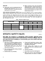
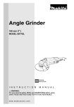
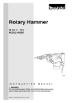
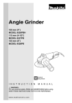
Trimmer
1/4”
MODEL 3708FC
002000
DOUBLE
INSULATION
I N S T R U C T I O N
M A N U A L
WARNING:
For your personal safety, READ and UNDERSTAND before using.
SAVE THESE INSTRUCTIONS FOR FUTURE REFERENCE.
w w w. m a k i t a t o o l s . c o m
SPECIFICATIONS
Model
3708FC
Collet chuck capacity
1/4”
No load speed (RPM)
26,000/min.
Overall length
308 mm (12-1/8”)
Net weight
1.3 kg (2.9 lbs)
• Manufacturer reserves the right to change specifications without notice.
• Specifications may differ from country to country.
GENERAL SAFETY RULES
USA002-2
(For All Tools)
WARNING:
Read and understand all instructions. Failure to follow all
instructions listed below, may result in electric shock, fire and/or
serious personal injury.
SAVE THESE INSTRUCTIONS
Work Area
Electrical Safety
1. Keep your work area clean and well lit.
Cluttered benches and dark areas invite accidents.
4. Double insulated tools are equipped with
a polarized plug (one blade is wider than
the other.) This plug will fit in a polarized
outlet only one way. If the plug does not fit
fully in the outlet, reverse the plug. If it
still does not fit, contact a qualified electrician to install a polarized outlet. Do not
change the plug in any way. Double insula-
2. Do not operate power tools in explosive
atmospheres, such as in the presence of
flammable liquids, gases, or dust. Power
tools create sparks which may ignite the dust
or fumes.
3. Keep bystanders, children, and visitors
away while operating a power tool. Distractions can cause you to lose control.
2
tion
eliminates the need for the three wire
grounded power cord and grounded power
supply system.
5. Avoid body contact with grounded surfaces such as pipes, radiators, ranges and
refrigerators. There is an increased risk of
electric shock if your body is grounded.
6. Do not expose power tools to rain or wet
conditions. Water entering a power tool will
increase the risk of electric shock.
7. Do not abuse the cord. Never use the cord
to carry the tools or pull the plug from an
outlet. Keep cord away from heat, oil,
sharp edges or moving parts. Replace
damaged cords immediately. Damaged
cords increase the risk of electric shock.
8. When operating a power tool outside, use
an outdoor extension cord marked “W-A”
or “W”. These cords are rated for outdoor
use and reduce the risk of electric shock.
Personal Safety
9. Stay alert, watch what you are doing and
use common sense when operating a
power tool. Do not use tool while tired or
under the influence of drugs, alcohol, or
medication. A moment of inattention while
operating power tools may result in serious
personal injury.
10. Dress properly. Do not wear loose clothing or jewelry. Contain long hair. Keep
your hair, clothing, and gloves away from
moving parts. Loose clothes, jewelry, or long
hair can be caught in moving parts.
11. Avoid accidental starting. Be sure switch
is off before plugging in. Carrying tools with
your finger on the switch or plugging in tools
that have the switch on invites accidents.
12. Remove adjusting keys or wrenches
before turning the tool on. A wrench or a
key that is left attached to a rotating part of
the tool may result in personal injury.
13. Do not overreach. Keep proper footing
and balance at all times. Proper footing and
balance enables better control of the tool in
unexpected situations.
14. Use safety equipment. Always wear eye
protection. Dust mask, non-skid safety
shoes, hard hat, or hearing protection must
be used for appropriate conditions. Ordinary
eye or sun glasses are NOT eye protection.
Tool Use and Care
15. Use clamps or other practical way to
secure and support the workpiece to a
stable platform. Holding the work by hand or
against your body is unstable and may lead
to loss of control.
16. Do not force tool. Use the correct tool for
your application. The correct tool will do the
job better and safer at the rate for which it is
designed.
17. Do not use tool if switch does not turn it
on or off. Any tool that cannot be controlled
with the switch is dangerous and must be
repaired.
18. Disconnect the plug from the power
source before making any adjustments,
changing accessories, or storing the tool.
Such preventive safety measures reduce the
risk of starting the tool accidentally.
19. Store idle tools out of reach of children
and other untrained persons. Tools are
dangerous in the hands of untrained users.
20. Maintain tools with care. Keep cutting
tools sharp and clean. Properly maintained
tools with sharp cutting edges are less likely
to bind and are easier to control.
21. Check for misalignment or binding of
moving parts, breakage of parts, and any
other condition that may affect the tools
operation. If damaged, have the tool serviced before using. Many accidents are
caused by poorly maintained tools.
22. Use only accessories that are recommended by the manufacturer for your
model. Accessories that may be suitable for
one tool, may become hazardous when used
on another tool.
3
SERVICE
23. Tool service must be performed only by
qualified repair personnel. Service or maintenance performed by unqualified personnel
could result in a risk of injury.
24. When servicing a tool, use only identical
replacement parts. Follow instructions in
the Maintenance section of this manual.
Use of unauthorized parts or failure to follow
Maintenance instructions may create a risk of
electric shock or injury.
USE PROPER EXTENSION CORD: Make sure your extension cord is in good condition.
When using an extension cord, be sure to use one heavy enough to carry the current your
product will draw. An undersized cord will cause a drop in line voltage resulting in loss of
power and overheating. Table 1 shows the correct size to use depending on cord length and
nameplate ampere rating. If in doubt, use the next heavier gage. The smaller the gage number, the heavier the cord.
Table 1: Minimum gage for cord
Volts
120 V
Ampere Rating
More Than
Not More Than
0
6
10
12
6
10
12
16
25 ft.
Total length of cord in feet
50 ft.
100 ft.
150 ft.
AWG
18
18
16
14
16
16
16
12
SPECIFIC SAFETY RULES
16
14
14
12
14
12
Not Recommended
USB052-2
DO NOT let comfort or familiarity with product (gained from
repeated use) replace strict adherence to trimmer safety rules. If
you use this tool unsafely or incorrectly, you can suffer serious
personal injury.
1. Hold tool by insulated gripping surfaces
when performing an operation where the
cutting tool may contact hidden wiring or
its own cord. Contact with a “live” wire will
make exposed metal parts of the tool “live”
and shock the operator.
2. Wear hearing protection during extended
period of operation.
3. Handle the bits very carefully.
4. Check the bit carefully for cracks or damage before operation. Replace cracked or
damaged bit immediately.
5. Avoid cutting nails. Inspect for and
remove all nails from the workpiece before
operation.
6. Hold the tool firmly.
7. Keep hands away from rotating parts.
8. Make sure the bit is not contacting the
workpiece before the switch is turned on.
4
9. Before using the tool on an actual workpiece, let it run for a while. Watch for
vibration or wobbling that could indicate
improperly installed bit.
10. Be careful of the bit rotating direction and
the feed direction.
11. Do not leave the tool running. Operate the
tool only when hand-held.
12. Always switch off and wait for the bit to
come to a complete stop before removing
the tool from workpiece.
13. Do not touch the bit immediately after
operation; it may be extremely hot and
could burn your skin.
14. Always lead the power supply cord away
from the tool towards the rear.
15. Do not smear the tool base carelessly with
thinner, gasoline, oil or the like. They may
cause cracks in the tool base.
16. Draw attention to the need to use cutters
of the correct shank diameter and suitable
for the speed of the tool.
17. Some material contains chemicals which
may be toxic. Take caution to prevent
working dust inhalation and skin contact.
Follow material supplier safety data.
SAVE THESE INSTRUCTIONS
WARNING:
MISUSE or failure to follow the safety rules stated in this
instruction manual may cause serious personal injury.
SYMBOLS
USD201-2
The followings show the symbols used for tool.
V ....................... volts
A ....................... amperes
Hz ..................... hertz
n ....................no load speed
˚
....................Class II Construction
.../min................revolutions or reciprocation per
minute
................ alternating current
5
FUNCTIONAL
DESCRIPTION
•
002001
1
1.
2.
3.
4.
Adjusting bit protrusion
To adjust the bit protrusion, loosen the lever and move the
tool base up or down as desired by turning the adjusting
roller. After adjusting, tighten the lever firmly to secure the
tool base.
3
2
CAUTION:
Always be sure that the tool is switched off and
unplugged before adjusting or checking function on the
tool.
4
Lever
Scale
Bit protrusion
Adjusting roller
002002
1
5
2
Adjusting angle of tool base
Loosen the wing bolts and adjust the angle of the tool base
(5° per graduation) to obtain the desired cutting angle.
4
3
1.
2.
3.
4.
5.
Wing bolt
Graduation
Trimmer shoe
Amount of chamfering
Base
Adjusting amount of chamfering
To adjust the amount of chamfering, loosen the wing nuts
and adjust the trimmer shoe.
•
6
CAUTION:
With the tool unplugged and switch in the “OFF” position,
rotate the collet nut on the tool several times to be sure
that the bit turns freely and does not contact the base or
trimmer shoe in any way.
001982
1
1. Switch lever
Switch action
•
CAUTION:
Before plugging in the tool, always be sure that the tool
is switched off.
To start the tool, move the switch lever to the I (ON) position.
To stop the tool, move the switch lever to the O (OFF) position.
The tool equipped with electronic function is easy to operate
because of the following features.
Constant speed control
Electronic speed control for obtaining constant speed. Possible to get fine finish, because the rotating speed is kept constant even under load condition.
Soft start
Soft-start feature minimizes start-up shock, and makes the
tool start smoothly.
Lighting up the lamps
•
CAUTION:
Do not look in the light or see the source of light directly.
To turn on the lamp, start the tool. Then, the lamp lights up
the top of the bit. To turn it off, stop the tool.
NOTE:
•
ASSEMBLY
•
Use a dry cloth to wipe the dirt off the lens of lamp. Be
careful not to scratch the lens of lamp, or it may lower the
illumination.
CAUTION:
Always be sure that the tool is switched off and
unplugged before carrying out any work on the tool.
7
002003
Installing or removing trimmer bit
•
CAUTION:
Do not tighten the collet nut without inserting a bit, or the
collet cone will break.
•
Use only the wrenches provided with the tool.
2
1
3
Insert the bit all the way into the collet cone and tighten the
collet nut securely with the two wrenches. To remove the bit,
follow the installation procedure in reverse.
1. Loosen
2. Tighten
3. Hold
Installing trimmer shoe (after it has been removed
from the tool)
002004
3
1
2
1.
3.
5.
7.
Bolt
Trimmer shoe
Spring washer
Base
5
4
6
7
2. Flat washer (large)
4. Flat washer (small)
6. Wing nut
NOTE:
•
The trimmer shoe is factory installed on the tool.
Use the bolts, wing nuts, spring washers and flat washers to
install the trimmer shoe as shown in the figure.
OPERATION
002005
1
Turn the tool on without the bit making any contact with the
workpiece and wait until the bit attains full speed. Then move
the tool over the workpiece surface, keeping the tool base
and trimmer shoe flush with the sides of the workpiece.
NOTE:
2
1. Trimmer shoe
2. Base
8
•
This tool can be used as a conventional trimmer when
you remove the trimmer shoe.
When doing edge cutting, the workpiece surface should be
on the left side of the bit in the feed direction.
001984
2
1
4
4
2
3
1. Workpiece
3. View from the top of the tool
2. Bit revolving direction
4. Feed direction
NOTE:
•
•
001986
Moving the tool forward too fast may cause a poor
quality of cut, or damage to the bit or motor. Moving the
tool forward too slowly may burn and mar the cut. The
proper feed rate will depend on the bit size, the kind of
workpiece and depth of cut. Before beginning the cut on
the actual workpiece, it is advisable to make a sample
cut on a piece of scrap lumber. This will show exactly
how the cut will look as well as enable you to check
dimensions.
CAUTION:
Since excessive cutting may cause overload of the motor
or difficulty in controlling the tool, the depth of cut should
not be more than 3 mm (1/8”) at a pass when cutting
grooves. When you wish to cut grooves more than 3 mm
(1/8”) deep, make several passes with progressively
deeper bit settings.
Templet guide
The templet guide provides a sleeve through which the bit
passes, allowing use of the trimmer with templet patterns.
9
002006
3
1
Remove the tool base from the tool. Loosen the wing bolts
and secure the tool base horizontally. Loosen the two screws
on the tool base.
2
4
1.
2.
3.
4.
Base
Wing bolt
Screws
Screwdriver
002007
1
Place the templet guide on the tool base. There are four convex portions on the templet guide. Secure two of the four
convex portions using the two screws. Install the tool base on
the tool.
2
1. Templet guide
2. Convex portions
001988
2
6
1
NOTE:
3
•
5
4
10mm(3/8")
1.
2.
3.
4.
5.
6.
Secure the templet to the workpiece. Place the tool on the
templet and move the tool with the templet guide sliding
along the side of the templet.
Straight bit
Base
Templet
Distance (X)
Workpiece
Templet guide 10
The workpiece will be cut a slightly different size from the
templet. Allow for the distance (X) between the router bit
and the outside of the templet guide. The distance (X)
can be calculated by using the following equation:
Distance (X) = (outside diameter of the templet guide –
router bit diameter) / 2
001989
Straight guide (optional accessory)
The straight guide is effectively used for straight cuts when
chamfering or grooving.
10
001990
Attach the guide plate to the straight guide with the bolt, the
wave washer, the flat washer and the wing nut.
002008
Loosen the wing bolts and secure the tool base horizontally.
Attach the straight guide with the clamp screw (A). Loosen
the wing nut on the straight guide and adjust the distance
between the bit and the straight guide. At the desired distance, tighten the wing nut securely.
1
2
3
4
5
6
1.
2.
3.
4.
5.
6.
Bolt
Guide plate
Straight guide
Flat washer
Wave washer
Wing nut
1
3
2
1.
2.
3.
4.
5.
4
5
Clamp screw (A)
Straight guide
Wing bolt
Base
Wing nut
001985
2
3
1
When cutting, move the tool with the straight guide flush with
the side of the workpiece.
NOTE:
•
When using the trimmer shoe, the straight guide or the
trimmer guide, be sure to keep it on the right side in the
feed direction. This will help to keep it flush with the side
of the workpiece.
4
1.
2.
3.
4.
Feed direction
Bit revolving direction
Workpiece
Trimmer shoe, straight guide
002009
A
If the distance (A) between the side of the workpiece and the
cutting position is too wide for the straight guide, or if the side
of the workpiece is not straight, the straight guide cannot be
used. In this case, firmly clamp a straight board to the workpiece and use it as a guide against the trimmer base. Feed
the tool in the direction of the arrow.
11
Circular work
Circular work may be accomplished if you assemble the
straight guide and guide plate as shown in the figure.
Min. and max. radius of circles to be cut (distance between
the center of circle and the center of bit) are as follows:
Min.: 70 mm (2-3/4”)
Max.: 221 mm (8-11/16”)
001993
2
3
1
6
4
5
7
1.
2.
3.
4.
5.
6.
7.
For cutting circles between 70 mm (2-3/4”) and 121 mm
(4-3/4”) in radius.
Wing nut
Wave washer
Flat washer
Guide plate
Straight guide
Centre hole
Bolt
001994
1
2
3
For cutting circles between 121 mm (4-3/4”) and 221 mm
(8-11/16”) in radius.
NOTE:
•
6
7
1.
2.
3.
4.
5.
6.
7.
Wing nut
Wave washer
Flat washer
Guide plate
Straight guide
Centre hole
Bolt
12
4
5
Circles between 172 mm (6-3/4”) and 186 mm
(7-5/16”) in radius cannot be cut using this guide.
002010
1
2
Align the center hole in the straight guide with the center of
the circle to be cut. Drive a nail less than 6 mm (1/4”) in
diameter into the center hole to secure the straight guide.
Pivot the tool around the nail in clockwise direction.
3
1. Nail
2. Centre hole
3. Straight guide
002011
Trimmer guide
Trimming, curved cuts in veneers for furniture and the like
can be done easily with the trimmer guide. The guide roller
rides the curve and assures a fine cut.
002012
Loosen the wing bolts and secure the tool base horizontally.
Install the trimmer guide on the tool base with the clamp
screw (A). Loosen the clamp screw (B) and adjust the distance between the bit and the trimmer guide by turning the
adjusting screw (1 mm (3/64”) per turn). At the desired distance, tighten the clamp screw (B) to secure the trimmer
guide in place.
001998
When cutting, move the tool with the guide roller riding the
side of the workpiece.
1
2
3
4
1.
2.
3.
4.
5.
5
Clamp screw (A)
Adjusting screw
Clamp screw (B)
Trimmer guide
Wing bolt
2
3
1
1. Workpiece
2. Bit
3. Guide roller
13
MAINTENANCE
•
001145
CAUTION:
Always be sure that the tool is switched off and
unplugged before attempting to perform inspection or
maintenance.
Replacing carbon brushes
Remove and check the carbon brushes regularly. Replace
when they wear down to the limit mark. Keep the carbon
brushes clean and free to slip in the holders. Both carbon
brushes should be replaced at the same time. Use only identical carbon brushes.
1
1. Limit mark
001999
1
2
1. Screwdriver
2. Brush holder cap
14
Use a screwdriver to remove the brush holder caps. Take out
the worn carbon brushes, insert the new ones and secure
the brush holder caps.
To maintain product SAFETY and RELIABILITY, repairs, any
other maintenance or adjustment should be performed by
Makita Authorized or Factory Service Centers, always using
Makita replacement parts.
ACCESSORIES
•
CAUTION:
These accessories or attachments are recommended for
use with your Makita tool specified in this manual. The
use of any other accessories or attachments might
present a risk of injury to persons. Only use accessory
or attachment for its stated purpose.
If you need any assistance for more details regarding these
accessories, ask your local Makita service center.
•
Straight & groove forming bits
•
Edge forming bits
•
Laminate trimming bits
•
Straight guide assembly
•
Trimmer guide assembly
•
Trimmer base assembly (For chamfering with straight bit)
•
Trimmer shoe
•
Templet guide
•
Collet cone 1/4”
•
Wrench 10
•
Wrench 17
15
Memo
16
Cut
First-Class
Postage
Required
Post Office will
not deliver
without proper
postage.
Makita U.S.A., Inc.
14930 Northam Street
La Mirada, CA 90638-5753
Fold
17
MAIL THIS PORTION
Your answers to the following questions are appreciated.
1. This product was purchased from:
3. How did you learn about this product:
Other (
Magazine
Radio
Hardware/Lumber Store
From Dealer
Exhibition
Tool Distributor
Newspaper
From Friend
Industrial Supply
Store Display
Previous Usage
Construction Supply
Catalog
Other (
Home Center
)
2. Use of the product is intended for:
)
4. Most favored points are:
Construction Trade
Design
Repair Service
Industrial Maintenance
Features
Durability
Home Maintenance
Size
Power
Hobby
Price
Other (
Other (
)
)
Makita Brand
5. Any comments:
Paste
MODEL NO.
DAY
YEAR
SERIAL NO.
SEX
STATUS
INTL.
LAST NAME / COMPANY NAME
Married Single
M
F
STREET ADRESS
Paste
MONTH
Paste
Paste
Paste
Paste
DATE PURCHASED
Under 19
AREA
CODE
PHONE
20-29
30-39
Paste
AGE:
ZIP CODE
40-49
50-60
Over 60
Paste
Paste
STATE
Paste
CITY
Paste
Paste
BE SURE TO COMPLETE THE CUSTOMER’S PORTION OF THIS FORM AND RETAIN FOR YOUR RECORDS.
Please return this portion by facsimile or mail.
18
Facsimile No: (714) 522-8133
Paste
Paste
Paste
Paste
Paste
Paste
Paste
Paste
FACTORY SERVICE CENTERS
1-800-4-MAKITA
RETAIN THIS PORTION FOR YOUR RECORDS
ALABAMA
2365 Pelham Parkway
Pelham, AL 35124
(205) 620-1791
COLORADO
11839 E. 51st Ave.
Denver, CO 80239-2709
(303) 371-2850
KENTUCKY
1215 S. Hurstbourne Parkway
Louisville, KY 40222
(502) 326-3740
NEW MEXICO
5805 Menaul Blvd. NE
Albuquerque, NM 87110
(505) 881-4619
PUERTO RICO
200 Guayama St.
Hato Rey, PR 00917
(787) 250-8776
ARIZONA
3707 E. Broadway Rd., Ste. 6
Phoenix, AZ 85040
(602) 437-2850
CONNECTICUT
508 Spring St.
Windsor Locks, CT 06096
(860) 292-6405
LOUSIANA
5626 Jefferson Hwy.
Harahan, LA 70123
(504) 733-4138
NEW YORK
4917 Genessee Street
Cheektowaga, NY 14225
(716) 685-9503
TENNESSEE
4655 Nolensville Rd.
Nashville, TN 37211
(615) 331-9922
ARKANSAS
Shackleford Shopping Center
240 South Shackleford Rd.,
Ste. C
Little Rock, AR 72211
(501) 224-5733
FLORIDA
620 Douglas Ave. Suite 1302
Altamonte Springs, FL 32714
(407) 774-6000
MARYLAND
7541 - 45 Ritchie Highway
Glen Burnie, MD 21061
(410) 590-0160
CALIFORNIA
41850 Christy St.
Fremont, CA 94538-5107
(510) 657-9881
1421 N. Clovis Ave., Ste. 112
Fresno, CA 93727
(559) 252-5166
14930 Northam St.
La Mirada, CA 90638-5753
(714) 522-8088
1970 Fulton Avenue
Sacramento, CA 95825
(916) 482-5197
1440 South “E” Street
San Bernardino, CA 92408
(909) 885-1289
7674 Clairemont Mesa Blvd.
San Diego, CA 92111
(858) 278-4471
1714 E.McFadden Ave., Unit M
Santa Ana, CA 92705
(714) 667-5066
1565 Winchester B.
Campbell, CA 95008-0501
(408) 379-0377
16735 Saticoy St., Ste. 105
Van Nuys, CA 91406
(818) 782-2440
750 East Sample Road
Pompano Beach, FL 33064
(954) 781-6333
Thompson Center Waters
5501 W. Waters Ave., Ste. 406
Tampa, FL 33634
(813) 886-8292
GEORGIA
4680 River Green Parkway
Duluth, GA 30096-2566
(770) 476-8911
HAWAII
4510 Salt Lake Blvd., Suite A7
Honolulu, HI 96818
(808) 847-0038
ILLINOIS
1450 Feehanville Dr.
Mt. Prospect, IL 60056-6011
(847) 297-3100
INDIANA
8403 Michigan Road, Unit 1
Indianapolis, IN 46268
(317) 334-9980
KANSAS
8819 W. 95th St.
Overland Park, KS 66212
(913) 642-1111
MASSACHUSETTS
232 Providence Hwy.
Westwood, MA 02090
(617) 461-9754
MICHIGAN
37454 Ann Arbor Trail
Livonia, MI 48150
(313) 432-1012
131-35 31st Ave.
Flushing, NY 11354
(718) 886-0971
NORTH CAROLINA
3501-G S. Tryon St.
Charlotte, NC 28217
(704) 527-0611
OHIO
6253 E. Main St.
Columbus, OH 43213
(614) 860-0222
6379 Pearl Road
Parma Heights, OH 44130
(440) 843-7555
MINNESOTA
6427 Penn Ave. South
Richfield, MN 55423
(612) 869-5199
1617 E. Kemper Rd.
Sharonville, OH 45246
(513) 771-0788
MISSOURI
9876 Watson Road
St. Louis, MO 63126-2221
(314) 909-9889
OKLAHOMA
552 E. Memorial Road
Oklahoma City, OK 73114
(405) 752-2655
NEBRASKA
4129 S. 84th St.
Omaha, NE 68127
(402) 597-2925
OREGON
828 19th Avenue., N.W.
Portland, OR 97209
(503) 222-1823
NEVADA
3375 S. Decatur Blvd.
Suites. 22 - 24
Las Vegas, NV 89102
(702) 368-4277
PENNSYLVANIA
Springwater Plaza
364 Wilmington W. Chester
Pike
Glen Mills, PA 19342
(610) 459-4122
NEW JERSEY
251 Herrod Blvd.
Dayton, NJ 08810-1539
(609) 655-1212
6200 Babcock Blvd
Pittsburgh, PA 15237
(412) 366-6363
TEXAS
12801 Stemmons Fwy Ste. 809
Farmers Branch, TX 75234
(972) 243-1150
12701 Directors Dr.
Stafford, TX 77477-3701
(281) 565-8665
3453 IH-35 North, Ste. 101
San Antonio, TX 78219
(210) 228-0676
UTAH
145 E. 1300 S., Ste. 101
Salt Lake City, UT 84115
(801) 359-3410
VIRGINIA
5760 Northampton Blvd,. Ste.
102
Virginia Beach, VA 23455
(757) 460-0280
WASHINGTON
22220 84th Ave. So., Bldg. A
Kent, WA 98032
(253) 395-8055
WISCONSIN
Lincoln Plaza Shopping Ctr.
2245 S. 108th St. West Allis, WI
53227
(414) 541-4776
CUSTOMER’S RECORD
When you need service: Send
complete tool (prepaid) to one
of the Makita Factory Service
Centers listed, or to an Authorized
Makita Service Center. Be sure
to attach a letter to the outside of
the carton detailing the problem
with your tool.
Date Purchased
Dealer’s Name & Address
Model No.
Serial No.
19
WARNING
Some dust created by power sanding, sawing, grinding, drilling, and other
construction activities contains chemicals known to the State of California
to cause cancer, birth defects or other reproductive harm. Some examples
of these chemicals are:
• lead from lead-based paints,
• crystalline silica from bricks and cement and other masonry products, and
• arsenic and chromium from chemically-treated lumber.
Your risk from these exposures varies, depending on how often you do this
type of work. To reduce your exposure to these chemicals: work in a well
ventilated area, and work with approved safety equipment, such as those
dust masks that are specially designed to filter out microscopic particles.
MAKITA LIMITED ONE YEAR WARRANTY
Warranty Policy
Every Makita tool is thoroughly inspected and tested before leaving the factory. It is warranted to be free of
defects from workmanship and materials for the period of ONE YEAR from the date of original purchase.
Should any trouble develop during this one-year period, return the COMPLETE tool, freight prepaid, to one of
Makita's Factory or Authorized Service Centers. If inspection shows the trouble is caused by defective
workmanship or material, Makita will repair (or at our option, replace) without charge.
This Warranty does not apply where:
• repairs have been made or attempted by others:
• repairs are required because of normal wear and tear:
• the tool has been abused, misused or improperly maintained:
• alterations have been made to the tool.
IN NO EVENT SHALL MAKITA BE LIABLE FOR ANY INDIRECT, INCIDENTAL OR CONSEQUENTIAL
DAMAGES FROM THE SALE OR USE OF THE PRODUCT. THIS DISCLAIMER APPLIES BOTH DURING
AND AFTER THE TERM OF THIS WARRANTY.
MAKITA DISCLAIMS LIABILITY FOR ANY IMPLIED WARRANTIES, INCLUDING IMPLIED WARRANTIES OF
"MERCHANTABILITY" AND "FITNESS FOR A SPECIFIC PURPOSE," AFTER THE ONE-YEAR TERM OF
THIS WARRANTY.
This Warranty gives you specific legal rights, and you may also have other rights which vary form state to state.
Some states do not allow the exclusion or limitation of incidental or consequential damages, so the above
limitation or exclusion may not apply to you. Some states do not allow limitation on how long an implied
warranty lasts, so the above limitation may not apply to you.
Makita Corporation
3-11-8, Sumiyoshi-cho,
Anjo, Aichi 446-8502 Japan
884438-067