1
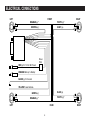
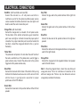
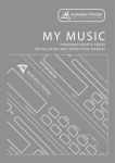
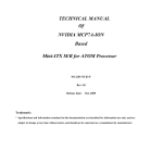
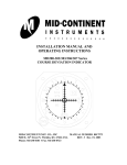
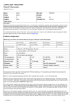
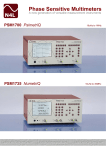
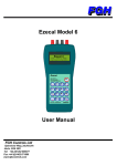
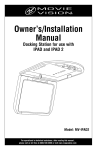
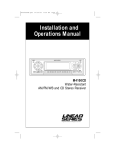
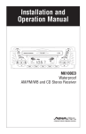
Owner's Manual
VOLUME
ON/OFF
FADER
TONE
ME
ST
FM
1
2
3
4
5
6
M
TIME
H
CH
LOC
RCL
TUNING
PUSH
FM/
AM
LO/
DX
SEEK
SCAN
BALANCE
AM/FM Stereo Receiver with Digital Clock,
Seek / Scan / Manual Tuning
Model PPC-200
CONTROLS AND OPERATIONS
12
VOLUME
8 10
5
FADER
TONE
ON/OFF
ME
ST
FM
1
2
3
4
5
6
TIME
M
CH
LOC
RCL
PUSH
TUNING
FM/
AM
7
9
LO/
DX
SEEK
SCAN
BALANCE
1
2
11
On / Off / Volume / Balance / Control Knob (1)
To turn the unit on, rotate the the volume control knob to the
right. To adjust the the volume level, continue rotating the knob
to the right. To turn the unit off, rotate the knob to the left until it
clicks. Push in on the volume knob and rotate the knob from left
to right to change the relative output of the left and right
speakers. Adjust the balance control to your listing preference.
6
3
4
Fader Control Knob (3)
Rotating the fader control knob from left to right will change the
relative output level of the front or rear speakers. Adjust the
fader control to your listening preference.
Time Set Control Knob (4)
The time set control knob is used in conjunction with the
memory button (ME) to set the clock. Please refer to the “how to
set the clock” section of this manual for further details.
Tone Control Knob (2)
Rotating the tone control knob from right to left will adjust the
overall tone quality higher or lower. Make the tone adjustment to
your desired preference.
Station Recall Buttons (5)
The station recall buttons are used in conjunction with the
memory (ME) button to memorize desired radio stations and
recall them. (See the “How to Preset Radio Stations” section of
this manual for further details)
2
CONTROLS AND OPERATIONS
Seek/ Scan Button (6)
Pressing the seek button will cause the tuner to search out the
next strongest station up the tuning scale. To continue seeking,
you must repeatedly press the seek button each time the tuner
stops on a station.
Pressing the scan button will put the tuner into scan mode. When
in the scan mode, the tuner will seek up to the next strongest
radio station and stop for eight seconds. After 8 seconds the
tuner will again seek up to the next strongest stations and hold
for 8 seconds. To stop the scan mode, simply press the scan
button once again and the tuner will stop scanning.
Local Distant Button (11)
Switch the LO/DX button to the LO position to prevent strong
local stations from overlapping weaker stations. For normal
operation and maximum sensitivity, switch to the DX position.
Note: When in the LO mode, “LOC” will be displayed in the
display area.
Multi-Function LCD Area (12)
The LCD display area will indicate the following operating
functions:
* Radio frequency and clock time.
* FM1, FM2 and AM1 radio bands.
* Local radio reception mode and last preset memory button
pushed.
Manual Up / Down Tuning (7)
To manually tune a station up or down the scale, simply press
the the up or down side of the manual tuning button. Hold the
button down until you get close to the station and release it.
Fine tune by pressing the button repeatedly.
Display Priority
The priority of the PPC-200 display area is dedicated to the
radio frequency. If the recall button is pushed to see the time,
the display will always change back to the clock after 5 seconds.
Memory Button (8)
The memory button is used with the station recall buttons and
the clock set button to program radio stations and set the clock.
(See “how to set the clock and how to preset radio stations” for
more details)
How to Set the Time
Repeat the following procedures to properly set the clock time.
1. Turn on the unit by rotating the volume control knob to the
right.
2. Press the recall button to turn the display from the radio
frequency to the clock mode.
3. Press and release the memory button while the clock time is
displayed in the LCD area, the time showing will begin to
flash.
4. While the display is flashing, rotate the time set control knob to
the left to adjust the time and to the right to adjust the minutes.
5. Once the correct time is showing in the display, let the display
change back to the radio station before turning the unit off.
FM/AM Select Button (9)
Repeated pressing of the FM/AM button will change the tuner
from FM1 band to FM2 band and to AM operation. The particular
band will be displayed in the display area. Select the band you
wish to listen to by repeated pressing of the FM/AM button.
Recall Button (10)
Pressing the recall button will change the display from the radio
frequency to the clock. If you want to see the time in the display,
simply press the recall button and the clock will appear for 5
seconds.
3
CONTROLS AND OPERATIONS
How to Preset Radio Stations:
Repeat the following procedures to memorize radio stations:
1. Turn on the unit by rotating the volume control knob to the
right.
2. Select the radio band (FM1, FM2, AM1) you want to memorize
radio stations in by pressing the FM/AM button.
3. Use the manual tuning button to select a radio station you
want to set into memory.
4. Press the memory button (ME) and release it. A "CH" indicator
will begin to flash in the display area.
5. Press the station recall button you want that station memorized
on (1-6).
6. Select the next band (FM1, FM2, AM1) and repeat steps 3,4
and 5 to memorize radio stations on all bands.
4
INSTALLING THE RADIO
1
2
5
4
3
5
2
6
2
1. Anchoring Board
2. Flat Washer
3. Machine Screw
4. Mounting Strap
5. Hex Nut
6. Shaft Nut
7. Dashboard
8. Trim Plate
2
7
8
6
Installing the Radio
1. Locate the factory supplied opening for the radio or choose a location within reach of
the primary operator of the vehicle.
2. Cut and file the opening if necessary so the shafts and the nosepiece of the radio will
slide through the opening.
3. Place the spacing nuts and washers on the shafts and adjust them so that the nosepiece
and shafts stick through the mounting far enough for the face plate to be positioned and
held into place using the remaining nuts and washers. If the face plate is not used,
adjust the radio depth so that the knobs will fit and operate smooth and correctly.
5
4. Support the rear of the chassis using the
perforated back strap and nuts supplied.
Attach the back strap to the rear chassis of
the radio and find a secure, solid location
to attach the end of the back strap.
Note: Reluctance to use or properly
install the back strap will result in
damage to the shafts and will cause the
nosepiece to become distorted.
ELECTRICAL CONNECTIONS
FRONT
LEFT
RIGHT
WHITE (-)*
ORANGE (-)*
GRAY (+)
BROWN (+)
Noise
Filter
RED (+) To 12 Volt DC Power
ORANGE Memory to Battery
BLACK (-) To Ground
YELLOW Power Antenna
BLUE (+)
GREEN (+)
WHITE (-)*
ORANGE (-)*
REAR
LEFT
6
RIGHT
ELECTRICAL CONNECTIONS
Red Wire: (with fuse holder and noise filter)
Connect the red wire to a +12 volt power source that is
“switched on and off by the ignition key. Most power sources
can be located at the vehicles fuse block. Use a test light or volt
meter to select the correct connection point.
Gray Wire:
Connect the gray wire to the positive terminal of the right front
speaker.
Green Wire:
Connect the green wire to the positive terminal of the left rear
speaker.
Orange Wire: (with fuse holder)
Connect the orange wire to a constant +12 volt power source.
The fuse block of the vehicle will provide a good connection
point. Use a test light or volt meter to locate the proper point of
connection. If a proper connection point can not be found at the
fuse block, connect the orange wire directly to the (+) post on
the battery.
Blue Wire:
Connect the blue wire to the positive terminal of the right rear
speaker.
White Wire:
Connect the white wire to the negative terminals of all speakers
used for the right channel.
Yellow Wire:
The yellow wire will provide +12 volts when the on/off control of
the radio is switched to on. The yellow wire is used to trigger a
power antenna relay. Connect the yellow wire to the positive
trigger wire of the power antenna relay.
Orange Wire:
Connect the orange wire to the negative terminal of all speaker
used for the left channel.
Black Wire:
Connect the black wire to the frame of the vehicle. Crimp a ring
terminal to the black wire and use a nut a bolt to secure it to the
vehicle chassis. A good ground is essential for proper
performance of the PPC-200 unit.
Note: In the wiring diagram there is more than one white and
orange wire show. This is for clarification of connection of the
white and orange wire. There is only one white wire and one
orange wire provided on the harness.
Brown Wire:
Connect the brown wire to the positive terminal of the left front
speaker.
7
SPECIFICATIONS
WARRANTY
ONE (1) YEAR LIMITED WARRANTY
FM Tuner
Range . . . . . . . . . . . . . . . . . . . . . . . . . . . . . . . . . 87.5 - 107.9MHz
Usable Sensitivity . . . . . . . . . . . . . . . . . . . . . . . . . . . 17dBf (2uV)
50dB Quieting Sensitivity . . . . . . . . . . . . . . . . . . 23.2dBf (4uV)
Signal to Noise Ratio . . . . . . . . . . . . . . . . . . . . . . . . . . 60dB
Stereo Separation (@ 1kHz) . . . . . . . . . . . . . . . . . . . . . . . 35dB
Capture Ratio . . . . . . . . . . . . . . . . . . . . . . . . . . . . . 2.5dB
Alternate Channel Selectivity . . . . . . . . . . . . . . . . . . . . . . 65dB
Magnadyne Corporation or its authorized agents will within 1 year from the date of
sale to you, repair, replace or refund the retail sales price of said product or any part
thereof, at the option of the Magnadyne Corporation or its authorized agents, if said
product or part is found defective in materials or workmanship, when properly
connected and operating on the correct power requirements designated for the
specific product. This warranty and Magnadyne Corporation or its authorized agents
obligations hereunder do not apply where the product was; damaged while in the
possession of the consumer, subjected to unreasonable or unintended use, not
reasonably maintained, utilized in commercial or industrial operations, or serviced by
anyone other than Magnadyne Corporation or its authorized agents, or where the
warning seal on the product is broken or the power and/or plugs are detached from
the unit. Magnadyne Corporation or any of its authorized agents will not assume any
labor costs for the removal and re-installation of any product found to be defective,
or the cost of transportation to Magnadyne Corporation or its authorized agents.
Such costs are the sole responsibility of the purchaser.
This warranty does not cover the cabinet appearance items or accessories used in
connection with this product, or any damaged to recording or recording tape, or any
damage to the to the products resulting from improper installation, alteration,
accident, misuse, abuse or acts of nature.
MAGNADYNE CORPORATION OR ITS AUTHORIZED AGENTS SHALL NOT BE
LIABLE TO ANYONE FOR CONSEQUENTIAL OR INCIDENTAL DAMAGES OR
CLAIMS EXCEPT THOSE ACCORDED BY LAW. NO EXPRESSED WARRANTY
OR IMPLIED WARRANTY IS GIVEN EXCEPT THOSE SET FORTH HEREIN. NO
IMPLIED WARRANTY SHALL EXTEND BEYOND 1 YEAR FROM THE DATE OF
SALE.
This warranty extends only to the original purchaser of the product and is not
transferable.
Some states do not allow limitations on how long an implied warranty lasts, and
some states do not allow the exclusion or limitation of incidental or consequential
damages, so the above limitations or exclusion may not apply to you. This warranty
gives you specific legal rights, and you may have other rights that vary from state to
state.
Defective merchandise should be returned to the original point of purchase or
secondly, to Magnadyne Corporation, 1111 W. Victoria Street, Compton CA 90220,
or 2061 Cohen Street, Montreal, Quebec H4R 2N7. Return Authorization must be
obtained before sending, or merchandise may be refused.
AM Tuner
Range . . . . . . . . . . . . . . . . . . . . . . . . . . . . . . . . . 530-1620kHz
Sensitivity (20dB Quieting) . . . . . . . . . . . . . . . . . . . . . . . . 10uV
Signal to Noise Ratio (@50uV) . . . . . . . . . . . . . . . . . . . . 42dB
Audio Section
Maximum Power Output . . . . . . . . . . . . . . . . . . . . . . 2 x 9 Watts
Continuous Average Power Output (rms) 10% THD . .2 x 5.5 Watts
Power Supply Voltage (Negative Ground) . . . . . . . 14.4 Volts DC
Dimensions
Chassis . . . . . . . . . . . . . . . 178mm (W) x 44mm (H) x 130mm (D)
Nose Piece . . . . . . . . . . . . 105mm (W) x 42mm (H) x 130mm (D)
Weight . . . . . . . . . . . . . . . . . . . . . . . . . . . . . . . . . . . . 1.2kg
© Copyright 1998 Magnadyne Corp.
8