1
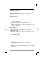
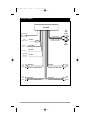
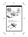
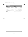
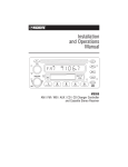
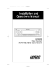
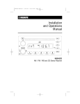
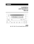
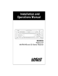
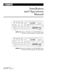
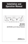
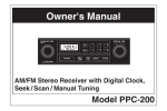
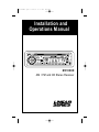
M3100CDUM .qxd
07/24/03
4:17 PM
Page 1
Installation and
Operations Manual
M3100CD
AM / FM and CD Stereo Receiver
®
A Registered Trademark of Magnadyne Corporation
M3100CDUM .qxd
07/24/03
4:17 PM
Page 2
Introduction
Your new M3100CD in-dash entertainment system has been designed to give you many years of listening
pleasure. Take a moment to read through this manual and become familiar with the operations and features
of this outstanding product.
It is advisable to keep this manual in your vehicle so it is readily available for reference. Be sure to fill out
and send in your warranty card to ensure that you receive the full benefits of warranty repair in the unlikely
event that your system will need service. We are confident that you will thoroughly enjoy your new mobile
entertainment system.
Location and Function of Controls at a Glance
1 2
24 23 22 21
3
4
5
6
20
7
8
9
1
3
16
11
24
PWR
VOL
•
3
TUN/TRK •
VOL
6
5
10
2
17
BAND
RPT
RPT A-B
1
2
3
INT
PGM
MEM/CLR
4
5
6
BASS
12
MUTE
22
RDM
7
INFRARED REMOTE CONTROLLER
8
2
9
17
19
10
12
13
18
14
16 15
M3100CDUM .qxd
07/24/03
4:17 PM
Page 3
Location and Function of Controls at a Glance
1. Power On/Off: Turns the unit On/Off.
2. Audio Control Buttons: Adjusts the Volume, Bass, Treble, Balance and Fader.
3. Multi-Function Buttons: Adjusts the radio frequency, sets the clock, and changes CD tracks.
4. Reset Button: Resets the Display Area.
5. Multi-Function Button 1 - RPT:
Radio: Recalls memorized radio station. Programs a radio station into memory (See Radio Operation
for more information).
CD: Continuously repeats the same track. (See CD Operation for more information).
6. Multi-Function Button 2 - RPT A-B:
Radio: Recalls a memorized radio station, and programs a radio station into memory (See Radio
Operation for more information).
CD: Continuously repeats a selection of music. (See CD Operation for more information).
7. Multi-Function Button 3 - RDM:
Radio: Recalls a memorized radio station, and programs a radio station into memory (See Radio
Operation for more information).
CD: Plays all tracks on the current disc in random order. (See CD Operation for more information).
8. Multi-Function Button 4 - INT:
Radio: Recalls a memorized radio station, and programs a radio station into memory (See Radio
Operation for more information).
CD: Plays the first ten seconds of each track. (See CD Operation for more information).
9. Multi-Function Button 5 - PGM:
Radio: Recalls a memorized radio station, and programs a radio station into memory (See Radio
Operation for more information).
CD: Enters CD track program mode (See CD Operation for more information).
10. Multi-Function Button 6 - MEM/CLR:
Radio: Recalls a memorized radio station, and programs a radio station into memory (See Radio
Operation for more information).
CD: Programs a CD track into memory (See CD Operation for more information).
11. AS/PS - ELAPSE Button:
Radio: Automatic memory storing and preset scan (See Radio Operation for more information).
CD: Displays elapsed time of current CD track.
12. Bass Boost Button: Increases Bass output.
13. Radio Station Scan Button: Scans through strong stations in the current radio band.
14. Display Button: Display Priority can be set to either clock or radio frequency.
15. Auxiliary Input Jack: Allows you to listen to an auxiliary input audio source, such as portable MP3 player or cassette player.
3
M3100CDUM .qxd
07/24/03
4:17 PM
Page 4
Location and Function of Controls at a Glance
16. Band Button:
Radio: Selects the desired radio band in the following order: FM1, FM2, FM3, AM1, AM2.
CD: Changes from CD Mode to Radio Mode.
17. Play/Pause Button:
Radio: Changes from Radio Mode to CD Mode.
CD: Pauses disc play.
18. Eject Button: Ejects the disc from the CD Slot.
19. CD Slot: Insert a CD into slot with label facing up.
20. Display Area: Displays radio, clock and CD functions.
21. Infrared Sensor : Receives the signals from the Remote Control allowing you to adjust the basic functions of this unit.
22. Mute Button: Mutes audio level.
23. Auxiliary Button: Accesses Auxiliary Input Mode.
24. Audio Mode Selection Button: Selects the desired audio mode: Volume, Bass, Treble, Balance and Fader.
Audio Beep: Press the SEL button (24) for more then 2 seconds to turn beep on/off.
4
M3100CDUM .qxd
07/24/03
4:17 PM
Page 5
Radio Operation
Select a Band
In Tuner Mode, press the "BAND" button (16) to
select the desired band in the following order:
FM1, FM2, FM3, AM1, AM2. Each band can store
up to six preset stations.
Band Button
Press the "BAND" button (16) while in Radio
Mode to change to CD Mode.
Tuning
Manual Tuning: Press and hold the
or
button (3) for more than 4 seconds then release.
Then press and release the
or
button until
desired frequency is selected. The unit will default
back to Seek Tuning Mode after 5 seconds of no
button activity.
Seek Tuning: Press the
or
button to move
to the next station automatically.
Automatically Store Stations
Select six strong stations and store them in the
current band:
Select a Band (if needed). Press and hold the
button (11) for more than three seconds.
The new stations replace stations already stored
in that band.
Preset Scan
Scan stations stored in the current band:
Select a Band (if needed). Press the
button
momentarily. The radio pauses for ten seconds at
each preset station. When desired station is
reached, press the
button again to stop
scanning.
Preset Stations
Six numbered preset buttons store and recall stations for each band.
Select a Band (if needed). Select a station by
pressing the
or
button. Press and hold
any of the preset buttons for three seconds to
memorize the station. The preset number will
appear in the display.
Recall a Station
Select a Band (if needed). Press one of the six
preset buttons to select a stored station.
Scan
Press the
button (13) to scan through strong
stations in the current band. The radio will pause
for five seconds at each strong station. To listen
to the current station, press the
button again.
Sound Controls
Audio Mode Selection Button
Selects the desired audio mode by pressing the
button (24). The modes will be displayed the
following order: Volume, Bass, Treble, Balance
and Fader.
Volume
Adjust the volume by pressing the
O = Minimum Volume
46 = Maximum Volume
or
button.
Initial Volume Level
To program the Initial Volume Level, adjust the
volume to the desired level, then press and hold
the
PWR button for more than 3 seconds. The
next time the unit is turned on, the volume will be
at this initial level.
Bass
Press SEL button two times. Adjust the Bass up
or down by pressing the
or
button.
-6 = Minimum Bass
+6 = Maximum Bass
Treble
Press SEL button three times. Adjust the Treble
up or down by pressing the
or
button.
-6 = Minimum Treble
+6 = Maximum Treble
Balance
Press SEL button four times. Adjust the Balance
left or right by pressing the
or
button.
R12 = Right speakers only
C0 = Equal sound right and left
L12 = Left speakers only
Fader
Press SEL button five times. Adjust the Fader
front or rear by pressing the
or
button.
R12 = Front speakers only
C0 = Equal sound front and rear
L12 = Rear speakers only
5
M3100CDUM .qxd
07/24/03
4:17 PM
Page 6
General Operations
Power
Press the
PWR button to turn the unit On/Off.
Audio Beep
Press and hold the "SEL" button (24) for 3 seconds to turn beep On/Off. A
icon will appear
in the display.
Mute
Press the "MUTE" button (22) to mute audio level.
Press again to release this function.
Reset Display
Activate the Reset button (4) with either a ballpoint pen tip or paper clip for the following reasons:
• After initial installation of the unit is completed.
• When the function buttons do not operate.
• Error symbol on the display.
If there is a disc in the slot when the reset button
is pressed the disc will be ejected.
Bass Boost
Press the
button (12) to increase bass output. "BASS" will appear in the display.
Display Priority
Clock Display Priority: Press and hold the
button (14) while pressing the
button (3) to
select Clock Priority. Pressing the
button
while in Clock Priority will temporarily display
selected station frequency.
In CD Mode: When the display priority is set to
"Clock", the clock will be displayed indicating
the current time. Pressing the
button
will temporarily display CD track number, time
remaining or elapsed time depending on current CD display option selected. After 5 seconds the display will return to the clock.
Frequency Display Priority: Press and hold button (14) while pressing the
button (3) to
select Frequency Priority. Pressing
button
while in Frequency Priority will temporarily display the clock.
In CD Mode: When the display priority is set to
"Frequency", the CD track number will be displayed. Pressing the
button will temporarily display the clock. After 5 seconds the
display will return to the CD display.
6
Setting the Clock
In Clock Priority, press and hold the
button
(14) for 3 seconds until the colon flashes, then
release. Then press the
button to adjust the
hours, or press the
button to adjust the minutes.
Auxiliary Input Mode
Press the AUX button (23) to access Auxiliary
Input Mode (Only available if an auxiliary audio
device is plugged into the Auxiliary Input Jack).
Auxiliary Input Jack (15)
Plug an audio device into this jack (15). Allows
you to listen to an auxiliary audio source (MP3
player, portable cassette player, etc.). Connection
cable not supplied with this unit.
M3100CDUM .qxd
07/24/03
4:17 PM
Page 7
CD Player Operation
Inserting and Ejecting a CD
Push a CD into the CD Slot, label side up, and the
CD will begin to play.
Press the
EJECT button (18) to stop CD play
and eject the CD from the slot.
Select Tracks
Press the
or
button (3) for less than a
second to move to the previous or next track. The
track number appears in the Display Area.
Fast Forward and Fast Reverse
Press the
or
button (3) for more than one
second to fast forward or fast reverse. CD play
starts from when you release the button.
Pause Disc Play
Press the
button (17) to pause CD play.
Press it again to resume play.
Band Button
Press the "BAND" button (16) while in CD Mode
to change to Radio Mode.
Repeat the Same Track
Press the
button (5) to continuously repeat
the same track. Press it again to stop Repeat.
Program CD Tracks
Use the Program function to select up to 8 CD
tracks to play in any order. Program allows you to
select a track number for each spot in the playing
sequence. A CD must be inserted to use the
Program function.
1. Press the
or
button (3) to choose a track
number.
2. Press the
button (10) to enter track number into memory. Display shows next track number in sequence. continue (up to 8 times) for all
desired tracks.
3. Press the
button (9) to play CD in programmed order.
Repeat Selection (RPT A-B)
The Repeat Selection function allows you to
select a portion of a music track and play it back
continuously.
1. While the music track is playing, press the
button (6) to set the beginning point.
2. Allow the music to play along as far as desired,
then press
again to set the end point. The
selection of music will then continuously play.
3. To stop the Repeat Selection, press the
button to clear the selection.
Play All Tracks in Random Order
Press the
button (7) to play all tracks on
the current CD in random order. Press it again to
stop Random.
Track/Time Display
To change display from track number to elapsed
time, press the
button (11).
Intro Scan
Press the
button (8) to play the first ten
seconds of each track. Press it again to stop Intro
Scan and listen to the track.
Notes on CD-Rs and CD-RWs:
• The unit cannot play a CD-R and CD-RW that is
not finalized. (Please refer to the manual of your
CD-R/CD-RW recorder or CD-R/CD-RW software
for more information on the finalizing process).
• This unit will not play MP3 music or WMA music
recorded on any CD-R or CD-RW disc.
• Be sure to only use discs with the following labels
in this unit:
7
M3100CDUM .qxd
07/24/03
4:17 PM
Page 8
Installation Procedure
Step 1: The radio chassis is designed to be “Sleeve
Mounted” through a opening in the dashboard panel.
The required opening size is 182mm (7-3/16") x
84mm (3-5/16"). Cut or enlarged an opening in the
dashboard to accommodate the mounting sleeve.
Step 2: If you are replacing an existing factory
installed radio, an adapter harness might be available for your vehicle to eliminate the need for cutting your factory wiring. Contact Radio Shack or
other car stereo installation centers for the availability of a harness for your vehicle.
Step 3: Insert the mounting sleeve into the hole in
the dashboard. Bend the metal tabs on the sleeve to
secure the mounting sleeve to the dashboard.
Step 4: Bring all wiring for the connection of the unit
(including the antenna) through the center of the
mounting sleeve. Connect the wiring as follows:
Yellow Wire (w/Fuse): Connect this wire to a constant +12 volt power source (a power source that is
not controlled by the ignition key).
Red Wire: Connect this wire to a switched +12 volt
power source (a power source turned on and off by
the ignition key).
Gray Wire with Black Stripe: Connect this wire to the
Right Front Speaker (-) negative terminal or wire.
Purple Wire with Black Stripe: Connect this wire to the
Right Rear Speaker (-) negative terminal or wire.
Purple Wire: Connect this wire to the Right Rear
Speaker (+) positive terminal or wire.
Gray Cable with Red/White RCA Connectors:
Provides L/R Channel audio signal output to an
additional amplifier.
Note: This unit is designed to connect to (4) four
speakers. If the installation only requires (2) two
speakers, use the White and Gray wire sets to connect the speakers.
Remove Transportation Screws: Before installing
the unit, please remove the two screws shown in the
illustration below.
Remove Transportation
Screws Before
Installation
Blue Wire: Connect this wire to the (+) power
antenna activation circuit. If no power antenna
exists, tape-off the end of this wire to prevent shorting out the unit.
Black Wire: Connect this wire to the frame of the
vehicle (ground). This wire is the chassis grounding
wire for the unit.
White Wire: Connect this wire to the Left Front
Speaker (+) positive terminal or wire.
White Wire with Black Stripe: Connect this wire to the
Left Front Speaker (-) negative terminal or wire.
Green Wire with Black Stripe: Connect this wire to the
Left Rear Speaker (-) negative terminal or wire.
Green Wire: Connect this wire to the Left Rear
Speaker (+) positive terminal or wire.
Gray Wire: Connect this wire to the Right Front
Speaker (+) positive terminal or wire.
8
WARNING!
Any wires left unconnected must be taped-off
or capped off to prevent shorting.
DO NOT connect speaker ground wires together.
DO NOT connect speaker ground wires to the
chassis of the vehicle.
DO NOT connect front and rear speaker wires
together.
FAILURE TO FOLLOW ANY OF THESE WARNINGS WILL RESULT IN DAMAGE TO THIS
UNIT AND VOIDS THE WARRANTY.
M3100CDUM .qxd
07/24/03
4:17 PM
Page 9
Wiring Diagram
M3100CD
Red
Right
Channel
Antenna Socket
Audio Line Out
Ignition
Red Wire
Switch (+12v in )
Battery
(+12v in)
Ground (B-)
Connect to Line Input
of Optional Amplifier
Yellow Wire
White
Left
Channel
Black Wire
Power Antenna
Blue Wire
(Switched
+12v out)
Left
Front
Speaker
White Wire
Gray Wire
White Wire with Black Stripe
Gray Wire with Black Stripe
Left
Rear
Speaker
Green Wire
Violet Wire
Green Wire with Black Stripe
Violet Wire with Black Stripe
Right
Front
Speaker
Right
Rear
Speaker
9
M3100CDUM .qxd
07/24/03
4:17 PM
Page 10
Final Installation
Sheet Metal
Screw
Nut
Washer
Metal Strap
Push Out Mounting
Sleeve Tabs
Dashboard
Mounting Sleeve
Release Lever
Removing the Unit from Dashboard:
Remove the metal strap holding the back of the radio chassis.
Insert the removal keys into the small slots on the left and right side of chassis panel.
Push the removal keys until they engage the release levers.
Pull the unit out.
Removal Keys
10
M3100CDUM .qxd
07/24/03
4:17 PM
Page 11
Specifications
CD Player
Signal/Noise Ratio . . . . . . . . . . . . . . . . > 86 dB
Frequency Response . . . . . . . . 20 Hz – 20 kHz
Channel Separation . . . . . . . . . . . . . . . > 65 dB
D/A Converter . . . . . . . . . . . . . . . . . . . 1 Bit/CH
FM Tuner
Tuner Range . . . . . . . . . . . . 87.5 – 107.9 MHz
FM Mono Sensitivity . . . . . . . . . . . . . . . 12 dBf
50 dB Quieting Sensitivity (Stereo) . . . . 16 dBf
Stereo Separation @ 1 kHz . . . . . . . . . . 40 dB
Amplifier
Total System Power . . . . . . . . 180 Watts Peak
Power Output . . . . . . . . . . . . . . . . . . . 4 x 45W
General
Power Supply . . 11-16 VDC, Negative Ground
Speaker Output Impedance . . . . . . 4 – 8 Ohms
Fuse . . . . . . . . . . . . . . . 10 Amp Fast Blow ATO
Dimensions . . . . . . . . . . . . . . . . . . .7" x 7" x 2"
. . . .178 mm (W) x 178 mm (D) x 55 mm (H)
Specifications are subject to change without notice.
AM Tuner
Tuner Range . . . . . . . . . . . . . . 530 – 1720 kHz
11
M3100CDUM .qxd
07/24/03
4:17 PM
Page 12
Warranty
ONE (1) YEAR LIMITED WARRANTY
Magnadyne Corporation or its authorized agents will within one year from the date of sale to
you, repair, replace or refund the retail sales price of said product or any part thereof, at the
option of the Magnadyne Corporation or its authorized agents, if said product or part is found
defective in materials or workmanship, when properly connected and operating on the correct power requirements designated for the specific product. This warranty and Magnadyne
Corporation or its authorized agents obligations hereunder do not apply where the product
was; damaged while in the possession of the consumer, subjected to unreasonable or unintended use, not reasonably maintained, utilized in commercial or industrial operations, or
serviced by anyone other than Magnadyne Corporation or its authorized agents, or where the
warning seal on the product is broken or the power and/or plugs are detached from the unit.
Magnadyne Corporation or any of its authorized agents will not assume any labor costs for
the removal and reinstallation of any product found to be defective, or the cost of transportation to Magnadyne Corporation or its authorized agents. Such cost are the sole responsibility of the purchaser.
This warranty does not cover the cabinet appearance items or accessories used in connection with this product, or any damage to recording or recording tape, or any damage to the
products resulting from improper installation, alteration, accident, misuse, abuse or acts of
nature.
MAGNADYNE CORPORATION OR ITS AUTHORIZED AGENTS SHALL NOT BE LIABLE TO
ANYONE FOR CONSEQUENTIAL OR INCIDENTAL DAMAGES OR CLAIMS EXCEPT THOSE
ACCORDED BY LAW. NO EXPRESSED WARRANTY OR IMPLIED WARRANTY IS GIVEN
EXCEPT THOSE SET FORTH HEREIN. NO IMPLIED WARRANTY SHALL EXTEND BEYOND
ONE YEAR FROM THE DATE OF SALE.
This warranty extends only to the original purchaser of the product and is not
transferable. Some states do not allow limitations on how long an implied warranty lasts, and
some states do not allow the exclusion or limitation of incidental or consequential damages,
so the above limitations or exclusion may not apply to you. This warranty gives you specific
legal rights, and you may have other rights that vary from state to state.
Defective merchandise should be returned to the original point of purchase or
secondly, to:
Magnadyne Corporation
1111 W. Victoria Street
Compton CA 90220
www.magnadyne.com
Return Authorization must be obtained before sending, or merchandise may be refused.
© Copyright 2003
Magnadyne Corporation
M3100CDUM Rev. A 6-10-03