1
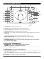
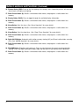
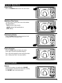
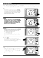
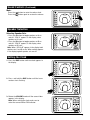
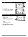
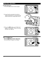
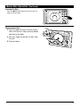
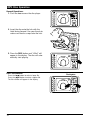
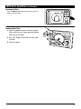
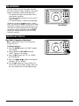
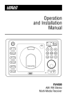
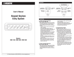
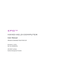
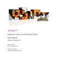
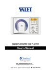
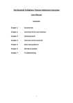
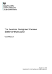
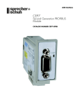
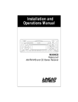
® Operation and Installation Manual FM SPK PUSH EQ 1 AS/PS 2 SLP 3 ALM 4 DISP 5 DIM 6 ST SPEAKER A B AUX AM/FM DISC 3-Beam Laser Pickup RESET AUX HEADPHONES ® RV4000 AM / FM Stereo Multi-Media Receiver Introduction Please take the time to read all of the information in this manual. Familiarity with operation and installation procedures will help you obtain the best possible performance from your new AM/FM Stereo Multi-Media Receiver. WARNING! To prevent fire or electrical shock hazard, do not expose this product to moisture, or remove cover or bottom screws. No user-serviceable parts inside. Refer servicing to qualified personnel. Index Button Locations and Functions 3-4 General Operation 5 Sound Controls 5-7 Speaker Selection 7 Setting the Clock 7-8 Sleep Timer Operation 8 Alarm Operation 9 Radio Operations 10-11 Disc Warnings 11 Music Disc Operation 12-13 MP3 Disc Operation 14-15 Audio Input 16 Headphone Output 16 Reset Button 17 Additional Feature 17 Installation18 Speaker Connections 19 Wiring and Auxiliary Connections 20 Safety Instructions 21 Warranty22 2 Button Locations and Functions 2 1 3 4 5 FM SPK PUSH 27 26 EQ 1 ST SPEAKER A B AUX AM/FM 7 25 24 AS/PS 2 DISC 23 22 SLP 3 ALM 4 DISP 5 DIM 6 11 21 20 19 18 9 6 8 10 12 3-Beam Laser Pickup 17 16 RESET AUX HEADPHONES 13 ® 15 14 1. Power On/Off: Press to turn the unit on or off. 2. Disc Door: To play a disc, insert the disc with label facing forward. 3. Disc Door Release: Press to open the door so the disc can be inserted. 4.Auxiliary Button (AUX): Press to choose auxiliary audio in mode. 5.Display Area: This area displays all function information for the radio, clock, disc player and auxiliary input device. 6. Mute Button: Press to mute the audio, press again to restore the audio. 7. Speaker Selection Buttons: Press to switch the speakers sets A and B on and off. 8.Disc Button: Press to select the music player mode. 9.Radio Button (AM/FM): Press to select the radio mode. Sequential presses will select radio band: FM 1, FM 2, FM 3, AM 1 and AM 2. 10. Play/Pause Button (�ll): Press to pause disc play, press again to resume play. 11. Seek Down (l��), Seek Up (��l) Buttons: Radio Mode: Press to tune the radio to a lower or higher radio station. Disc Mode: Press to search for the beginning or next track. 12. Volume and Select Button: Rotate to increase or decrease the volume level. Press to select the sound controls: Bass, Treble and Balance. 13. Headphone Socket: Accepts 3.5mm stereo headphone jacks. 14. Audio Input Jack: Press the AUX button until “Audio” appears in the display then plug in a device via the 3.5mm audio input socket. Note: The RV4000 does not control the device, it just allows the audio to be played through the system. 15. Reset Button: Press to reset the unit to it’s default settings. 3 Button Locations and Functions (Continued) 16. Dimmer Button (DIM): Press to dim the lighting in the display area. Sequential presses will select different levels of display area lighting. 17. Radio Preset Button (6): Recalls a memorized radio station, and programs a radio station into memory. 18. Display Button (DISP): Press to toggle through the available display information. 19. Radio Preset Button (5): Recalls a memorized radio station, and programs a radio station into memory. 20. Alarm Button: Sets the alarm. (See “Alarm Operation” for more details). 21. Radio Preset Button (4): Recalls a memorized radio station, and programs a radio station into memory. 22.Sleep Button: Sets the sleep timer. (See “Sleep Timer Operation” for more details). 23. Radio Preset Button (3): Recalls a memorized radio station, and programs a radio station into memory. 24. Radio AS/PS Button: Automatic radio station memory storing (AS) and Preset radio station scanning (PS). (See “AM/FM Operation” for more details). 25. Radio Preset Button (2): Recalls a memorized radio station, and programs a radio station into memory. 26. EQ/LOUD Button (Equalizer and Loudness): Press to select between the preset sound equalization settings. Press and hold the button to boost high and low tones at low volume levels (loudness). 27. Radio Preset Button (1): Recalls a memorized radio station, and programs a radio station into memory. 4 General Operations Power On/Off: PUSH EQ 1 AS/PS 2 SLP 3 ALM 4 DISP 5 DIM 6 To select a play source, press one of the following mode buttons: EQ 1 AUX (Auxiliary Audio Input), AS/PS 2 SLP 3 AM/FM (AM or FM Radio Band) or DISC (Music) Press and hold to perform clock setting functions (See “Setting the Clock” for more details). AUX AM/FM ALM 4 DISP 5 DIM 6 1 2 SLP 3 ALM 4 DISP 5 DIM 6 B AM/FM RESET 1 2 SLP 3 ALM 4 DISP 5 DIM 6 AV DISC HEADPHONES ST FM SPEAKER A B AUX AM/FM RESET AV DISC HEADPHONES ST FM SPK EQ ST A PUSH AS/PS HEADPHONES AUX SPK EQ DISC SPEAKER PUSH AS/PS AV FM SPK Display Selection: Press the DISP button to display the clock. Press again to return to previous display. B PUSH Dimming the Display: Press the DIM button to select the desired level of brightness for the display area. SPEAKER A RESET Selecting a Play Source: ST FM SPK Press the POWER button to turn the unit On/Off. SPEAKER A B AUX AM/FM RESET AV DISC HEADPHONES Sound Controls Volume: Increase the volume by rotating the VOLUME knob clockwise. Decrease the volume by rotating the VOLUME knob counterclockwise. SPK A+B PUSH EQ 1 AS/PS 2 SLP 3 ALM 4 DISP 5 DIM 6 FM SPEAKER A B AUX AM/FM RESET AV DISC HEADPHONES 5 Sound Controls Bass, Treble and Balance Control Select the desired sound mode by pressing the VOLUME knob. The modes will be displayed in the following order: Bass, Treble, Balance and Volume. Bass: Select the Bass mode by pressing the VOLUME knob. Increase the Bass by rotating the VOLUME knob clockwise. Decrease the Bass by rotating the knob counterclockwise. After 6 seconds control reverts back to volume control. PUSH EQ 1 AS/PS 2 SLP 3 ALM 4 DISP 5 DIM 6 EQ 1 AS/PS 2 SLP 3 SPEAKER A B AUX AM/FM RESET AV DISC HEADPHONES Treble: Select the Treble mode by pressing the VOLUME knob. Increase the Treble by rotating the VOLUME knob clockwise. Decrease the Treble by rotating the knob counterclockwise. After 6 seconds control reverts back to volume control. PUSH ALM 4 DISP 5 DIM 6 SPEAKER A B AUX AM/FM RESET AV DISC HEADPHONES Balance: Select the Balance mode by pressing the VOLUME knob. Adjust the Balance by rotating the knob. r -- L = Equal sound right and left r 7 = Right speaker only L 7 = Left speaker only PUSH After 6 seconds control reverts back to volume control. EQ 1 AS/PS 2 SLP 3 ALM 4 DISP 5 DIM 6 EQ 1 AS/PS 2 SLP 3 SPEAKER A B AUX AM/FM RESET AV DISC HEADPHONES Equalizer (EQ): Press the EQ button to choose between the preset equalizer settings: Flat, Classic, Rock, Pop and Jazz as indicated in the display area. PUSH ALM 4 DISP 5 DIM 6 EQ 1 AS/PS 2 SLP 3 SPEAKER A B AUX AM/FM RESET AV DISC HEADPHONES Loud: To boost high and low tones at low volume levels, press and hold the EQ button until “LOUd On” appears in the display. To deselect, press and hold the EQ button again until “LOUd OFF” appears in the display. 6 PUSH Hold ALM 4 DISP 5 DIM 6 SPEAKER A B AUX AM/FM RESET AV DISC HEADPHONES Sound Controls (Continued) Mute: Press the Press the button to mute the volume level. button again to restore the volume. PUSH EQ 1 AS/PS 2 SLP 3 ALM 4 DISP 5 DIM 6 SPEAKER A B AUX AM/FM RESET AV DISC HEADPHONES Speaker Selection Selecting Speaker Sets: • Press the A button to toggle speaker set A on and off. “SPK A” appears in the display when speaker set A is on. • Press the B button to toggle speaker set B on and off. “SPK B” appears in the display when speaker set B is on. Note: When “SPK A+B” appears in the display both speaker sets A and B are on. When nothing appears in the displaying both speaker sets are off. EQ 1 AS/PS 2 SLP 3 ALM 4 DISP 5 DIM 6 ST FM SPK A PUSH SPEAKER A B AUX AM/FM RESET AV DISC HEADPHONES Setting the Clock 1. Press the DISP button until the clock appears in the display. PM PUSH EQ 1 AS/PS 2 SLP 3 ALM 4 DISP 5 DIM 6 SPEAKER A B AUX AM/FM RESET 2. Press and hold the DISP button until the hours number starts flashing. AV DISC HEADPHONES PM PUSH EQ 1 AS/PS 2 SLP 3 SPEAKER A B AUX AM/FM DISC O ALM 4 DISP 5 DIM 6 Hold 3. Rotate the VOLUME knob until the correct Hour appears in the display. Note: When setting the clock make sure to select the correct AM or PM indicator. RESET AV HEADPHONES PM PUSH EQ 1 AS/PS 2 SLP 3 ALM 4 DISP 5 DIM 6 SPEAKER A B AUX AM/FM RESET AV DISC HEADPHONES 7 Setting the Clock (Continued) 4. Press the VOLUME knob and the Minute indicators will start flashing. 5. Rotate the VOLUME knob until the correct Minutes appears in the display. Wait 5 seconds and the colon between the hours and the minutes will start flashing indicating the clock is set. PM PUSH EQ 1 AS/PS 2 SLP 3 ALM 4 DISP 5 DIM 6 SPEAKER A B AUX AM/FM RESET AV DISC HEADPHONES PM PUSH EQ 1 AS/PS 2 SLP 3 ALM 4 DISP 5 DIM 6 SPEAKER A B AUX AM/FM RESET AV DISC HEADPHONES Sleep Timer Operation Setting the Sleep Timer: 1. Press the SLP button until the “SLP 10” appears in the display. 2. Keep pressing the SLP button again until the desired sleep time appears in the display (00, 10, 20, 30, 40, 50, 60, 70, 80 minutes). 3. Wait 5 seconds and the display will return to normal operation and “SLP” will appear in the display. 4. After the designated sleep timer has expired the unit will turn off automatically. Cancelling the Sleep Timer: 1. Press the SLP button until “00” is displayed. 2. Wait 5 seconds and the display will return to normal operation. 8 PUSH EQ 1 AS/PS 2 SLP 3 ALM 4 DISP 5 DIM 6 SPEAKER A B AUX AM/FM RESET AV DISC HEADPHONES Alarm Operation Setting the Alarm Timer: 1. Press the ALM button and the clock will appear in the display with the hour number flashing. 2. Rotate the VOLUME knob until the correct Hour appears in the display. “ALM” will appear in the display indicating the alarm is activated. Note 1: When setting the alarm clock make sure to select the correct AM or PM indicator. Note 2: When setting the alarm DO NOT use 12:00 AM, because that time is used to cancel the alarm. 3. Press the VOLUME knob and the minute indicators will start flashing. 4. Rotate the VOLUME knob until the correct minutes appears in the display. Wait 5 seconds and the colon between the hours and the minutes will start flashing. The letter “ALM” will appear in the display indicating the alarm is set. 5. Press the POWER button to turn the unit off. The unit will automatically turn on when the set alarm time is reached. PM PUSH EQ 1 AS/PS 2 SLP 3 ALM 4 DISP 5 DIM 6 SPEAKER A B AUX AM/FM RESET AV DISC HEADPHONES PM PUSH EQ 1 AS/PS 2 SLP 3 ALM 4 DISP 5 DIM 6 SPEAKER A B AUX AM/FM RESET AV DISC HEADPHONES PM PUSH EQ 1 AS/PS 2 SLP 3 ALM 4 DISP 5 DIM 6 EQ 1 AS/PS 2 SLP 3 SPEAKER A B AUX AM/FM RESET AV DISC HEADPHONES PM PUSH ALM 4 DISP 5 DIM 6 SPEAKER A B AUX AM/FM RESET AV DISC HEADPHONES ALM PUSH EQ 1 AS/PS 2 SLP 3 ALM 4 DISP 5 DIM 6 SPEAKER A B AUX AM/FM RESET AV DISC HEADPHONES Cancelling the Alarm Timer: Follow the procedures above except set the alarm time to 12:00 AM. When the display exits alarm timer programming the “ALM” will disappear from the display indicating the alarm has been cancelled. 9 Radio Operations Selecting the Play Source: ST SPK A Press the AM/FM button and “rAdIO” appears in the display. After a brief moment either AM or FM will appear in the display. PUSH Selecting the AM or FM: Press the AM/FM button repeatedly and select from FM 1, FM 2, FM 3, AM 1 or AM 2. EQ 1 AS/PS 2 SLP 3 ALM 4 DISP 5 DIM 6 A B AUX AM/FM RESET Band Indicator SPK A Preset Band Group SPEAKER FM AV HEADPHONES FM Stereo Indicator ST Radio Frequency Preset Button Number Seek Tuning in a Radio Station: ST SPK A Press and release the l�� button to tune in a lower radio station. Press and release the ��l button to tune in a higher radio station. PUSH EQ 1 AS/PS 2 SLP 3 Note: The unit will automatically switch from FM Mono to FM Stereo when the signal strength increases to a stereo level. If the stereo signal should become weak, the unit will switch back to Mono. FM stereo reception is indicated when “ST” appears in the display. ALM 4 DISP 5 DIM 6 DISC SPEAKER A B AUX AM/FM RESET AV DISC HEADPHONES Manual Tuning in a Radio Station: Press and hold the l�� button to manually tune in a lower radio frequency. Press and hold the ��l button to manually tune in a higher radio frequency. 1 AS/PS 2 SLP 3 ALM 4 DISP 5 DIM 6 SPEAKER A B AUX AM/FM RESET Memorizing Radio Stations: 1. Press the AM/FM button to select either the FM 1, FM 2, FM 3, AM 1 or AM 2 radio band. 2. Tune-in the desired radio station. 3. To memorize the station press and hold anyone of the six radio station recall buttons until the preset number appears. 10 ST SPK A PUSH EQ AV DISC Hold HEADPHONES ST SPK A PUSH EQ 1 AS/PS 2 SLP 3 ALM 4 DISP 5 DIM 6 SPEAKER A B AUX AM/FM RESET AV DISC HEADPHONES Radio Operation (Continued) Automatically Store Radio Stations: 1. Press the AM/FM button to select either the FM or AM radio band. 2. Press and hold the AS/PS button then release. The tuner will search for the strongest stations and store them into memory. The new stations will replace stations that were previously stored in the current band. ST SPK A PUSH Hold EQ 1 AS/PS 2 SLP 3 ALM 4 DISP 5 DIM 6 SPEAKER A B AUX AM/FM RESET AV DISC HEADPHONES Note: When the FM band is selected the 18 strongest stations will be stored. When AM band is selected the 12 strongest stations will be stored. Scanning Stored Radio Stations: 1. Press the AM/FM button to select either the FM or AM radio band. 2. Press the AS/PS button then release. The tuner scans for preset stations stored in the current band and pauses for 6 seconds at each station. When a desired station is reached, press the AS/PS button again to stop scanning. ST SPK A PUSH EQ 1 AS/PS 2 SLP 3 ALM 4 DISP 5 DIM 6 SPEAKER A B AUX AM/FM RESET AV DISC HEADPHONES Disc Warnings DVD and Cleaning: Handling 12cm discscratches and warping disc will cause • Dirt, dust, (Single-sided non operation. disc only) •Do CDnot place stickers on disc or scratch disc. • Do not warp 12cm disc discs. • A disc should always be kept in its case when not in use to prevent damage. MP3 • Do not place discs in the following places: 12cm disc 1. Direct sunlight. 2. Dirty, dusty and damp areas. 3. Near car heaters. 4. Car seats or dashboard. Label side up Do not touch the underside of the disc Do not bend Disc Cleaning: Use a dry soft cloth to wipe disc the surface. If the disc is quite dirty, use a soft cloth slightly moist with isopropyl (rubbing) alcohol. Never use solvents such as benzine, thinner or conventional record cleaners as they may mar the surface of the disc. Wipe the disc from the center toward the outside edge Note: A disc may become somewhat scratched (although not enough to make it unusable) depending on handling and conditions in the usage environment. Rough spots on outside edge 11 Rough spots on Music Disc Operation General Operations: 1. Push the door access the disc player. ST SPK A PUSH EQ 1 AS/PS 2 SLP 3 ALM 4 DISP 5 DIM 6 EQ 1 AS/PS 2 SLP 3 SPEAKER A B AUX AM/FM RESET AV DISC HEADPHONES 2. Insert the disc onto the hub with the label facing forward. Use your thumb to make sure the disc snaps onto the hub. 3. Press the DISC button and “LOAd” will appear in the display. The disc will automatically start playing. PUSH ALM 4 DISP 5 DIM 6 12 B AUX AM/FM RESET AV DISC HEADPHONES Track Number Music Track Selection: Press the l�� button to select a lower track. Press the ��l button to select a higher track. The track number will appear in the display. SPEAKER A PUSH EQ 1 AS/PS 2 SLP 3 ALM 4 DISP 5 DIM 6 SPEAKER A B AUX AM/FM RESET AV DISC HEADPHONES Music Disc Operation (Continued) Pausing the Disc: Press the �ll button to pause the disc, press it again to resume play. PUSH EQ 1 AS/PS 2 SLP 3 ALM 4 DISP 5 DIM 6 SPEAKER A B AUX AM/FM RESET AV DISC HEADPHONES Removing the Disc: 1. Push the door to access the disc player. Wait until the disc stops spinning before opening up the door. 2. Use your finger to remove the disc from the hub. 3. Close the door. 13 MP3 Disc Operation General Operations: 1. Push the door access the disc player. ST SPK A PUSH EQ 1 AS/PS 2 SLP 3 ALM 4 DISP 5 DIM 6 EQ 1 AS/PS 2 SLP 3 SPEAKER A B AUX AM/FM RESET AV DISC HEADPHONES 2. Insert the disc onto the hub with the label facing forward. Use your thumb to make sure the disc snaps onto the hub. 3. Press the DISC button and “LOAd” will appear in the display. The disc will automatically start playing. PUSH ALM 4 DISP 5 DIM 6 Disc File Selection: Press the l�� button to select a lower file. Press the ��l button to select a higher file. The file number will appear in the display. 14 SPEAKER A B AUX AM/FM RESET AV DISC HEADPHONES File Number PUSH EQ 1 AS/PS 2 SLP 3 ALM 4 DISP 5 DIM 6 SPEAKER A B AUX AM/FM RESET AV DISC HEADPHONES MP3 Disc Operation (Continued) Pausing the Disc: Press the �ll button to pause the disc, press it again to resume play. PUSH EQ 1 AS/PS 2 SLP 3 ALM 4 DISP 5 DIM 6 SPEAKER A B AUX AM/FM RESET AV DISC HEADPHONES Removing the Disc: 1. Push the door to access the disc player. Wait until the disc stops spinning before opening up the door. 2. Use your finger to remove the disc from the hub. 3. Close the door. 15 Audio Input Selecting the Audio Input Source: Note 1: The RV4000 does not control the device, it just allows the audio to be played through the system. Note 2: If the rear audio input is being used once you plug a device into the front audio input jack the audio will be diverted to playing the front device. If the front audio jack is being used you will not be able to select the rear audio input. PUSH EQ 1 AS/PS 2 SLP 3 ALM 4 DISP 5 DIM 6 SPEAKER A B AUX AM/FM DISC RESET AUX HEADPHONES Front Audio Input: Insert the 3.5mm jack from the audio device into the AUX input socket on the front of the housing. Press the AUX button until “Audio” appears in the display. Refer to the audio device’s owner’s manual for proper operation. Rear Audio Input: To select the rear input Audio play source, press the AUX button until “Audio” appears in the display. Refer to the audio device’s owners manual for proper operation. Headphone Output Plugging in Headphone: Insert a 3.5mm headphone jack into the Headphone Output socket. Use the volume knob on the headphone to adjust the audio level. Note: To make it so the sound only can be heard through the headphones press speaker buttons A and B until neither “SPK A” or “SPK B” appears in the display. 16 PUSH EQ 1 AS/PS 2 SLP 3 ALM 4 DISP 5 DIM 6 SPEAKER A B AUX AM/FM RESET AV DISC HEADPHONES Reset Button The LCD display may fail to function normally due to the vehicle’s battery condition, and could require resetting the radio microprocessor if: • The vehicle has been “jump started” from a dead battery condition. • The vehicle battery becomes very low and is quick-charged. • The vehicle battery is removed and replaced. PUSH EQ 1 AS/PS 2 SLP 3 ALM 4 DISP 5 DIM 6 Should any of these conditions occur, simply press and release the RESET button on the radio front panel using the tip of a ball point pen. This will reset the radio microprocessor to the original factory settings. After pressing the RESET button you should recheck to see if the radio functions normally. SPEAKER A B AUX AM/FM RESET AV DISC HEADPHONES Reset Button Additional Feature Area Radio Frequency Adjustment: Note: If operating the unit in the USA do not change the area. To Change the Area: 1. Press the AM/FM button and “rAdIO” appears in the display. 2. Press and hold the VOL/TONE knob until “SEtUP” appears in the display. PUSH EQ 1 AS/PS 2 SLP 3 ALM 4 DISP 5 DIM 6 SPEAKER A B AUX AM/FM RESET AV DISC HEADPHONES 3. Press the �ll button and “US” or “OCEAn” will be displayed. 4. Press the l�� or ��l button to change the setting to “US” or “OCEAn”. 5. Press the �ll button to save the setting. The unit will clear all the station settings. After waiting a few seconds the unit exit programming. 17 Installation 9 3/8” Wall Panel 61/4” Chassis Opening Structural Stud Caution: Do not install radio without rear cover installed: No user-serviceable parts inside. Rear cover provides protection against potential fire hazard. Trim Ring 45/8” 9 3/4” 18 Speaker Connections Right Speaker B Left Speaker B _ Gray/Black Wire Gray Wire _ + Right Speaker A Brown Wire Brown/Black Wire White Wire (Common -) _ Left Speaker A + + White/Black Wire (Common -) 19 + _ Wiring and Auxiliary Connections External Automotive Type Antenna (Optional) Red Wire (+) to 12 Volt DC Power Black Wire Ground Audio In Audio Out 10A Fuse Music Disc Player (Optional) In-Dash Unit (Optional) 20 Safety Instructions • Read Instructions: All the safety and operating instructions should be read before the appliance is operated. • Retain Instructions: The safety and operating instructions should be retained for future reference. • Heed Warnings: All warnings on the appliance and in the operating instructions should be adhered to. • Follow Instructions: All operating and use instructions should be followed. • Water and Moisture: The appliance should not be used near water. For example, near a bathtub, washbowl, kitchen sink, laundry tub, in a wet basement, or near a swimming pool, etc. • Wall or Cabinet Mounting: The appliance should be mounted to a wall or cabinet only recommended by the manufacturer. • Heat: The appliance should be situated away from heat sources such as radiators, heat registers, stoves, or other appliances (including amplifiers) that produce heat. • Power Supply: The appliance should be connected to a power supply only of the type described in the operating instructions or as marked on the appliance. • Power Lines: An outdoor antenna should be located away from power lines. • Object and Liquid Entry: Care should be taken so that objects do not fall, and liquids are not spilled into the enclosure through openings. Outdoor Antenna Grounding: If an outside antenna is connected to the receiver, be sure the antenna system is grounded, so as to provide some protection against voltage surges and built up static charges. Section 810 of the National Electrical Code, ANSI/NFPSNo. 70-1983, provides information with respect to proper grounding of the mast and supporting structure, grounding of the lead-in wire to an antenna discharge unit, size of grounding conductors, location of antenna-discharge unit, connection to grounding electrodes, and requirements for the grounding electrode. See illustration below. Antenna Lead-In Wire (B) Mast Ground Wire (A,B ) 2.44 Meters Ground Clamp Example of Antenna Grounding as per National Electrical Code. Instructions Contained in Article 810-"Radio and Television Equipment" Antenna Discharge Unit (C) Grounding Clamps To Receiver Grounding Electrode Driven 8’ Into the Earth A. Use No. 10 AWG (5.3mm2) copper, No. 8 AWG (8.4mm2) aluminum, No. 17 AWG (1.0mm2) copper clad steel or bronze wire, or larger as ground wire. B. Secure antenna lead-in and ground wires to house with stand-off insulators spaced from 4 feet (1.22m) to 6 feet (1.83m) apart. C. Mount antenna discharge unit as close as possible to where lead-in enters house. 21 Warranty ONE (1) YEAR LIMITED WARRANTY Magnadyne Corporation or its authorized agents will within one year from the date of sale to you, repair, replace or refund the retail sales price of said product or any part thereof, at the option of the Magnadyne Corporation or its authorized agents, if said product or part is found defective in materials or workmanship, when properly connected and operating on the correct power requirements designated for the specific product. This warranty and Magnadyne Corporation or its authorized agent’s obligations hereunder do not apply where the product was; damaged while in the possession of the consumer, subjected to unreasonable or unintended use, not reasonably maintained, utilized in commercial or industrial operations, or serviced by anyone other than Magnadyne Corporation or its authorized agents, or where the warning seal on the product is broken or the power and/or plugs are detached from the unit. Magnadyne Corporation or any of its authorized agents will not assume any labor costs for the removal and reinstallation of any product found to be defective, or the cost of transportation to Magnadyne Corporation or its authorized agents. Such cost are the sole responsibility of the purchaser. This warranty does not cover the cabinet appearance items or accessories used in connection with this product, or any damage to recording or recording tape, or any damage to the products resulting from improper installation, alteration, accident, misuse, abuse or acts of nature. MAGNADYNE CORPORATION OR ITS AUTHORIZED AGENTS SHALL NOT BE LIABLE TO ANYONE FOR CONSEQUENTIAL OR INCIDENTAL DAMAGES OR CLAIMS EXCEPT THOSE ACCORDED BY LAW. NO EXPRESSED WARRANTY OR IMPLIED WARRANTY IS GIVEN EXCEPT THOSE SET FORTH HEREIN. NO IMPLIED WARRANTY SHALL EXTEND BEYOND ONE YEAR FROM THE DATE OF SALE. This warranty extends only to the original purchaser of the product and is not transferable. Some states do not allow limitations on how long an implied warranty lasts, and some states do not allow the exclusion or limitation of incidental or consequential damages, so the above limitations or exclusion may not apply to you. This warranty gives you specific legal rights, and you may have other rights that vary from state to state. “NOTE: The manufacturer is not responsible for any radio or TV interference caused by unauthorized modifications to this equipment. Such modifications could void the User’s authority to operate the equipment.” Defective merchandise should be returned to the original point of purchase or secondly, to Magnadyne Corporation, 1111 W. Victoria Street, Compton CA 90220. Return Authorization must be obtained before sending, or merchandise may be refused. 22 23 © Copyright 2011 Magnadyne Corporation RV4000-UM Rev. A 5-19-11