1
Rev. 6/05
303 MESSNER DR. * WHEELING, IL. «+ 60090
847-459-1460 » FAX 847-459-1569
WWW.LUND-INDUSTRIES.COM
AT-1100 Headlight Flasher - DRL Compatible
ALTERNATING ELECTRONIC FLASHER COMPATIBLE
WITH DAYTIME RUNNING LIGHTS
ROAD RUNNER/Compatible (ETRROOC) - POWER PULSE/Compatible (ETPPOOC)
Q SWITCH/Compatible (ETQS00C) |
Congratulations! You are now the proud owner of the most -
technically advanced DRI. Compatible Alternating Headlight
Flasher System in the market today. Add to it our never end-
ing commitment to quality, this new Flasher System will pro-
vide you with years of dependable trouble free service.
NOTE
Please refer to the Non-Compatible Vehicle List before
attempting installation. This Flasher WILL NOT work
on any ground side switched system. If you have any
questions regarding what type of system your vehicle
has, contact Sound Off, Inc.'s Technical Support
Department at 1-800-338-7337.
A propertly installed Altemating Electronic Flasher will alter-
nate the vehicle's headlights at 1.9 flashes per second for the
Road Runner, 3.0 f.p.s. for the Power Pulse and will continu-
ously cycle through three flash patterns for the Q-Switch: a
double flash wig wag (alternating) at 1.9 f.p.s., a simultaneous
{modulating) flash at 3.0 f.p.s., and a fast wig wag (alternat-
ing) flash at 3.0f.p.s.
When used at night, the low beam headlights remain ON for
proper illumination, while the high beam lights flash to gain
attention and increase the vehicle's visibility. When the dim-
mer switch is activated to high beam, the Flasher System's
"High Beam Override" interrupts the Flasher sequence to al-
low tor normal high beam function. Flashing automatically
resumes when the dimmer switch is deactivated. The Flasher
will automatically turn OFF the vehicle's DRL System when
the Flasheris activated.
NOTE
Flashing Headlight and Taillight Systems are intended
for use on approved vehicles ONLY. It is the
responsibility of the user of these systems to insure
compliance to any Federal, State or Municipal
regulations which may apply.
TT
gr
hee
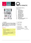
INSTALLATION
MOUNTING: Mount the Flasher so that the maximum amount
of air will for across it, typically in the front passenger side of
the engine compartment.
GREEN WIRE: Connect to a convenient, reliable ground.
Г os
DRIVER SIDE PASSENGER SIDE
FT .
| cur |
Low | HIGH | HIGH LOW
= = = == —
ш 19
“le — lu TO MARKER
= |= a 1 LIGHT WIRE
= |= RED | (OPTIONAL)
Ш | WHITE DRL BLACK À
= |5 COMPATIBLE
Six FLASHER PINK
vy z
LJ
CONTROL | {44 5
SWITCH < ==
= lu DRL
| © 19 OVERRIDE
= (OPTIONAL)
TO C
BATTERY O
PLUS
VEHICLE'S DRL WIRE
CUT
WIRING SCHEMATIC
NOTE
Always connect the green wire FIRST when installing
and disconnect LAST when removing.
BLUE 8: YELLOW WIRE: Locate the wire that supplies power
to the passenger side high beam headlight. Cut this wire
approximately 10" to 12" from the back of the headlight. Con-
nect the Flasher's yellow wire to the wire that returns to the
passenger side high beam. Connect the blue wire to the wire
that returns to the driver side high beam.
RED WIRE: Connect to a user supplied single pole, single
throw switch. Connect the other side of the switch to a 12Vdc
source. This switch will only require a 1/4 amp to activate the
Flasher.
- WHITE WIRE: Connect through an ATO type fuse (20 amp)
to the positive post of the battery. DO NOT USE A CIRCUIT
BREAKER, FUSIBLE LINK OR SLOW BLOW TYPE FUSE.
SPECIALISTS IN EMERGENCY VEHICLE PRODUCTS SINCE 1978 * DESIGN, MANUFACTURING, DISTRIBUTION AND INSTALLATION
NOTE
Older 4 bulb Sealed Beam Headlight Systems may
require a 30 amp fuse. Call Sound Off, Inc.'s Technical
Support Department at 1-800-338-7337 for any further
assistance.
NOTE
DO NOT connect the red and white wires together.
The white wire must receive a constant source of power
at all times.
ORANGE WIRES: Find the DRL input or output wire. "T" or
tap both orange wires into it. Cut the wire between the two
orange wires and tape.
BLACK WIRE (OPTIONAL y: If an "Automatic Nighttime Flasher
Cut off" is required (check State and Municipal regulations),
simply "T" or tap the black wire into the parking light wire. If
not required, connect the black wire to ground.
PINK WIRE (OPTIONAL): Connectto the HOT side of a user
supplied switch, the parking brake switch or the neutral safety
switch. When the pink wire is grounded through one of the
switches, the DRL function and marker light wilt be deacti-
vated.
i
| NON-COMPATIBLE
| FLASHER VEHICLE LIST
i
Buick Century 1997 and Later
Buick Regal 1996 and Later
Chevy Blazer 1998 and Later
Chevy Cavalier 1995 and Later
Chevy CK 1999 and Later
Chevy Malibu 1996 and Later
Chevy S10 1998 and Later
Chrysler Sebring 1997 and Later
Dodge Avenger 1997 and Later
Dodge Durango - 1999 and Later®
Dodge Ram 1999 and Later”
Dodge Dakota 1999 and Later"
Most Japanese Vehicies
Oldsmobile Ciera 1998 and Later
Oldsmobile Cutlass 1998 and Later
Oldsmobile intrigue 1998 and Later
Saturn ALL
“NOTE: 2001 and later Dodge Durango, Dakota and 2002
Dodge Ram 1500-1/2 Ton trucks require a special Dodge
Flasher ET3PFISO0O-P,
WARRANTY
Sound Off, Inc. warranties the ETRROOC, ETPP0OC and
ETQS00C Electronic Flasher Systems for one (1) full year.
from the date of purchase to the original purchaser against
any manufacturer defects or workmanship. This warranty ap-
plies only to units installed according to manufacturer's instal-
lation instructions and operated within the units specifications.
Warranty is void if the unit was installed incorrectly or mali-
ciously damaged.
All warranty claims must be accompanied by a dated proof of
purchase.
Sound Off, Inc. retains the right to be the sole mediator of
what constitutes defects in performance or manufacturing.
Covered under U.S. Patents #4114071 and #4309639