1
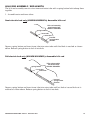
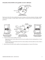
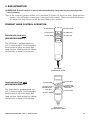
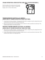
MODEL US0208 / US0208PL SEMI-ELECTRIC BED
MODEL US0458 / US0458PL FULL-ELECTRIC / LOW BED
USER MANUAL
READ THIS MANUAL BEFORE OPERATING THE PATRIOT HOMECARE BED.
SAVE THIS MANUAL FOR FUTURE USE.
NOTE: THE MOST CURRENT VERSION OF THIS MANUAL
CAN BE FOUND ONLINE AT www.grahamfield.com
US0208-INS-LAB-RevB09
CONTENTS
1
SAFETY................................................................................................................................................................................................ 3
WARNING / CAUTION SUMMARY............................................................................................................................................... 3
2
INTRODUCTION, PATRIOT™ HOMECARE BED USER MANUAL..................................................................................................... 4
THERMAL MOTOR PROTECTION............................................................................................................................................... 4
GRAVITY-DOWN FEATURE FOR HEAD AND KNEE ELEVATION............................................................................................. 4
3
ASSEMBLY INSTRUCTIONS............................................................................................................................................................... 5
HEAD AND FOOT ASSEMBLY..................................................................................................................................................... 5
MOTOR ASSEMBLY..................................................................................................................................................................... 6
REMOVE MOTOR SLIDE CAPS........................................................................................................................................... 6
INSTALL MOTORS................................................................................................................................................................ 6
INSTALL MOTOR SLIDE CAPS............................................................................................................................................ 7
MOTOR ASSEMBLY TROUBLESHOOTING......................................................................................................................... 7
FULL-ELECTRIC BED ONLY (US0458/US0458PL): CASTER POSITION................................................................................. 7
STANDARD (CONVENTIONAL) BED HEIGHT..................................................................................................................... 7
LOW BED HEIGHT................................................................................................................................................................ 7
BED END ASSEMBLY.................................................................................................................................................................. 8
FULL-ELECTRIC BED ONLY (US0458/US0458PL): LOCK MOTOR SPRING COUPLING................................................ 8
ALL BED MODELS: ASSEMBLE BED ENDS...................................................................................................................... 8
FULL-ELECTRIC BED ONLY (US0458/US0458PL): ALIGN MOTOR AND GEARBOX...................................................... 9
ALL MODELS: ASSEMBLE HEAD BED END...................................................................................................................... 9
HI/LO ROD ASSEMBLY / BED LENGTH.................................................................................................................................... 10
SEMI-ELECTRIC BED ONLY (US0208/US0208PL): ASSEMBLE HI/LO ROD.................................................................. 10
FULL-ELECTRIC BED ONLY (US0458/US0458PL): ASSEMBLE HI/LO ROD.................................................................. 10
ALL MODELS: ATTACH HI/LO ROD TO GEARBOX OR MOTOR SHAFT PINS...............................................................11
4
BED OPERATION............................................................................................................................................................................... 12
PENDANT HAND CONTROL OPERATION............................................................................................................................... 12
FULL-ELECTRIC BED ONLY (US0458/US0458PL)........................................................................................................... 12
SEMI-ELECTRIC BED ONLY (US0208/US0208PL)............................................................................................................ 12
CRANK OPERATION: SEMI-ELECTRIC BED ONLY (US0208/US0208PL).............................................................................. 13
TRENDELENBURG POSITION, ALL MODELS......................................................................................................................... 13
REVERSE TRENDELENBURG POSITION, ALL MODELS....................................................................................................... 13
5
SPECIFICATIONS, ALL MODELS..................................................................................................................................................... 14
6
ACCESSORIES: BED RAILS............................................................................................................................................................. 15
BED RAIL SAFETY..................................................................................................................................................................... 15
LUMEX® PATRIOT™ LIBERTY BED RAILS................................................................................................................................ 15
GF6500B-1: ASSIST BAR................................................................................................................................................... 15
GF6580B-1: QUARTER RAIL.............................................................................................................................................. 15
GF6590B-1: HALF NO-GAP HEAD RAIL........................................................................................................................... 16
GF6570B-1: FULL LENGTH RAIL....................................................................................................................................... 16
LUMEX® STANDARD BED RAILS.............................................................................................................................................. 16
GF6570A-1: FULL LENGTH SIDE RAIL............................................................................................................................. 16
LX5088: NO-GAP BED RAIL............................................................................................................................................... 17
GF6580A-1: LOW UNIVERSAL HALF RAIL....................................................................................................................... 17
7
SERVICE PARTS, ALL MODELS...................................................................................................................................................... 18
BED COMPONENTS................................................................................................................................................................... 18
BED END COMPONENTS.......................................................................................................................................................... 19
BED SERVICE PARTS................................................................................................................................................................ 20
8
MAINTENANCE AND SAFETY CHECKS.......................................................................................................................................... 21
9
WARRANTY........................................................................................................................................................................................ 22
10 INDEX................................................................................................................................................................................................. 23
• READ THESE INSTRUCTIONS BEFORE OPERATING THE PATRIOT HOMECARE BED
• SAVE THESE INSTRUCTIONS
GF Health Products, Inc. is not responsible for typographical errors. Packaging, warranties, products and
specifications are subject to change without notice.
Graham-Field and Lumex are registered trademarks, and Patriot is a trademark, of GF Health Products, Inc.
© June 2009, GF Health Products, Inc.
US0208-INS-LAB-RevB09 • Patriot™ Homecare Bed
2
1 SAFETY
The safety statements presented in this chapter refer to the basic safety information that the
operator of the Patriot™ Homecare Bed shall pay attention to and abide by. There are additional
safety statements in other chapters or sections, which may be the same as or similar to the following, or specific to the operations. Please note the following special statements, used throughout
this manual, and their significance:
WARNING: Indicates a potential hazard situation or unsafe practice that, if not avoided,
could result in death or serious personal injury.
s Caution: Indicates a potential hazard or unsafe practice that, if not avoided, could result in
minor personal injury or product/property damage.
Note:Provides application recommendations or other useful information to ensure that you get
the most from your product.
WARNING / CAUTION SUMMARY
WARNING: Keep hands and feet clear of all moving parts.
WARNING: Do not allow small children on or near bed during operation.
WARNING: Do not allow this device to be operated by small children.
WARNING: When operating the hi/lo, knee, or back function of the bed, ALWAYS ensure that the
individual confined to the bed is positioned properly within the confines of the bed. DO NOT let any
extremities protrude over the side or between the bed rails when performing any functions.
WARNING: Ensure that body weight is evenly distributed over the surface of the bed. Do not lie, sit
or lean in such a way that your entire body weight is placed only on the raised head or foot sections
of the bed. This includes when assisting the user in repositioning or transferring in or out of bed.
WARNING: The use of non-Lumex® replacement parts and/or bed rails will void the warranty, and could create a hazardous condition resulting in serious personal injury.
WARNING: Before operating, ensure that the bed frame rivets are properly seated in the bed
end hooks; otherwise, injury or damage may result.
WARNING: Keep all moving parts free of obstructions (i.e. blankets/sheets, heating blankets/pads, tubing, wiring, and other types of products).
WARNING: Ensure that End Safety Locking Pins are installed in order to prevent injury
when moving the bed or using a bed-mount trapeze.
WARNING: Warning/Caution labels applied to the bed outline hazards or unsafe practices
that could result in personal injury and/or property damage; do not remove them.
s Caution: The pendant hand control cord must be routed and secured properly to ensure that the
cord does NOT become entangled and eventually severed during use. Ensure that electric cords
DO NOT get tangled around the bed, bed rails or legs during normal operation of the bed.
s Caution: When using nasal or masked type administering equipment, oxygen or air tubing
MUST be routed and secured properly to ensure that tubing does NOT become entangled
and eventually severed during normal operation of bed.
US0208-INS-LAB-RevB09 • Patriot™ Homecare Bed
3
2 INTRODUCTION, PATRIOT™ HOMECARE BED USER MANUAL
This manual contains assembly and maintenance instructions for your Model US0208 / US0208PL
Semi-Electric and US0458 / US0458PL Full-Electric / Low Patriot™ bed. Read the entire manual carefully before using your bed, and refer to it during use if you have questions.
THERMAL MOTOR PROTECTION
This product is powered by a quiet, efficient DC motor system. When the bed is plugged into a
power outlet, the electrical transformer is always energized in a stand-by condition. The Okimat
actuator casing may feel warm to the touch even when the bed is not being used; this is a normal
condition.
Thermal protection activation (protection against overheating caused by excessive or extended
periods of operation), which causes the bed to shut down operation when overheated, is a safety
feature of this product.
Causes of thermal protection activation include multiple or repeated adjustment of long duration,
or the use of multiple functions at one time. To ensure trouble-free operation, always allow a slight
pause between multiple adjustments, and avoid operating more than one function at a time. If
thermal protection activation occurs, the bed pendant hand control will not function. The thermal
protection will reset after a period of time dependent on the severity of the overheating. To shorten the reset time, temporarily unplug the power cord from the power outlet.
GRAVITY-DOWN FEATURE FOR HEAD AND KNEE ELEVATION
Patriot™ beds are equipped with a gravity-down safety feature. The motors push the head and
knee grid decks up, but do not pull the knee and head down. As the motor plunger retracts, the
head and knee lower freely, minimizing bed damage and/or injury from items caught under the
grid deck.
Note: When using telescoping deck-mount bed rails, the head and knee may not lower without
weight on the bed.
US0208-INS-LAB-RevB09 • Patriot™ Homecare Bed
4
3 ASSEMBLY INSTRUCTIONS
HEAD AND FOOT ASSEMBLY
hook
rivet
motor cam
foot
section
hook
head
section
rivet
Assembly, head and foot sections
Note: Grid deck not shown for clarity
1. Lay the head and foot sections on their sides at approximately right angles to each other with
motor cams up, as shown above.
2. Slide the head and foot sections together until the foot section's hook catches the head section’s rivet on both sides. Ensure both rivets are completely seated before continuing.
head wing
linkage plate
head
foot
ten
straigh
Straighten sections
Note: Grid deck not shown for clarity
3. With the rivets fully seated in the hooks as described in step 2, rotate and straighten the bed as
shown above. Position head wing as shown above.
s Caution: While balancing the frame, do not elevate the knee too far or the linkage may overextend and lock. If the linkage locks, manually push the large linkage plate toward the foot
of the bed.
US0208-INS-LAB-RevB09 • Patriot™ Homecare Bed
5
MOTOR ASSEMBLY
WARNING: Assemble motor on bed as follows. While it is possible to
install the motor backwards, avoid it! Incorrect installation could cause
the bed to move in unexpected ways. Note that the motor ends are labeled
and embossed with head and foot symbols (shown at right). Ensure that
bed head and motor head, and bed foot and motor foot, are matched.
Head
Foot
Remove motor slide caps
slide cap
motor
Remove motor slide caps
1. Remove the slide caps from both ends of the motor as shown above. Plungers should be recessed
in motor cavities; if not, operate "down" function on the pendant hand control.
Note:Motor comes from factory with pendant hand control plugged into motor.
2. Install 9V backup battery (not provided) and slide into storage area.
Install Motors
cam
head
foot
tap here
Install motor
3. Hold the bed securely, positioned with motor cams up, as shown above.
4. Position the motor over both cams.
5. Tap either end of the motor housing (shown below) with enough force to snap the motor assembly into position on the cam.
6. Repeat step 5 for other end of motor.
US0208-INS-LAB-RevB09 • Patriot™ Homecare Bed
6
Install motor slide caps
7. Position the caps as shown at right so that
the grooves in the slide cap are aligned with
the grooves in the motor.
8. Apply straight downward pressure to each
end of the cap while sliding into the closed
position.
9. Repeat step 8 for the other cap.
10.Ensure that all four corners of each slide cap
are engaged.
pressure
slide cap
motor
Install motor slide caps
WARNING: Ensure that the motor is assembled on bed as instructed above before use.
Motor assembly troubleshooting
Problems associated with improper motor installation are listed below, with appropriate fix.
Problem
Head operates with knee control button and
knee operates with head control button
Knee lifting linkages bind against grid
deck, preventing knee deck from elevating.
Probable cause
Motor is installed backwards
Fix
Remove motor and reverse it (see page 7)
Motor is installed backwards, enabling
knee to elevate too high and bind linkage
Remove motor and reverse it (see page 7)
FULL-ELECTRIC BED ONLY (US0458/US0458PL): CASTER POSITION
Any full-electric Patriot™ bed can be used as either a standard-height or low-height bed by moving
the casters.
fig 1: casters mounted at
standard height
fig 2: casters mounted at low
height, bed in lowest position
fig 3: casters mounted at low
height, bed in elevated position
Standard (conventional) bed height
To achieve standard bed height, insert casters into outside legs, as shown in fig. 1 above.
Low bed height
To achieve low bed height, insert casters into inner short legs, as shown in figs. 2 and 3 above.
When in the lowest position, the casters are engaged for bed movement, as shown in fig. 2 above.
When elevated, the bed is off the casters and cannot be moved, as shown in fig. 3 above.
Due to the clearances involved, only minor travel and movement are recommended in the low position. The casters can be moved to the outer legs to provide clearance if the bed must be moved
or rolled.
US0208-INS-LAB-RevB09 • Patriot™ Homecare Bed
7
BED END ASSEMBLY
Full-electric bed only (US0458/US0458PL): Lock motor spring coupling
SLIDE IN AND
ROTATE TO
LOCK
ROTATE TO UNLOCK
coupler
Unlocking
coupler
coupler
Locking
coupler
gearbox
gearbox
Before attaching foot end, ensure that hi/lo motor spring coupling is retracted and locked to avoid
interference with end gearbox shaft as shown at above right.
All bed models: Assemble bed ends
1. Insert one locking and one non-locking caster into each bed end. Locking casters must be installed diagonally from each other. See previous page for full-electric caster position options.
2. Standing directly in front of the bed foot end, position it as close to the bed as possible.
3. With one hand, reach over end and lift up the bed.
bed end (foot)
frame (foot)
Attach bed end
4. Tilt the bed end slightly back toward you as shown above.
rivet
lock
Engage lower rivet
Lower bed onto lock
5. Engage lower rivet slightly with corner lock and tilt end toward bed as shown at above left.
6. Lower bed onto corner lock as shown at above right.
US0208-INS-LAB-RevB09 • Patriot™ Homecare Bed
8
7. After bed ends have been attached, install bed end safety
pins to act as safety latches.
(Bed End Safety Pin Kit part number: 690-1000-100; includes
four clevis pins, four hitch pins and four washers). A lanyard is supplied to attach hardware to the bed or the end
upon disassembly.
Insert pins and washer as shown at right, with flat washer
on outside of bed end hook. Bed end safety pins, while not
necessary for normal bed operation, will prevent the bed
ends from accidentally rolling off when moving or pushing
the bed, or while installing or using bed-mount trapezes.
washer
bed end
hook
Install bed end safety pins
Full-electric bed only (US0458/US0458PL): Align motor and gearbox
After installing foot end, you may have to shift bed frame slightly in bed end hooks to ensure
proper horizontal alignment with motor coupling and end gearbox shaft.
When coupling and shaft are aligned, unlock spring-loaded coupling. Coupling may not snap into
groove until motor is rotated with pendant hand control after bed is assembled.
HEAD
FOOT
Route cord under cross-angle
Plug hi/lo motor into Okimat actuator assembly, being careful to route cord under the fixed base
frame cross-angle as shown above to ensure clearance with hi/lo drive shaft. The motor plug is
located next to the pendant hand control plug on the actuator.
All models: Assemble head bed end
8. Repeat steps 1-7 for head bed end.
US0208-INS-LAB-RevB09 • Patriot™ Homecare Bed
9
HI/LO ROD ASSEMBLY / BED LENGTH
The hi/lo rod assembly consists of an inner and outer tube with a spring button lock to keep them
together.
1. Assemble outer and inner tubes:
Semi-electric bed only (US0208/US0208PL): Assemble hi/lo rod
spring button
Hi/lo rod assembly
semi-electric bed
US0208 / US0208PL
inner tube
outer tube
inserted
spring button
position
Depress spring button and insert inner tube into outer tube until third hole is reached as shown
above. Release spring button to lock it into hole.
Full-electric bed only (US0458/US0458PL): Assemble hi/lo rod
spring button
Hi/lo rod assembly
full-electric bed
US0458 / US0458PL
inner tube
outer tube
inserted
spring button
position
Depress spring button and insert inner tube into outer tube until last hole of second hole set is
reached as shown above. Release spring button to lock it into hole.
US0208-INS-LAB-RevB09 • Patriot™ Homecare Bed
10
All models: Attach HI/LO rod to gearbox or motor shaft pins
gearbox shaft
(or motor shaft)
pin
hi/lo rod
slot
Attach hi/lo rod to
gearbox or motor shaft
Both ends of the hi/lo rod assembly have a slot to mount on the foot end motor shaft pins and bed
end gearbox shaft pins as shown above. Follow steps 2-3 to mount the hi/lo rod assembly on the
gearboxes.
hi/lo
motor shaft
foot end
hi/lo rod
assembly
head end
FOOT END
foot end gearbox
Fig 1: Semi-Electric Bed:
Attach hi/lo rod assembly
to foot end gearbox
head end gearbox
Fig 2: Full-Electric Bed:
Attach hi/lo rod assembly
to foot end hi/lo motor shaft
Fig 3: All Bed Models:
Attach hi/lo rod assembly
to head end gearbox
2. Connect the hi/lo rod assembly to the bed.
Semi-electric bed: Attach either end of hi/lo rod assembly to the foot end gearbox as shown
in Fig 1 above.
Full-electric bed: Attach either end of hi/lo rod assembly to the foot end hi/lo motor shaft as
shown in Fig 2 above.
3. Attach other end of hi/lo rod assembly to head end gearbox as shown in Fig 3 above.
US0208-INS-LAB-RevB09 • Patriot™ Homecare Bed
11
4 BED OPERATION
WARNING: Ensure that bed is secure and assembled as instructed on previous pages before operating.
Note:In the event of a power failure, use a standard 9V battery to lower the bed's head and foot
sections (the 9V battery connection is attached to the motor). When used with the battery,
the motor will only lower, not lift, the head and/or foot sections.
PENDANT HAND CONTROL OPERATION
Full-electric bed only
(US0458/US0458PL)
to raise head
to lower head
to raise foot
to lower foot
to raise bed
to lower bed
The full-electric pendant hand control is shown at right. Use the pendant
hand control to raise and lower bed,
head and foot. Each button has a different function, as noted in the picture.
Full-electric
pendant hand control
Semi-electric bed only
(US0208/US0208PL)
The semi-electric pendant hand control is shown at right. Use the pendant
hand control to raise and lower bed
head and foot. Each button has a different function, as noted in the picture.
to raise head
to lower head
and foot at the
same time
to lower head
to raise foot
to raise head
and foot at the
same time
to lower foot
Semi-electric
pendant hand control
US0208-INS-LAB-RevB09 • Patriot™ Homecare Bed
12
CRANK OPERATION: SEMI-ELECTRIC BED ONLY (US0208/US0208PL)
Use the crank at the center foot of the semielectric bed (shown at right) to change bed
height (raise or lower entire deck).
foot
crank
Crank operation
TRENDELENBURG POSITION, ALL MODELS
(HEAD END AT LOWER ELEVATION THAN FOOT END)
1. Lower bed to its lowest height. Disengage the hi/lo rod by compressing the spring button and
removing the hi/lo rod from the motor or bed end.
2. Raise the foot bed end using the pendant hand control or crank (semi-electric bed only). The
head end will remain in the low position.
REVERSE TRENDELENBURG POSITION, ALL MODELS
(HEAD END AT HIGHER ELEVATION THAN FOOT END)
1. Raise bed to its highest height. Disengage the hi/lo rod by compressing the spring button and
removing the hi/lo rod from the motor or bed end.
2. Lower the foot bed end using the pendant hand control or crank (semi-electric bed only). The
head end will remain in the high position.
US0208-INS-LAB-RevB09 • Patriot™ Homecare Bed
13
5 SPECIFICATIONS, ALL MODELS *
* Specifications are subject to change without notice.
Deck
height
High position
Deck height: High Position
US0208/US0208PL:
24.0 inches
US0458/US0458PL with casters in low position: 20.0 inches
US0458/US0458PL with
casters in standard position:
23.5 inches
Low position
Deck height: Low Position
US0208/US0208PL:
15.0 inches
Bed length
US0458/US0458PL with casters in low position: 9.5 inches
US0458/US0458PL with
casters in standard position:
13 inches
Bed Length
Note: To extend grid length (80
in.) to 84 in., install optional kit
690-0084-000
(all beds).
All models: 87.0 inches
Deck width
Weight *
Construction
Finish
Deck Width
All models: 36.0 inches
Normal operating conditions
450 lb., evenly distributed including mattress, accessories, rails, etc.
* Maximum patient weight
Frame
Sleeping surface
5 stage bath
350 lb.
10 ga (.135) high strength, low alloy steel (roll formed)
11 ga (.120) cold rolled steel
1. S21F acid bath (cleans grease and oil from metal).
2. Fresh water rinse.
3. QuiliPhos 20 phosphate coat (inhibits rust and helps maintain
electrical charge during powder application).
4. Fresh water rinse.
5. QuiliRinse 404 (seals metal for powder coating).
All parts are then coated with a colored epoxy powder and baked 35 minutes at 375 degrees F. The
powder coating finish is approximately 2.5 mils thick. The coating is smooth, uniform finish without
runs, wrinkles, or grit.
US0208-INS-LAB-RevB09 • Patriot™ Homecare Bed
14
6 ACCESSORIES: BED RAILS
Patriot™ Homecare Bed decks are equipped with patent-pending slots specifically for bed rail
installation, providing a fixed place to mount GF bed rails. Two styles of Lumex® bed rails are described in Section 6:
1) The Patriot™ Liberty bed rail system, designed specifically for Patriot™ Beds, and
2) Standard Lumex® bed rails
Please read the following bed rail safety information.
BED RAIL SAFETY
WARNING: If bed rails are not properly installed and adjusted, personal injury and/or damage to the bed rail could result.
For information on bed rail safety, please see the following brochure: "A Guide to Bed Safety: Bed Rails in Hospitals, Nursing Homes and Home Health Care: The Facts" on the FDA's
web site, at http://www.fda.gov.cdrh/beds/
WARNING: The use of non-Lumex® replacement parts and/or bed rails will void the warranty, and could create a hazardous condition resulting in serious personal injury.
WARNING: GF Health Products, Inc. assumes no responsibility for any damage or injury
caused by improper installation of bed rails or unauthorized bed rail use. Only Lumex® bed
rails are recommended for use with Patriot™ beds. Please consult the instructions that accompany your Lumex® bed rails for complete rail assembly and installation instructions.
LUMEX® PATRIOT™ LIBERTY BED RAILS
Lumex® Patriot™ Liberty Bed Rails are designed specifically for use with Lumex® Patriot™ Beds.
Developed using the FDA Hospital Bed System Dimensional Guidance to Reduce Entrapment
and tested to the Hospital Bed Safety Workgroup and FDA Dimensional Test Methods for Bed
System Zones 1-4 and International Standard IEC60601-2-38 Requirements for the Safety of
Electrically Operated Hospital Beds, Lumex® Patriot™ Liberty Bed Rails offer added protection
and reduce the risk of entrapment. For installation of these FDA compliant-bed rails, follow the
installation instructions that accompany them. Patriot™ Liberty Bed Rail descriptions follow.
GF6500B-1: Assist Bar
A secure handhold and support for active patients
who need assistance getting in and out of bed on
their own, this bar is bolted directly to either side
of the bed frame to support the split frame when a
patient enters or exits the bed. It can also assist patients capable of grasping the bar and maneuvering
themselves with rotating and turning in bed.
GF6500B-1
Assist Bar
GF6580B-1: Quarter Rail
The Quarter Rail, approximately 18 inches in length when mounted on
the Patriot™ bed, can be used as a head assist, head rail, or foot rail.
GF6580B-1
Quarter Rail
US0208-INS-LAB-RevB09 • Patriot™ Homecare Bed
15
GF6590B-1: Half No-Gap Head Rail
The Half No-Gap Head Rail, which provides
a full head coverage of 31.5 inches, extends
to eliminate the gap between the head board
and the end of the rail. The GF6590B-1 mounted on the bed's head and the GF6580B-1
mounted on the bed's foot combine to create
the Patriot™ split rail system.
GF6590B-1
Half No-Gap Head Rail
GF6570B-1: Full Length Rail
The Full Length rail is a nominal, telescoping
full length rail that provides maximum length
rail perimeter coverage.
GF6570B-1
Full-Length Rail
LUMEX® STANDARD BED RAILS
If you install Lumex® standard bed rails, follow the installation instructions that accompany them;
the following instructions are provided to describe the differences between the installation of bed
rail crossbraces on Patriot™ grid beds and spring beds.
WARNING: Do not use the bed rails as handles for getting into or out of bed; this could result in personal injury and damage to the bed rails.
HEADBOARD
FOOTBOARD
GF6570A-1: Full Length Side Rail
GF6570A-1
Full-Length Side Rail
A
A
G1
Spring Buttons
G4
Position spring-loaded crossbraces #A into slots G1 and G4 on both sides of bed with spring buttons facing inward as shown above.
US0208-INS-LAB-RevB09 • Patriot™ Homecare Bed
16
HEADBOARD
FOOTBOARD
LX5088: No-Gap Bed Rail
LX5088
No Gap Side Rail
B
G2
Spring Buttons
G3
B
Position spring-loaded crossbraces #B into slots G2 and G3 on both sides of bed with spring buttons facing inward as shown above.
GF6580A-1: Low Universal Half Rail
Cable tie
GF6580A-1
Low Universal Half Rail
Secure crossbrace
to head deck angle
with cable tie
HEADBOARD
B
SUGGESTED
RAIL TO HEADBOARD
MINIMUM OF 9.25"
Follow same
procedure
for mounting
half rails on
foot-end using
G3 slots.
Spring Buttons
G2
FOOTBOARD
A
G3
Head end: Position spring-loaded crossbrace #B into slots G2 on both sides of bed. Position crossbrace #A so that the stabilizer rests underneath the head deck angle. Secure the crossbrace to the
head deck angle with a cable tie. Ensure spring buttons face inward as shown above.
Note: Suggested rail-to-headboard minimum is 9.25 inches.
Foot end: Position spring-loaded crossbrace #B into slots G3 on both sides of bed. Position crossbrace #A so that the stabilizer rests underneath the foot deck angle. Secure the crossbrace to the
foot deck angle with a cable tie. Ensure spring buttons face inward as shown at head end above.
US0208-INS-LAB-RevB09 • Patriot™ Homecare Bed
17
7 SERVICE PARTS, ALL MODELS
Service parts for all bed models are shown below and on the following two pages. See pictures and
tables for appropriate service parts.
Note:To order service parts, contact our Customer Service department at 800-365-2338 (fax
920-929-8213).
BED COMPONENTS
HEAD
FOOT
Part number
690-7100-901
690-7105-902
690-7104-902
690-7001-000
690-7601-000
690-7004-000
690-7604-000
Description
Head section, includes hi/lo rod
Foot section, semi-electric, includes motor
Foot section, full-electric, includes motors
End set, semi-electric, walnut panels
End set, semi-electric, plastic panels
End set, full-electric, walnut panels
End set, full-electric, plastic panels
US0208-INS-LAB-RevB09 • Patriot™ Homecare Bed
Semi-electric
US0208
X
X
Full-electric
US0208PL
X
X
US0458
X
US0458PL
X
X
X
X
X
X
X
18
BED END COMPONENTS
HEAD
5
6
FOOT
8
2
7
Item Part number
1
2
3
4
5
690-7001-901
690-7601-901
690-7004-901
690-7604-901
690-7001-902
690-7601-902
690-7004-902
690-7604-902
999-0301-904
100-6330-014
100-6330-015
100-4200-012
554-2001-015
690-5001-025
690-5004-015
690-5004-025
6
7
8
9
554-2001-059
690-5004-059
600-2001-912
600-2001-916
999-0353-000
600-2001-910
690-1000-100
3
4
Description
Head bed end, semi-electric, walnut panels
Head bed end, semi-electric, plastic panels
Head bed end, full-electric, walnut panels
Head bed end, full-electric, plastic panels
Foot bed end, semi-electric, walnut panels
Foot bed end, semi-electric, plastic panels
Foot bed end, full-electric, walnut panels
Foot bed end, full-electric, plastic panels
Caster, set of 4: 2 locking & 2 non-locking
Caster, non-locking, each
Caster, locking, each
Caster socket, each
End panel, head/foot, semi-electric, walnut
panels
End panel, head/foot, semi-electric, plastic
panels
End panel, head/foot, full-electric, walnut
panels
End panel, head/foot, full-electric, plastic
panels
Capping, bed end, head/foot, semi-electric
Capping, bed end, head/foot, full-electric
Foot elbow, full-electric
Foot elbow with crank, semi-electric
Foot crank only, semi-electric
Elbow, head end, semi-electric & full-electric
End locking hardware and lanyard, set of 4
(not shown)
US0208-INS-LAB-RevB09 • Patriot™ Homecare Bed
1
Semi-electric
US0208
X
Full-electric
US0208PL
US0458
US0458PL
X
X
X
X
X
X
X
X
X
X
X
X
X
X
X
X
X
X
X
X
X
X
X
X
X
X
X
X
X
X
X
X
X
X
X
X
X
X
X
X
X
X
X
X
X
19
BED SERVICE PARTS
HEAD
FOOT
1
4
2
3
Item Part number
1
2
3
4
5
690-2001-913
690-2001-411
690-2001-410
690-3001-943
690-2001-414
690-3001-415
690-7001-944
690-3001-941
554-2018-901
690-2001-412
690-1000-100
Description
Motor and pendant, semi-electric
Pendant, semi-electric
Motor, semi-electric
Motor and pendant, full-electric
Pendant, full-electric
Motor, full-electric
Motor and bracket, hi/lo
Motor, hi/lo, full-electric
Hi/lo rod assembly
Motor slide covers
End locking hardware and lanyard, set of 4
(not shown)
Semi-electric, H7920SE
Full-electric, H7920FE
US0208 / US0208PL
X
X
X
US0458 / US0458PL
X
X
X
X
X
X
X
X
X
X
X
Note:US0208 and US0208PL are identified on the foot section component label as
Patriot™ Semi-Electric Bed Model H7920SE.
Note:US0458 and US0458PL are identified on the foot section component label as
Patriot™ Full-Electric Bed Model H7920FE.
US0208-INS-LAB-RevB09 • Patriot™ Homecare Bed
20
8 MAINTENANCE AND SAFETY CHECKS
Perform the following as needed or between patient placements, whichever happens sooner:
Electronics and
Motors
Bed frames and
sleeping surface
Cleaning
Lubrication and
mechanical
Check all controls to ensure that all functions work
properly.
Foot control
Head control
Hi/Lo (if applicable)
Check all cables for damaged or frayed wires.
Power cord
Pendant hand control cord
Check to ensure that all plugs are fully inserted or attached.
Check to ensure that all wires are routed and attached properly so not to interfere with any moving parts.
Inspect motor casings for excessive wear and cracks
Inspect motor slide caps for excessive wear and deformation
Visually check all welds
Head section
Foot section
Main Frame
Check joints between sleeping surface sections for loose fasteners.
Inspect frames and sleeping surface for bending and excessive wear
The metal parts of the bed are covered with a powder coating. Clean all coated parts with mild detergent
and warm water. Periodically raise head and foot sections of the bed and remove dust from frame. Also,
periodically remove mattress and clean mattress deck.
Lubricate all caster roller and swivel bearings with light machine oil.
Check all bolts and tighten as needed.
US0208-INS-LAB-RevB09 • Patriot™ Homecare Bed
21
9 WARRANTY
GF Health Products, Inc. warrants the
Patriot™ US0208 / US0208PL Semi-Electric Homecare Bed
Patriot™ US0458 / US0458PL Full-Electric / Low Bed
as follows:
● Two year warranty for defects in workmanship and materials of mechanical components,
frame, and electronics.
● During the warranty period, defective items will be repaired or replaced at manufacturer's option. The warranty does not include any labor charges incurred in replacement part(s) installation or any associated freight or shipping charges to the manufacturer.
US0208-INS-LAB-RevB09 • Patriot™ Homecare Bed
22
10 INDEX
A
Assembly instructions 5
B
Bed end assembly 8
Bed end safety pins, install 9
Bed extension kit, 84" 14
Bed height, low, full-electric 7
Bed height, standard, full-electric 7
Bed length adjustment 10
Bed operation 12
Bed rails 15
Bed rail safety 15
C
Caster position (full-electric bed only) 7
Caution statement, significance 3,?5
Crank operation (semi-electric bed only) 13
D
Deck height (high position) 14
Deck height (low position) 14
P
Pendant hand control operation, full-electric 12
Pendant hand control operation, semi-electric 12
Power failure; battery operation 12
S
Service parts, all models 18
Service parts, bed components 18
Service parts, bed end components 19
Specification, construction 14
Specification, weight 14
Specifications, dimensions 14
T
Thermal motor protection 4
Trendelenburg position 13
Trendelenburg position, reverse 13
W
WARNING statement, significance 3
Warranty 22
F
Full-electric 10
H
Head and foot assembly instructions 5
Hi/lo rod assembly 10
I
Introduction 3
L
Lumex® Patriot™ Liberty bed rails 15
Lumex® standard bed rails 16
M
Maintenance, bed frame and sleeping surface 21
Maintenance, cleaning 21
Maintenance, electronics 21
Maintenance, lubrication and mechanical 21
Maintenance and safety checks 21
Motor assembly 6
Motor assembly troubleshooting 7
Motor slide caps, install 7
Motor slide caps, remove 6
N
Non-Lumex® bed rails 15
Non-Lumex® replacement parts 15
Note, significance 3
US0208-INS-LAB-RevB09 • Patriot™ Homecare Bed
23
U.S.A. Corporate Headquarters:
GF Health Products, Inc.
2935 Northeast Parkway
Atlanta, Georgia 30360
telephone: 800-347-5678, 770-447-1609
fax: 800-726-0601, 678-291-3232
www.grahamfield.com