1
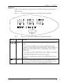
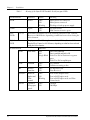
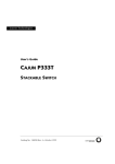
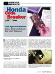
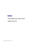
Lucent Technologies
Installation Guide
Cajun P115G
STACKABLE WORKGROUP SWITCH
Cat No. 130008 Rev.0 September 1998
.
Preface
Important information
SAFETY PRECAUTIONS
CAUTION – TO REDUCE THE RISK OF ELECTRIC SHOCK AND FIRE
1. All servicing should be undertaken ONLY by qualified personnel. The parts inside the unit
CANNOT be serviced or repaired by the end user. Please call your service representative for
assistance.
2. Do NOT plug in, turn on or attempt to operate a damaged unit.
3. Ensure that the chassis ventilation slots in the unit are NOT BLOCKED.
4. Replace a “blown” fuse only with the same type and rating as is marked on the safety label
adjacent to the power inlet housing the fuse.
5. DO NOT operate the unit in a location where the maximum ambient temperature exceeds
40ºC.
6. Be sure to unplug the power supply cord from the wall socket BEFORE attempting to remove
and/or check the main power fuse.
PRECAUTIONS DE SECURITÉ
AVERTISSEMENT – POUR RÉDUIRE LE RISQUE DE CHOC ÉLECTRIQUE ET D’INCENDIE
1. Tout entretien doit être fait UNIQUEMENT par un personnel de service qualifié. Aucun
élément ne peut être réparé par un particulier.
2. NE PAS brancher, allumer ou essayer de faire fonctionner une unité sur laquelle un doute
existe quant à son bon fonctionnement.
3. S’assurer que les ouvertures d’aération du châssis dans l’appareil NE SONT PAS
OBSTRUEES.
4. Remplacer un fusible défaillant UNIQUEMENT par un modèle du même type suivant les
recommandations indiquées sur l’étiquette de securité posée dans le logement du fusible.
5. NE PAS faire fonctionner l’appareil dans un endroit où la temperature dépasse les 40ºC.
6. S’assurer de débrancher l’alimentation électrique AVANT toute manipulation sur le fusible
principal.
SICHERHEITSVORKEHRUNG
ACHTUNG – ZUR VERHINDERUNG DES RISIKOS VON ELEKTRISCHEM SCHLAG UND FEUER
1. Die Geräte enthalten keine Bauteile, die außerhalb des Lucent Servicezentrums gewartet oder
repariert werden können. Die Wartung darf NUR von qualifiziertem, technischem Personal
durchgeführt werden.
2. NIEMALS ein beschädigtes Gerät einschalten, oder versuchen es zu bedienen.
3. Vergewissern Sie sich, dass die Chassis Ventilationsöffnungen des Gerätes NICHT
BLOCKIERT sind.
Cajun P115G Stackable Switch Installation Guide
1
Preface
4.
5.
6.
2
Safety Instructions
Austauschen einer durchgebrannten Sicherung NUR mit der gleichen Sorte und Belastbarkeit
wie sie auf der Sicherheitsaufschrift markiert ist. Die Aufschrift befindet sich neben der
Stromzufuhr wo sich auch der Sicherungskasten befindet.
Bedienen Sie das Gerät NICHT an einer Stelle an der die Umgebungstemperatur 40ºC
übersteigt.
Ziehen Sie das Netzkabel raus, BEVOR Sie versuchen die Hauptsicherung zu kontrollieren
oder auszutauschen.
Cajun P115G Stackable Switch Installation Guide
Chapter 1
Overview
This guide is divided into two sections:
• Overview: A general description of the features of the Lucent Technologies’
Cajun™ P115G Stackable Switch.
• Installation: Instructions for getting the Cajun P115G Stackable Switch and Cajun
P110 hub stack up and running.
Description
The Cajun P115G Stackable Switch is part of the Cajun P110 Switching System family
of workgroup switches. The Cajun family is composed of high-performance workgroup
switches, which may be used singly or stacked in any combination to make up a multiprotocol, non-blocking, scalable switch.
The Cajun P115G is a workgroup switch with 24 ports divided into three shared
groups and an additional Ethernet/Fast Ethernet uplink port which can be either
copper or fiber-optic. The three groups consist of eight Ethernet/Fast Ethernet
(10/100BASE-T) ports each. The shared ports are ideal for workgroup connectivity,
while the uplink port can be used for high performance workstations or uplink.
When operated as part of a stack, a Cajun P110 NMA to manage the switches. The
units are physically linked using the Cajun P110 Exoplane™, which makes up a multigigabit, non-blocking backplane. Any combination of two, three or four Cajun switches
can be stacked, and up 32,000 MAC addresses per stack are supported.
The uplink port can run at full or half duplex. Shared ports run in half duplex mode
only, and setting the speed (10 or 100 Mbps) operates at group level. With a Cajun
P110 NMA installed, the UTP uplink port can perform standards-based autonegotiation. Redundancy on the uplink ports can be defined via CajunView, Lucent
Technologies’ SNMP-based management system. A redundant power supply may be
used for enhanced fault tolerance.
The Cajun P115G uplink port can use Lucent’s flow control mechanism to eliminate
packet loss. An automatic fairness mechanism ensures that all ports gain fair access to
the Cajun P110 Exoplane, even at very high network utilization. Congestion
management works both on full and half duplex ports, and ensures no packet loss
should the buffers become saturated during peak load conditions.
Cajun switches are fully manageable, using CajunView™, and may be monitored using
the SMONMaster™ Switch Monitoring Application.
Cajun P115G Stackable Switch Installation Guide
3
Chapter 1
4
Description
Cajun P115G Stackable Switch Installation Guide
Chapter 2
Installation
Setting the DIP switches
First, set the DIP switches. The drawing below shows the default positions of the DIP
switches on the rear panel of the Cajun P115G.
Figure 1
The Cajun P115G Stackable Switch Rear Panel Showing the DIP
Switches in their Default Positions
The DIP switches control the three groups of eight 10/100 Mbps ports and the uplink
port. The ports can also be controlled by CajunView, or any SNMP network
management application via the Cajun P110 NMA. A detailed explanation of the DIP
Switches follows.
• USE SW (Use Switches): Selects whether the 10/100 mode will be controlled from
the management station or by the DIP switches.
When set to ON, 10/100 Mbps switch and uplink settings are determined by the
DIP switches only. Settings can be monitored, but not changed, by the management
station.
When set to OFF, the DIP switch settings are ignored and the 10/100 Mbps port
and uplink functionality are controlled from the management station via the Cajun
P110 NMA.
Set to ON when you do not have SNMP management, or when you want to
ensure that the settings cannot be changed through management.
Notes:
• In standalone mode (that is, with no Cajun P110 NMA installed), the 10/100 mode
is always controlled via DIP switches 100M 1-8, 100M 9-16, and 100M 17-24,
irrespective of the position of the USE SW DIP switch.
• Configure all ports to 100M unless they are specifically used in 10M mode.
• Always reset the unit after changing switch configurations.
Cajun P115G Stackable Switch Installation Guide
5
Chapter 2
Installation
•
•
•
100M 1-8, 100M 9-16, and 100M 17-24: Selects whether the port groups will
operate at 10 Mbps or 100 Mbps.
100M: Selects whether the copper uplink port will operate at 10 Mbps or
100 Mbps.
FDX: Selects whether the uplink will operate at full or half duplex mode.
Note: FDX with Flow Control is supported for the uplink port only when a Cajun
P110 NMA is present.
•
FX: Selects whether the uplink is through a fiber-optic line or a copper line.
Note: Only the Ethernet uplink port can operate in full duplex mode. The 24
individual ports can only be used in half duplex mode.
Table 1
DIP Switches on the Cajun P115G Stackable Switch
Switch
Function
ON
OFF
USE SW
(Use Switches)
Selection of operational mode:
control by management
station or DIP switches.
Ignore
management
settings.
Use switches.
Use management
settings.
Ignore switches.
100M 1-8,
100M 9-16,
and 100M
17-24 Switches
Selection of port speed
100 Mbps
10 Mbps
100M
Selection of uplink speed for
copper port only.
100 Mbps
10 Mbps.
FDX
Selection of uplink Half/Full
Duplex mode.
Full duplex
Half-duplex
FX
Selection of fiber optic or
copper line on uplink port.
Fx
Tx
(right-most
switch)
Not used
The shaded cells show the default settings for the DIP switches.
Once you have set the switches, you may proceed with the physical installation of the
hub.
6
Cajun P115G Stackable Switch Installation Guide
Chapter 2
Installation
Installing the Cajun P115G Stackable Switch
The procedure for getting the Cajun P115G Stackable Switch up and running depends
on whether the hub is to operate standalone or as part of a stack.
First, attach the adhesive rubber legs to the base of the Cajun switch. If the switch is
to be rack mounted, do not attach the legs.
Standalone Operation - Plug ‘n’ Play
Getting the Cajun hub working is quick and easy:
1. Connect the power cable to the hub,
2. Connect the cables to the front panel ports,
To ensure proper ventilation, ensure that the Cajun P110 NMA slot is closed.
The hub is now fully operational. By default, all ports will operate as 100 Mbps ports,
in half-duplex mode. Port speed can be changed using the DIP switches
Stacked Operation
To make the Cajun P115G work as part of a stack (or to give SNMP management
capabilities to a single Cajun P115G), a Cajun P110 NMA with software version 8.4 (or
higher) is required. See the Release Notes for the required version.
You should make sure the Cajun P110 NMA has the latest agent software. To check
what software version you have, see the agent configuration window in CajunView (on
UNIX), or see the setup main menu of the Cajun P110 NMA.
1. Before adding a switch to the Cajun P110 stack, turn off the main power to the
stack, by individually unplugging each hub.
2. Place the Cajun P110 NMA in the top hub of the stack.
3. If the Cajun P110 NMA contains the latest software version, go to step 4.
If the Cajun P110 NMA does not contain the latest agent software, you should
perform a software download of the latest version. The latest software version is
always shipped with the Cajun P110 NMA.
Download is performed via FTP using a Terminal console or via CajunView –
details can be found in the Cajun P110 NMA installation Guide.
Cajun P115G Stackable Switch Installation Guide
7
Chapter 2
Installation
Note: Configuration parameters will be set back to factory defaults if they were set
using the management station. The factory default parameters are described in the
Cajun P110 NMA 8.4 Release Note.
4.
5.
Place the Cajun P115G and any other additional Cajun P110 hubs in the stack.
Connect Cajun hubs using the Cajun P110 Exoplane cables, as shown in Figure 2.
A hub connects to its upper neighbor through two Exoplane cables, and to its
lower neighbor through another two Exoplane cables.
Make sure that the Cajun P110 Exoplane cables are correctly seated by gently
exerting pressure on the back of the connector.
Cabling Requirements:
8
•
When using the Cajun P115G, P116T, P114T or P114F in the stack, make sure
all switches in the stack are connected using Cajun P110 Exoplane cables with
white connectors and marked C/S:B or higher (part number 4705-019). Extra
cables can be ordered from your local Lucent Technologies representative.
•
The Cajun P110 Exoplane link (which consists of two cables for connecting a
Cajun unit to a stack) is not included with the Cajun P115G. You need to order
the Exoplane link separately (part number 4705-019). The Cajun P110 NMA is
provided with its own Exoplane link and terminators.
Cajun P115G Stackable Switch Installation Guide
Chapter 2
Figure 2
6.
7.
8.
Installation
Rear View of a Cajun P110 Stack, Showing how the Units are linked via the
Cajun P110 Exoplane Cables. A Cajun P110 NMA Resides in the Uppermost
Unit.
Two terminators are supplied with the Cajun P110 NMA. Insert the two
terminators into the lowest two connectors at the bottom of the stack, as shown in
Figure 2.
Turn on the mains power to the stack, by individually plugging in each hub.
Connect the cables to the front panel ports.
Notes:
•
If the Cajun P110 NMA in the stack contains software version 8.4 or higher, the
stack is now fully operational.
•
When a new version of the Cajun P110 NMA software becomes available, you
should perform software download to benefit from the extra capabilities
provided. See the Cajun P110 NMA Installation Guide for details.
Note: When a Cajun P110 switch is added to, removed from or swapped in a stack,
all Ethernet port settings (Administration Status, Port Mode, port speed and VLANs)
will return to their default values.
Cajun P115G Stackable Switch Installation Guide
9
Chapter 2
Installation
Rack Mounting
Cajun switches slot into a standard 19 inch rack.
Remove the rubber legs from the base of any switch that is to be rack mounted.
Place the switches in the rack, as follows:
1. Snap open the ends of the front panel to reveal the fixing holes.
2. Insert the switches into the rack so that the switches in a logical stack lie directly
on top of each other. Ensure that the Cajun screw holes are aligned with the rack
hole positions exactly as shown in figure 3. Stacking them in this way will allow
the switches to be easily connected using the Cajun P110 Exoplane cables.
3. Secure the switches in the rack using the screws. Use one screw on each side. Do
not overtighten the screws in order not to damage the plastic.
4. Connect the Cajun P110 Exoplane cables, as described above, and as illustrated in
Figure 2.
5. Snap closed the hinged ends of the front panel.
Figure 3
10
Cajun rack mounting arrangement
Cajun P115G Stackable Switch Installation Guide
Chapter 2
Installation
Diagnostics
Tables 2 and 3 explain the meaning of the Cajun P115G Stackable Switch diagnostic
LED indicators.
Button
Figure 4
The Cajun P115G Stackable Switch Front Panel LEDs and Buttons
Table 2
Meaning of the Cajun P115G Stackable Switch Front Panel Buttons
Function
Meaning
Select
The buttons determine what function will be displayed by the Port
LEDs.
The five Function LEDs (above the Select buttons) show which
function is currently displayed by the Port LEDs. The Port LEDs can
display either Link, Collision, Receive, Full Duplex, Flow Control or
100 M status
If, for example, the Link (LNK) LED is lit then LEDs 1 to 24 and the
uplink LED will display the Link status of every port.
Press the left or right button to toggle the Port LED display between
functions
Reset
Press and hold both buttons simultaneously for a second or more to
reset the entire Cajun P110 stack. Upon reset, all LED indicators turn
on. Resetting the unit does not affect configuration settings.
Cajun P115G Stackable Switch Installation Guide
11
Chapter 2
Installation
Table 3
Meaning of the Cajun P115G Stackable Switch front panel LEDs
LED Indicator
Function
Status
Meaning
PWR
Power
OFF
ON
Blinking
Mains power not connected
Mains power connected
Working on back-up power supply
NMA
Agent
OFF
ON
No agent in hub
Hub contains an active agent
Port
LEDs
1 to 24
Uplink
LED
Each LED can display one of the following functions: Link, Collision,
Receive or 100 M states, depending on what has been selected using the
Select buttons.
Displays one of the following functions: Link, Collision, Receive, Full
Duplex/Flow Control, or 100 M states, depending on what has been selected
using the Select buttons.
Function LED
12
Port LED
LNK
Link status
OFF
ON
Single Blink
Port is not connected.
Port is enabled and link is OK
Link Test Fail or Partition in segment
ports.
Link Test Fail on uplink port.
COL
Collision
OFF
ON
No Collision
Collision occurring on line
Rx
Receive
from line
OFF
ON
No Data Received
Data Received
FDX/FC
Half/Full
duplex and
Flow
control
OFF
ON
Blinking
Port in Half Duplex mode
Port in Full Duplex mode
Port in Full Duplex mode and Flow
Control mode
100 M
Uplink or
Group port
speed
OFF
ON
10 Mbps
100 Mbps
Cajun P115G Stackable Switch Installation Guide
Chapter 2
Installation
Management Application Notes
1.
2.
When a segment port is disabled, the whole segment is disabled.
A disabled port reports its link as okay, regardless of its status.
Cajun P115G Stackable Switch Installation Guide
13
Lucent Technologies Inc.,
Data Networking Systems,
211 Mt. Airy Rd., Basking Ridge,
NJ 07920.
Cajun and Cajun View are trademarks, and in some jurisdictions may be registered trademarks of Lucent Technologies or
its affiliated companies. Other trademarks appearing in this document are the property of their respective owners.
© Copyright 1998 Lucent Technologies. All rights reserved.