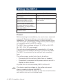
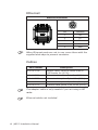
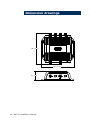
1
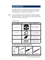
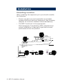
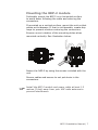
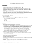
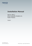
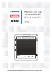
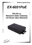
Manual
Network Expansion Port 2
NEP-2
English
www.lowrance.com
www.simrad-yachting.com
Brands by Navico - Leader in Marine Electronics
Disclaimer
As Navico is continuously improving this product, we
retain the right to make changes to the product at any
time which may not be reflected in this version of the
manual. Please contact your nearest distributor if you
require any further assistance.
It is the owner’s sole responsibility to install and use the
instrument and transducers in a manner that will not
cause accidents, personal injury or property damage.
The user of this product is solely responsible for
observing safe boating practices.
NAVICO HOLDING AS AND ITS SUBSIDIARIES,
BRANCHES AND AFFILIATES DISCLAIM ALL LIABILITY
FOR ANY USE OF THIS PRODUCT IN A WAY THAT MAY
CAUSE ACCIDENTS, DAMAGE OR THAT MAY VIOLATE
THE LAW.
Governing Language: This statement, any instruction
manuals, user guides and other information relating
to the product (Documentation) may be translated
to, or has been translated from, another language
(Translation). In the event of any conflict between any
Translation of the Documentation, the English language
version of the Documentation will be the official version
of the Documentation.
This manual represents the product as at the time
of printing. Navico Holding AS and its subsidiaries,
branches and affiliates reserve the right to make
changes to specifications without notice.
Copyright
Copyright © 2010 Navico Holding AS.
Feedback from you
Your feedback is important and helps Navico ensure
that this manual is a valuable resource for all marine
technicians. E-mail your comments or suggestions about
this manual to the following address:
[email protected]
NEP-2 Installation Manual | 1
Compliance Statements
The NEP-2 complies with the following regulations:
• FCC Part 15
• CE compliant per EN60945
• C - Tick
For more information please refer to our websites:
www.simrad-yachting.com and www.lowrance.com
The equipment named in this declaration, is intended for
use in international waters as well as coastal sea areas
administered by countries of the E.U. and E.E.A.
Warning
The user is cautioned that any changes or modifications
not expressly approved by the party responsible for
compliance could void the user’s authority to operate the
equipment.
This equipment has been tested and found to comply
with the limits for a Class B digital device, pursuant
to Part 15 of the FCC rules. These limits are designed
to provide reasonable protection against harmful
interference in a residential installation. This equipment
generates, uses and can radiate radio frequency energy
and, if not installed and used in accordance with the
instructions, may cause harmful interference to radio
communications. However, there is no guarantee that
the interference will not occur in a particular installation.
If this equipment does cause harmful interference to
radio or television reception, which can be determined by
turning the equipment off and on, the user is encouraged
to try to correct the interference by one or more of the
following measures:
•• Reorient or relocate the receiving antenna
•• Increase the separation between the equipment and
receiver
•• Connect the equipment into an outlet on a circuit
different from that of the receiver
•• Consult the dealer or an experienced technician for
help
2 | NEP-2 Installation Manual
Industry Canada
Operation is subject to the following two conditions:
(1) this device may not cause interference, and
(2) this device must accept any interference, including
interference that may cause undesired operation of the
device.
Warranty
The warranty card is supplied as a separate document.
In case of any queries, refer to our websites:
www.simrad-yachting.com and www.lowrance.com
NEP-2 Installation Manual | 3
Contents
Introduction................................................... 5
Parts List......................................................5
Required tools and supplies.............................5
Installation..................................................... 6
Mounting location...........................................6
Mounting the NEP-2 module.............................7
Wiring the NEP-2............................................ 8
Power...........................................................8
Ethernet..................................................... 10
Cables........................................................ 10
NEP-2 network connection example................ 11
Trouble shooting........................................... 12
Specifications............................................... 13
Dimension drawings..................................... 14
4 | NEP-2 Installation Manual
Introduction
The NEP-2 module is a five port marine Ethernet switch
designed for use with compatible Simrad and Lowrance
Ethernet devices. It can be used to share sonar, radar
and weather information over the network.
Lowrance HDS and Simrad NSE multi-functional displays
are not designed to inter-operate and exchange data over
the same network —even though they inter-operate using
many of the same components.
Parts List
Part Number
Description
000-10029-001
Network Expansion
Port 2 (NEP-2)
032-0055-08
4-Pins Power cable,
2 m (6,56 ft)
083-0011-21
Mounting screws (4)
for module
Documentation
Installation manual,
warranty card
Required tools and supplies
Drill
2 mm
(5/64”)
Drill Bit
Phillips screw
driver
Pencil
Silicone sealer when flush mounting
NEP-2 Installation Manual | 5
Installation
Mounting location
When installing the expansion port you should consider
the following:
•• Ensure you have as much separation as possible
between different electrical equipment (see following
diagram for minimum distance recommendations).
•• The NEP-2 conforms to the appropriate
Electromagnetic Compatibility (EMC) standards but
proper installation is required to get best use and
performance from this product.
X
Sunlight
Salt spray
Physical damage
X
Electromagnetic interference
Gasoline fumes
Vibration
Heat
Compass
RADAR
2.0 m (6.5 ft) Min
1.5 m (5 ft) Min
Radio or AIS Transmitter
6 | NEP-2 Installation Manual
1.8 m (6 ft) Min
Mounting the NEP-2 module
Preferably mount the NEP-2 on a horizontal surface
to avoid water following the cable and entering the
connectors.
If mounted on a vertical surface, mount the unit so that
cables exit sideways. If that is not feasable, create drip
loops to prevent moisture entering the connectors.
Ensure correct rotation of the mounting holes when
mounted vertically. See illustration below.
Fasten the NEP-2 by using the screws included with the
unit.
Secure cables and ensure to not put strain in the
connectors.
Install the NEP-2 module and power cable at least 1.5
metres (5 feet) away from your VHF radio antenna to
prevent interference.
NEP-2 Installation Manual | 7
Wiring the NEP-2
Don’t do this
Do this
Don’t make sharp bends in
the cables.
Do make drip and service
loops
Don’t run cables in a way
that allows water to flow
down into the connectors.
Do tie-wrap all cables to keep
them secure
Don’t route the data cables
in areas adjacent to radar,
transmitter, or large current
carrying cables.
Don’t cut or modify the
antenna cable
Power
Before starting the installation, be sure to turn electrical
power off. If power is left on or turned on during the
installation, fire, electrical shock, or other serious injury
may occur. Be sure that the voltage of the power supply
is compatible with the NEP-2 module.
The NEP-2 has a voltage rating of 12 V DC or 24 V DC.
(9 V DC - 32 V DC max range).
The red wire should always be connected to (+) using
a fuse or thermal breaker (5 Amp) to protect the cable.
The NEP-2 is protected by an internal auto resetting
fuse.
The yellow power control wire has to be either:
•• Common with the red wire (after fuse or breaker)
•• Connected in common to the power control wire of a
display or other device.
If yellow wire is not connected; NEP-2 will be off.
The device applying voltage to the yellow wire must
share a common ground with NEP-2.
The blue wire will not be used, so cap the end of the blue
wire with a wire nut or electrical tape.
8 | NEP-2 Installation Manual
Power cable
2 m (6.5 ft)
Pin
Color
Function
1
Black
Battery (-)
2
Blue
N/C
3
Yellow
Power Ctrl
4
Red
Battery (+)
12-24 V DC
Suggested configurations for power wiring:
Black
Red
Yellow
Fuse
Blue
_ +
(no connect)
12 - 24 V DC
NSE/HDS
NEP-2
Black
Red
Black
Red
Yellow
Yellow
Remote Power On Bus
+ _
12 - 24 V DC
NEP-2 Installation Manual | 9
Ethernet
Ethernet connector
5 4
1
3
2
Pin
Function
1
TX+
2
TX-
3
RX+
4
RX-
5
GND
When Ethernet ports are not in use, cover them with the
supplied dust-caps to prevent corrosion.
Cables
Part number
Description
000-0127-56
Adapter cable: Ethernet Yellow male to
RJ45 female 2m (6.5 ft).
000-0127-51
Ethernet cable yellow 5 pin 2m (6.5 ft.).
000-0127-29
Ethernet cable yellow 5 pin 4.5m (15 ft.).
000-0127-30
Ethernet cable yellow 5 pin 7.7m (25 ft.).
000-0127-37
Ethernet cable yellow 5 pin 15.2m (50 ft.).
The adapter cable is only needed if you are using a HD
radar.
Ethernet cables not included.
10 | NEP-2 Installation Manual
NEP-2 network connection example
BR24
BSM-1/LBS-1
NSE/HDS
MFD
NSE/HDS
MFD
NEP-2
12-24V DC
WM-2/LWX-1
(US only)
Power
NEP-2 Installation Manual | 11
Trouble shooting
LED status
Probable fault
Recommended
action
POWER LED
Green —solid
on.
No fault; normal power
function.
Red —solid
on
Possible internal fault
has occurred.
Off — no
light
No power
Safe to use
See your dealer
Check power
control wire
connections.
Ethernet LED
Green —
No fault;
constant
flashing
normal Ethernet
Off —no light
No Ethernet connection
12 | NEP-2 Installation Manual
Safe to use
communication.
Check connection
Specifications
Electrical
Voltage input
9-32 V DC
Power consumption
500mA max.
Power consumption
when OFF:
<1mA
Communication
Ethernet 10/100 Base-TX
Module dimension
Size:
Width: 203.8mm (8.0 inches) including base.
Length: 194mm (7.6 inches) plus
connectors.
Height 57mm (2.2 inches).
Weight:
0.9kg (2lbs)
Environmental specifications
Waterproof:
IPX5
Operating temperature:
-25 ~ 55C; -13 ~ 131F
Storage temperature:
-30 ~ 70C; -22 ~ 158F
Compliance
FCC
Part 15
CE
EN 60945
NEP-2 Installation Manual | 13
Dimension drawings
206.6 mm (8.1")
203.8 mm (8.0")
57 mm (2.2")
14 | NEP-2 Installation Manual
NEP-2, Installation manual, English, Doc.no.988-0181-00, Rev.B
*988-0181-00B*