1
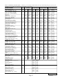
Gas-Fired Vented
Room Heater
INSTALLATION AND
OPERATING INSTRUCTIONS
R
P/N 80900 - REV. 12/03
R
NATURAL GAS VC201A VC351A
PROPANE GAS VC202A VC352A
VC501A VC701A VCR351A
VC502A VC702A VCR352A
VCR501A
VCR502A
VCR701A
VCR702A
This appliance is equipped with a safety control system designed to protect against
improper venting of combustion products.
THIS UNIT IS NOT TO BE INSTALLED IN MOBILE HOMES.
WARNING: If the information in this manual is not
followed exactly, a fire or explosion may result
causing property damage, personal injury or loss of
life.
-
Do not store or use gasoline or other flammable vapors
and liquids in the vicinity of this or any other appliance.
-
WHAT TO DO IF YOU SMELL GAS:
•
•
•
•
-
Do not try to light any appliance.
Do not touch any electrical switch; do not use any phone
in your building.
Immediately call your gas supplier from a neighbor’s
phone. Follow the gas supplier’s instructions.
If you cannot reach your gas supplier, call the fire
department.
INSTALLATION AND SERVICE MUST BE
PERFORMED BY A QUALIFIED INSTALLER,
SERVICE AGENCY OR THE GAS SUPPLIER.
RADIANT FRONT
CLOSED FRONT
The coating selected to provide longer life
to the heat exchanger may smoke slightly
upon initial firing. Provide adequate ventilation if this occurs.
WARNING: Operation of this heater when not connected to a properly installed and maintained
venting system or tampering with the vent safety shut-off system can result in Carbon Monoxide
(CO) poisoning and possible death.
This unit is not approved for installation in mobile homes, greenhouses, or environments involving
dusty, wet, corrosive, or explosive conditions. Such conditions will invalidate the warranty and may
create unsafe conditions.
TABLE OF CONTENTS
SPECIFICATIONS……………………….
INTRODUCTION………………………..
VENTING………………………………...
GAS SUPPLY…………………………….
LOCATION & SPECIAL PRECAUTIONS
COMBUSTION & VENTILATION AIR....
CLEARANCES…………………………..
DRAFT DIVERTER……………………..
DOOR KNOB……………………………
PILOT ADJUSTMENT………………….
RADIANTS & GLASS PANELS………..
8
BURNER ORIFICE & ORIFICE CHART.......... 8
PROPER BURNER FLAME.............…………. 9
MAINTENANCE…………………………....... 9
LIGHTING INSTRUCTIONS……………........ 10
TROUBLE SHOOTING CHART…………
11,12
BLOWER INSTRUCTIONS………………
13
PARTS DRAWING………………………..
14
PARTS PRICE LIST……………………….
15
WARRANTY………………………………
17
2
3
3 ,4
5
5
6
7
7
7
8
READ CAREFULLY BEFORE INSTALLING UNIT
These installation instructions are a general guide and do not supersede applicable local codes and ordinances. Before
planning or making the installation be sure it complies with all phases of the local heating code. (Or, in the absence of
local codes, with the latest edition of National Fuel Gas Code, ANSI.Z223.1, or CAN1-B149).
The appliance, when installed, must be electrically grounded in accordance with local codes, or in the absence of local
codes, with the latest edition of National Electrical Code ANSI/NFPA 70, or Canadian Electrical Code CSA-C22.1.
All of the ANSI and NFPA standards referred to in these installation instructions are the ones that were applicable at
the time the design of this appliance was certified. The ANSI standards are available from the American Gas Association,
1515 Wilson Blvd., Arlington, VA. 22209.
The NFPA standards are available from the national Fire Protection Association, 60 Batterymarch Street, Boston,
Massachusetts 02110.
Canadian standards are available from International Approval Services, 178 Rexdale Boulevard, Etobicoke, Ontario,
Canada M9W 1R3.
The design of this appliance was certified to comply with ANSI Z21.11.1 vented room heaters and CAN1-2.1-M86.
Installer must leave these instructions with the consumer, have them complete, and return the warranty card.
ROOM HEATER SPECIFICATIONS
Your room heater comes packed in a single carton. Before installation, check the rating plate to verify that the Model Number is
correct and that the room heater is equipped for the type gas you intend to use.
SPECIFICATIONS
TYPE
CONTROL
GAS
MODEL NUMBERS
CLOSED FRONT THERMOSTAT BULB NATURAL
VC201A
VC351A
VC501A
VC701A
CLOSED FRONT THERMOSTAT BULB L.P.
VC202A
VC352A
VC502A
VC702A
RADIANT FRONT THERMOSTAT BULB NATURAL
N/A
VCR351A
VCR501A
VCR701A
RADIANT FRONT THERMOSTAT BULB L.P.
N/A
VCR352A
VCR502A
VCR702A
HEIGHT
20”
26”
26”
30”
WIDTH
24”
30”
30”
36”
DEPTH
15-1/4”
15-1/4”
19-1/4”
19-1/4”
INPUT (BTU/HR.)
20,000
35,000
50,000
70,000
GAS INLET/OUTLET SIZE
1/2X3/8”
1/2X3/8”
1/2X3/8”
1/2X3/8”
VENT SIZE
3”
4”
4”
5”
CENTER OF VENT TO FLOOR
16-1/2”
21-1/2”
21-1/2”
25-1/2”
NUMBER OF RADIANTS (“VCR” SERIES)
N/A
5
5
5
NUMBER OF RADIANT GLASS (“VCR” SERIES)
N/A
2
2
2
APPROX. SHIPPING WEIGHT (“VC” SERIES)
55 LBS.
84 LBS.
112 LBS.
138 LBS.
APPROX. SHIPPING WEIGHT (“VCR” SERIES)
N/A
96 LBS.
124 LBS.
150 LBS.
*OPTIONAL BLOWER MODEL
N/A
CHB-3
CHB-3
CHB-3
*Blowers also available factory mounted on 50M Btu units. All 70M Btu units come with blower mounted only.
Page 2
INTRODUCTION
THIS IS A GAS-FIRED, GRAVITY VENTED ROOM HEATER THAT WILL OPERATE SAFELY AND PROVIDE AN EFFICIENT
SOURCE OF HEAT WHEN INSTALLED, OPERATED AND MAINTAINED AS RECOMMENDED IN THESE INSTALLATION
AND OPERATING INSTRUCTIONS. READ THESE INSTRCTIONS THOROUGHLY BEFORE INSTALLING, SERVICING, OR
USING THIS APPLIANCE. IF YOU DO NOT UNDERSTAND ANY PART OF THESE INSTRUCTIONS, CONSULT LOCAL
AUTHORITIES, OTHER QUALIFIED INSTALLERS, SERVICE AGENCIES, THE GAS SUPPLIER, OR THE MANUFACTURER.
VENTING
This heater must be connected to a properly installed and maintained venting system. This heater is equipped with a vent safety
shut-off device. Pilot outage will occur if the heater is not connected to a vent system. Pilot outage may occur due to restriction or
blockage in the vent or if connected to a masonry chimney having an area greater than the vent size shown on Page 2.
This appliance should be vented through a properly sized listed type B vent that has been constructed in accordance with the
National Building Code. If a horizontal section of vent is used, it must slope upwards a minimum of ¼ inch per foot of length.
This heater must not be connected to a vent system being used for wood or coal burning appliances. The use of more than one
appliance per vent system will most likely cause the vent safety shut-off device to shut off the heater due to the cooling of vent
temperatures through the draft diverter of the second appliance. In some situations, the vent safety shut-off may shut down the
heater if a too large, unlined, masonry chimney is used. Due to low vent temperatures associated with more efficient heaters it may
take too long to get the vent action going in a chimney before the shut-off device will shut down the heater. If this is the case, we
recommend lining the chimney with the proper size type B vent pipe or type B chimney liner.
WARNING: Do not bypass the vent safety shutoff switch. To do so could expose the consumer to
property damage, personal injury or possible death.
The switch, when activated, will extinguish the pilot flame. If the homeowner experiences this problem, the vent system must be
checked and corrected. NOTE: An existing vent that has worked for years may not be adequate for todays design because of
higher efficiency requirements resulting in lower stack temperatures. The following is a list of possible causes and corrective
actions.
POSSIBLE CAUSES
1. Blockage in vent pipe
1.A)
1.B)
CORRECTIVE ACTION
Check vent pipe for blockage, such as bird nest, wasp nest, twigs, leaves, etc.
Check that the vent cap is properly installed, not shoved too far down on the vent
pipe.
2. Burner is over firin
2.A)
2.B)
Check the manifold pressure.
Check the rate, NOTE: This appliance was orificed for elevations up to 2,000 feet.
When installed at higher elevations refer to orifice chart in main burner orifice
section of instructions for proper orifice size and re-orifice accordingly.
3. Improper vent system
A) Vent too short
3.
A)
B) Restriction in vent
system caused by
offsets
B)
Correct vent system.
The vent should not terminate less than 5 feet above the drafthood connection. A
gas vent extending through an exterior wall shall not terminate adjacent to the
wall or below eaves or parapets. Also, the top of the vent must be at least 2 foot
above any obstacles within a 10 foot radius, including the roof. See Figure A.
All type “B” vent shall extend in a generally vertical direction with offsets not
exceeding 45 degrees, except that a vent system having not more than one 60
degree offset may be allowed. Any angle greater than 45 degrees from the vertical
is considered horizontal. The total horizontal run of a vent plus the horizontal vent
connector shall be not greater than 75 percent of the vertical height of the vent.
Any offsets used should be as far above the drafthood as possible to allow a
venting action to begin before any restriction is encountered.
C)
Use listed “B” type vent pipe. Do not use transite or any other type of ceramic
pipe for venting. Do not use single wall pipe.
4.
Check the connection on both the switch and the gas valve. Tighten if necessary.
C) Incorrect vent pipe
4. Loose connections on the
vent safety wiring harness
Page 3
VENTING
More than
10’
10’ or Less
10’
2’ Min.
Ridge
3’ Min.
Ridge
Height above any
roof surface
withon 10’
horizontally
2’ Min.
3’ Min.
Chimney
Chimney
FIGURE A
FIGURE A
Termination of vent must be
securely guyed or braced if
it extends more than five (5)
feet above roof.
Seal around collar
& flashings
See
Termination
diagram
above
CONNECTING THE VENT INTO
AN EXISTING CHIMNEY
SAFE (See “Venting”)
NOTE: This may result
in the vent safety switch
shutting down the pilot
depending on size and
draw of chimney.
1/4
FIGURE 7A
Maintain
1” Clearance
Support
Laterals
UNSAFE
Firestop Support
Assembly
Terminate vent
at least 5 ft.
above draft hood
Vertical Vent
Elbow
FIGURE 7B
Listed
Appl.
RECOMMENDED
Use proper size “B”
pipe or chimney liner
inside chimney.
FIGURE 7C
Page 4
GAS SUPPLY
This vented room heater must be connected to a gas supply
capable of supplying the appliances full rated capacity.
Provide a 1/8 inch N.P.T. plugged tapping, accessible for
test gauge connection, immediately upstream of the gas
supply connection to the appliance. The minimum inlet
pressure in the gas supply pipe should be 4.5” w.c. for
Natural Gas and 11.0” w.c. for Propane Gas, “for the
purpose of input adjustment”. The maximum inlet pressure
in the gas supply pipe should never exceed 14” w.c. for
either Natural or Propane Gas. The gas supply piping
should be sized in accordance with ANSI Z223.1 National
Fuel Gas Code. The normal manifold pressure should be
3.5” w.c. for Natural Gas and 10.0” w.c. for Propane
Gas.
If the outlet pressure of the gas valve must be adjusted,
this should be done by a qualified serviceman using proper
tools and instruments.
Check all connections with soapy water for possible gas
leaks. Never use a match, candle or other ignition source.
It is recommended that pipe compound which is resistant
to the action of liquefied petroleum gases be used. Do
not use Teflon tape or Teflon impregnated compound.
The appliance and its individual shutoff valve must be
disconnected from the gas supply piping during any
pressure testing of that system at the test pressure in excess
of ½ psig.
The appliance must be isolated from the gas supply piping
by closing its individual manual shutoff valve during any
pressure testing of the gas supply piping system at test
pressures equal to or less than ½ psig.
LOCATION AND SPEICAL PRECAUTIONS
Page 5
Due to high temperatures the appliance should be
located out of traffic and away from furniture and
draperies.
Children and adults should be alerted to the hazards
of high surface temperature and should stay away
to avoid burns or clothing ignition.
Young children should be carefully supervised when
they are in the same room as the appliance.
Clothing or other flammable material should not be
placed on or near the appliance.
Any safety screen, guard, or casing top removed
for servicing a room heater must be replaced prior
to operating the appliance.
Do not use this heater if any part has been under
water. Immediately call a qualified service technician
to inspect the heater and to replace any part of the
control system and any gas control which has been
under water.
For purpose of identifying the sides of the heater.
When you are facing the front of the heater the right
side has the access door and the left side is solid.
If heater is installed in a residential garage, all burners
and pilot must be above 18”. Locate or protect
heater so it cannot be damaged by a moving vehicle.
COMBUSTION AND VENTILATION AIR
When installed, this gas appliance must be provided with fresh air for
combustion, ventilation, and dilution of hot flue gases. The minimum required
volume of the area where the appliance is installed should be 50 cubic feet per
1,000 btu/hr.
ALL COMBUSTION AIR FROM
ADJACENT INDOOR SPACES
THROUGH INDOOR COMBUSTION
AIR OPENINGS
If installed in an area of the home that is considered an unconfined space, the
natural infiltration of air around windows and doors will be adequate. If the
area is considered a confined space (less than 50 cubic feet per thousand btu),
fresh air can be supplied by providing two permanent openings into adjoining
rooms. Each opening shall have a minimum free area of one square inch per
1,000 btu per hour of the total input rating of all gas appliances in the confined
space, but not less than 100 square inches. One of the openings shall be within
12 inches of the ceiling and one within 12 inches of the floor. See Figure A.
If the home is of unusually tight construction (new and remodeled homes), free
air must be supplied through opening(s) to the outdoors. This can be
accomplished by providing 2 permanent openings, one commencing within 12
inches of the ceiling and one within 12 inches of the floor. These openings
shall communicate directly with the outdoors, or spaces that communicate
freely with the outdoors, such as a ventilated attic and crawl space through
galvanized or equivalent corrosion-resistant ducts. Exception: unobstructed
stud and joist spaces are acceptable ducts provided that not more than one fire
block is removed. Special provisions must be taken to insure that these stud
and joist spaces cannot be blocked with insulation or other objects. Each of
these openings using vertical ducts shall have a minimum free area of one
square inch per 4,000 btu/hr of total input rating of all gas appliances. See
Figure B and C. If horizontal ducts are used, the minimum free area shall be one
square inch per 2,000 btu/hr of total input rating of all gas appliances.
UL Listed Vent Cap
UL Listed Gas Vent
Opening
Opening
FIGURE A
ALL COMBUSTION AIR FROM
OUTDOORS. INLET AIR FROM
VENTILATED CRAWL SPACE AND
OUTLET AIR TO VENTILATED ATTIC
UL Listed Vent Cap
UL Listed Gas Vent
Ventilation Louvers
(each end of attic)
Fresh make-up air can also be provided through a duct to one permanent
opening commencing within 12 inches of the ceiling. The minimum free area of
this opening shall be one square inch per 3,000 btu/hr of the total input rating
of all gas appliances but not less than the sum of the areas of all vent connectors
in the space. See Figure D.
Outlet Air
Inlet Air
When calculating the amount of fresh air needed you must include make-up air
requirements for the operation of exhaust fans, kitchen ventilation systems,
clothes dryers, and fireplaces.
Additional information can be found in the latest edition of ANSI Z223.1
(National Fuel Gas Code).
Ventilation
louvers for unheated
crawl space
FIGURE B
ALL COMBUSTION AIR FROM OUTDOORS
THROUGH SINGLE COMBUSTION AIR OPENING
ALL COMBUSTION AIR FROM OUTDOORS
THROUGH VENTILATED ATTIC
UL Listed Vent Cap
UL Listed Gas Vent
UL Listed Vent Cap
UL Listed Gas Vent
Ventilation Louvers
(each end of attic)
Inlet
Grille
Inlet
Grille
FIGURE C
Opening
Outlet Air
Alternate
opening
location
Inlet Air Duct (Ends 1 Ft.
[300 mm] above floor)
Page 6
FIGURE D
CLEARANCES
DRAFT DIVERTER
If the area where the appliance is to be installed contains
carpeting, tile, or combustible materials, other than wood
flooring, the appliance shall be installed on a metal plate
(stoveboard), a wood panel, or other non-combustible
materials. The use of ceramic or quarry tile is acceptable
and provides an appealing surface that is easily cleaned.
This material is to extend 2 inches from each side and 12
inches from the front. It is advisable to extend this to the
wall behind the appliance.
The draft diverter must be installed in the same atmospheric
pressure zone as the combustion air supply for the main burner.
DOOR KNOB
Remove from the inside of the casing door and assemble to
the outside of the door. VC201 and VC202 have finger holes
in the door in lieu of knob.
Clearances to combustibles are as follows:
Ceiling
18 IN.
45.72 CM
34 IN.
86.36 CM
Projection
6 IN.
15.2 CM
20/35
From jacket to adjacent side walls, 2” on the 20/35, and
6” on the 50/70. Maintain adequate clearance on right
side for accessibility.
•
From rear surface vertical vent pipe to rear walls – 6”.
•
From rear of unit to rear wall, 13” on 20/35, and 14” on
the 50/70.
•
From top of heater to ceiling, 34” on the 20/35, and 31”
Projection
on the 50/70.
•
From top of heater to any overhanging projections such
as a mantle or window sill is 22” on the 20/35, and 19
inches on the 50/70 models, with a maximum horizontal
extension of 18 inches.
Wall
22 IN.
55.88 CM
•
13 IN.
33 CM
The clearances around the air opening into the combustion
chamber must be maintained, and the burner must be kept
clean.
Floor
CLEARANCES - VC20, VC35, VCR35
Do not permit dust or dirt to accumulate here. The other
clearances previously mentioned must be maintained.
Ceiling
18 IN.
45.72 CM
31 IN.
78.7 CM
There must be adequate room provided and maintained
around the heater for accessibility and for the flow of
combustion and ventilation air. Projection
6 IN.
15.2 CM
50/70
Wall
Projection
19 IN.
48.3 CM
14 IN.
35.6 CM
Floor
CLEARANCES - VC50 & VC70,
VCR50 & VCR70
Page 7
PILOT ADJUSTMENT
MAIN BURNER ORIFICE
The pilot flame can be observed by opening the pilot lighting
hole cover. The pilot flame should surround the top 3/8 to ½
inch of the thermocouple (see Figure 2). If the flame needs
adjusting, first locate the pilot adjustment screw cap and remove.
Adjustment screw is underneath (see Figure 1). To increase the
flame, turn the pilot adjustment screw counterclockwise
.
To decrease the flame, turn the screw clockwise
. NOTE:
The pilot is unregulated. If incoming line pressure is more than
7” w.c. Natural Gas or 11” w.c. for L.P. Gas, the pilot flame size
should be decreased.
This appliance was shipped from the factory with an orifice
sized to give the correct gas input using the gas for which the
heater was equipped. There may be local conditions, such as
variation in gas pressure or BTU content of the gas, which
may be cause for a change in the orifice. The gas company
supplying the fuel or the installing contractor should check
the gas input rate.
If the rate exceeds the “BTUH INPUT” on the rating plate by
5%, the orifice should be replaced with a smaller orifice by a
qualified technician to reduce the input to the rating plate
value.
Pilot Adj.
Screw
The input rate may need to be adjusted for elevation. See the
following charts to determine the correct orifice size for your
Model Number and elevation. These orifice sizes are based
on a heating value of 1020 for Natural Gas and 2500 for L.P.
Gas.
CAUTION: As elevation increases, derating is necessary for
the safe and proper operation of this heater. Do not increase
the Btu input rate by increasing the orifice size or gas
pressure. Allow for elevation derating when sizing gas heating
equipment.
FIGURE 1
PILOT FLAME
ADJUSTMENT
3/8 TO
1/2 INCH
NATURAL GAS
SPECIFIC ELEVATIONS
Model
0 to 2,000- 4,000 - 6,000 - 8,000’
No. 2,000’ 4,000’ 6,000’ 8,000’ 10,000’
VC201
45
47
48
49
50
VC351
35
37
38
40
42
VC501
30
31
31
32
35
VC701
25
27
28
29
30
VCR351 35
37
38
40
42
VCR501 30
31
31
32
35
VCR701 25
27
28
29
30
ORDER KIT #49820 45-1 HIGH ALTITUDE KIT
Pilot flame
should
envelop
3/8 to 1/2
inch on the
tip of the
generator.
FIGURE 2
L.P. GAS
SPECIFIC ELEVATIONS
RADIANTS AND GLASS PANELS
Model
0 to 2,0004,000 6,000 8,000’
No.
2,000’ 4,000’
6,000’
8,000’ 10,000’
VC202 1.3mm
55
56
56
57
VC352 1.65mm
53
53
54
54
VC502
47
49
49
50
51
VC702
41
42
43
44
46
VCR352 1.65mm
53
53
54
54
VCR502 47
49
49
50
51
VCR702 41
42
43
44
46
ORDER KIT #49820 45-1 HIGH ALTITUDE KIT
FOR ALL VCR MODELS
(See Figure 9 – Replacement Parts Section)
INSTALL GLASS AND RADIANTS AS FOLLOWS:
STEP 1. Remove three screws from under top of opening in
bezel frame assembly.
STEP 2. Pull top of bezel down and lay aside.
STEP 3. Remove glass from bottom pad in shipping carton.
STEP 4. Remove carton containing radiants from cavity of
combustion chamber.
STEP 5. Remove radiants from carton and install by tilting
backwards and lifting at the same time into opening. Place
the radiants on the burner radiants supports. The radiants
must be straight. Never operate heater if any radiant is
tilted to front or rear.
Continued
STEP 6. Install glass panels by inserting top edge into upper
retainer and lower into bottom support, and slide glass into
position. Do not allow a crack between the two glass panels.
Never operate heater with either glass missing or cracked.
STEP 7. Re-install bezel by placing bezel tabs over lower front
and swing bezel into position and secure with three screws.
Page 8
CAUTION: There may be momentary and spasmodic
orange flashes in the flame. This is caused by the burning
of air borne dust particles and is not to be confused with
the yellow tipping which is a stable or permanent situation
when there is insufficient primary air.
MAINTENANCE
CLEANING: To clean the front casing of your heater, it is
only necessary to use a soft cloth. Light dust can be removed
in this way. To obtain a polish or gloss, use a little light
machine oil on the cloth. Do not use metal polish or cleaning
solution. The burner ports should be kept free from lint and
dust.
CLEANING OF COMBUSTION CHAMBER
PROPER BURNER FLAME
The combustion chamber of your console heater should
never need to be cleaned if proper burner adjustment and
gas pressures are maintained. However, if an unusual
circumstance should occur, the following procedure should
be followed in cleaning your combustion chamber.
3” TO
5”
1/4”
1.
2.
INNER MANTLE
OUTER MANTLE
1/4”
3 - 5”
3.
4.
5.
6.
FIGURE 3
7.
SERVICE RECORD
8.
9.
Turn off gas supply to heater at manual valve in
supply line to heater.
Disconnect heater at ground joint union ahead of
main gas valve.
Remove main control and orifice assembly.
Remove burner.
Remove combustion chamber.
Using a scraper, scrape inside of a primary
combustion chamber. This should be area of
heaviest accumulation of carbon.
Remove plug bottom located in bottom rear of
second combustion chamber. Using a bottlebrush,
clean inside of this chamber. Shake residue out the
clean-out hole.
Clean the rear chamber by using bottlebrush
through the vent tube openings.
Replace combustion chamber, burner and control.
Check all gas piping for leaks before lighting heater.
Repair service should be performed by qualified persons.
The heater should be inspected before initial use. An annual
cleaning of control compartment and safety performance
check should be made by a qualified service person. More
frequent cleaning may be required when exposed to the
excessive lint conditions due to carpeting and bedding
material, etc. It is imperative that the control compartment,
burners, and circulating air passageways of the heater be
kept clean. Any safety screen, casing top, or guard removed
for servicing the heater must be replaced prior to operating
heater.
If the venting system is not maintained in proper operating
condition, the vent safety shutoff will not allow heater to
operate. Periodic examination of the entire venting system
as a routine part of the safety performance check is
recommended on an annual basis.
It is advised that the pilot and main burner flames be checked
at least twice during the heating season for any changes in
flame characteristics. See Figure 2 and Figure 3.
THIS IS A GAS-FIRED APPLIANCE, KEEP THE AREA CLEAR OF GASOLINE AND OTHER FLAMMABLE
VAPORS AND LIQUIDS. ALL COMBUSTIBLE MATERIAL MUST BE KEPT CLEAR OF THIS AREA.
HAVE A QUALIFIED SERVICEMAN CHECK THE BURNER PERIODICALLY. REMOVE AND CLEAN
IF NECESSARY.
Page 9
MODELS: VC201A, VC202A, VC351A, VC352A, VC501A, VC502A, VC701A,
VC702A, VCR351A, VCR352A, VCR501A, VCR502A, VCR701A, VCR702A
FOR YOUR SAFETY READ BEFORE LIGHTING
WARNING: If you do not follow these instructions exactly, a fire or explosion may result
causing property damage, personal injury or loss of life.
A. This appliance has a pilot which must be lighted by hand.
When lighting the pilot, follow these instructions exactly.
B. BEFORE LIGHTING smell all around the appliance area
for gas. Be sure to smell next to the floor because some
gas is heavier than air and will settle on the floor.
WHAT TO DO IF YOU SMELL GAS:
• Do not try to light any appliance.
• Do not touch any electric switch; do not use any phone
in your building.
• Immediately call your gas supplier from a neighbor’s
phone. Follow the gas supplier’s instructions.
•
If you cannot reach your gas supplier, call the fire department.
C. Use only your hand to push in or turn the gas control knob.
Never use tools. If the knob will not push in or turn by
hand, don’t try to repair it, call a qualified service technician.
Force or attempted repair may result in a fire or explosion.
D. Do not use this appliance if any part has been under water.
Immediately call a qualified service technician to inspect
the appliance and to replace any part of the control system
and any gas control which has been under water.
LIGHTING INSTRUCTIONS
1.
2.
3.
STOP! Read the information on the safety label.
Turn temperature control knob to “OFF” or it’s
lowest position.
Depress and turn gas control knob clockwise
to “OFF” position.
Pilot is located on
end of combustion
chamber above
burner.
Gas Control Knob
9.
NOTE: Knob can
not be turned from
“PILOT” to “OFF”
unless knob is
pushed in slightly.
Do not force.
4.
5.
6.
7.
8.
•
Wait five (5) minutes to clear out any gas. Then
smell for gas, including near the floor. If you smell
gas, STOP! Follow “B” in the information on the
safety label. If you don’t smell gas, go to the next
step.
Open casing door and pilot lighting hole cover.
Find pilot. (Follow metal pilot tube from gas control).
Locate red piezo ignitor button on top of heater.
Turn gas control knob counterclockwise
to
“PILOT”.
•
10.
11.
12.
Push in gas control knob and hold in. Immediately
begin a series of pushing and releasing the red
piezo ignitor button, while observing the pilot.
Continue to spark until pilot is lit. Continue to
hold the gas control knob in for about one (1)
minute after the pilot is lit. Release the gas control
knob and it will pop back up. Pilot should remain
lit. If pilot goes out, repeat steps 3 thru 9.
If knob does not pop up when released, STOP
and immediately call your service technician
or gas supplier.
If the pilot will not stay lit after several tries,
turn the gas control knob to “OFF” and call
your service technician or gas supplier.
Close pilot lighting hole cover and casing
door.
Turn gas control knob counterclockwise
to “ON”.
Turn temperature control knob to desired setting.
TO TURN OFF GAS TO APPLIANCE
1.
2.
Turn the temperature control knob to it’s lowest setting.
Push in gas control knob slightly and turn clockwise
to “OFF”. Do not force.
Page 10
TROUBLE SHOOTING CHART for qualified serviceman - MAIN BURNER
SYMPTOM
POSSIBLE CAUSES
Flame too large
CORRECTIVE ACTION
1. Defective operator section of gas valve.
2. Burner orifice too large.
3. Pressure regulator malfunction.
Noisy Flame
1. Noisy pilot.
Yellow tip flames (Some
yellow tipping on LP Gas
is permissible)
2.
3.
1.
2.
3.
Burr in orifice (if it whistles or resonates).
Excessive gas input.
Clogged main burner ports.
Clogged draft hood.
Linted up air shutter.
Floating Flame
Gas Odor
1.
1.
2.
3.
Blocked venting.
Chimney or flue obstruction.
Drafts around heater.
Gas leak.
Delayed Ignition
1. Pilot flame too small.
2. Burner ports clogged near pilot.
3. Low gas pressure.
4. Pilot decreases in size when main
burners come on.
5. Drafts around unit.
6. Pilot lighter door open causing
disturbance of pilot flame.
7. Improper venting.
8. Pressure regulator malfunction.
Failure to ignite
Condensation of
water vapor.
Burner won’t turn off
1. Main gas off.
2. Defective gas valve.
1. Improper venting.
1. Defective or sticking automatic valve.
2. Excessive gas pressure (The supply gas
pressure must not exceed 1/2 psi or 14”
water column).
1. Replace complete valve.
2. See orifice chart to determine the correct orifice size
for your Model Number and elevation.
3. Regulator must be adjusted by a qualified serviceman
using proper tools and instruments.
1. Reduce pilot gas with adjusting screw on combination
gas. (Fig. 1).
2. Remove burr or replace orifice (Do not enlarge orifice).
3. See “Flame Too Large”, above.
1. Clean main burner ports (Do not enlarge ports).
2. Clean draft hood.
3. Check for dust or lint at air mixer opening and around
the shutter.
1. Clean flue passageways to relieve blockage.
1. Clean flue.
2. Eliminate drafts.
3. Shut off gas service immediately. Check piping. Call
gas company. See “For Your Safety” (Page 1), and
“Gas Supply” (Page 3).
1. Check pilot orifice, clean, increase pilot gas flow if
necessary by adjusting at combination control valve
(Fig. 1).
2. Clean burner ports (do not enlarge ports).
3. Check gas supply pressure. See “Gas Supply”.
4. Supply piping is inadequately sized. Consult local gas
utility or competent installer.
5. Eliminate drafts.
6. Close pilot lighter door.
7. See “Venting” (Page 2).
8. Regulator must be adjusted by a qualified serviceman
using proper tools and instruments.
1. Open all manual gas valves.
2. Replace gas valve.
1. See “Venting”.
1. Clean or replace valve.
2. To correct this situation contact the gas company
supplying the gas. See “Gas Supply”.
TROUBLE SHOOTING CHART - POOR HEATING RESULTS
Incorrect gas input
1. Gas input not checked.
2. Clogged orifice.
3. Pressure regulator.
4. Thermostat capillary tube damaged.
Page 11
1. Re-check gas input. See “Gas Supply”.
2. Check orifices for clogging. If clogged, clean out the
hole carefully with a smooth wood toothpick. (Do not
in any way enlarge or distort it).
3. Regulator must be adjusted by a qualified serviceman
using proper tools and instruments.
4. Replace gas valve.
TROUBLE SHOOTING CHART - POOR HEATING RESULTS - Cont’d.
SYMPTOM
Not enough heat
POSSIBLE CAUSES
CORRECTIVE ACTION
1. Heater undersized.
1. This is especially true when a dwelling or room is
enlarged. Have the heat loss calculated and compare
to the heater output (70% of input). Your gas company
or installer can supply you with this information. If
heater is undersized, replace with correct size unit.
2. Raise setting of temperature dial. See “Lighting and
Shutting Down Instructions”.
3. Check gas supply pressure and regulator pressure as
outlined above.
2. Temperature dial set too low.
3. Incorrect gas supply pressure.
Too much heat
1. Temperature dial set too high.
2. Combination control valve sticks open.
1. Lower setting of temperature dial. See “Lighting and
Shutting Down Instructions”.
2. Replace combination control valve.
TROUBLE SHOOTING CHART - AUTOMATIC PILOT & VALVE
Burner won’t light
1. Pilot flame too large or too small.
2. Defective combination control valve.
Pilot outage
Pilot will not stay lit
when control knob
is released
1. Dirt in pilot orifice.
2. Pilot lighter door open.
3. Defective automatic pilot section in
combination control valve.
4. Defective thermocouple.
5. Vent safety shut off system.
1. Pilot flame too large or too small.
2. Defective thermocouple.
3. Defective gas valve.
4. Loosen connections at spill switch or
ECO on gas valve.
Page 12
1. Re-adjust pilot flame using adjustment on combination
control valves (See Fig. 1 & 1A).
2. Replace valve.
1. Clean pilot orifice with air or solvent, do not ream.
2. Close pilot lighter door.
3. Replace combination control valve.
4. Replace thermocouple.
5. See “Venting” section.
1. Re-adjust pilot flame using adjustment on combination
control valves (See Fig. 1 & 1A).
2. Replace thermocouple.
3. Replace gas valve.
4. Tighten connections.
CHB-3 BLOWER INSTALLATION
STEP 1. Run black wire and white wire that comes from bottom of junction box down through the heat shield. See Figure A.
STEP 2. Insert junction box into opening in back of heater. Attach using four #8x1/2” black screws provided. See Figure A.
STEP 3. Attach fan switch to fan switch bracket using two #8x1/2” plated, Phillip head screws provided. The 2” flange on the
bottom of bracket and terminals on the fan switch should be toward the back of the heater when properly installed.
STEP 4. Locate the two engagement holes in base of heater. On a 35,000 Btu heater these holes are approximately 6-1/2” from the
back edge and right and left holes are 5-1/4” and 7-1/4” respectfully from the right side (as viewed from back of heater). On
a 50,000 Btu heater the holes are approximately 10-3/4” from the back edge and right and left holes are 5-3/8” and 7-3/8”
respectfully from the right side. Attach fan switch bracket to base using two #8x1/2” hex head screws provided. This will
require a ¼” socket and ratchet. See Figure A.
STEP 5. Locate the blower opening and mounting tab on the base of the heater. Insert the front flange of the blower housing under
the mounting tab, lower the back of the blower down onto the base aligning the clearance holes in the blower base with the
engagement holes in the heater base. Secure the blower to the base with two #8 screws provided. See figure A.
STEP 6. Connect black wire from junction box to right fan switch terminal. See Figure B.
STEP 7. Connect white wire from junction box to white fan motor wire. See Figure B.
STEP 8. Connect black wire from fan motor to left fan switch terminal. See Figure B.
STEP 9. Turn variable speed control switch clockwise
(as viewed from front of unit) to “OFF”.
STEP 10. Plug power cord into 115 V. grounded receptacle.
STEP 11. Turn variable speed control switch counterclockwise
(as viewed from front of unit) from “OFF” to “HIGH”. Blower
will now cycle on automatically when the switch temperature is met after the main burner comes on. The blower will
continue to run for a short period after the main burner goes off. Blower speed can be adjusted by setting the variable
speed control switch between high and low.
WARNING: This appliance is equipped with a three-prong (grounding) plug for your protection against shock hazard and should
be plugged directly into a properly grounded three-prong receptacle. Do not cut or remove the grounding prong from this
plug.
CAUTION: Label all wires prior to disconnection when servicing controls. Wiring errors can cause improper and dangerous
operation. Verify proper operation after servicing.
Heat Shield
Junction
Box
FAN
SWITCH
MOTOR
BLACK
Speed
Control
WHITE
BLACK
WHITE
Power
Cord
GREEN
BLACK
Fan Switch
Bracket
MOTOR SPEED
CONTROL
Blower
Housing
“If any part of the original wire as suppied
with the appliance must be replaced, it
must be replaced with a wire of at least
a 105 degree C temperature rating.”
Mounting Tab
FIGURE B
FIGURE A
Page 13
MODELS INCLUDED:
VC / Closed Front Circulators
VCR / Radiant Front Circulators
CHB3 Blower
VENTED CONSOLE HEATER
Prices and specifications subject to
change without notice. All prices
are F.O.B. factory.
29d
35
26
38
17
36
16
29b
15
28c
23
29a
29c
28a
29e
9
34
28
10
11
33
25
19
24
28b
18
2
30
31
39
21
4
5
12
32
37
13
1
22
20
3
48
41
42
49
53
45
Mr. Contractor, we only sell parts
through our wholesalers, but the prices
listed are for your convenience. For
prompt parts service, contact the
wholesaler from which you purchased
your Cozy heater. NOTE: Parts &
schematic drawings on current models
are shown at www.cozyheaters.com.
REV. 08/01
43
46
44
50
47
51
Page 14
NOTICE: When ordering any
component in the control train
assembly, specify either
Honeywell or Robertshaw
components.
HOW TO PROPERLY ORDER PARTS: In addition to part description and part number, please give model number,and type of gas used. This
information can be found on the rating plate that is attached to rear of heater.
MODEL NUMBER
PART DESCRIPTION
Valve, 7000ASTR-4, Nat. Gas
Valve, 7000ASTR-4, L.P. Gas
Pilot Assy. 0.140.504 L.P.Gas
Pilot Assy. 0.140.514 Nat.Gas
Manifold
Orifice Nut
Burner Orifice, Natural Gas
Burner Orifice, L.P. Gas
Pilot Lighting Hole Cover
Thermocouple
Pilot Tubing Assy. w/Fittings
Vent Safety Spill Switch/ VC
Vent Safety Spill Switch/ VCR
Wiring Harness w/Bluebird
Wiring Harness w/ECO Fitting
Control Rod
Control Rod Grommet
Temperature Control Knob
Burner, Steel
Burner Mounting Plate Assy.
Casing Door
Casing Door Latch
Casing Door Knob
Casing Left Side, w/Insulation
Casing Right Side w/Insulation
Casing, Back Assembly
Casing, Top Assy. w/Insulation
“VC” Casing Front with/Insulation
“VC” Casing Trim Top & Sides
“VC” Casing Bottom Trim
“VC” Casing Center Trim w/Clips
“VCR” Bezel Assembly
“VCR” Upper Front Panel with/Insulation
“VCR” Lower Front Panel
“VCR” Casing Upper Trim
“VCR” Casing Lower Trim
Cozy Logo Emblem
Clips, for Cozy Emblem
Casing Base Assembly
Leg Levellers (4 per heater)
Heat Exchanger, Closed Front
Heat Exchanger, Radiant Front
Heat Exchanger Spacer
Rear Leg, Heat Exchanger
Draft Diverter Assembly
Gusset
Radiant Glass Panel, “VCR” Series
Radiant for “VCR” Series (5 per htr.)
Radiant Support Rail “VCR” Series
Piezo Ignitor
Piezo Wire
Valve Support Bracket
Lighting Instructions
BLOWER PARTS
Speed Control Switch w/Knob & Dec
Fan Switch
Fan Switch Bracket
Power Cord
Motor Wiring Harness
Blower/Motor Assembly
Blower Gasket - 7-1/4"
Blower Gasket - 4-5/8"
Junction Box Assembly
Junction Box Cover
Blower Nozzle Assembly
Mounting Bracket
Blower Platform Assy. (70 only)
NAT.
VC201A-R
L.P.
VC202A-R
REF. PART
LIST
NO.
1
1
2
2
3
4
5
5
9
10
11
12
12
13
13
15
16
17
18
19
20
21
22
23
24
25
26
28
28a
28b
28c
29a
29b
29c
29d
29e
N/A
N/A
30
31
32
32
N/A
32A
33
34
35
36
37
38
39
41
N/A
42
43
44
45
46
47
N/A
N/A
48
49
50
51
N/A
NO.
84090
80088
80063
80062
80110
80024
80025
80027
45332
70096
70012
80103
N/A
80190
N/A
45375
80010
80318
80123
45817
45125
80005
N/A
45102
45112
45150
45050
45070
45073
45074
45077
N/A
N/A
N/A
N/A
N/A
80006
80007
45175
80009
45200
N/A
N/A
N/A
45300
*45195
N/A
N/A
N/A
80016
80127
45860
91267
PRICE
$164.30
$164.30
$22.90
$22.90
$16.40
$2.50
$3.40
$3.40
$1.60
$11.90
$6.60
$10.60
N/A
$9.30
N/A
$5.90
$1.20
$4.40
$50.70
$12.50
$4.70
$1.20
N/A
$23.00
$24.30
$20.10
$50.20
$53.40
$19.10
$9.90
$8.00
N/A
N/A
N/A
N/A
N/A
$9.30
$2.20
$51.70
$1.50
$126.80
N/A
N/A
N/A
$35.90
$3.00
N/A
N/A
N/A
$5.70
$3.80
$5.10
$1.90
VC351,VCR351A-R VC501,VCR501A-R VC701, VCR701A-R
VC352,VCR352A-R VC502,VCR502A-R VC702, VCR702A-R
PART LIST
PART LIST
PART LIST
NO.
84090
80088
80063
80062
80111
80024
80058
80060
45332
70096
70012
80104
80100
N/A
80194
45850
80010
80318
80124
45817
45605
80005
80055
45590
45600
45615
45550
45560
45563
45564
45567
46060
46035
46040
46045
46047
80006
80007
45640
80009
45675
46100
45845
45760
45785
*45195
*80079
80073
*46160
80016
80128
45860
91267
CHB-3
70111
80253
47840
80202
80256
80251
*80257
*80258
47850
47870
47820
47835
47335
Page 15
PRICE
$164.30
$164.30
$22.90
$22.90
$16.80
$2.50
$3.40
$3.40
$1.60
$11.90
$6.60
$10.60
$10.60
N/A
$10.30
$6.20
$1.20
$4.40
$53.40
$12.50
$6.30
$1.20
$1.60
$28.70
$30.10
$40.10
$61.40
$63.80
$23.60
$12.00
$9.90
$63.80
$28.40
$25.40
$16.40
$14.90
$9.30
$2.20
$68.90
$1.50
$168.70
$174.20
$1.80
$3.80
$48.30
$3.00
$16.40
$15.20
$4.90
$5.70
$4.00
$5.10
$1.90
BLOWER
$26.70
$7.40
$3.80
$4.20
$3.80
$56.30
$1.20
$1.20
$12.70
$5.10
$13.30
$2.20
$16.40
NO.
84090
80088
80063
80062
80113
80024
80119
80120
45332
70096
70012
80104
80102
N/A
80194
45850
80010
80318
80125
45817
46445
80005
80055
46430
46440
45615
46400
45560
45563
45564
45567
46060
46035
46040
46045
46047
80006
80007
46460
80009
46500
46825
45845
45760
46560
*45195
*80079
80073
*46160
80016
80129
45860
91267
PRICE
$164.30
$164.30
$22.90
$22.90
$17.50
$2.50
$3.40
$3.40
$1.60
$11.90
$6.60
$10.60
$10.60
N/A
$10.30
$6.20
$1.20
$4.40
$53.40
$12.50
$7.20
$1.20
$1.60
$31.20
$32.70
$40.10
$67.50
$63.80
$23.60
$12.00
$9.90
$63.80
$28.40
$25.40
$16.40
$14.90
$9.30
$2.20
$76.90
$1.50
$222.70
$220.50
$1.80
$3.80
$46.00
$3.00
$16.40
$15.20
$4.90
$5.70
$4.40
$5.10
$1.90
NO.
84090
80088
80063
80062
80112
80024
80169
80167
45332
70096
70012
80099
80099
N/A
80195
47360
80010
80318
80126
45817
46445
80005
80055
47140
47150
47160
47100
47110
47113
47114
47117
47610
47585
47590
47595
47596
80006
80007
47180
80009
47200
47700
45845
45760
47295
*45195
*80079
80073
*46160
80016
80129
45860
91267
PRICE
$164.30
$164.30
$22.90
$22.90
$17.10
$2.50
$3.40
$3.40
$1.60
$11.90
$6.60
$9.60
$9.60
N/A
$10.70
$6.50
$1.20
$4.40
$57.10
$12.50
$7.20
$1.20
$1.60
$38.00
$39.40
$44.30
$74.30
$74.30
$30.90
$14.00
$12.00
$69.10
$36.40
$28.90
$19.70
$16.70
$9.30
$2.20
$83.80
$1.50
$270.20
$282.20
$1.80
$3.80
$50.10
$3.00
$16.40
$15.20
$4.90
$5.70
$4.40
$5.10
$1.90
MARCH 2005
Revised 12/03
*2 Required
IMPORTANT SAFETY BULLETIN ON YOUR GAS CONTROL AND PILOT LIGHT
SYSTEM FOR HEATING EQUIPMENT
WHAT YOU DON’T KNOW CAN HURT YOU.
Your pilot light system has been designed for safe and reliable operation. Although safety mechanisms
are built-in, the potential for hazard exists. This information is intended to help you avoid these hazards.
YOUR GAS CONTROL AND PILOT LIGHT
SYSTEM
Your gas control and pilot light system has a
safety device whose purpose is to shut-off the
gas supply to the appliance if the pilot light goes
out. If you have trouble lighting the pilot or
keeping it lit, it may mean that this safety device
is warning you that there is a problem with your
system. Inspection and repairs or replacement
must be made by a trained gas service technician.
WHAT TO DO IF YOU SMELL GAS . . .
• Do not try to light any appliance.
• Do not touch any electrical switch; do not use
any phone in your building.
• Immediately call your gas supplier from a
neighbor’s phone. Follow the gas supplier’s
instructions.
• If you cannot reach your gas supplier, call the
fire department.
Installation and service must be performed by a
qualified installer, service agency or the gas
supplier.
Do not store or use gasoline or other flammable
vapors and liquids in the vicinity of this or any other
appliance.
TAMPERING IS DANGEROUS
The pilot safety system may also not work if you
do not follow the lighting instructions carefully
or if you tamper with the gas control that you use
to light the pilot. Tampering with the gas control,
particularly with tools, can damage the safety
mechanism in the control and can allow gas to
leak. This can result in a fire or explosion causing
property damage, personal injury or death.
CRITICAL SAFETY POINTS TO REMEMBER . . .
•
•
Your gas has been odorized so that you can
smell it. Always smell around for gas before
lighting your appliance.
Sniff for L.P.-gas at floor level. LP-gas is
heavier than air and may temporarily exist at
floor level.
IF YOU SMELL GAS, DON’T LIGHT IT
•
IF YOU CAN’T LIGHT IT,
DON’T FIGHT IT!
THIS IS NOT AN ADVERTISEMENT
•
If you smell gas, do not attempt to light the
pilot. Do not cause a spark by turning on or off
electrical switches or appliances or by using the
phone. Turn off the gas to the appliances and
call your gas supplier from another location.
If your gas control has gotten wet as the result
of flooding or other wetting, it must be replaced
immediately by a trained gas service technician.
Water can lead to damage of the internal safety
mechanism in the gas control and can create a
hazardous condition.
LIMITED WARRANTY
The Louisville Tin & Stove Co. warrants to the
original user the accompanying product for the period
specified herein, provided said product is installed,
operated, maintained, serviced, and used according to the
instructions and specifications accompanying the product.
AS OUTLINED IN OUR INSTRUCTIONS, ANY
WARRANTY
CONSIDERATIONS
ARE
CONTINGENT ON INSTALLATION BY A
QUALIFIED INSTALLER (CONTRACTOR). SELFINSTALLATION IS NOT RECOMMENDED AND
MAY INVALIDATE YOUR WARRANTY.
If within a period of one year from the date of
installation of the product, any part supplied by the
manufacturer proves to be defective due to workmanship
or material, it will replace such part, provided parts have
not been subjected to misuse, alteration, neglect, or
accidents. The term of the warranty for the heat exchanger
is covered in Table A below. Any claim not made within
ten (10) days after the expiration of the warranty period
shall be deemed waived by the user.
The manufacturer shall have no liability or be
required to perform any obligation under this warranty
unless, when requested, the user returns, at the user’s
expense, the component or product claimed defective, to
the manufacturer for inspection, to enable the manufacturer
to determine if the claimed defect is covered by this
warranty.
No charges for freight, labor or other expenses
incurred in the repair, removal, or replacement of any
product or component claimed to be defective, will be
paid by the manufacturer to the user, and the
manufacturer will not be liable for any expenses
incurred, by the user, in remedying any defect in the
product.
Service under this warranty is the responsibility
of the installer. In the event service under this warranty is
needed, the user of the product shall request such service
directly from the installer. If the user is unable to locate
the installer, the user should write directly to the
manufacturer, and the name of an alternative service source
will be supplied.
The product safety registration card (packed inside
the appliance) must be completed and returned to the factory.
THIS WARRANTY IS EXPRESSLY IN LIEU
OF ANY OTHER WARRANTIES, EXPRESS OR
IMPLIED (WHETHER WRITTEN OR ORAL). ANY
IMPLIED WARRANTY OF MERCHANTABILITY OR
OF FITNESS FOR A PARTICULAR PURPOSE IS
EXPRESSLY LIMITED TO THE DURATION OF THE
MANUFACTURER’S
EXPRESS,
WRITTEN
WARRANTY.
UNDER NO CIRCUMSTANCES SHALL THE
MANUFACTURER BE LIABLE FOR ANY SPECIAL,
INDIRECT OR CONSEQUENTIAL DAMAGES OR
EXPENSES ARISING DIRECTLY OR INDIRECTLY
FROM ANY COMPONENT OR FROM THE USE
THEREOF. THE REMEDIES SET FORTH HEREIN
SHALL BE THE EXCLUSIVE REMEDIES AVAILABLE
TO THE USER AND ARE IN LIEU OF ALL OTHER
REMEDIES.
SOME STATES DO NOT ALLOW
LIMITATIONS ON HOW LONG AN IMPLIED
WARRANTY LASTS, SO THE ABOVE LIMITATIONS
MAY NOT APPLY TO YOU.
SOME STATES DO NOT ALLOW THE
EXCLUSION OR LIMITATION OF INCIDENTAL OR
CONSEQUENTIAL DAMAGES, SO THE ABOVE
LIMITATIONS OR EXCLUSIONS MAY NOT APPLY
TO YOU.
THIS WARRANTY GIVES YOU SPECIFIC
LEGAL RIGHTS, AND YOU MAY ALSO HAVE OTHER
RIGHTS, WHICH VARY, FROM STATE TO STATE.
TABLE A
Warranty for gas appliance heat exchangers only.
Product
Cozy Gas Fired Floor Furnace
Cozy Gas Fired Wall Furnace
Cozy Gas Fired Vented Console Heater
Cozy Gas Fired Direct Vent Heater
Cozy Gas Fired Counterflow Furnace
Cozy Gas Fired Counterflow Direct Vent Furnace
Cozy Gas Fired Mobile Home Direct Vent Furnace
Cozy Gas Fired Hi-Efficient Direct Vent Wall Furnace
Warranty Period
10 Years
10 Years
10 Years
10 Years
10 Years
10 Years
10 Years
10 Years
LOUISVILLE TIN AND STOVE COMPANY
P.O. Box 2767 - Louisville, Kentucky 40201-2767