1
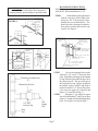
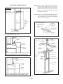
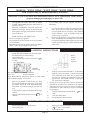
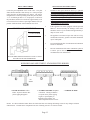
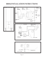
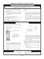
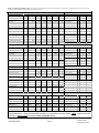
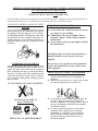
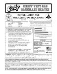
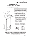
GAS-FIRED VENTED
W
ALL FURNACE
WALL
INSTALLATION AND
OPERATING INSTRUCTIONS
R
NATURAL GAS
P/N 84502
W255F, W355F, W505F
/
REV. 10/2008
L.P. GAS
R
W256F, W356F, W506F
WARNING: If the information in this manual is not
followed exactly, a fire or explosion may result causing
property damage, personal injury or loss of life.
-
Do not store or use gasoline or other flammable vapors and
liquids in the vicinity of this or any other appliance.
-
WHAT TO DO IF YOU SMELL GAS:
•
•
•
•
-
Do not try to light any appliance.
Do not touch any electrical switch; do not use any phone in
your building.
Immediately call your gas supplier from a neighbor’s phone.
Follow the gas supplier’s instructions.
If you cannot reach your gas supplier, call the fire department.
INSTALLATION AND SERVICE MUST BE
PERFORMED BY A QUALIFIED INSTALLER,
SERVICE AGENCY OR THE GAS SUPPLIER.
INSTALLER: Leave this manual with the appliance.
CONSUMER: Retain this manual for future reference.
WARNING: Operation of this furnace when not connected to a properly installed and maintained venting
system can result in Carbon Monoxide (C.O.) poisoning and possible death. For your safety, this furnace and
the venting system should be inspected at least annually by a qualified service person.
This appliance is equipped with a blocked flue switch designed to protect against a blocked flue condition.
The coating selected to provide longer life to the heat exchanger may smoke slightly upon initial firing. Please
provide adequate ventilation if this occurs.
This heater may be installed without recessing into stud space by using optional FSK (Free Standing Kit).
This unit is not approved for installation in mobile homes, greenhouses, or environments involving dusty, wet,
corrosive, or explosive conditions. Such conditions will invalidate the warranty and may create unsafe conditions.
THIS UNIT IS NOT TO BE INSTALLED IN MOBILE HOMES.
CONTENTS
Introduction................................................
Specifications..............................................
Safety Rules.................................................
Clearances....................................................
Controls........................................................
Combustion & Ventilation Air...................
Venting.........................................................
Rough-In Instructions................................
Installation....................................................
Wiring Instructions......................................
2
2
3
3
3
4, 5
6, 7
7
9
10
Lighting Instructions................................................... 11
Pilot Adjustment........................................................... 12
Burner Flame Adjustment............................................ 12
Maintenance Instructions........................................... 12
BBSK Kit Instructions...................................................13-15
WFF81 Fan Instructions.............................................. 16-17
40542 Rear Register Kit Instrucitons.......................... 18-19
Trouble Shooting Chart................................................ 20-21
Parts Drawing................................................................
22
Parts List........................................................................
23
Warranty........................................................................
25
The State of Massachusetts requires that installation and service of a gas appliance be performed by
a plumber or gas fitter licensed in the Commonwealth of Massachusetts.
READ CAREFULLY BEFORE INSTALLING UNIT
These installation instructions are a general guide, and do not supersede applicable local codes and ordinances. Before planning or
making the installation, be sure it complies with all phases of the local heating codes. Or, in the absence of local codes, with the latest
edition of the National Fuel Gas Code, ANSI.Z223.1. In Canada, see the current installation code CAN1-B149.
The appliance, when installed, must be electrically grounded in accordance with local codes or, in the absence of local codes, with the
latest edition of the National Electrical Code ANSI/NFPA No. 70. In Canada, see the current Canadian Electrical Code C5AC22.1.
The ANSI standards are available from the American Gas Association, 1515 Wilson Blvd., Arlington, Virginia 22209.
The NFPA standards are available from the National Fire Protection Association, Batterymarch Park, Quincy, MA. 02269.
Canadian standards are available from International Approval Services,178 Rexdale Blvd.,Etobicoke,Ontario, Canada M9W 1R3.
NOTE: If optional rear register kit is to be used, see supplemental installation instructions (No. 84504) and section marked “Special
Instructions for Rear Register Kit Application” prior to installation of Rough-In.
INTRODUCTION
THIS IS A GAS-FIRED, GRAVITY VENTED WALL FURNACE THAT WILL OPERATE SAFELY AND PROVIDE AN EFFICIENT
SOURCE OF HEAT WHEN INSTALLED, OPERATED AND MAINTAINED AS RECOMMENDED IN THESE INSTALLATION AND
OPERATING INSTRUCTIONS. READ THESE INSTRUCTIONS THOROUGHLY BEFORE INSTALLING, SERVICING, OR USING THE
APPLIANCE. IF YOU DO NOT UNDERSTAND ANY PART OF THESE INSTRUCTIONS, CONSULT LOCAL AUTHORITIES,
OTHER QUALIFIED INSTALLERS, SERVICE AGENCIES, THE GAS SUPPLIER OR THE MANUFACTURER.
SPECIFICATIONS
Your vented wall furnace comes packed in a single carton. (For wall thermostat models that includes the thermostat, thermostat
wire, and insulated staples). Before installing the wall furnace check the rating plate to verify that the Model Number is correct
and that the wall furnace is equipped for the type gas you intend to use.
Model
No.
Type
Control
Type
Gas
BTU/Hr. Vent
Input
Size
Gas
Inlet
W255F Wall Stat
Nat.
25,000
4”
1/2”
FINISHED DIMENSIONS
SINGLE WALL FURNACE
16-1/2”Wx68”Hx6-1/2”D
Shpg.
Wt.
REAR REG. KIT
Model
Weight
W256F Wall Stat
L.P.
25,000
4”
1/2”
W355F Wall Stat
Nat.
35,000
4”
W356F Wall Stat
L.P.
35,000
W505F Wall Stat
Nat.
W506F Wall Stat
L.P.
90 Lbs.
40542
5 Lbs.
WFF81 10 lbs.
16-1/2”Wx68”Hx6-1/2”D
90 Lbs.
40542
5 Lbs.
WFF81 10 lbs.
1/2”
16-1/2”Wx68”Hx6-1/2”D
90 Lbs.
40542
5 Lbs.
WFF81 10 lbs.
4”
1/2”
16-1/2”Wx68”Hx6-1/2”D
90 Lbs.
40542
5 Lbs.
WFF81 10 lbs.
50,000
4”
1/2”
DUAL WALL FURNACE
16-1/2”Wx68”Hx6-1/2”D
134 Lbs. N/A
N/A
WFF81 10 lbs.
50,000
4”
1/2”
16-1/2”Wx68”Hx6-1/2”D
134 Lbs. N/A
N/A
WFF81 10 lbs.
Page 2
FAN KIT
Model
Wt.
SAFETY RULES
A)
B)
C)
D)
E)
F)
G)
CONTROLS
The wall furnace should be located near the center of
the house for best heat distribution.
Due to high temperatures, the appliance should be
located out of traffic and away from furniture and
draperies.
Children and adults should be alerted to the hazards
of high surface temperature and should stay away to
avoid burns or clothing ignition.
Young children should be carefully supervised when
they are in the same room as the appliance.
Do not place clothing or other flammable material on
or near the appliance. Precautions should be taken
so as not to place furniture, drapes, or other articles
directly in front of grille or lower access door that
would obstruct air openings as proper air flow is
critical to proper operation of unit.
Any safety screen guard or casing front removed for
servicing an appliance must be replaced prior to
operating the appliance.
If the area where the appliance is to be installed
contains carpeting, tile or combustible materials, other
than wood flooring, the appliance shall be installed
on a metal plate, a wood panel or other noncombustible materials. The use of ceramic or quarry
tile is acceptable and will provide a surface that is
easily cleaned. This material is to extend the full width
and depth of the appliance.
CLEARANCES
As viewed from front of heater, the minimum clearance
from cabinet to combustible construction: Side Wall – 1”;
Floor – 2”; Ceiling – 11”.
In selecting a location for installation it is necessary
to provide adequate accessibility clearances for servicing
and proper operation. This appliance must not be connected
to a chimney flue that serves to vent a solid-fuel burning
(wood or coal) appliance, or a multi-vent system.
1”
All controls are preassembled at the factory.
The normal manifold pressure should be 3.5”
w.c. on Natural Gas and 10” w.c. on L.P. Gas. The
maximum inlet pressure in the gas supply pipe should
never exceed 14” w.c. on L.P. Gas or 7.0” w.c. on
Natural Gas.
The appliance and its individual shutoff valve
must be disconnected from the gas supply piping system
during any pressure testing of that system at test
pressures in excess of ½ psig.
The appliance must be isolated from the gas
supply piping system by closing its individual manual
shutoff valve during any pressure testing of the gas supply
piping system at test pressures equal to or less than ½
psig.
The minimum inlet pressure in the gas supply
pipe should be 5.0” w.c. on Natural Gas or 11” w.c. on
L.P. Gas, “for purpose of input adjustment”.
The appliance is orificed at the factory for
elevations up to 2,000 feet. If installed above 2,000 feet,
the BTU input must be reduced 4% per 1,000 feet. See
the following orifice chart for the proper orifice for a
specific elevation. A blank orifice is shipped in the high
altitude kit with each heater. This orifice(s) will have to
be drilled to correct size by installer, gas supplier or
qualified serviceman.
NATURAL GAS
Model
No.
0 to
2,000’
W255F
43
2,000 4,000’
44
4,000 6,000’
6,000 8,000’
8,000 –
10,000’
45
47
48
W355F
36
38
40
41
ORDER KIT #49820 45-1 HIGH ALTITUDE KIT
11”
43
W505F
43
44
45
47
48
ORDER KIT #49850 2287-2 HIGH ALTITUDE KIT
L.P. GAS
Model
No.
W256F
0 to
2,000’
1.45mm
2,000 4,000’
54
4,000 6,000’
54
6,000 8,000’
55
W356F
52
52
52
53
ORDER KIT #49820 45-1 HIGH ALTITUDE KIT
8,000 –
10,000’
55
54
W506F
1.45mm
54
54
55
55
ORDER KIT #49850 2287-2 HIGH ALTITUDE KIT
2”
Page 3
COMBUSTION AND VENTILATION AIR
When installed, this gas appliance must be provided with fresh air for combustion, ventilation, and dilution of hot
flue gases. The minimum required volume of the area where the appliance is installed should be 50 cubic feet per
1,000 btu/hr.
If installed in an area of the home that is considered an unconfined space, the natural infiltration of air around
windows and doors will be adequate. If the area is considered a confined space (less than 50 cubic feet per
1,000 btu), fresh air can be supplied by providing two permanent openings into adjoining rooms. Each opening
shall have a minimum free area of one square inch per 1,000 btu per hour of the total input rating of all gas
appliances in the confined space, but not less than 100 square inches. One of the openings shall be within 12
inches of the ceiling and one within 12 inches of the floor. See Figure A.
If the home is of unusually tight construction (new and remodeled homes), free air must be supplied through
opening(s) to the outdoors. This can be accomplished by providing 2 permanent openings, one commencing
within 12 inches of the ceiling and one within 12 inches of the floor. These openings shall communicate directly
with the outdoors, or spaces that communicate freely with the outdoors, such as a ventilated attic and crawl space
through galvanized or equivalent corrosion-resistant ducts. Exception: unobstructed stud and joist spaces are
acceptable ducts provided that not more than one fire block is removed. Special provisions must be taken to
insure that these stud and joist spaces cannot be blocked with insulation or other objects. Each of these openings
using vertical ducts shall have a minimum free area of one square inch per 4,000 btu/hr of total input rating of all
gas appliances. See Figure B and C. If horizontal ducts are used, the minimum free area shall be one square inch
per 2,000 btu/hr of total input rating of all gas appliances.
Fresh make-up air can also be provided through a duct to one permanent opening commencing within 12 inches
of the ceiling. The minimum free area of this opening shall be one square inch per 3,000 btu/hr of the total input
rating of all gas appliances but not less than the sum of the areas of all vent connectors in the space. See Figure D.
When calculating the amount of fresh air needed you must include make-up air requirements for the operation of
exhaust fans, kitchen ventilation systems, clothes dryers, and fireplaces.
Additional information can be found in the latest edition of ANSI Z223.1 (National Fuel Gas Code).
Page 4
COMBUSTION AND VENTILATION AIR
ALL COMBUSTION AIR FROM
ADJACENT INDOOR SPACES
THROUGH INDOOR COMBUSTION
AIR OPENINGS
ALL COMBUSTION AIR FROM OUTDOORS
THROUGH VENTILATED ATTIC
UL Listed Vent Cap
UL Listed Gas Vent
UL Listed Vent Cap
UL Listed Gas Vent
Ventilation Louvers
(each end of attic)
Opening
Inlet
Grille
Inlet
Grille
Opening
FIGURE A
Outlet Air
Inlet Air Duct
(Ends 1 ft. [300mm] above floor)
FIGURE C
ALL COMBUSTION AIR FROM
OUTDOORS. INLET AIR FROM
VENTILATED CRAWL SPACE AND
OUTLET AIR TO VENTILATED ATTIC.
ALL COMBUSTION AIR FROM OUTDOORS
THROUGH SINGLE COMBUSTION AIR OPENING
UL Listed Vent Cap
UL Listed Gas Vent
UL Listed Vent Cap
UL Listed Gas Vent
Ventilation Louvers
(each end of attic)
Opening
Alternate
Opening
Location
Outlet Air
Inlet Air
FIGURE D
Ventilation
louvers for unheated
crawl space
FIGURE B
Page 5
USING ADJACENT STUD SPACE
FOR ALL COMBUSTION AIR
FROM OUTSIDE
HOLES CONNECTING
TO VENTILATED ATTIC
CEILING
PLATE
AIR
GRILLE
FLOOR
PLATE
HOLES CONNECTING TO
VENTILATED CRAWL
SPACE
BASED ON 4,000 BTU OF TOTAL INPUT
RATING OF ALL GAS APPLIANCES, THE
HEATER ONLY REQUIRES A MINIMUM
FREE AREA OF:
BTU
25,000
35,000
50,000
SQUARE
IN.
6.25
8.75
12.50
HOLE
SIZE =
1”
1.5”
2”
SQUARE
IN.
.785
1.76
3.14
VENTING
This appliance must be properly connected to a venting
system.
Consult local ordinances governing venting. Install only
UL listed type BW 4” oval gas vent. When the vent enters the
attic, a listed type B-1 round flue pipe may be used. See Figure
2, Page 7.
Vent pipe must connect to the wall furnace header plate
with a “B” vent base plate and terminate with a cap at a point at
least 12 foot above the bottom of the wall furnace, two feet
above any obstacle within a 10 foot radius, and at least 3 foot
above the roof.
Provisions must be made for adequate combustion and
ventilation air.
This appliance is equipped with a manual reset blocked
flue switch designed to protect against a blocked flue condition,
which would cause combustion products to spill back into the
living quarters. NOTE: A partially blocked, inadequate, or
disconnected vent system may not activate the switch.
Discoloration of the grille is an indication of a bad vent. If this
occurs, the vent can be checked by a qualified serviceman using
a draft gauge. After 15 minutes the gauge should read between
-.02 up to -.04 inches w.c. Vent must be checked at the
beginning of each heating season.
The switch when activated on a bulb control burner will
extinguish the pilot flame, on a thermostat controlled burner, the
thermostat circuit will be broken, turning off the main burner
flame. Before the heater can be relit, the reset button must be
activated. See Figure B for location of the manual reset blocked
flue switch. To reset the switch, insert a slender rigid object
(i.e. screwdriver) through the front panel louvers and push the
reset button down. See Figure B-1. However, you may have
to remove the front panel, then reset the switch and reinstall the
front panel to relight heater. If homeowner experiences this
problem, the vent system must be checked and corrected.
NOTE: A pre-existing vent that has worked for years may not
be adequate for todays design because of higher efficiency
requirements that result in lower stack temperatures. See
“Possible Causes and Corrective Action” on Page 16.
All type “B” vents shall extend in a generally vertical
direction with offsets not exceeding 45 degrees, except that a
vent system having not more than one 60 degree offset may be
allowed.
Any angle greater than 45 degrees from the vertical is
considered horizontal. The total horizontal run of a vent plus
the horizontal vent connector shall be not greater than 75 percent
of the vertical height of the vent.
Any offsets used should be as far above the
drafthood as possible to allow a venting action to begin
before any restriction is encountered.
Page 6
ROUGH-IN INSTRUCTIONS
NOTE: Maximum wall thickness for a dual
wall (W505, W506) installation is 5-3/8”.
WARNING: Do not bypass the blocked flue
switch. To do so could expose the consumer to
property damage, personal injury or possible death.
Height above any
roof surface
within 10’
horizontally
More than 10’
FIGURE A
STEP 1.
Attach the base plate (purchased
with the vent pipe) to the header plate
using two No. 8 sheet-metal screws
through the pre-punched holes. The
heater may not vent properly without a
base plate to anchor and seal the vent
system. See Figure C.
10’
2’ Min.
Ridge
3’ Min.
10’ or Less
Chimney
2’ Min.
Ridge
3’ Min.
Installation of B-W Gas
Vent for one story buildings
or for first floor of multistory buildings
Chimney
Ceiling plate spacers to
center B-W gas vent in
stud space - nail securely
at both ends
Plate cut away for full
width of stud space to
provide ventilation
Man. Reset
Blocked
Flue Switch
Reset
Button
Draft
Diverter
Relief
Opening
Switch/
Gas
Control
Wire
Studs on 16 inch centers
Sheet metal screw base plate
to header
Use manufacturer’s method of
fastening pipe to base plate
Combustion
Chamber
FIGURE B
Header plate of vented wall furnace
(also acts as firestop)
FIGURE C
FIGURE B-1
To heater gas control valve
Manual cut-off-valve
1/8” NPT
Pressure Tap
Gas
Supply
Line
STEP 2.
Cut out an opening between the
studs of 14-3/8” x 66-1/2” above the floor
plate. Embed the rear flange of the channel
on top of header into either the drywall or
the plastered wall. This provides part of
the required fire stop. Square up and nail
the header in place with the top front of
header located 65-3/4” above floor plate.
(See arrow on right side of header and
Figure 1, 5A and 5B on Page 7).
STEP 3.
Rough in ½” gas supply on center
line of left stud either 4” above top of floor
plate or 4” to right of left stud through floor
plate. See Figure 1 located on Page 7.
Drip
Leg
GAS SUPPLY
Page 7
STEP 4.Remove double ceiling plate between studs.
Install one ceiling plate spacer across the cut out
in ceiling plate. Install vent pipe into position,
be sure to lock bottom of vent pipe into the base
plate. Nail second ceiling plate spacer in place.
(See Figure C, Page 6).
ROUGH-IN INSTRUCTIONS
FIGURE 1
ROUGH-IN
DIMENSIONS
STEP 5.If the vent continues through additional stories
within the 2x4-stud space, then fire-stop-spacers
must be installed at the second and subsequent
ceiling levels. See Figure D.
*65-3/4”
* This
measurement
must be
taken from
top of
floor
plate
14-1/4”
Min.
14-1/2” Max.
Installation of B-W gas
vent for each subsequent
ceiling or floor level
of multi-story
buildings
4”
Firestop spacers
supplied by
manufacturer of
B-W gas vent
Plate cut away to
provide passage of
B-W gas vent
4”
Nail firestop
spacer securely
NOTE: For proper combustion, make sure units are
level, front to back and side to side.
FIGURE D
Dry-Wall
B-W Type Vent
Screw
VENT INSTALLATION
LISTED
VENT TOP
2 FT. MIN.
STORM COLLAR
ROOF
FLASHING
Front
Panel
Plaster
Ground
CEILING PLATE
SPACERS
NOTE: Front Panel must be in front of plaster ground
channel. Do not hang it over front of plaster ground.
FIGURE 5A - DRY WALL
OVAL TO
ROUND ADAPTER
LISTED “BW”
VENT PIPE
12 FT.
MIN.
Plaster
B-W Type Vent
Screw
CEILING
PLATE
SPACER
LANCES
BASE PLATE
HEADER PLATE
2 X 4 WALL
STUDS
Front
Panel
Plaster
Ground
NOTE: Front Panel must be in front of plaster ground
channel. Do not hang it over front of plaster ground.
FIGURE 2 - VENT INSTALLATION
FIGURE 5B - PLASTER WALL
Page 8
INSTALLATION
B-W VENT
STEP 6.
To place furnace into position, grasp
furnace and lift so furnace flue vent and header
plate vent opening engage. Do not use burner or
gas control to lift heater. Lift furnace upward and
swing bottom into wall opening until legs rest on
floor plate and are flush to finished wall. For proper
combustion, level heater front to back and side to
side. Nail legs to studs. DO NOT BEND LEGS
as this will put the entire unit into a bind and cause
expansion noises (See Figure 3).
STEP 7.
A drip leg and a manual valve equipped
with a 1/8 N.P.T. plugged tapping accessible for
test gauge connection should be installed
immediately upstream of the gas supply connection
to the appliance. Some codes and ordinances
require that the manual valve be located outside
the appliance.
FIGURE 3
STEP 8.
Make gas connection using connector the
same size as gas connection of furnace. CHECK
ALL CONNECTIONS FOR GAS LEAKS
WITH LEAK DETECTOR SOLUTION. DO
NOT USE OPEN FLAME.
STEP 9.
For wall thermostat units, see “Wiring”
section for thermostat connections. Make sure
all connections are correct and connector stems
are not touching.
BURNER
SHELF
FIGURE 4
Casing
“Z Bracket
Front Panel
Front
Panel
Door
STEP 10.
To fasten front panel to furnace, be sure
exposed portion of header is free of debris. Place
outer panel over furnace with top of panel about
one inch above header and centered in opening.
Keep front panel flush to finished wall and slide
down until rear flange of top outer panel is wedged
tight against the front of the plaster ground channel
and flush with wall. CAUTION: Do not hang
front panel behind (over front lip) the plaster
ground channel as this could result in
excessive noise. Open bottom door of front
panel and place sheet metal screw into locking
latch. Secure top of front panel to header plate
with screw provided. This will hold front panel
securely to wall. See Figures 5A, 5B, (See Page
8), and 5C (Page 9).
FIGURE 5C
Page 9
CAUTION: Label all wires prior to disconnection when
servicing controls. Wiring errors can cause improper
and dangerous operation. Verify proper operation
after servicing.
Thermostat
Manual
Reset
Blocked
Flue Switch
WIRING INSTRUCTIONS –
GRAVITY WALL FURNACE
WARNING: Failure to locate the thermostat properly
or to wire the furnace correctly may result in continuous
operation, control damage or failure to operate. This can
cause property damage, personal injury, or loss of life.
Follow the instructions included with the thermostat. Locate
the thermostat approximately five (5) feet above the floor
and four feet (4’) from appliance. Always mount the
thermostat on an inside wall where it won’t be affected by
heat or cold sources such as direct sunlight, televisions,
fireplaces, hidden hot or cold water pipes, drafts, etc. The
thermostat must never be installed in an adjoining room where
a door can be closed between the thermostat and wall
furnace. This wall furnace is equipped with a self generating
control system. Never connect to a 24 volt transformer or
to the household electrical system. Do not use more
thermostat wire than is included with the wall furnace. Do
not run thermostat wire in same stud space with vent.
Conceal wire inside wall or secure to wall with insulated
staples that are included .
YOUR FURNACE IS SHIPPED WITH A WALL
THERMOSTAT (Figure 8). YOU MAY CONVERT
CONTROL TO BUILT-IN BULB CONTROL WITH
THE OPTIONAL BBSK KIT. SEE PAGE 13, 14 and 15
FOR INSTALLATION INSTRUCTIONS.
Page 10
WALL
THERMOSTAT
MODELS
NAT.
L.P.
W255F W256F
W355F W356F
W505F W506F
FIGURE 8
Pilot
Generator
Wire
Nut
Gas Valve
LIGHTING INSTRUCTIONS
MODELS: W255F, W256F / W355F, W356F / W505F, W506F
FOR YOUR SAFETY READ BEFORE LIGHTING
WARNING: If you do not follow these instructions exactly, a fire or explosion may result causing
property damage, personal injury or loss of life.
A.
B.
•
•
•
•
This appliance has a pilot which must be lighted
by hand. When lighting the pilot, follow these instructions exactly.
BEFORE LIGHTING smell all around the
appliance area for gas. Be sure to smell next to the
floor because some gas is heavier than air and will
settle on the floor.
C.
WHAT TO DO IF YOU SMELL GAS:
Do not try to light any appliance.
Do not touch any electric switch; do not use any phone
in your building.
Immediately call your gas supplier from a neighbor’s
phone. Follow the gas supplier’s instructions.
D.
If you cannot reach your gas supplier, call the fire
department.
Use only your hand to push in or turn the gas control
knob. Never use tools. If the knob will not push in
or turn by hand, don’t try to repair it, call a qualified
service technician. Force or attempted repair may
result in a fire or explosion.
Do not use this appliance if any part has been under
water. Immediately call a qualified service technician
to inspect the appliance and to replace any part of the
control system and any gas control which has been
under water.
LIGHTING INSTRUCTIONS
1.
2.
3.
4.
STOP! Read the information on the safety label.
Set thermostat to it’s lowest setting.
Open cabinet door.
Depress and turn gas control knob clockwise
to “OFF”.
Gas Control Knob
Pilot is
located
on side
of burner
Manifold
Pressure Tap
Pilot Adjustment
Screw Cap
Internal Manifold
Pressure Regulator
NOTE: Knob cannot be turned from “PILOT” to “OFF” unless
knob is pushed in slightly. Do not force.
5.
6.
7.
Wait five (5) minutes to clear out any gas. Then
smell for gas, including near the floor. If you smell
gas, STOP! Follow “B” in the information on the
safety label. If you don’t smell gas, go to the next
step.
Locate the pilot. (Follow metal pilot tube from gas
control).
Turn gas control knob counterclockwise
to
“PILOT”.
8.
Push gas control knob and hold in. Immediately
light the pilot with a match. Continue to hold the
gas control knob in for about one (1) minute after
the pilot is lit. Release gas control knob and it will
pop back up. Pilot should remain lit. If pilot goes
out, repeat steps 4 through 8.
• If knob does not pop up when released, STOP and
immediately call your service technician or gas supplier.
• If the pilot will not stay lit after several tries, turn the gas
control knob to “OFF” and call your service technician
or gas supplier.
9.
Turn gas control knob counterclockwise
to
“ON”.
10.
Close the cabinet door.
11.
Set thermostat to desired setting.
TO TURN OFF GAS TO APPLIANCE
1.
2.
Set the thermostat to it’s lowest setting.
Open cabinet door.
3.
4.
Page 11
Push in gas control knob slightly and turn clockwise
to “OFF”. Do not force.
Close cabinet door.
PILOT ADJUSTMENT
MAINTENANCE INSTRUCTIONS
Locate the pilot adjustment screw on the valve. The pilot
flame should surround at least the top 3/8” of the powerpile
(pilot generator) or thermocouple (see below). The pilot is
unregulated so it will be operating at inlet line pressure (Max.
7” w.c. for natural gas and 11” w.c. for propane). To decrease
the pilot flame, turn the screw clockwise (approximately seven
to nine full turns to bottom of pilot light channel) until you
produce sufficient flame at the minimum noise level.
1.
Installation and repair should be done by a qualified
service person. The appliance should be inspected before
use and at least annually by a professional service person.
More frequent cleaning may be required due to excessive
lint from carpeting, bedding material, etc. It is
imperative that control compartments, burners, pilot
burners, circulating air passageways and venting systems
of the appliance be kept clean.
2.
If the appliance has been equipped with the optional
WFF81-C fan kit assembly, the bearings of the motor
should be oiled every six months with approximately 2
drops of S.A.E. 20 oil.
3.
The appliance area must be kept clear and free of any
combustible materials, gasoline and other flammable
vapors and liquids.
4.
It is essential that the flow of combustion and ventilation
air not be obstructed.
5.
Periodic examination of the entire ventilation system as
a routine part of the safety performance check is
recommended on an annual basis.
PILOT FLAME ADJUSTMENT
3/8 TO 1/2 INCH
PILOT FLAME SHOULD ENVELOP 3/8 TO 1/2 INCH
OF THE TIP OF THE GENERATOR.
BURNER FLAME ADJUSTMENT - STAINLESS STEEL BURNER
1
Air
Shutter
1. FLAME TOO SOFT - Yellow
Flame. Open air shutters until
yellow tipping disappears.
2
3
2. FLAME TOO HARD - Deep Blue
Coloration. Closing air shutters
to a point where yellow tipping
begins, re-open slightly to
eliminate yellow tipping. Air
shutter adjustment is now correct.
3. NORMAL FLAMES
NOTE: It is advised that the burner flames be checked at least twice during the heating season for any changes in burner
characteristics. Vacuum burner compartment at start of heating season or as often as needed.
Page 12
BBSK INSTALLATION INSTRUCTIONS
STEP 1.
Select left or right side of front panel for most convenient location of the temperature control knob. Remember
to choose the side that allows adequate clearance for accessibility to adjust the control knob.
STEP 2.
On selected side, locate three (3) vertical dimples beginning approximately 20-½” above bottom of the front
panel. See Figure 9.
*On Gravity Wall Furnaces manufactured prior to November 2005 (without bracket hole dimples in the left
and right side), you may use the gravity BBSK bracket as a template to locate holes. Measure 20-1/2” up on
the preferred side, to locate lowest hole.
STEP 3.
Using these three (3) dimples as locator, drill three ¼” holes.
STEP 4.
Remove the BBSK control switch from the packing set. See Figure 10.
STEP 5.
Secure P/N 40225 switch bracket to the BBSK control switch using two (2) #6x¼” screws provided. See Figure
10.
STEP 6.
Place BBSK control switch inside front panel, align engagement holes with clearance holes in P/N 40230 heat
shield and the ¼” drilled holes in the front panel. Attach using two (2) #8x½” screws provided. Make sure
heat shield is between the BBSK control switch and the heat exchanger.
STEP 7.
Connect each end of the black wires to the two outside terminals on the BBSK control switch, route wires
down the inside of the front panel. See Figure 11.
STEP 8.
Straighten the bulb capillary tube using extreme care not to bend or damage the tube, route the tube down the
inside of the front panel.
STEP 9.
Install the front panel onto the wall furnace.
STEP 10.
Insert the control knob onto the control rod. See Figure 10.
STEP 11.
Open the front panel door.
STEP 12.
Connect one black wire to the stripped end of the blue blocked flue switch wire. Connect the other black wire
to the “TH/TP” terminal on the gas valve. See Figure 11. NOTE: If you are replacing an existing wall
thermostat, you must first disconnect the thermostat wires from the gas valve.
STEP 13.
Secure the sensing bulb to the bottom of the gas valve using the nylon clamp and blunt screw provided. See
Figure 12.
STEP 14.
Close the front panel door.
STEP 15.
Follow the lighting instructions to place the heater in operation.
Page 13
BBSK INSTALLATION INSTRUCTIONS
SIDE VIEWS / FRONT PANEL
40225
SWITCH
BRACKET
BBSK
CONTROL
SWITCH
40230
HEAT
SHIELD
FRONT
PANEL SIDE
#6X1/4 (2)
SCREW
SENSING
BULB
CONTROL
KNOB
CAPILLARY
TUBE
CONTROL ROD
#8X1/2 (2)
SCREW
FIGURE 10
GAS VALVE
20-1/2”
BBSK CONTROL
SWITCH
RIGHT
SIDE
VIEW
LEFT
SIDE
VIEW
FIGURE 9
Blue Wire
Blocked
Flue Switch
Blue Wire
BLACK WIRE
FIGURE 11
GAS VALVE
NYLON CLIP
SENSING BULB
10-24X3/8 SCREW
FIGURE 12
Page 14
BBSK KIT LIGHTING INSTRUCTIONS
FOR YOUR SAFETY READ BEFORE LIGHTING
WARNING: If you do not follow these instructions exactly, a fire or explosion may result causing
property damage, personal injury or loss of life.
A.
B.
•
•
•
This appliance has a pilot which must be lighted by
hand. When lighting the pilot, follow these instructions exactly.
BEFORE LIGHTING smell all around the
appliance area for gas. Be sure to smell next to the
floor because some gas is heavier than air and will
settle on the floor.
WHAT TO DO IF YOU SMELL GAS:
Do not try to light any appliance.
Do not touch any electric switch; do not use any phone
in your building.
Immediately call your gas supplier from a neighbor’s
phone. Follow the gas supplier’s instructions.
•
C.
D.
If you cannot reach your gas supplier, call the fire
department.
Use only your hand to push in or turn the gas control
knob. Never use tools. If the knob will not push in
or turn by hand, don’t try to repair it, call a qualified
service technician. Force or attempted repair may
result in a fire or explosion.
Do not use this appliance if any part has been under
water. Immediately call a qualified service technician
to inspect the appliance and to replace any part of the
control system and any gas control which has been
under water.
LIGHTING INSTRUCTIONS
1.
2.
3.
4.
STOP! Read the information on the safety label.
Turn temperature control knob clockwise
to
“LO”.
Open cabinet door.
Depress and turn gas control knob clockwise
to “OFF”.
Pilot is
located
on side
of burner
GAS CONTROL KNOB
NOTE: Knob cannot be
turned from “PILOT” to
“OFF” unless knob is
pushed in slightly. Do
not force.
5.
6.
7.
8.
Wait five (5) minutes to clear out any gas. Then
smell for gas, including near the floor. If you smell
gas, STOP! Follow “B” in the information on the
safety label. If you don’t smell gas, go to the next
step.
Locate the pilot. (Follow metal pilot tube from gas
control).
Turn gas control knob counterclockwise
to
“PILOT”.
Depress gas control knob and hold in. Immediately
light the pilot with a match. Continue to hold the gas
control knob in for about one (1) minute after the
pilot is lit. Release gas control knob and it will pop
back up. Pilot should remain lit. If pilot goes out,
repeat steps 4 through 8.
• If knob does not pop up when released, STOP and
immediately call your service technician or gas supplier.
• If the pilot will not stay lit after several tries, turn the gas
control knob to “OFF” and call your service technician
or gas supplier.
9.
Turn gas control knob counterclockwise
to
“ON”.
10.
Close the cabinet door.
11.
Turn temperature control knob to desired setting.
TO TURN OFF GAS TO APPLIANCE
1.
2.
Turn temperature control knob clockwise
“LO”.
Open cabinet door.
to
3.
4.
Page 15
Push in gas control knob slightly and turn clockwise
to “OFF”. Do not force.
Close cabinet door.
P/N 91288 09/05
MODEL WFF81-C OPTIONAL FAN KIT
INSTALLATION INSTRUCTIONS
NOTE: This fan kit is to be installed after installation of wall furnace and with the wall furnace front panel in
place.
STEP 1.
This appliance, when installed, must be electrically grounded in accordance with local codes, or in
the absence of local codes, with the latest edition of the National Electric Code, ANSI/NFPA
No. 70. In Canada, see the current Canadian Electrical Code CSA C22.1.
STEP 2.
Set fan kit on top of the wall furnace front panel. Using the back top edge of the fan kit cabinet
as a guide, mark a horizontal line across the wall. Mark a small vertical line which aligns with the
slotlocatedtowardtherearofthefankitcasing.
STEP 3.
Using the four one inch screws provided, secure the wall mounting bracket to wall 1/8” below the
horizontal line. Fan attachment bracket must be up and threaded nut sert aligned with the small
vertical line. Note: Anchors (not provided) may be required.
STEP 4.
Remove junction box and connect 115v power supply in accordance with the wiring diagram.
Replace junction box.
STEP 5.
Set fan kit on top of wall furnace front panel. Slot should align with the nut sert. Secure fan kit
to wall mounting bracket with thumb screw provided.
Thumb
Screw
Threaded Nut
Sert
Slot
Wiring
Diagram
Fan Attachment
Bracket
Wall Mounting
Bracket
One Inch
Screw (4)
Junction
Box
Fan
Kit
Wall Furnace
Front Panel
Page 16
WFF81-C WIRING SCHEMATIC
Ground
L2 White
115 VAC
L1 Black
115 VAC
WHITE
BLACK
BLACK
WHITE MOTOR
BLACK
BLACK
FAN SWITCH
BLACK
GREEN GROUND WIRE
L2
White
115 VAC 60 HZ - Less than 12 Amps. If any of the original wire as
supplied with this appliance must be replaced, it must be replaced with
type thermoplastic 105 degree C wire or its equivalent.
Page 17
L1
Black
40542-A REAR REGISTER KIT (Optional Accessory)
INSTALLATION INSTRUCTIONS FOR GRAVITY VENTED WALL FURNACES
STEP 1.
Cut hole within stud space behind heater in the back wall 8-1/4” high by 12-5/8” wide. The lower
edge of the hole to be 45-3/4” above the floor plate or 47” from the floor (with standard 2”x4”
floor base) as shown in Figure 13.
STEP 2.
Install plaster ground frame for rear register in hole and nail frame to stud as shown in Figure 14.
STEP 3.
REAR REGISTER INSTALLATION: Cut and remove embossed plates in inner and outer casing.
Follow instructions for installation of regular furnace.
STEP 4.
After furnace is installed, attach rear register grille as shown in Figures 16 & 17 by insertion over
plaster ground and attach with sheet metal screws, provided.
STEP 5.
Damper as shown in Figure 17 can be adjusted from full open for maximum heat to fully closed.
14-3/8”
12-5/8”
PLASTER
PLASTER
8-1/4”
HOLE FOR
BACK
REGISTER
NAIL TO
STUD
STUD
OPENING 7/8”
FROM EACH
STUD
STUD
STUD
PLASTER
45-3/4”
PLASTER
STUD
PLASTER
PLASTER
PLATE
PLATE
PLACING FRAME FOR REAR REGISTER
FIGURE 14
ROUGH-IN DIMENSIONS FOR REAR REGISTER
FIGURE 13
40542-A REAR REGISTER KIT
(Used on Single Wall models only)
40542 REAR REGISTER KIT
(W25/35 Series only)
Part Description
Damper
Damper Spring
Frame Assembly
Register Chain
Bell, Pull
Register Assembly
Installation Instructions
Page 18
Ref.
No.
22
23
24
25
26
27
--
Part
No.
40375
40377
40365
40379
85003
40355
84504
Form #84504
REV. 07/98
40542-A REAR REGISTER KIT - Continued
INSTALLATION INSTRUCTIONS FOR GRAVITY VENTED WALL FURNACES
INNER PANEL
Plaster
Ground
Frame
Damper
Open Position
Closed
Position
Casing
Finished Wall
2”x4” Upright
Rear
Register
Grille
FIGURE 15
FIGURE 17
Casing
Opening
Heater
Casing
Finished
Wall
Retainer
Screw
Holes
Rear
Register
Grille
Plaster Ground
Frame
Form #84504
REV. 07/98
Page 19
FIGURE 16
TROUBLE SHOOTING CHART for qualified serviceman - MAIN BURNER
SYMPTOM
POSSIBLE CAUSES
Flame too large
1. Defective operator section of gas valve.
2. Burner orifice too large.
Flame pops back
Noisy Flame
Yellow tip flame
(some yellow tipping
on L.P. gas is
permissible)
CORRECTIVE ACTION
3.
1.
1.
2.
If installed above 2,000 ft.
Too much primary air.
Too much primary air.
Noisy pilot.
3.
4.
1.
2.
3.
4.
Burr in orifice (if it whistles or resonates).
Excessibe gas input.
Too little primary air.
Clogged main burner ports.
Clogged draft hood.
Linted up air shutter.
Floating Flame
1. Blocked venting.
2. Insufficient primary air.
Gas Odor
1. Gas leak.
Delayed Ignition
2. Chimney or flue obstruction.
3. Drafts around appliance.
1. Pilot flame too small.
2. Burner ports clogged near pilot.
3. Low gas pressure.
4. Pilot decreases in size when main burners
come on.
5. Air shutter open too far.
Failure to Ignite
Condensation of
water vapor
Burner won’t
turn off
Incorrect gas input
6.
7.
1.
2.
1.
Drafts around appliance.
Bad venting.
Main gas off.
Defective gas valve.
Improper venting.
1. Defective or sticking automatic valve.
2. Excessive gas pressure (The supply gas
pressure must not exceed 1/2 psi or 14”
water column).
1. Gas input not checked.
2. Clogged orifice.
Not enough heat
1. Appliance undersized.
Too much heat
2. Temperature dial set too low. (Bulb
type valves).
3. Incorrect supply pressure.
1. Temperature dial set too high.
2. Combination control valve sticks open.
Page 20
1. Replace complete valve.
2. Check with local gas company for proper
orifice size and replace.
3. Refer to orifice chart, Page 3.
1. Adjust air shutter. (See Page 12).
1. Adjust air shutter. (See Page 12).
2. Reduce pilot gas with adjusting screw on
combination gas control valve.
3. Remove burr or replace orifice (Do not enlarge orifices).
4. See “Flame Too Large” above.
1. Adjust air shutter. (See Page 12).
2. Clean main burner ports. (Do not enlarge ports).
3. Clean draft hood.
4. Check for dust or lint at air mixer opening and
around the shutter. Clean as necessary.
1. Clean flue passageways to remove blockage.
2. Adjust air shutter to increase primary air supply.
(See Page 12).
1. Shut off gas service immediately. Check
piping. Call gas company. (See Page 1).
2. Clean flue.
3. Eliminate drafts.
1. Check pilot orifice, increase pilot gas flow
if necessary by adjusting inlet pressure.
2. Clean burner ports (Do not enlarge ports).
3. Check gas supply pressure.
4. Supply piping is inadequately sized. Consult local
gas utility or competent installer.
5. Close air shutter to proper setting as outlined in these
instructions (slight yellow tipping is allowable on
L.P. Gas). (See Page 12).
6. Eliminate drafts.
7. See “Venting”.
1. Open all manual gas valves.
2. Replace gas valve.
1. See “Venting”.
1. Clean or replace valve.
2. To correct this situation contact the utility
supplying the gas.
1. Re-check gas input.
2. Check orifice for clogging. If clogged,
clean out the hole carefully with a smooth wood toothpick.
(Do not in any way enlarge or distort it).
1. This is especially true when a dwelling or room is
enlarged. Have the heat loss calculated and compare
to the appliance output (70% of input). Your gas
company or installer can supply you with this
information. If appliance is undersized, replace with
correct size unit.
2. Raise setting of Temperature Dial. See
“Lighting and Shutting Down Instructions”.
3. Check supply pressure as outlined above.
1. Lower setting of temperature dial. See “Lighting
and Shutting Down Instructions”.
2. Replace combination control valve.
TROUBLE SHOOTING CHART - AUTOMATIC PILOT & VALVE
SYMPTOM
POSSIBLE CAUSES
CORRECTIVE ACTION
Burner won’t
turn on
1. Pilot flame too large or too small.
1. Re-adjust pilot flame using adjustment on
combination control valve.
2. Clean pilot orifice with air or solvent, do
not ream.
3. Replace entire combination control valve.
2. Dirt in pilot orifice.
3. Defective automatic pilot section in
combination control valve.
4. Defective pilot generator.
5. Defective combination control valve.
6. Manual reset blocked flue switch
tripped.
4. Replace pilot generator.
5. Replace valve.
6. Reset switch, see Page 6 and blocked flue
section below.
TROUBLE SHOOTING CHART - BLOCKED FLUE SWITCH (FOR USE BY A QUALIFIED SERVICEMAN)
POSSIBLE CAUSES
1. Blockage in
vent pipe
2. Burner is
overfiring
3. Improper vent
system
A. Vent too short
B. Restriction in
vent system
caused by offsets
C. Incorrect vent pipe
4. Incorrect header
plate location
5. Vent pipe not down
on the header plate
securely
6. Loose connections
on the vent safety
wiring harness
CORRECTIVE ACTION
A. Check vent pipe for blockage, such as bird nest, wasp nest, twigs, leaves, etc.
B. Check inside the bottom of the vent pipe to make sure the top of the draft diverter did not
rip the inner liner causing it to block part of the vent opening.
C. Check that no insulation from the header plate got caught on top of the draft diverter when
the heater was inserted into the wall.
D. Check that the vent cap is properly installed, not shoved too far down on the vent pipe.
A. Check the manifold pressure.
B. Check the rate, NOTE: This appliance was orificed for elevations up to 2,000 feet. When
installed at higher elevations refer to orifice chart in controls section of instructions for
proper orifice size and re-orifice accordingly.
3. Correct vent system.
A. The vent should terminate a minimum of 12 feet above the floor. See Figure 2. Also, the
top of the vent must be at least 2 foot above any obstacle within a 10 foot radius, including
the roof. See Figure A.
B. All type “B” vents shall extend in a generally vertical direction with offsets not exceeding 45
degrees, except that a vent system having not more than one 60 degree offset may be allowed.
Any angle greater than 45 degrees from the vertical is considered horizontal. The total
horizontal run of a vent plus the horizontal vent connector shall be not greater than 75 percent
of the vertical height of the vent.
Any offsets used should be as far above the drafthood as possible to allow a venting action to
begin before any restriction is encountered.
C. Use listed BW type vent pipe. Do not use tansite or any other type of ceramic pipe for venting.
Do not use single wall pipe. When venting into a masonry chimney the chimney must be
properly lined and sized for this gas furnace. The use of type B or flexible chimney liner is
recommended.
4. The header plate must be 65-3/4” above the floor plate. See rough-in instructions.
5. Use a base plate (obtained from the vent pipe manufacturer) on top of our header plate.
This will lock the vent pipe down and prevent the draft diverter from shoving it up.
6. Check the connection on both the switch and the gas valve. Tighten if necessary.
DO NOT BYPASS THE BLOCKED FLUE SWITCH
To do so could expose the consumer to property damage, personal injury or possible death.
Page 21
Prices and specifications subject
to change without notice. All
prices are F.O.B. factory.
SINGLE WALLFURNACE
Model Numbers
Nat.
L.P.
GRAVITY WALL FURNACE
LIST PRICES - - MARCH 2009
DUALWALLFURNACE
Model Numbers
Nat.
L.P.
12
W255F W256F
1
12
7
W505F W506F
10
7
W355F W356F
1
10
9
7A
47
1
46
4
9
46
11
47
9
2
4
8
8
11
3
8
11
2
3
2
38
29
13
49
44
48
19
36
32
30
31
14
29A
43
15
35
29
28
20 21
17
16
38
44
18
WFF81-C FAN KIT Used on
Single and Dual Wall models
35
36
32
39
57
58
BURNER ASSEMBLY /
SINGLE WALL FURNACE
33
39
27
25
26
24
22
23
REAR REGISTER KIT - Used
on Single Wall models only
59
60
BURNER ASSEMBLY /
DUAL WALL FURNACE
56
40
FSK-A
55
THERMOSTAT
FREE STANDING
KIT
NOTICE: When ordering any component in the Burner Assembly,
specify either Honeywell or Robertshaw components.
REV. 06/2006
Page 22
HOW TO PROPERLY ORDER PARTS: In addition to part description and part number, please give model number, serial number, and type of gas used. This
information can be found on the rating plate that is attached to heater.
F R O N T P A N E L, D O O R & B O D Y A S S E M B LY
W2 5 F
F O R M O D E LS
P ART DESCRIP TION
WF F 8 1- C F A N KIT
W3 5 F
W5 0 F
(Fits all M o dels)
REF.
P A RT
LIST
P ART
LIST
P A RT
LIST
NO.
NO.
P RICE
NO.
P RICE
NO.
P RICE
P A RT DESCRIP TION
REF.
P A RT
LIST
NO.
NO.
PRICE
Fro nt P anel Assembly
1
40025 $ 142.40
40025 $ 142.40
*40025 $ 142.40
Fan Cabinet
13
40304 $ 39.00
Lo wer Do o r
2
40032 $
11.20
40032 $
11.20
*40032 $
11.20
Junctio n B o x
14
40315 $
8.00
Handle Assembly
3
40033 $
5.10
40033 $
5.10
*40033 $
5.10
M o to r M o unting B rk.
15
40313 $
4.80
B o dy A ssembly
4
39805 $ 184.10
39805 $ 184.10
40103 $ 212.30
M o to r
16
85110 $ 65.70
Draft Diverter A ssembly
7
40042 $ 43.60
40045 $
43.50
40141 $ 40.00
Fan B lade
17
85115 $
Draft Diverter A ssembly
7A
N/A
40140 $ 40.60
Heyco Strain Relief
18
84155 $
1.40
Fan Switch
19
84170 $
6.60
Wiring Diagram (label)
20
91147 $
1.40
Fan Ho using
21
40311 $ 20.90
Heat Exchanger
N/A
N/A
8
40260 $
151.10
Upper Shield
9
40068 $
Header A ssembly
10
N/A
40265 $ 148.60
*40260 $
151.10
3.40
40068 $
3.40
*40068 $
3.40
40055 $ 28.80
40055 $
28.80
40150 $ 39.00
Lo wer Fro nt Shield
11
40065 $
15.40
40065 $
15.40
*40065 $
15.40
Fan Switch Wire
48
*84171 $
Gasket Flue P ipe
12
78050 $
1.40
78050 $
1.40
78050 $
1.40
Wall M tg. B racket
49
40317
B lo cked Flue Sw. 350 Deg.
46
84166 $
10.40
84166 $
10.40
84166 $
10.40
Installatio n M anual
N/A
84511
Wiring Harness/Wall
47
84133 $
10.40
84133 $
10.40
84133 $
10.40
9.40
1.90
$
B UR N ER A S S Y. P A R T S
W2 5 5 / W2 5 6 F
W5 0 5 F
4 0 5 4 2 - A R EA R R E G IST E R KIT
FOR M ODELS:
W3 5 5 / W3 5 6 F
W5 0 6 F
(W25/35E & F SERIES ONLY)
REF.
P A RT
LIST
P A RT
LIST
P ART DESCRIP TION
NO.
NO.
PRICE
NO.
P RICE
B urner, Suppo rt Assy.
28
B urner, Steel
29
N/A
N/A
40212 $
84070 $ 46.00
20.10
84070 $ 46.00
B urner, Steel WITH
Carry Over Tapping
B urner Restricto r P late
29A
N/A
N/A
84071 $
60.10
N/A
N/A
N/A
# 40220
$ 2.40
fo r W506F#
Orifice Co upling
30
84631 $
5.20
N/A
N/A
Elbo w 3/8 90 Degree
31
84124 $
2.30
N/A
N/A
Orifices
32
M anifo ld
33
P ipe Nipple
SEE ORIFICES
N/A
N/A
P A RT DESCRIP TION
7.10
N/C
REF.
P A RT
LIST
NO.
NO.
PRICE
Damper
22
40375 $
2.80
Damper Spring
23
40377 $
2.20
Frame Assembly
24
40365 $
13.60
Register Chain
25
40379 $
1.60
B ell, P ull
26
85003 $
1.40
Register Assembly
27
40355 $
21.60
Installatio n M anual
N/A
84504
N/C
F S K- A
F R E E ST A N D IN G KIT ( W2 5 / W3 5 o nly)
84072 $ 30.20
N/A
Flo o r Plate Assembly
55
40405 $ 22.30
N/A
Right Side A ssembly
56
40410 $
N/A
84123 $
2.00
P ilo t Tubing w/Fittings
44
74452 $
7.80
74452 $
7.80
Upper Left Side
57
40415 $
34.10
12.60
A ir Shutter
35
84078 $
4.60
*84078 $
4.60
Upper Right Side
58
40416 $
12.60
21.40
Valves
36
SEE VA LVES
Upper Fro nt
59
40418 $
P ilo ts
38
SEE PILOTS
Left Side A ssembly
60
40422 $ 33.00
P ilo t Generato r
39
70098 $ 35.90
70098 $ 35.90
Thermo stat
40
74592 $ 22.30
74592 $ 22.30
Wire, Thermo stat
41
74518 $
Carry Over Shield
43
N/A
1.50
74518 $
1.50
N/A
40209 $
10.60
Installatio n Instructio ns
N/A
84502
N/C
84502
N/C
Lighting Instr., Wall
N/A
91253
N/C
91253
N/C
P ILO T S
V A LVE S ( R e f . N o . 3 6 )
P A R T D ES C R IP T IO N
R OB ER T SH A W
P ART
N O.
O R IF IC E S
(R ef. N o . 38)
P a rt D e s c .
P ART
LIS T
D EX E N
N O.
P R IC E
M OD EL
N O.
P ART
LIST
N O.
P R IC E
(R ef. N o . 32)
P A R T D ES C R IP T IO N
P ART
LIS T
N O.
P R IC E
7000M VRLC Nat.
70090
6003 Nat.
84085
$
151.10
W255F
84128 $
10.90
Q350A 1545 Nat.
84639 $
7000M VRLC-L.P .
70091
6003 L.P .
84086
$ 160.80
W256F
84127 $
10.90
Q350A 1867 L.P .
84634 $
3.80
7000M VRLC Nat.
70090
6003 Nat.
84085
$
151.10
W355F
84128 $
10.90
Q350A 1545 Nat.
84642 $
3.80
7000M VRLC-L.P .
70091
6003 L.P .
84086
$ 160.80
W356F
84127 $
10.90
Q350A 1867 L.P .
84644 $
3.80
7000M VRLC Nat.
70090
6003 Nat.
84085
$
W505F
84128 $
10.90
Q350A 1545 Nat.
*95274 $
3.80
7000M VRLC-L.P .
70091
6003 L.P .
84086
$ 160.80
W506F
$
935.70
wholesalers, but
84127 $
10.90
Q350A 1867 L.P .
*84648 $
3.80
151.10
3.80
the prices listed above are for your convenience. For
Mr. Contractor, we only sell parts through our
prompt parts service, contact the wholesaler from which you purchased your Cozy heater. NOTE: Parts & schematic
drawings on current models are shown at www.cozyheaters.com.
*TWO REQUIRED
Page 23
MARCH 2009
REVISED 06/2006
IMPORTANT SAFETY BULLETIN ON YOUR GAS CONTROL AND PILOT LIGHT
SYSTEM FOR HEATING EQUIPMENT
WHAT YOU DON’T KNOW CAN HURT YOU.
Your pilot light system has been designed for safe and reliable operation. Although safety mechanisms are built-in,
the potential for hazard exists. This information is intended to help you avoid these hazards.
YOUR GAS CONTROL AND PILOT LIGHT
SYSTEM
Your gas control and pilot light system has a safety
device whose purpose is to shut-off the gas supply to
the appliance if the pilot light goes out. If you have
trouble lighting the pilot or keeping it lit, it may mean
that this safety device is warning you that there is a
problem with your system. Inspection and repairs or
replacement must be made by a trained gas service
technician.
WHAT TO DO IF YOU SMELL GAS . . .
• Do not try to light any appliance.
• Do not touch any electrical switch; do not use
any phone in your building.
• Immediately call your gas supplier from a
neighbor’s phone. Follow the gas supplier’s
instructions.
• If you cannot reach your gas supplier, call the
fire department.
Installation and service must be performed by a
qualified installer, service agency or the gas
supplier.
TAMPERING IS DANGEROUS
The pilot safety system may also not work if you do
not follow the lighting instructions carefully or if you
tamper with the gas control that you use to light the
pilot. Tampering with the gas control, particularly
with tools, can damage the safety mechanism in the
control and can allow gas to leak. This can result in a
fire or explosion causing property damage, personal
injury or death.
Do not store or use gasoline or other flammable
vapors and liquids in the vicinity of this or any
other appliance.
CRITICAL SAFETY POINTS TO REMEMBER . . .
•
•
IF YOU SMELL GAS, DON’T LIGHT IT
IF YOU CAN’T LIGHT IT,
DON’T FIGHT IT!
•
•
THIS IS NOT AN ADVERTISEMENT
Your gas has been odorized so that you can smell it.
Always smell around for gas before lighting your
appliance.
Sniff for L.P.-gas at floor level. LP-gas is heavier than
air and may temporarily exist at floor level.
If you smell gas, do not attempt to light the pilot. Do
not cause a spark by turning on or off electrical
switches or appliances or by using the phone. Turn off
the gas to the appliances and call your gas supplier
from another location.
If your gas control has gotten wet as the result of
flooding or other wetting, it must be replaced
immediately by a trained gas service technician.
Water can lead to damage of the internal safety
mechanism in the gas control and can create a
hazardous condition.
LIMITED WARRANTY
The Louisville Tin & Stove Co. warrants to
the original user the accompanying product for the
period specified herein, provided said product is
installed, operated, maintained, serviced, and used
according to the instructions and specifications
accompanying the product.
AS OUTLINED IN
OUR INSTRUCTIONS, ANY WARRANTY
CONSIDERATIONS ARE CONTINGENT ON
INSTALLATION
BY
A
QUALIFIED
INSTALLER
(CONTRACTOR).
SELFINSTALLATION IS PROHIBITED AND WILL
INVALIDATE YOUR WARRANTY.
If within a period of one year from the date
of installation of the product, any part supplied by the
manufacturer proves to be defective due to
workmanship or material, it will replace such part,
provided parts have not been subjected to misuse,
alteration, neglect, or accidents. The term of the
warranty for the heat exchanger and burners is covered
in Table A below. Any claim not made within ten
(10) days after the expiration of the warranty period
shall be deemed waived by the user.
The manufacturer shall have no liability or
be required to perform any obligation under this
warranty unless, when requested, the user returns, at
the user’s expense, the component or product claimed
defective, to the manufacturer for inspection, to enable
the manufacturer to determine if the claimed defect is
covered by this warranty.
No charges for freight, labor or other
expenses incurred in the repair, removal, or
replacement of any product or component claimed to
be defective, will be paid by the manufacturer to the
user, and the manufacturer will not be liable for any
expenses incurred, by the user, in remedying any
defect in the product.
Service under this warranty is the
responsibility of the installer. In the event service
under this warranty is needed, the user of the product
shall request such service directly from the installer.
If the user is unable to locate the installer, the user
should write directly to the manufacturer, and the
name of an alternative service source will be supplied.
The product safety registration card (packed
inside the appliance) must be completed and returned
to the factory.
THIS WARRANTY IS EXPRESSLY IN
LIEU OF ANY OTHER WARRANTIES, EXPRESS
OR IMPLIED (WHETHER WRITTEN OR ORAL).
ANY
IMPLIED
WARRANTY
OF
MERCHANTABILITY OR OF FITNESS FOR A
PARTICULAR
PURPOSE
IS
EXPRESSLY
LIMITED TO THE DURATION OF THE
MANUFACTURER’S
EXPRESS,
WRITTEN
WARRANTY.
UNDER NO CIRCUMSTANCES SHALL
THE MANUFACTURER BE LIABLE FOR ANY
SPECIAL, INDIRECT OR CONSEQUENTIAL
DAMAGES OR EXPENSES ARISING DIRECTLY
OR INDIRECTLY FROM ANY COMPONENT OR
FROM THE USE THEREOF. THE REMEDIES SET
FORTH HEREIN SHALL BE THE EXCLUSIVE
REMEDIES AVAILABLE TO THE USER AND
ARE IN LIEU OF ALL OTHER REMEDIES.
SOME STATES DO NOT ALLOW
LIMITATIONS ON HOW LONG AN IMPLIED
WARRANTY
LASTS,
SO
THE
ABOVE
LIMITATIONS MAY NOT APPLY TO YOU.
SOME STATES DO NOT ALLOW THE
EXCLUSION OR LIMITATION OF INCIDENTAL
OR CONSEQUENTIAL DAMAGES, SO THE
ABOVE LIMITATIONS OR EXCLUSIONS MAY
NOT APPLY TO YOU.
THIS
WARRANTY
GIVES
YOU
SPECIFIC LEGAL RIGHTS, AND YOU MAY
ALSO HAVE OTHER RIGHTS, WHICH VARY,
FROM STATE TO STATE.
TABLE A
Product
Cozy Gas Fired Floor Furnace
Cozy Gas Fired Wall Furnace
Cozy Gas Fired Vented Console Heater
Cozy Gas Fired Direct Vent Heater
Cozy Gas Fired Counterflow Furnace
Cozy Gas Fired Counterflow Direct Vent Furnace
Cozy Gas Fired Mobile Home Direct Vent Furnace
Cozy Gas Fired Hi-Efficient Direct Vent Wall Furnace
Cozy Gas Fired Direct Vent Baseboard Heater
Cozy Fan-Type, Direct Vent Through-The-Wall Gas Heater
Cozy Blue Flame Vent Free Heater
Cozy Infra-Red Vent Free Heater
Warranty Period
Heat Exchanger/Tubes
Burners
10 Years
10 Years
10 Years
10 Years
10 Years
10 Years
10 Years
10 Years
10 Years
10 Years
10 Years
10 Years
10 Years
10 Years
10 Years
10 Years
10 Years
10 Years
10 Years
10 Years
N/A
10 Years
N/A
N/A
LOUISVILLE TIN & STOVE COMPANY
737 S. 13TH STREET - LOUISVILLE, KY. 40210