1
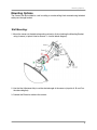
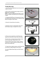
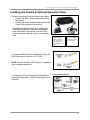
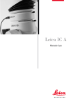
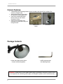
Camera Features
Camera Features
•
•
•
•
Patented Mirroring Technology Makes Camera Invisible to the Human Eye Yet Allows The
Camera to Properly View
Security Mirror Form Factor is Ideal
for Commercial/Retail Applications
Cable Pass-through Wall Mount
Bracket Conceals and Protects
Connection Cables
Ceiling flush mountable or wall
mountable using included cable passthrough bracket.
Ceiling Flush
Mount
Wall Mount
Package Contents
1 x Color Concealed Security Mirror
Camera with Mounting Stand
1 x HEX Adjustment Key
(For Mounting Stand)
WARNING - REGULATED 12V DC 500mA power supply is provided for use with this camera. Use of
a non-regulated, non-conforming power supply can damage this product and will void the warranty.
2
Mounting Options
Mounting Options
The Camera can be installed to a wall or ceiling, or can be ceiling flush mounted using included
cable pass-through bracket.
Wall Mounting:
1. Mount the camera to the desired mounting surface by firmly attaching the Mounting Bracket
using 4 screws (at points listed as Screws 1~4 on the below diagram).
2. Use the Hex Adjustment Key to set the desired angle of the camera (at points A, B and C on
the above diagram).
3. Connect the Extension cable to the camera.
3
Installing the Camera & Optional Extension Cable
Ceiling Mounting:
1. Remove the Mounting Bracket from the back of the
Camera (4 screws)
1
2. Drill a hole in the ceiling large enough to pass the
BNC/Power Cable through.
NOTE: If using the Ceiling Mounting method, run the
Extension Cable to the location prior to mounting the
Camera.
3. Connect the BNC/Power Cable end of the Camera
to the BNC/Power connections on the Extension cable
before installing the Camera Base.
4
4. Screw the Camera Base to the ceiling.
5. Angle the Camera by loosening the side screws.
Set the desired angle, and tighten the screws.
5
6. There are two screw holes on the Dome cover –
align these holes with the screw holes on the base.
6
Once the holes are aligned, adjust the Dome Insert
so that the opening is aligned with the Lens.
Place the Dome Cover over the Camera and Base,
making sure to align the dome cover holes with the
holes on the camera base.
7a. Screw the two side clip screws on the Dome Cover
into the base to hold the dome cover in place.
7a
7b. Use the Rubber Dome Ring to seal the Dome to
the Base.
7b
4
Installing the Camera & Optional Extension Cable
Installing the Camera & Optional Extension Cable
1. Connect the optional Extension cable to the Camera:
• Connect the BNC & Power ends of the cable to
the Camera
• Connect the Power Adaptor connector to the AC
Power Cable attached to the camera.
Remember to check the ends of the cable before
permanent installation, as the power connection
ends are different (one side has a female barrel
power connection, and one end has a male power
plug.
VIDEO INPUT:
Connect the BNC
cable to the video
input of the monitor,
and connect the
power adaptor to an
outlet.
CAMERA:
Connect the BNC
and Power cables
to the Camera
2. Connect the BNC end of the Extension Cable to the
DVR / Observation System or to a TV/VCR.
NOTE: Connect the BNC to RCA Adaptor as needed to
allow for proper connectivity.
3. Connect the A/C Power Adaptor to the Extension
Cable (Black connector). Plug the Power adaptor to a
wall outlet
Camera Setup Diagram
5
Camera Specifications
Camera Specifications
Image Sensor Type
Video Format
Effective Pixels
Horizontal Resolution
Scan System
Sync System
S/N Ratio
Iris
AES Shutter Speed
Min Illumination
Video Output
Audio Output
Lens / Focal Length
FOV (Diagonal)
Termination
IR LED / Night Vision Range
Power Requirement
Power Consumption
Operating Temperature
6
1/3” Color CCD Image Sensor
NTSC
510H x 492V (251K)
420 TV Lines
525 Lines 2:1 Interlace
Internal
More than 52dB without AGC
AES
1/60 ~ 1/120,000
0.2 LUX (Sens-up up to x32)
Composite 1.0Vp-p @ 75ohms
Not Supported
Fixed 3.6mm F2.0
92°
BNC, Power DC Jack
N/A
12V DC ±10%
110mA or 1.4W
14°F ~ 122°F / -10°C ~ 55°C