1
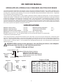
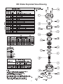
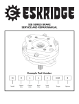
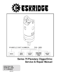
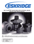
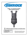
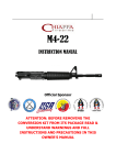
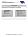
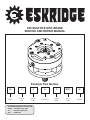
95C MULTIPLE DISC BRAKE SERVICE AND REPAIR MANUAL Example Part Number 95 C 4 A 2 B037 W Series Output Pilot Output Spline Input Pilot Input Spline Torque Code Options THIS SERVICE MANUAL IS EFFECTIVE FROM: ..... S/N 33228, JULY 1983 TO:........... S/N 85377, MAY 2007 REF: ........ SM95C-AF 95C SERVICE MANUAL SPRING-APPLIED, HYDRAULICALLY-RELEASED, MULTIPLE-DISC BRAKE This manual will assist in disassembly and assembly of major components for all Model 95C Brakes. Item numbers, indicated in parentheses throughout this manual, refer to the Eskridge model 95C exploded parts breakdown drawings. Individual customer specifications (mounting case, output shaft, brake assembly, etc.) may vary from exploded drawing and standard part numbers shown. If applicable, refer to individual customer drawing for details. The Model 95C Series Eskridge brake is a spring applied, hydraulically released, multiple disc parking brake. The 95C is designed for "failsafe" type operations. Temperature, wear, and contamination of the friction surfaces will affect the performance of the brake and should be taken into consideration when specifying a required torque rating. Care should be taken to avoid damaging the splines or mounting surfaces during installation. The model 95C is not intended for use in dynamic applications. Please contact Eskridge Sales Dept. about any flow through applications. Brake operation should be tested during normal service operation. Brake inspection and service should be part of the normal service and maintenance schedule of the equipment or vehicle in which it is used. Any loss of holdng torque requires the removal, inspection and replacemnt of suspect components. SPECIFICATIONS Maximum release pressure 3,000 PSI* Maximum operating temperature Maximum continous pressure 3,000 PSI* Volume of oil to release brake Maximum speed at full release pressure 3,900 RPM Approximate weight Shaft splines 30° involute, flat root side fit per ANSI B92.1 internal - class 7, external - class 5 Breakaway torque may vary +/- 10% from specified ratings. Use only mineral base hydraulic oil to release brake. 170° F .5 cu. in. 42 lbs. *5,000 PSI with ‘E’-Extra Pressure option Torque ratings are based on standard friction material in ATF-F fluid media or dry bronze at (0) PSI back pressure. Break away torque may vary+/-10% from specified ratings. The “W” wet option applies to bronze friction discs only and is furnished with mineral base hydraulic oil. Torque rating for wet bronze brakes will vary depending upon the type of oil used. Use only mineral base hydraulic oil for release of brake. For flow-thru option “F”, use only fluids that are compatible with internal seals. Use of fluids other than specified above will alter torque values. ! WARNING: While working on this equipment, use safe lifting procedures, wear adequate clothing and wear hearing, eye and respiratory protection. TORQUE CODE AND OPTIONS 9 5 C 4 A 2 B 03 7 - W Options= F=Flow-thru Ports in housing B=Bronze Friction Discs (Dry) Spring Color Code BW=Bronze Friction Discs (Wet) (Hyd. Oil) G=Green E=Extra System Pressure, Up to 5,000 PSI R=Red Quantity of Separator Plates Y=Gold Quantity of Springs Torque in Ft-Lbs Gear Drive 95C Brake Motor Gasket Hydraulic Gasket/ O-ring 2 Thread Size SAE Grade 5 SAE Grade 8 Dry Lubed Dry Lubed 3/8-16 30 23 45 32 1/2-13 75 55 110 80 5/8-11 150 110 220 170 3/4-10 260 200 380 280 and replaced. Check for wear spots or nicks on the sealing lip of oil seal. Rotate inner race of bearing: rotation should be smooth and without excess drag. Installation NOTE: Before beginning installation procedures, visually inspect brake mounting flanges and shaft splines for damage during shipping. 1) 2) Assembly Position brake and motor for mounting and to orient the bleed and release ports as required. If mounted with shaft horizontal, the bleed port should be at top. It might be necessary to release brake before it can be rotated to align mounting holes. If so, follow instructions in steps 5 and 6 prior to applying release pressure! NOTE: Parts must be clean and dry before assembly. Visually inspect components for damage and abnormal wear. Do not use damaged or worn parts. Use only SAE grade 5 (or better) fasteners for mounting brake and motor. 1) Place brake case ( 1) on a stable work platform, bearing side down. If the oil seal (18) and bearing ( 7) are not being replaced skip to step number 4. 2) Install seal from either side of case, pressing until top of seal is flush with case. Open side of seal should be facing inside of brake. A seal installation tool is recommended. 3) Press in bearing ( 7) from outside. Press against the bearing outer race until the bearing is fully seated in the case. A bearing installation tool is recommended. 4) Support the case in such a way that allows room for the shaft ( 5) to protrude out the bottom. Two pairs of stacked 2 x 6 wood blocks work well. 5) Push the shaft downward through oil seal and bearing until shaft shoulder is seated against bearing. 6) Install spacer (3). 7) Install separator plates (12) and friction discs (11) in exactly the same order as they were removed. There should be a separator on the top and bottom of the stack. Do not place a friction disc next to the piston. Be careful not to contaminate the friction disc or separator plate surfaces with dirt, grease, or fluid other than the brake was designed to use. 8) If replacing piston o-rings (15 & 16) and piston back-up rings (13 & 14), be sure o-rings are nearest each other with backup rings to the outside of the piston (6). Lightly lubricate piston bores and o-rings. Take care not to get lubricant onto friction pack. 9) Gently slide piston into case until larger o-ring touches case. Using a light to medium duty press, push piston completely into bore. This will squeeze the o-rings and back-up rings and set piston against friction pack. 10) Place springs (10) into spring pockets in piston. Arrange springs in a symmetrical pattern. 11) Install thrustwasher (4). 12) For optional double bearing brakes, install bearing into cover (2). 13) Install case seal o-ring (17) onto pilot of cover. 14) Set cover on top of piston, springs, and input end of shaft. 15) Apply a non-hardening thread-locking compound to each cover cap screw (8) and start each one into the case by hand. Tighten cover cap screws 1/2 turn at a time in a crisscross pattern until cover is tight against the case. Tighten to the torque shown in the chart on page 3. A light to medium duty press can be used to push the cover down on to the case so the cover bolts can be installed more easily. 16) The brake is now ready for testing of fit, function and release pressure. Use only mineral based hydraulic oil to test and operate Eskridge multiple disc brakes. Bleed brake before Disassembly 1) Remove any plugs and fittings from the brake pressure and bleed ports. Drain, or blow out, as much hydraulic oil as possible from the brake into a suitable container for proper disposal. 2) Place brake on stable work platform, shaft down. Support the brake so it won't fall over. 3) Remove the four socket head cap screws ( 8) from input end of brake. The capscrews and cover ( 2) are under spring load. The capscrews should be loosened gradually and uniformly. 4) Remove cover. This will expose the internal components of the brake. The case seal o-ring (17) will be attached to the cover pilot. Inspect the o-ring and replace with a new one if worn or damaged. 5) Remove thrust washer (4). 6) Note the color, number, and spacing of the springs (10) then remove them from piston (6). Inspect springs and replace with new ones if damaged, broken or discolored from heat. 7) Support the brake, with shaft up, in such a way that the piston can be pushed out the bottom. Two pairs of stacked 2 x 6 wood blocks work well. 8) Using a soft-faced hammer, drive the shaft (5) and piston down out of the case. 9) Note arrangement of friction discs (11), separator plates (12), and spacer (3). 10) Remove friction discs, separator plates and spacer. Friction discs should be replaced with new ones if oil soaked (dry brakes only). Any friction discs or separator plates that are damaged, warped, or excessively worn should be replaced with new ones. 11) Minimum usable stack height, not including the spacer, is 1.650 inches. If the stack of friction discs and separator plates is less than this they should be replaced. 12) Inspect brake shaft splines and bearing journals for abnormal wear or damage. 13) Remove o-rings (15 & 16) and back-up rings ( 13 & 14) from piston. Replace with new ones if worn or damaged. NOTE: Standard o-rings for 3,000 PSI are black nitrile. Option ‘E’ Extra Pressure o-rings for 5,000 PSI system presurre are light yellow or cream colored urethane. 14) If damaged, the oil seal (18) and bearing (7) can be removed 3 pressurizing. To test release pressure, be sure one of the two hollow hex plugs (9) is installed. Connect a hydraulic power source (either a hand pump or port-a-power) to the other brake port. Bleed air from brake, then pressurize the brake slowly to the advertised release pressure, both initial and full. As you pressurize the brake, rotate the brake shaft. The brake shaft should be able to turn at the advertised initial release pressure (+ or - 25 PSI). There will be drag on the shaft. Increase the pressure slowly until the shaft spins freely, this is the full release pressure. As you pressurize the brake, look for signs of leaks which would indicate that the o-rings or back-up rings may have been damaged during assembly. 95C Repair Kits Due to the many combinations of torques and release pressures available for the 95C, it is impossible to detail each style and supply a repair kit for each individual model. The information listed in this manual is representative of all 95C brakes. The repair kits listed below will work with all combinations of torque vs. release pressure, input mountings and friction plates. It is entirely possible to have "extra" parts left over from the repair kits after you have complete the repair or maintenance. If you are not sure about what is required for your brake and its configuration, please contact Eskridge sales or engineering department. Friction Disc Kit NOTE: Maximum operating pressure is 3,000 PSI with standard nitrile o-rings on pistion and 5,000 PSI with ‘E’ option urethane o-rings. Operation above this pressure is detrimental to the life of the brake and could be dangerous. 95-016-2491 01-288-0072 Friction Disc, Bronze Separator Plate Kit (8) 95-016-2501 01-288-0082 Separator Plate THE BRAKE IS NOW READY FOR USE. Seal Kit - Standard 01-400-0191 01-400-0201 01-402-0601 01-402-0611 01-402-0621 01-402-0010 01-402-0220 01-405-0561 90-004-1061 90-004-1091 90-004-1391 95-016-1181 Back-up Ring, Piston Back-up Ring, Piston O-Ring, Piston O-Ring, Piston O-Ring, Case Seal O-Ring, Mtr.,"C" O-Ring, Mtr.,"B" Shaft Seal Gasket, SAE"A" Gasket, SAE"B"(2bolt) Gasket, SAE"C"(4bolt) Master Rebuild Kit - Standard 95-016-2491 95-016-1181 01-100-0221 95-004-1041 (9) (1) (1) (1) (1) (1) (1) (1) (1) (1) (1) (1) 95-015-3241 Friction Disc Kit, 95C Seal Kit, 95C Bearing Thrust Washer (1) (1) (1) (1) Master Rebuild Kit - Double Bearing Option 95-015-3251 95-016-2491 95-016-1181 01-100-0221 01-100-0231 Friction Disc Kit, 95C Seal Kit 95C Bearing Bearing (1) (1) (1) (1) Option ‘E’-Extra Pressure Option (5,000 PSI) Kits Seal Kit - High Pressure 95-016-1211 Same as standard seal kit but substitute: 01-402-0870 for 01-402-0601 01-402-0880 for 01-402-0611 Master Rebuild Kit - High Pressure 95-015-3291 Same as standard master rebuild kit but substitute: 95-016-1211 for 95-016-1181 Master Rebuild Kit - Double Bearings - High Pressure 95-015-3301 Same as standard master rebuild kit - double bearings but substitute: 95-016-1211 for 95-016-1181 4 95C Brake Exploded View Drawing 85377, MAY 2007 5 Eskridge Product Warranty ESKRIDGE, INC. (“Eskridge”) warrants to its original purchaser (“Customer”) that new component parts/units (“Units”) sold by Eskridge will be free of defects in material and workmanship and will conform to standard specifications set forth in Eskridge sales literature current at the time of sale or to any custom specifications acknowledged by written Customer approval of drawings, SUBJECT TO THE FOLLOWING QUALIFICATIONS AND LIMITATIONS: 1. Prior to placing Units in service, the Customer shall provide proper storage such that foreign objects (e.g., rain or debris) cannot enter any Units via entry ports which are normally closed during operation. 2. The Customer must notify Eskridge in writing of any claim for breach of this warranty promptly after discovery of a defect. The warranty period shall commence when a unit is placed in service and shall expire upon the earlier of a. the expiration of twelve (12) months from the date of Commencement of Service (as defined in Paragraph 4) b. the completion of one thousand (1000) hours of service of the Units c. the expiration of six (6) months after the expiration of any express warranty relating to the first item of machinery or equipment in which the Units are installed or on which it is mounted, or d. the installation or mounting of the Units in or on an item of machinery or equipment other than the first such item in which the Units are installed or on which the Units are mounted. 3. Units shall be deemed to have been placed in service (the “Commencement of Service”) at the time the machinery or equipment manufactured or assembled by the Customer and in which the Units are installed or on which the Units are mounted is delivered to the Customer’s dealer or the original end-user, which ever receives such machinery or equipment first. 4. This warranty shall not apply with respect to Units which, upon inspection by Eskridge, show signs of disassembly, rework, modifications, lack of lubrication or improper installation, mounting, use or maintenance. 5. Eskridge makes no warranty in respect to hydraulic motors mounted on any Units. Failure of any such motor will be referred to the motor manufacturer. 6. Claims under this warranty will be satisfied only by repair of any defect(s) or, if repair is determined by Eskridge in its sole, absolute and uncontrolled discretion to be impossible or impractical, by replacement of the Units or any defective component thereof. No cash payment or credit will be made for defective materials, workmanship, labor or travel. IN NO EVENT SHALL ESKRIDGE BE LIABLE FOR INCIDENTAL OR CONSEQUENTIAL DAMAGES OF ANY KIND OR NATURE, FOR WHICH DAMAGES ARE HEREBY EXPRESSLY DISCLAIMED. 7. From time to time, Eskridge may make design changes in the component Units manufactured by it without incorporating such changes in the component Units previously shipped. Such design changes shall not constitute an admission by Eskridge of any defects or problems in the design of previously manufactured component Units. 8. All freight charges on Units returned for warranty service are the responsibility of the Customer. 1. Any part/Unit(s) returned to Eskridge must be authorized by Eskridge with an assigned return (CSR) number. 2. All Units shall be returned freight prepaid. 3. Any Units qualifying for warranty will be repaired with new parts free of charge (except for freight charges to Eskridge as provided above). 4. If Units are found to be operable, you have two options: Warranty Return Policy a. The Units can be returned to you with a service charge for inspection, cleaning, and routine replacement of all rubber components and any other Units that show wear; b. We can dispose of the Unit(s) at the factory if you do not wish it to be returned. NOTE: Any order of Units by customer shall only be accepted by Eskridge subject to the terms stated herein. Any purchase order forms used by Customer (to accept this offer to sell) which contain terms contrary to, different from, or in addition to the terms herein shall be without effect, and such terms shall constitute material alteration of the offer contained herein under K.S.A 84-2-207 (2)(b), and shall not become part of the contract regarding the sale of the Units. The foregoing warranty is the sole warranty made by Eskridge with respect to any Units and is in lieu of any and all other warranties, expressed or implied. There are no warranties which extend beyond the description on the face hereof without limiting the generality of the foregoing, Eskridge expressly disclaims any implied warranty of merchantability or fitness for any particular purpose, regardless of any knowledge Eskridge may have of any particular use or application intended by the purchaser. The suitability or fitness of the Units for the customer’s intended use, application or purpose and the proper method of installation or mounting must be determined by the customer. 6 ESKRIDGE PRODUCTS Planetary Gear Drives TORQUE RATING (IN-LB) SERIES MODELS 20 28 50 65 100 105 130 150 250 600 20B, 20P, 20LB, 20LP 28B, 28P, 28M, 28LB, 28LP 50K/L, 50LG, 50N 60B, 60E, 60L 100E 105E 130 150 250K/L, 251K/L, 252K/L, 253K/L 600K/L 20,000 50,000 50,000 60,000 100,000 100,000 130,000 150,000 250,000 600,000 1000 100K/L 1,000,000 MAX. INTERMITTENT Multiple Disc Brakes SERIES 90B 90BA 92B 93 95C 95W 98D FEATURES SAE B SAE B, ADJUSTABLE TORQUE SAE B, LOW PROFILE FOR NICHOLS MOTORS SAE C SAE C WHEEL MOUNT SAE D TORQUE RATING (IN-LB) TO 4,800 TO 4,800 TO 2,800 TO 6,100 TO 12,000 TO 21,000 TO 25,000 Planetary Auger Drives, Anchor Drives & Diggers SERIES D50 76 77 78 75 D600 D1000 MODELS 1500, 2500 & 5000 BA & BC, 2-SPEED BA, BC & BD 35 & 48, 2-SPEED 38 & 51, 2-SPEED D600 D1000 TORQUE RATING (FT-LB) 1,500 - 5,000 8,000 - 12,500 6,000 - 12,500 9,000 - 12,500 16,500 - 20,000 50,000 83,000 P. O. Box 875 1900 Kansas City Road Olathe, KS 66051 Phone (913) 782-1238 Fax (913) 782-4206 [email protected] www.EskridgeInc.com