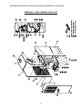
1
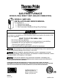
GAS-FIRED FURNACE
DOWN FLOW & DIRECT VENT (SEALED COMBUSTION)
MODELS: GMD1-80N
INSTALLATION AND SERVICE MANUAL
For installation in:
1. Manufactured Homes
2. Modular Homes/Buildings
3. Site Constructed—Residential (Single Story Dwellings)
:
FOR YOUR SAFETY
Do not store or use gasoline or other flammable vapors and liquids in the vicinity of this
or any other appliance.
WHAT TO DO IF YOU SMELL GAS
• Do not try to light any appliance.
• Do not touch any electrical switch; do not use any phone in your building.
• Immediately call your gas supplier from a neighbor’s phone.
Follow the gas supplier’s instructions.
• If you cannot reach your gas supplier, call the fire department.
: If the information in these instructions is not followed exactly, a fire or explosion may
result causing property damage, personal injury, or loss of life.
: Improper installation, adjustment, alteration, service, or maintenance can cause
injury or property damage. Refer to this manual. For assistance or additional information, consult
a qualified installer, service agency, or fuel supplier.
: Do not use this appliance if any part has been underwater. Immediately call a
qualified service technician to inspect the appliance and to replace any part of the electrical or
control system that has been underwater.
PLEASE READ THESE INSTRUCTIONS PRIOR TO INSTALLATION, INITIAL FIRING, AND BEFORE
PERFORMING ANY SERVICE OR MAINTENANCE. THESE INSTRUCTIONS MUST BE LEFT WITH THE USER
AND SHOULD BE RETAINED FOR FUTURE REFERENCE BY QUALIFIED SERVICE PERSONNEL.
THERMO PRODUCTS, LLC.
POST OFFICE BOX 217
NORTH JUDSON, IN 46366
PHONE: (574) 896-2133
MG-505
ECN 4501-MA
MADE IN USA
All installations and services must be performed by qualified service personnel.
I. SAFETY SECTION
This page and the following two pages contain various warnings and cautions
found throughout this furnace Service and Installation Manual. Please read and
comply with the statements on the cover and the statements below.
: This
furnace is not to be used as a construction heater.
: When testing electrical equipment, always follow standard electrical
procedures and precautions.
: The area around the furnace should be kept free and clear of
combustible materials, especially papers and rags.
: This furnace uses an automatic hot surface ignition control. NEVER
try to ignite gas manually.
: If the temperature rise exceeds 85°F, the heat exchanger may fail
voiding the heat exchanger warranty resulting in property damage, personal
injury or loss of life.
: Burner
adjustments must be confirmed by instrumentation. Failure to
use accurate or calibrated instrumentation to setup the burner may result in
reduced efficiency, sooting, and/or the production of hazardous carbon
monoxide gas.
: Any attempt to relocate safety controls or replace safety controls with
a control that is not approved or incompatible, may result in personal injury,
substantial property damage or death.
: If you do not follow these instructions exactly, a fire or explosion may
result causing personal injury, loss of life or property damage.
: HAZARD
OF ASPHYXIATION: Negative pressure inside the closet with
closet door closed and the furnace blower operating shall be no more negative
than minus 0.05 inch water column.
: Do not obstruct any return air openings, including the return grille on
the furnace. To do so may cause the furnace to activate the high limit and shut
down or it may cause asphyxiation.
: Because of the potential of odorant fade, a gas leak may not be
detected by smell. If this furnace is installed below grade, contact your gas
supplier for a gas detector.
: All gas pipe connections must be leak tested using a strong soap and
water solution (with the gas turned on). Any leaks must be repaired immediately
1
All installations and services must be performed by qualified service personnel.
after turning off the gas supply. A final test for gas leakage must be made after
purging the gas line.
: DO
NOT wet electronic components during the leak test. Wetting
electronic components may damage circuitry and cause a hazardous situation.
Dry moisture from all leads and terminals if wetting occurs. Wait at least 24
hours for the circuit to fully dry before energizing the system.
: The furnace and its gas valve must be disconnected from the gas
supply during pressure testing of the gas supply system at pressures in excess
of 1/2 PSIG or 14.0 inches W.G. The furnace can be isolated from the gas supply
by closing its manual shut off valve at test pressures equal to or less than 1/2
PSIG or 14.0 inches W.G.
Copper and brass tubing and fittings (except tin lined) shall not be
used if the gas contains more than a trace (0.3 grains per 100 cubic ft.) of
hydrogen sulfide gas. Check with your gas supplier.
:
: If you suspect there is a problem with the furnace, the venting system
or any other related problem, immediately contact a qualified service agency. If a
service agency is not available, contact your fuel supplier.
: Personal injury, or property damage, could result from major repair or
service of this furnace by anyone other than a qualified contractor. Only the
routine maintenance described in the user section of this manual should be
performed by the user.
: Do
not block or obstruct air openings on the furnace or air openings
communicating with the area in which the furnace is installed.
: Do not allow the outside air intake to be blocked or obstructed by
vegetation, ice, snow or any other materials.
: Do
not use this furnace if any part has been underwater. Immediately
call a qualified service agency to inspect the furnace and to replace any part of
the electrical or control system, which has been underwater.
: Should
overheating occur or the gas supply fail to shut off, shut off the
manual gas supply valve to the furnace before shutting off the electrical supply.
2
All installations and services must be performed by qualified service personnel.
This page and the following page contain reproductions of the various warning
and instruction labels placed on the Thermo Pride Gas Furnace. Please read and
comply with the contents of these labels.
3
All installations and services must be performed by qualified service personnel.
4
All installations and services must be performed by qualified service personnel.
TABLE OF CONTENTS
SECTION
BEGINNING PAGE
I.
II.
III.
IV.
SAFETY SECTION
GENERAL INSTRUCTIONS AND CLEARANCES
FURNACE SPECIFICATIONS
INSTALLATION
A. ROOF JACK
B. STANDARD CHIMNEY
C. FURNACE LOCATION
D. BASE INSTALLATION
1. Combustible Floor Base Model: 70-BASE
2. Cottage Base Model: 01COT-BASE
E. ALCOVE INSTALLATION
F. CLOSET INSTALLATION
G. COMBUSTION AIR
H. GAS PIPING
I. ELECTRICAL WIRING
J. PROPANE CONVERSION
K. INITIAL START UP
L. ADJUSTMENT OF BTU INPUT RATE
M. BURNER ADJUSTMENT
N. SETTING TEMPERATURE RISE
O. FURNACE CHECKOUT PROCEDURE
V.
INSTALLER’S INSTRUCTIONS TO USER
VI.
STARTING THE UNIT
A. SEQUENCE OF OPERATIONS
VII. TROUBLESHOOTING
VIII. DEALER MAINTENANCE
A. ELECTRICAL
B. BURNERS
C. INDUCER BLOWER ASSEMBLY
D. INSPECTING THE VENTING SYSTEM
E. GASKETS/SEALING MATERIALS
F. HEAT EXCHANGER
G. HOUSE AIR BLOWER
H. EXTENDED SHUTDOWN
IX.
USERS INFORMATION SECTION
A. WARNINGS & CAUTIONS
B. COMPONENT LOCATIONS
C. INSPECTION AREAS
D. FILTER LOCATION AND CLEANING
APPENDIX A - REPLACEMENT PARTS LIST
APPENDIX B – WIRING DIAGRAM
5
1
6
8
10
10
10
10
12
12
13
14
15
16
18
19
21
24
24
26
27
27
29
30
30
32
38
38
38
38
39
39
39
39
39
41
41
42
42
43
44
46
All installations and services must be performed by qualified service personnel.
II. GENERAL INSTRUCTIONS AND CLEARANCES
NOTE: READ THIS SECTION BEFORE STARTING INSTALLATION
1. This furnace is equipped with orifices for operation with natural gas. For
conversion to propane gas, see instructions in Gas Conversion Section of this
manual.
2. Any reference to L.P. or Propane gas in this manual, any other labels, or
markings on this furnace is to be construed to be propane HD-5. A commercial
grade of liquefied petroleum gases composed of a minimum of 90 percent liquid
propane (C8H8).
3. The selection of a furnace heating capacity for a proposed installation should be
based on a heat loss calculation made according to the manuals provided by the
Air Conditioning Contractors of America (ACCA) or the American Society of
Heating, Refrigeration and Air Conditioning Engineers, Inc. (ASHRAE).
4. The installer shall be familiar with and comply with all codes and regulations
applicable to the installation of these heating appliances and related equipment.
In lieu of local codes, the installation shall be in accordance with the current
provisions of one or more of the following standards.
a. Federal Manufactured Home Constructions & Safety Standard (HUD Total 24,
Part 280).
b. American National Standard (ANSI-119.2/NFPA-501C), for installations of all
recreational vehicles.
c. American National Standard (ANSI-Z223.1/NFPA-54), for installation of all gasfired furnaces.
d. American National Standard Electric Code (ANSI-C1/NFPA-70), for installation of
all electrical field wiring.
The gas-fired furnace has been investigated under the ANSI Z 21.47-CAN/CGA 22.32001 CENTRAL FURNACE test standard. This gas fired unit is listed by Intertek
Testing Services and described as, “For installation as central furnace special type for
single story dwelling.”
: The area around the furnace must be kept free and clear of
combustible materials, especially papers and rags.
: This
furnace is not to be used as a construction heater.
6
All installations and services must be performed by qualified service personnel.
5. Definitions of "combustible" and "non-combustible" materials as presented in the
1999 version of the National Fuel Gas Code, ANSI Z223.1-1999/NFPA 70-1999, are
as follows:
a. Combustible material:
“...materials made of or surfaced with wood, compressed
paper, plant fibers, or other materials that are capable of
being ignited and burned. Such material shall be
considered combustible even though flame proofed, fireretardant treated, or plastered.”
b. Non-combustible material:
“...material that is not capable of being ignited and
burned; such as material consisting entirely of, or a
combination of, steel, iron, brick, tiles, concrete,
slate, asbestos, glass, and plaster.”
This heating appliance must be installed with clearances to combustible material
surfaces of not less than the minimum distances given below. Also, allow ample
clearances for servicing the furnace for easy access to the air filter, blower assembly,
burner assembly, controls, and vent connections.
MODELS GMD1-80N
FRONT
BACK
SIDES
ROOF JACK
VENT CONNECTOR
TOP
PLENUM SIDES
TOP AND SIDES OF DUCT
BOTTOM OF DUCT
CLOSET
6”
0”
0”
0”
6”
1”
1”
1”
1”
7
ALCOVE
18”
0”
0”
0”
6”
1”
1”
1”
1”
All installations and services must be performed by qualified service personnel.
III. FURNACE SPECIFICATIONS
MODEL
GMD1-80
HEAT INPUT RATE (BTUH)
HEATING CAPACITY (BTUH)
BURNER ORIFICE-NAT. GAS (MM)
BURNER ORIFICE-PROP. GAS (DMS)
GAS SUPPLY PRESSURE (IN.W.G.)
MINIMUM REQUIRED
PROPANE
NATURAL
MAXIMUM ALLOWED
PROPANE
NATURAL
GAS MANIFOLD PRESSURE (IN. W.G.)
PROPANE
NATURAL
VENT PIPE SIZE (INCHES)
DESIGN TEMPERATURE RISE (°F)
SEASONAL EFFICIENCY
(AFUE*, %)
80,000
65,000
2.45
#53
11
5.5
14.0
14.0
10 + 0.3
3.5 + 0.3
4
70
81
*AFUE - INCLUDES STEADY STATE THERMAL EFFICIENCY AND OFF CYCLE
LOSSES.
ELECTRICAL RATINGS AND SETTINGS:
ELECTRICAL SUPPLY: 115 VAC / 60HZ / 1 PHASE
MAXIMUM TIME DELAY TYPE FUSE OR HACR BREAKER RATING: 15 AMPS
TOTAL RATED CURRENT (AMPS): 7.15 (GMD1)
NOMINAL HEAT ANTICIPATOR SETTING -- 0.8 mA (GMD1)
DIMENSIONS & WEIGHTS:
CABINET: WIDTH - 18 IN., DEPTH – 25-1/2 IN., HEIGHT - 57 IN.
NO.70 MOBILE HOME BASE: WIDTH - 18-5/16 IN., DEPTH - 24¼ IN., HEIGHT - 4 IN.
WARM AIR DUCT: WIDTH – 12 IN., DEPTH – 12 IN.
COTTAGE BASE: WIDTH – 18-3/16 IN., DEPTH - 24¼ IN., HEIGHT – 14 IN.
FILTER QUANTITY & SIZE: 1 – 18” x 24 “
APPROXIMATE SHIPPING WEIGHT: 165 LBS.
PRODUCT LISTED UNDER ETL FILE NUMBER –
8
All installations and services must be performed by qualified service personnel.
BLOWER DATA
MANUFACTURER: MORRISON PRODUCTS, INC.
BLOWER MODEL: 10-9, DIRECT DRIVE
NOMINAL MOTOR POWER OUTPUT (HORSEPOWER): 1/3
TYPICAL AIRFLOW @ SPECIFIED EXTERNAL
STATIC PRESSURES (SCFM @. IN.W.G.):
ESP (IN W.C.)
LOW SPEED:
MEDIUM LOW
SPEED:
MEDIUM HIGH
SPEED:
HIGH SPEED:
0.2
0.5
712
640
870
760
1100
886
1258
1003
ALL SPECIFICATIONS ARE SUBJECT TO CHANGE WITHOUT NOTICE.
9
All installations and services must be performed by qualified service personnel.
IV. INSTALLATION
A. ROOF JACK
The roof jack assembly and accessories must be listed by a nationally recognized
testing agency for the appropriate heating fuel.
The roof jack assembly must be installed according to the vent manufacturer’s
instructions prior to the furnace installation. (Refer to Figure 2 for flue location on
furnace.) Adapters for pitched roofs as well as extended barrel length roof jacks are
available from other suppliers.
All vent seams and connections must be sealed with high temperature silicone caulk.
B. STANDARD CHIMNEY
When installed as a central furnace special type for single story dwelling, venting into a
metal vent system approved by a nationally recognized testing agency for the
appropriate heating fuel type is permitted. Lined masonry chimneys are acceptable
when sized appropriately. The minimum chimney size should equivalent to the inside
free area of the 4-inch diameter vent collar exiting the furnace, or 12.5 square inches.
Maximum chimney sizes and acceptable installation practices are referenced in the
following publication. When installing the GMD1-80N, refer to Appendix G of the latest
edition of the installation standard NFPA 54, National Fuel Gas Code.
C. FURNACE LOCATION
1. For best performance, locate the furnace so that it is centralized with respect to the
duct system.
2. This furnace is only intended for installation with free air return through the furnace
door louvers. ?CAUTION:
DO NOT connect a ducted return air system directly to
?
the furnace. Improper installation may create a fire hazard and damage internal
equipment, as well as void all manufacturers’ warranties.
3. This furnace may be installed on combustible flooring when utilizing either the No. 70
counterflow floor base, for below the floor duct systems, or with the cottage base, for
floor level air distribution. See Figures 1A and 1B for depictions of the No. 70 and
the cottage bases.
4. This furnace is listed for closet, alcove, or freestanding applications. All applications
must comply with the requirements of this manual.
10
All installations and services must be performed by qualified service personnel.
Combustible Floor Base
Model: 70-BASE
Figure 1A
Cottage Base
Model: 01COT-BASE
Figure 1B
Coil Cabinet
Model: CE111S
Figure 1C
11
All installations and services must be performed by qualified service personnel.
D. BASE INSTALLATION
1. Combustible Floor Base Model: 70-BASE
Referring to Figure 1A, for applications using a combustion air channel and a supply
air duct, use the base as a template to mark the floor opening locations. See Figure
2 for cutout locations. Cut a square opening in the floor for the supply air duct. Cut
the opening 1-inch larger than the square template opening. Cut the combustion air
duct opening. See Figure 1A for cutout sizes.
Figure 2
Place the bottom base panel in position. Mark the square opening location on the
distribution duct at the connection point of feeder duct. Remove the bottom panel.
Cut an opening in the duct slightly larger than the feeder duct. Cut the feeder duct to
length. (Refer to Figure 3 for location of this cut.) Install the feeder duct. Bend over
each tab. Insure an airtight seal by using high temperature sealant or tape on the
joint. Reinstall the bottom panel over the feeder duct. Insert and secure the
combustion air duct. Put the top panel in place.
?CAUTION:
A combustion air duct must be used. If the underside of the mobile
?
home is skirted or enclosed (e.g. enclosed in a crawlspace), the combustion air
intake should exit through the skirting, or enclosure, if at all possible. All joints
and seams of supply ducts and combustion air ducts must be closed with a
sealing method suitable to the application conditions and temperatures (e.g. high
temperature silicone caulk and/or aluminum tape).
12
All installations and services must be performed by qualified service personnel.
If the combustion air passageway cannot terminate outside of the skirting or
enclosure, a permanent opening with a minimum of 50 square inches of
unobstructed infiltration (free area) for ventilation air must be provided for
adequate combustion. This permanent opening must be located no less than 12
inches from the bottom of the enclosure or skirting.
Figure 3
Slit the corners of feeder duct down to the top of the top panel. If metal projects
more than 1 inch above the top panel, trim the flanges down to 1 inch. While pulling
the top of the distribution duct up with one hand, bend down each side of the feeder
duct tightly to the top panel with the other hand. This assures a tight connection
between the top panel and the feeder duct and that the distribution duct will be full
size. Use high temperature tape and/or high temperature silicone caulking on all
joints and seams to minimize air leakage. Secure the top panel to the floor with two
screws in the front flange.
2. Cottage Base Model: O1COT-BASE
The O1COT-BASE cottage base (Figure 1B) is required for a freestanding cottage
base installation. The cottage base is designed to permit the installation of a 6-inch x
14-inch register in each of the two side panels and the front panel.
13
All installations and services must be performed by qualified service personnel.
?CAUTION:
A permanent opening with a minimum of 50 square inches of
?
unobstructed infiltration (free area) for ventilation and combustion air must be
provided to the interior of the structure. Additional make-up air may need to be
supplied to the interior of the structure to compensate for exhaust fans,
appliances, or vents, which consume air from the interior of the structure.
Refer to the assembly installation instructions included with OM1COT-BASE cottage
base for additional information.
3. Coil Cabinet: CE111S
The CE111S coil cabinet (figure 1C) is for applications requiring air conditioning.
The coil cabinet is designed to have the combustion air brought in from the bottom
thru a duct, supplied with the cabinet. Refer to section G Combustion air of this
manual for further instructions on the combustion air termination and connections.
For additional information refer instructions provided with the CE111S coil cabinet.
E. ALCOVE INSTALLATION
In this application, a minimum of 18
inches of clearance must be provided
to the front of the unit. Refer to Figure
4.
Alcove installations must use the No.
70 mobile home base.
Refer to section
G. COMBUSTION AIR for additional
combustion air requirements.
Figure 4
14
All installations and services must be performed by qualified service personnel.
F. CLOSET INSTALLATION
WARNING: HAZARD OF
ASPHYXIATION: A suction
effect will occur when the
furnace is operating inside the
closet with the closet door
closed. For proper operation,
the furnace blower shall create
no more than a 0.05-inch water
column pressure differential
between the closet and the
adjoining space.
?
Figure 5
1. The return air opening into the closet is to have a minimum free area of 250 square
inches, (refer to Figure 5).
2. The return air opening may be located in the top, the center or (ideally) the bottom of
the closet door, or sidewall.
: Do
not obstruct any return air openings, including the return grille on
the furnace. To do so may cause the furnace to activate the high temperature
limit and shutdown, or it may cause asphyxiation.
3. The cross-sectional area of the return air grille leading into the closet (when located
in the floor or ceiling) shall not be less than 250 square inches.
15
All installations and services must be performed by qualified service personnel.
4. The total free area of openings in the floor or ceiling registers serving the return air
system must be at least 350 square inches. At least one register must be located
where it is not likely to be covered by carpeting, boxes, furniture, or any other
objects.
5. Materials located in the return air system must have a flame spread classification of
200 or less.
6. Wiring materials located in the return air duct system must conform to Article 300-22
of the latest edition of the National Electrical Code, NFPA 70.
7. Gas piping shall not be located in, or extend through, the return air duct system.
8. Refer to section G. COMBUSTION AIR for additional combustion air requirements.
G. COMBUSTION AIR
The furnace requires the proper amount of combustion airflow through the combustion
air intake to combust the fuel cleanly and efficiently. An inadequate combustion air
supply can result in unsafe and erratic operation of the burner, sooting of the
combustion chamber and the heat exchanger, and possibly, offensive fuel odors. Refer
to chapter 5.3 of the National Fuel Gas Code, ANSI Z223.1 / NFPA 54-1999, or latest
edition for application specific combustion air requirements.
The preferred location of the outside combustion air intake terminal (e.g. an optional
stainless steel intake hood, part no.370183) is through the side of the structure, skirting,
or enclosure. An acceptable alternate location is under the structure in the skirted or
crawlspace area providing a minimum of 50 square inches of free area exists around
the perimeter for outside combustion air to be drawn through. The opening of the
termination must be at least 7 inches below the top of the floor.
The 70-base/coil cabinet is shipped with a combustion air duct that must be installed in
the bottom of the base enclosure, before the furnace is installed. This 2-inch by 7-inch
duct is shipped in two pieces. High temperature silicone sealant should be applied to
both vertical seams, before it is snapped together with all four flanges on the same end.
High temperature silicone must be applied to the flanges. The combustion air duct can
then be inserted through the opening in the floor base model no.70. When the
combustion air duct has been inserted completely, secure the duct to the combustion
adapter with self-tapping sheet metal screws, refer to Figure 6. Make certain that the
flanges, duct, and adapter are completely sealed to the burner enclosure base with high
temperature silicone caulk. A 3-inch round to 7-inch x 2-1/4 inch rectangular adapter
plate is supplied with the furnace for adapting the 3-inch round flex combustion air duct
to the 2-inch x 7-inch combustion air duct.
16
All installations and services must be performed by qualified service personnel.
Recommended materials for the combustion air duct are smooth, round, galvanized
steel duct or schedule 20 PVC pipe. The maximum intake duct length allowed is
equivalent to 40-feet of straight duct. Reduce this length by 6-feet for the intake hood
and each 90-degree elbow used, and by 3-feet for each 45-degree elbow used the
combustion air duct. ? CAUTION: Flexible, spiral, or corrugated duct is not
recommended, due to the relatively high-pressure drop associated with air movement
through this type of passageway.
Optional combustion air- a 4” round duct may be used by connecting a 3 x 4 reducer to
the 3” flex duct supplied with the furnace.
Figure 6
17
All installations and services must be performed by qualified service personnel.
H. GAS PIPING
: Because
of the potential of the odorant to fade, a gas leak may not be
detected by smell. If this furnace is installed below grade, contact your gas
supplier for a gas detector.
: With
the gas piping pressurized, all gas piping connections must be
leak tested using a strong soap and water solution. Any leaks must be repaired
immediately after turning off the gas supply. A final test for gas leakage must be
made after purging the gas line.
: DO NOT wet electronic components during the leak test. Wetting
electronic components may damage circuitry and cause a hazardous situation.
Dry moisture from all leads and terminals if wetting occurs. Wait at least 24
hours for the circuit to fully dry before energizing the system.
: The furnace and its gas valve must be disconnected from the gas
supply during pressure testing of the gas supply system at pressures in excess
of 1/2 PSIG (13.9 inches W.G.). The furnace can be isolated from the gas supply
by closing the manual gas shutoff valve serving the appliance at test pressures
equal to, or less than, 1/2 PSIG or (13.9 inches W.G.).
: Copper and brass tubing and fittings (except tin lined) shall not be
used if the gas contains more than a trace (0.3 grains per 100 cubic ft.) of
hydrogen sulfide gas. Check with your gas supplier.
Sizing and installation of fuel lines must be in accordance with federal, state, and local
regulations.
A qualified installer or service person must install all gas piping and perform all required
testing.
Piping from the natural gas meter to the furnace shall be in accordance with
requirements of the local gas utility. Piping from the propane tank to the furnace must
follow the recommendations of the gas supplier. In the absence of local codes
governing gas piping selection and installation, follow the National Fuel Gas Code,
ANSI Z223.1 / NFPA 54-1999, or latest edition.
A readily accessible, manual gas shutoff valve (design-certified for the applicable gas)
with a non-displaceable rotor member shall be installed within six (6) feet of the
furnace.
A pipe union, or flanged connection, shall be provided directly up stream of the burner
to allow burner removal. Unions must be of a ground joint type or flange-jointed type
using a gasket resistant to the corrosive effects of LP gases. Pipe dope or sealant
18
All installations and services must be performed by qualified service personnel.
design-certified to be resistant to the action of the LP gases should be used on all
threaded joints.
The burner is setup to be piped to the gas supply through the left-hand side of the
furnace. For service purposes, it is recommended the gas union be located inside the
furnace.
A drip leg must be used on both propane and natural gas installations immediately
upstream of the furnace in order to trap oil, condensate, and other impurities which
might otherwise lodge in the gas valve, or plug the main burner orifice. A drip leg shall
be provided at the outlet of the gas meter when there is excessive condensation
between the gas meter and the furnace.
Failure to install drip leg(s) may void the manufacturer’s limited warranty on the furnace.
For natural gas, the maximum supply pressure is 14.0 in. W.G. and the minimum
supply pressure, for purposes of input adjustment, is 5.5 in. W.G.
For propane gas, the maximum supply pressure is 14.0 in. W.G. and the minimum
supply pressure, for purposes of input adjustment, is 11.0 in. W.G.
I. ELECTRICAL WIRING
: When
testing electrical equipment, always follow standard electrical
procedures and precautions.
All electrical wiring must be installed in strict accordance with local ordinances and
codes. In the absence of local ordinances and codes, all electrical wiring must conform
to the requirements of the National Electric Code, ANSI/NFPA 70-1999, or latest
edition.
1. Electrical Branch Supply Circuit
Route all electrical wiring to the left side of the furnace. The power supply circuit to
the furnace must be installed and grounded in accordance with the provisions of the
National Electrical Code, ANSI/NFPA-70-1999, or latest edition, and all local codes
having jurisdiction.
2. Connection Of Power Supply Wires
a. Remove the cover from junction box.
b. Insert 115 VAC wires through the strain relief bushing (or conduit connection as
applicable) on the left side of the furnace junction box.
c. Connect the “hot” wire to the black wire.
d. Connect the “neutral” wire to the white wire.
e. Connect the “ground” wire to the green wire.
19
All installations and services must be performed by qualified service personnel.
f. Reinstall and secure the junction box cover with the original mounting screws.
3. Connection Of Room Thermostat Wires
NOTE: Class 1 thermostat wire must be used inside the furnace burner
compartment.
a. Insert 24 VAC wires through the plastic grommet on the left side of the furnace
casing.
b. Connect the thermostat wires to the W/R 50A65-143 control (refer to the wiring
diagram).
c. Connect the thermostat wires to the room thermostat.
IMPORTANT: The room thermostat should be installed 4 to 5 feet above the floor
on an interior wall which is relatively free from direct sources of heat (sunlight or
supply airflow) or exposure to cold (drafts from open windows and doors). The
nominal anticipator setting is 0.8 amperes, for the GMD (refer to the thermostat
literature for additional information).
Five-conductor thermostat wire is recommended for 24 VAC, low-voltage, control
circuit wiring. How ever only 2 wires are required for the furnace (a heating
application only).
Electrical Wire Diameter
Maximum Recommended
Thermostat Wire Length
(AWG)
(Feet)
24
22
20
18
55
90
140
225
Once the furnace is installed, check the thermostat anticipator for proper nominal
setting.
1. Connect a multimeter, capable of reading milliamps (mA), in series
with the low voltage wires to the thermostat.
1. Increase the thermostat setting, or create a “call for heat”.
2. Read the value of the thermostat current, in milliamps.
3. Adjust the heat anticipator of the thermostat to the value read by the
multimeter.
If the heat anticipator is set too high, the furnace may delay activation of a heating
cycle for too long. If the heat anticipator is set too low, the furnace may cycle too
frequently. Either condition may not provide optimal comfort to the homeowner.
20
All installations and services must be performed by qualified service personnel.
J. PROPANE CONVERSION
Parts are included with this furnace to convert from natural to propane gas. See
table 1
This conversion kit shall be installed by a qualified service agency in accordance
with the manufacturer's instructions and all applicable codes and requirements
of the authority having jurisdiction. If the information in these instructions is not
followed exactly, a fire or explosion may result causing property damage,
personal injury, or loss of life. The qualified service agency performing this work
assumes responsibility for the proper conversion of this furnace with this kit."
The installation of this conversion kit must be done only by qualified service personnel.
These instructions must be read in their entirety before converting the furnace. Follow
the start-up and operation section of this manual for instructions on the test fire
subsequent to this conversion. The following instructions will outline the procedure for
converting the existing burner from natural to propane gas.
When making a gas conversion, it is necessary to replace and/or modify several
of the existing components. Table 1, shown below, describes these components
and shows the correct model or size for each type of gas, propane, or natural.
Table 1: Contents of the Thermo Pride Gas Conversion Kits
CONTENTS
QUANTITY
(NAT. TO
PROPANE)
Main Burner Orifice Diameter
3
#53 DMS
(0.0595in)
Gas Valve Pressure Regulator
Kit
(White-Rodgers Part No.)
1
92-0659
21
All installations and services must be performed by qualified service personnel.
MANIFOLD REMOVAL AND ORIFICE CHANGE
: Make sure that pipe dope or sealant certified to be resistant to the action of
liquefied petroleum gases is used on all threaded joints.
: The gas supply shall be shut off prior to disconnecting the electrical power
before proceeding with the conversion.
1. Shut off gas to the furnace at the main manual gas shut off valve and power to the
furnace at the disconnect switch.
2. Disconnect the furnace from the gas supply system at the pipe union.
3. Remove the burner box cover by removing the outer row of screws holding the
cover.
Figure 8
22
All installations and services must be performed by qualified service personnel.
4. Remove the four screws securing the manifold in the burner box. Pull the manifold
far enough out of the burner box to access the burner orifices. (See figure 8)
5. Remove the main burner orifices from the manifold using a 1/2-inch wrench.
Replace the existing main burner orifices with conversion orifices as indicated in
table 1.
6. Refer to the instructions provided in the gas valve conversion kit for regulator spring
change out instructions.
7. Reinstall the manifold into the burner box. Make sure that all orifices go into their
respective burners and the groove of the rubber grommet on the manifold lines up
on the edge of the burner box to seal around the manifold. Secure it with four
screws. (See figure 8).
8. Inspect the seal on the burner box cover and if damaged replace it. Install and
secure the burner box cover. Make sure all the fastening screws are used.
9. Check to make sure that the electrical connections to the gas valve are tight.
10. Check that the plastic hose from the pressure switch is attached securely to the
hose barb at the outlet of the gas valve without being kinked.
: The regulator of the gas valve will not function properly if this hose
connection is not made.
11. Reconnect the furnace to the gas supply.
12. Refer to initial start-up and operating instructions for test fire and burner
adjustments.
23
All installations and services must be performed by qualified service personnel.
K. INITIAL START UP:
This furnace does not have a pilot. It is equipped with a hot surface igniter, which
automatically lights the burner. Do not attempt to light the burner by hand. Check the
following items before the initial start-up.
1. Check all wiring for proper hook up. Tighten any loose connections.
2. Using a soap solution, leak test gas piping connections.
3. Check all tubing connections to the pressure switch, inducer, burner box, and gas
valve and make sure they are connected firmly at all their connection points.
4. Check flue pipe, combustion air inlet, and all joints for tightness and to make sure
there is no blockage.
5. Make sure air filter is in place.
6. Make sure the outside vent and air intakes are installed according to instructions
and are free from blockage.
OPERATING INSTRUCTIONS:
: Turn off power to furnace before it is placed into service. The gas
piping system must have been leak tested by a qualified heating contractor. (See
Section IV, H, of these instructions on the installation of gas piping).
: It may be necessary to purge the air out of the gas line for initial startup of the furnace after installation. A qualified heating contractor should do this.
If excessive gas escapes when purging the gas supply at the union, allow the
area to ventilate for at least 15 minutes before attempting to start the furnace.
Propane gas is especially dangerous because the specific gravity of propane gas
allows it to accumulate at floor level at a dangerous concentration.
: Heat exchanger oil will burn off on initial firing creating an unpleasant
odor. To prevent this odor from occurring more than once, it is suggested that:
1. A window(s) be opened.
2. The thermostat be set at highest setting.
3. The furnace remains running at conditions 1&2 for 30 minutes or until odor
has dissipated.
L. ADJUSTMENT OF HEAT INPUT RATE:
The orifices for this furnace were sized: 1) for natural gas having a heating value of
1025 BTU per cubic foot and a specific gravity of .65, or 2) for liquefied propane gas
with a heating value of 2500 BTU per cubic foot and a specific gravity of 1.55. The
rating label inside the furnace vestibule will specify which gas your furnace is orificed
for. If the furnace is installed at an altitude that is more than 2,000 feet above sea level,
24
All installations and services must be performed by qualified service personnel.
it is mandatory the input to the burner be reduced 4.0% for every 1,000 feet that it is
above sea level. If the furnace is installed at an elevation of 5,000 feet, its input must
be reduced 20.0%. Example: a furnace rated at 80,000
BTU at sea level must be reduced to a firing rate of 64,000 (80,000 x .80 = 64,000) at
an elevation of 5,000 feet. If the furnace is installed at an elevation of 2,000 feet or
less, no reduction in input is required. Your gas supplier may supply you with the
correct orifice sizing information.
To check the heat input rate of your natural gas furnace, allow the unit to operate for 10
to 15 minutes and proceed as follows:
a. Call your gas supplier and ask for the BTU content (heating value) of one cubic foot
of the gas, supplied to the installation area. An alternate approach is to assume a value
of 1025 BTU/Cu Ft, which is the national average.
b. With all other gas appliances turned off and using a stopwatch, clock the time
required for the (small) dial on the gas meter to make one full revolution. The meter
dial will state the cubic feet of flow for one revolution usually one, two or five.
FORMULA: BTU/Cu Ft x Number of Cu Ft x 3600 Seconds = Input BTU/hr
Seconds for one revolution
EXAMPLE: 1025 BTU/Cu Ft x 2 Cu Ft x 3600 = 78,678 BTU Input
93.80 Seconds
Check the model number of the furnace, the input rate, the type of gas, and the
manifold pressure on the rating label located in the burner vestibule. If using the above
example, the furnace is a GMD1-80N model and the input rate is 78,678 BTU/hr. The
input rate would be acceptable because it was within + 2% of the listed input of 80,000.
c. Make sure that the gas supply pressure to the furnace is within the allowable range of
5.5" to 14" WC pressure on natural gas and 11.0" to 14.0" WC on propane gas. The
pressure to the furnace must be checked while the furnace burner and any other gas
appliances on the same supply system are operating, using the 1/8 in. NPT manifold
pressure tap shown in figure 8.
GAS PRESSURE CHART FOR ALL GMD1-80 MODEL FURNACES
SUPPLY PRESSURE
MANIFOLD PRESSURE
NAT
MAX 14” WC
MIN 5.5” WC
3.5 + .3” WC
PROPANE
MAX 14” WC
MIN 11” WC
10.0” + .3” WC
25
All installations and services must be performed by qualified service personnel.
TABLE 2
This gas furnace is equipped with a fixed orifice sized for the manifold pressure shown
on the rating label. The input can only be increased, or decreased, by adjusting the
manifold pressure. Remove the 1/8" threaded pipe plug located on the gas manifold.
Use a U tube manometer or recently calibrated pressure gage to measure the pressure.
To adjust the pressure, remove the screw cap from the regulator on the gas valve and
using the adjustment screw. Decrease the pressure by turning the screw
counterclockwise or increase it by turning the screw clockwise.
? CAUTION: ADJUSTMENTS TO THE LISTED PRESSURE MUST NOT EXCEED
0.3" WC A 0.3" WC adjustment will increase or decrease the input approximately 4.0%.
Replace screw (cap) when adjustment is complete.
The correct input can be assumed if the furnace manifold pressure is the same as that
shown on the rating label if a gas meter is not available for natural gas or the unit is
installed on an unmetered propane gas supply.
Shut off the gas supply to the furnace. Remove the pressure gage and re-install the
pipe plug using a thread compound resistant to the action of LP gases.
If the rated input cannot be obtained with the present orifice at the correct pressure,
your local gas supplier may assist in sizing the proper orifice. Thermo Products
Engineering Department will gladly assist in sizing the orifice if you provide them with
the heating value in BTU per cubic foot and the specific gravity of the fuel gas.
M. BURNER ADJUSTMENT
: The
GMD1-80N furnace model utilizes an in-shot burner design that
does not require an air shutter adjustment (air shutters are not used) for proper
flame characteristics. Burner box access cover must always be secured with all
screws in place and tightened before operating furnace.
This unit is designed to not require any burner adjustment. The flames should be
checked by looking through the sight glass located on the burner box. Burner flames
should be clear, blue, and almost transparent in color. (See Figure 9). NOTE: It is not
unusual to have mostly blue flames with yellow or orange tips visible in the tube for
propane gas.
26
All installations and services must be performed by qualified service personnel.
Figure 9
N. SETTING TEMPERATURE RISE
The GMD1-80N is designed and wired at the factory for a heating blower speed that
should result in an approximate temperature rise of 70°F. The blower motor is wired on
medium low speed for heating mode. The temperature rise through the furnace may
vary depending on the duct system, elevation, heating value, etc. for each installation.
After 10 to 15 minutes of continuous operation, the temperature rise through the
furnace must fall within a range of 55°F to 85°F. If the outlet or supply duct
temperature is too high, check to make sure the return air filter is clean, the return air
registers are free from obstruction, the outlet registers are properly adjusted and clear,
and the supply and return air ducts are open.
The circulating air blower is not moving enough air if the supply air temperature is still
too high. Before proceeding further, turn off the power supply to the furnace and
remove the blower door. The speed of the blower must be increased by changing the
speed tap from the motor (see wiring diagram). This is accomplished by locating the
control panel attached to the blower housing and switching blue (med. low) blower lead,
which should be connected to the “Heat” terminal on the White-Rodgers 50A65-143
control, with one of the higher speed blower leads attached to a terminal marked “Park”.
Be sure to attach any unused blower leads to a terminal marked “Park”. Replace the
blower door and turn on the power supply.
O. FURNACE CHECKOUT PROCEDURE
Before any system of gas piping is finally put into service, it shall be carefully tested to
assure that it is gas tight as indicated in section IV. H. Gas Piping of this manual.
27
All installations and services must be performed by qualified service personnel.
NOTICE: All controls on the unit should be checked for proper functioning prior to the
qualified service personnel leaving the job site. Specifically the following should be
checked:
With furnace in normal heating operation, check to make certain blower will start and
stop automatically under control of integrated fan control.
1. Check safety limit control as follows:
a. Shut off incoming power.
b. Block return air opening or disconnect blower motor leads.
c. Restore power to furnace.
d. Set thermostat above room temperature calling for heat.
e. When high air temperatures are reached in furnace at limit control setting with
blower out of operation, burner should shut off.
f. Shut off electrical power.
IMPORTANT: Remove blockage or reconnect blower motor and restore power.
2. Make certain thermostat will automatically start and stop furnace.
3. Block the flue pipe outlet gradually until the pressure switch functions shutting off
the main burners.
4. Block the inlet gradually until pressure switch functions shutting off the main burners.
IMPORTANT: Remove flue or air inlet blockages when done.
28
All installations and services must be performed by qualified service personnel.
V. INSTALLER'S INSTRUCTIONS TO USER:
After completing the installation, the installer shall inform and/or demonstrate to the
homeowner:
1.
The location of all the instructions in the furnace must be kept along with
instructions for any accessories in the plastic pouch near the furnace.
2.
The location and use of the manual gas shut off valve and furnace electrical
disconnect switch. Instruct user to always shut off gas before shutting off electric
power.
3.
The sequence of operation of the furnace.
4.
The correct operation and maintenance of the appliance as outlined in the Users
Information section of this manual.
5.
That failure to maintain and operate this furnace in accordance with these
instructions could result in hazardous conditions, bodily injury, and property
damage and may void the limited warranty on the furnace.
6.
Review with and encourage the user to read the label reproductions and all
warnings and instructions outlined on the front cover and in sections I, II and III of
this manual and in the Users Information section of this manual.
7.
Recommend the user has a qualified heating contractor inspect the furnace at the
start of each heating season. Inform the user of the frequency of inspection
required for reach item in the User Information Section of this manual.
29
All installations and services must be performed by qualified service personnel.
VI. STARTING THE UNIT
A. SEQUENCE OF OPERATIONS
AT ANY TIME THE
GAS VALVE IS
NOT ENERGIZED
CONTINUOUS SAFE OPERATION CHECK IF FLAME
SIMULATION CONDITION PRESENT OR ROLL-OUT
SWITCH OPENS, SYSTEM ENERGIZES INDUCER
FAN FOR 15 SECONDS AND CIRCULATOR BLOWER
AT HEATING SPEED UNTIL SITUATION CORRECTION
START
THERMOSTAT CALLS FOR
HEAT, CONTACTS CLOSE
CONTROL BOARD ENERGIZED,
INDUCER ENERGIZED
PRESSURE SWITCH SENSES
ADEQUATE DIFFERENTIAL
PRESSURE CONTACTS CLOSE
POWER IS APPLIED TO
THE SILICON NITRIDE
IGNITOR. IGNITOR
WARM-UP IS 20 SECONDS
START TRIAL
FOR IGNITION
POWER INTERRUPTION
SYSTEM SHUTS OFF,
RESTARTS WHEN
POWER IS RESTORED.
AFTER IGNITOR WARM-UP,
THE GAS VALVE IS
ENERGIZED TO OPEN
FLAME MUST BE
DETECTED WITHIN
4 SECONDS IF FLAME
IS DETECTED, THE
DELAY-TO-FAN-ON
TIME BEGINS (45 SECONDS)
30
IF FLAME IS NOT
DETECTED, THE GAS VALVE
IS DE-ENERGIZED, THE
IGNITOR IS TURNED OFF AND
THE CONTROL BOARD CONTROL
GOES INTO "RETRY" SEQUENCE
All installations and services must be performed by qualified service personnel.
MAIN
BURNER
OPERATION
CALL
FOR HEAT
SATISFIED
AFTER DELAY-TO-FAN--ON
PERIOD ENDS, CIRCULATING
AIR FAN IS ENERGIZED AT
HEATING SPEED. THE
(OPTIONAL) ELECTRONIC
AIR CLEANER AND
HUMIDIFIER ARE ENERGIZED.
WHEN THERMOSTAT IS
SATISFIED, CONTACTS
OPEN AND THE GAS
VALVE IS DE-ENERGIZED.
AFTER PROOF OF FLAME
LOSS, INDUCER STARTS
5 SECOND POST SURGE
AND (OPTIONAL) HUMIDIFIER
IS DE-ENERGIZED. THE
DELAY-TO-FAN-OFF PERIOD
BEGINS (180 SECONDS)
AFTER THE DELAY-TOFAN-OFF PERIOD ENDS,
THE CIRCULATING AIR
FAN AND (OPTIONAL)
ELECTRONIC AIR CLEANER
ARE DE-ENERGIZED.
THE RETRY SEQUENCE
PROVIDES A 60 SECOND
WAIT BEFORE IGNITION
RETRY. RETRY IS
ATTEMPTED WITH AN
ADDITIONAL 10 SECONDS
OF IGNITOR WARM-UP TIME.
IF IGNITION ATTEMPT IS
UNSUCCESSFUL, ONE
MORE RETRY WILL BE
MADE BEFORE THE
CONTROL BOARD GOES
INTO SYSTEM LOCKOUT.
IF FLAME IS DETECTED,
THEN LOST, THE CONTROL
BOARD WILL REPEAT THE
INITIAL IGNITION SEQUENCE
FOR A TOTAL OF SIX
RECYCLES. AFTER SIX
UNSUCCESSFUL RECYCLE
ATTEMPTS, THE CONTROL
WILL GO INTO SYSTEM
LOCKOUT.
IF SYSTEM IS IN LOCKOUT, THE
MODULE WILL RESET ITSELF
AFTER 60 MINUTES OR MAY
BE MANUALLY RESET BY
INTERRUPTING THE POWER
TO THE FURNACE AT THE
DISCONNECT OR INTERRUPTING
THE CALL FOR HEAT AT THE
THERMOSTAT. IF THIS DOES
NOT RESTART THE SYSTEM,
REFER TO THE TROUBLESHOOTING
SECTION OF THIS MANUAL.
END OF CYCLE
31
All installations and services must be performed by qualified service personnel.
VII. TROUBLESHOOTING
THIS SECTION IS ONLY TO BE PERFORMED BY TRAINED, QUALIFIED SERVICE
PERSONNEL, AND NOT BY THE FURNACE OWNER.
NOTICE: BEFORE TROUBLESHOOTING, FAMILIARIZE YOURSELF WITH THE
START UP AND CHECKOUT PROCEDURE. ALL INSTALLATION AND
SERVICES MUST BE PERFORMED BY QUALIFIED HEATING CONTRACTORS
When testing electrical equipment, always follow standard electrical
procedures and precautions.
1. Check for line voltage (110-120VAC) to the furnace. If there is no line voltage
applied to the furnace, check that disconnecting switch is “on”, fuses or circuit
breakers have not blown or tripped.
2. Make sure thermostat is “calling for heat”.
3. Check for adequate fuel supply and pressure. Are all the fuel shutoff valves
open?
4. To assist you in troubleshooting this furnace, it is equipped with an integrated
ignition control with diagnostics. These diagnostics evaluate what malfunction
the control system has experienced and will activate a flashing light on the
control in different sequences to help pinpoint the failure.
32
All installations and services must be performed by qualified service personnel.
DIAGNOSTIC FEATURES
: Power must be disconnected before servicing.
The 50A65-143 control continuously monitors its own operation and the operation of the
system. If a failure occurs, the LED will indicate a failure code as shown below. If the
failure is internal to the control, the light will stay on continuously. In this case,
the entire control should be replaced, as the control is not field-repairable.
If the sensed failure is in the system (external to the control), the LED will flash in the
following flash-pause sequences to indicate failure status (each flash will last
approximately 0.25 seconds, and each pause will last approximately 2 seconds).
1 flash, then pause
2 flashes, then pause
3 flashes, then pause
4 flashes, then pause
6 flashes, then pause
7 flashes, then pause
8 flashes, then pause
System lockout
Pressure switch stuck closed
Pressure switch stuck open
Open limit switch or rollout switch
115 Volt AC power reversed
Low flame sense signal
Check igniter or improper grounding
Continuous flashing
(No pause)
Flame has been sensed when
no flame should be present
(No call for heat)
The LED will also flash once at power-up.
33
All installations and services must be performed by qualified service personnel.
TROUBLESHOOTING GUIDE
THE SYSTEM IS STARTED BY SETTING THE THERMOSTAT TO CALL FOR
HEAT. THE FOLLOWING SHOULD HELP ESTABLISH THE TYPE OF
MALFUNCTION OR DEVIATION FROM THE NORMAL OPERATION.
TO USE THIS DIAGRAM, FOLLOW THE INSTRUCTIONS IN THE BOXES.
TURN THERMOSTAT TO CALL FOR HEAT
DOES THERMOSTAT MAKE CONTACT?
No
Yes
IS ROOM TEMPERATURE
BELOW THERMOSTAT
SETTING?
No
IS ROOM
TEMPERATURE
ABOVE
90 DEGREES F?
TURN T'STAT
SETTING ABOVE
ROOM TEMP.
No
Yes
COOL THE THERMOSTAT
Yes
IS THE TRANSFORMER
SUPPLYING 24 VOLTS
TO THE THERMOSTAT?
No
ARE WIRES CONNECTED
PROPERLY?
Yes
No
CORRECT WIRE
CONNECTIONS
Yes
REPLACE
THERMOSTAT
IS INTERNAL DAMAGE
PRESENT ON THE
TRANSFORMER?
No
CHECK INPUT
POWER, SERVICE
SWITCH AND FUSES
Yes
REPLACE TRANSFORMER
IS THE INDUCER
BLOWER OPERATING?
No
IS THERE 24 VOLTS
ACROSS "TH" & "TR"
AT THE INTEGRATED
CONTROL?
Yes
Yes
34
No
CHECK FOR
CONTINUITY
& PROPER
CONNECTIONS
All installations and services must be performed by qualified service personnel.
Yes
Yes
IS THERE LINE VOLTAGE
ACROSS INDUCER POWER
TERMINALS "IND" & "IND N"
AT THE INTEGRATED CONTROL?
No
CHECK THE INTEGRATED
CONTROL DIAGNOSTIC LED
LAMP. RESET BY INTERRUPTING
POWER TO CONTROL FOR MORE
THAN ONE SECOND. IF LED STAYS
ON CONTINUOUSLY, REPLACE
INTEGRATED CONTROL.
Yes
CHECK WIRING TO INDUCER
AND IF OK, REPLACE
INDUCER ASSEMBLY.
DOES THE HOT
SURFACE
IGNITOR ENERGIZE
AND GLOW?
No
IS THERE LINE VOLTAGE
ACROSS HOT SURFACE
IGNITOR TERMINALS
"IGN" & "IGN N" AT THE
INTEGRATED CONTROL?
No
CHECK THE INTEGRATED CONTROL
DIAGNOSTIC LED LAMP. RESET BY
INTERRUPTING POWER TO CONTROL
FOR MORE THAN ONE SECOND. IF
LED STAYS ON CONTINUOUSLY
REPLACE INTEGRATED CONTROL.
Yes
CHECK WIRING TO HOT
SURFACE IGNITOR AND
IF OK, REPLACE HOT
SURFACE IGNITOR ASSEMLBY.
Yes
AFTER HOT
SURFACE IGNITOR
WARM-UP, DOES
GAS VALVE OPEN?
No
CHECK ACROSS "MV"
TERMINALS ON INTEGRATED
CONTROL FOR 24 VOLTS DURING
THE 4 SECOND FLAME PROVING
PERIOD AFTER IGNITOR WARM-UP.
IS THERE 24 VOLTS?
Yes
Yes
CHECK WIRING TO GAS
VALVE AND IF OK,
REPLACE GAS VALVE.
35
No
SAME AS ABOVE
All installations and services must be performed by qualified service personnel.
Yes
AFTER GAS VALVE
OPENS, DO THE
BURNERS IGNITE?
MEASURE MANIFOLD
PRESSURE. IS
PRESSURE ADEQUATE?
No
No
ADJUST TO 3.5" WC FOR
NATURAL GAS OR 10.0" WC
FOR PROPANE GAS
Yes
CHECK IGNITOR
VOLTAGE DURING
20 SECOND WARM-UP,
IT SHOULD BE AT
LEAST 105 VOLTS.
Yes
No
CORRECT LINE
VOLTAGE PROBLEM.
Yes
IS IGNITOR
POSITIONED
CORRECTLY?
DO BURNERS STAY
LIT PAST PROOF
OF FLAME CHECK?
No
No
REPOSITION TO
CORRECT LOCATION.
CHECK FLAME
PROVING CIRCUIT
Yes
DOES THE INTEGRATED
CONTROL ENERGIZE THE
CIRCULATING AIR
BLOWER AFTER THE 45
SECOND TIME DELAY?
No
CHECK ACROSS THE
CIRCULATING AIR
BLOWER TERMINALS
"CIR N" & "HEAT"
FOR PROPER VOLTAGE.
No
Yes
DOES THE CIRCULATING
AIR FAN COME ON
WHEN ENERGIZED?
No
DOES BLOWER
SPIN FREELY?
No
Yes
Yes
IS CAPACITOR
WORKING PROPERLY?
No
REPLACE CAPACITOR
36
Yes
REPLACE THE
INTEGRATED CONTROL.
CONFIRM IF EITHER
BLOWER WHEEL IS
RUBBING AGAINST
HOUSING OR MOTOR
SHAFT IS SPINNING
FREELY AND REPAIR
OR REPLACE AS
NECESARRY.
REPLACE MOTOR
All installations and services must be performed by qualified service personnel.
Yes
DOES SYSTEM RUN UNTIL
THERMOSTAT IS SATISFIED?
No
IS LED LIGHT
ON INTEGRATED
CONTROL FLASHING?
No
CHECK ALL
WIRING FOR
LOOSE
CONNECTIONS
Yes
Yes
DOES BURNER SHUT OFF
WHEN THERMOSTAT IS
SATISFIED?
No
CHECK FOR SHORT IN
WIRE TO THERMOSTAT
AND CORRECT IF
NECESSARY.
IF LED FLASHES:
Yes
DOES THE CIRCULATING
AIR BLOWER TURN OFF
AFTER THERMOSTAT IS
SATISFIED WITHIN
120 SECONDS?
1 FLASH, THEN PAUSE SYSTEM LOCKOUT
2 FLASHES, THEN PAUSE
PRESSURE SWITCH STUCK CLOSED
3 FLASHES, THEN PAUSE
PRESSURE SWITCH STUCK OPEN
4 FLASHES, THEN PAUSE
OPEN LIMIT SWITCH OR ROLLOUT SWITCH
6 FLASHES, THEN PAUSE
115 VOLT AC POWER REVERSED
7 FLASHES, THEN PAUSE
LOW FLAME SENSE SIGNAL
8 FLASHES, THEN PAUSE
CHECK IGNITOR OR IMPROPER GROUNDING
CONTINUOUS FLASHING
(NO PAUSE)
FLAME HAS BEEN SENSED WHEN NO FLAME
SHOULD BE PRESENT (NO CALL FOR HEAT)
THE LED WILL ALSO FLASH ONCE AT POWER-UP.
Yes
CHECK COMPLETE SYSTEM OUT.
LED LIGHT STAYS ON CONTINUOUSLY,
COMPLETE FAILURE - REPLACE INTEGRATED CONTROL.
TROUBLESHOOTING COMPLETE.
37
All installations and services must be performed by qualified service personnel.
VIII. DEALER MAINTENANCE
A qualified heating contractor should perform the following maintenance
procedures at the beginning of each heating season. Correct any deficiencies at
once.
? WARNING: Personal injury or property damage could result from repair or
service of this furnace by anyone other than a qualified heating contractor. Only
the homeowner/user routine maintenance described in the Users Information
Manual may be performed by the user.
? WARNING: To avoid injury from moving parts, shut off the power to the
furnace before removing blower compartment door.
? CAUTION: Label wires prior to disconnection when servicing controls. Wiring
errors can cause improper and dangerous operation.
A. ELECTRICAL:
1. Check all wiring for loose connections and any signs of damage or unusual wear.
2. Check for correct voltage at the furnace when operating.
3. Check amp-draw on blower motor and inducer motor to assure they are not
exceeding nameplate amp rating.
4. Check for correct operation and proper settings (if manually adjustable) of all
controls.
Shut off gas and disconnect power before continuing.
B. BURNERS
If it appears that material is accumulating in the burner box, the burner box cover can
be removed and the box and burners can be vacuumed. If necessary, the burners
assembly can be removed by taking out the two screws/one on each bracket on top of
burner box and removing the burner manifold assembly. Assembly must be pulled &
tilted down in order to remove from box. If necessary, the individual tubes can be
cleaned out using compressed air to blow out the individual tubes. Care must be taken
not to damage the igniter.
C. INDUCER BLOWER ASSEMBLY
Inspect the pressure switch and tubing connections and inspect the blower/assembly
for warpage, deterioration and carbon or other build-up. If necessary, clean the
accessible portions of the housing and blower with a damp cloth. Vacuum to remove
any lint or dust from the motor assembly.
38
All installations and services must be performed by qualified service personnel.
D. INSPECTING THE VENTING SYSTEM
The venting system should be inspected during the annual maintenance check-up or
during each subsequent service call.
Check all vent pipes for restrictions due to soot, or carbon build-up, as well as foreign
matter, or any materials, that cause the venting system to restrict the proper venting of
combustion products. If a restriction is found, the flue vent must be cleaned or
replaced to ensure proper venting.
Vent pipes should also be inspected for any signs of corrosion, deterioration, or leakage
that may cause combustion by-products to infiltrate the home or indoor environment.
If signs of corrosion, deterioration, or leakage are evident, the vent pipe must be
replaced with a properly sized, agency-approved, vent pipe.
E. GASKETS/SEALING MATERIALS
Inspect all visible gaskets for signs of degradation, especially any seals which were
removed as part of the inspection. Replace any suspect gaskets.
F. HEAT EXCHANGER
Inspect for corrosion, pitting, warpage, deterioration, carbon build-up, and loose gaskets
in the flue pipe, burner box, and accessible areas of the heat exchanger.
G. HOUSE AIR BLOWER
Check and clean the blower wheel, housing, and compartment with a vacuum. Check
the motor nameplate and follow the motor manufacturers instructions for lubrication, if
required.
IMPORTANT: Some motors are permanently lubricated and should not be oiled.
See motor nameplate for specific instructions.
H. EXTENDED SHUTDOWN
If this furnace is shut down or off for an extended period of time, several steps can be
taken to help insure a smooth and reliable start.
ON SHUT DOWN:
1. Close the gas supply shutoff valve(s).
2. Turn the furnace power switch “off” and disconnect electrical power to the unit.
39
All installations and services must be performed by qualified service personnel.
ON START-UP:
8. Have the heating system (and furnace) inspected and started by a qualified
service person.
9. Set the room thermostat above room temperature.
10. Open all shutoff valves in the gas supply line.
4. Turn “on” the main power at the disconnecting switch and at the furnace power
switch to start the inducer.
5. Follow the “BURNER OPERATION AND ADJUSTMENT” procedure in Section L.
40
All installations and services must be performed by qualified service personnel.
IX. USER INFORMATION SECTION
A. WARNINGS AND CAUTIONS:
: If you suspect there is a problem with the furnace, pertaining to the
venting system or any other related problem, immediately contact a qualified
service agency. If a service agency is not available, contact your fuel
supplier.
: Personal injury or property damage could result from major repair
or service of this furnace by anyone other than a qualified contractor. The
user should only perform the routine maintenance described in the user
section of this manual.
: The
area around the furnace should be kept free and clear of
combustible materials, especially papers and rags.
: Do
not block or obstruct air openings on the furnace casing. Do not
block or obstruct air openings communicating within the area in which the
furnace is installed.
: Do
not allow the outside air intake to be blocked or obstructed by
vegetation, ice, snow, or any other materials.
: Do
not use this furnace if any part has been underwater.
Immediately call a qualified service agency to inspect the furnace and to
replace any part of the electrical or control system, which has been
underwater.
: Should
overheating occur or the fuel supply fail to shut off, shut off
the manual fuel supply valve to the furnace before shutting off the electrical
supply.
41
All installations and services must be performed by qualified service personnel.
B. COMPONENT LOCATIONS
The following diagram shows a typical furnace installation and typical position of
the components referenced in these instructions.
Figure 10
C. INSPECTION AREAS
IMPORTANT: For safe operation it is the responsibility of the owner and/or user
that the burner, chimney/vent pipe, heat exchanger and controls should be
inspected every year by a qualified heating contractor.
42
All installations and services must be performed by qualified service personnel.
1. VESTIBULE: The furnace vestibule areas or burner compartment should be
inspected by removing front door of the furnace and looking for signs of
excessive heat such as discoloration of components, materials damaged
from rust or corrosion, soot or carbon build-up.
2. EXTERIOR OF FURNACES: The furnace exterior should be inspected for
signs of excessive heat such as discoloration of materials or damage from
rust or corrosion.
3. VENT CONNECTOR: The furnace vent pipe should be inspected for signs of
rust, corrosion pitting, or holes in the pipe. Check for leakage around seams
in pipe indicated by soot or condensate streaks.
4. ROOF JACKS: The furnace roof jack should be inspected for signs of rust or
corrosion, pitting or holes, signs of excessive condensation or moisture
leaking from roof jack.
D. FILTER LOCATION AND CLEANING
? CAUTION: To avoid injury from moving part, hot surfaces or electrical
shock, shut off the power to the furnace and allow the furnace to cool
before removing furnace access door to service filter.
The air filter should be inspected each month and cleaned when dirty. Clean the
filter by soaking it in water with a mild detergent and rinsing it with clean water.
Allow the filter to air dry before reinstalling it in the furnace. Cleaning the air filter
frequently may prevent airborne contaminants from going through the furnace
and depositing in the furnace, duct system, and interior of the building.
See Figure 10, in this section, for the location of the return air filter.
43
All installations and services must be performed by qualified service personnel.
APPENDIX A. REPLACEMENT PARTS LIST
44
All installations and services must be performed by qualified service personnel.
45
All installations and services must be performed by qualified service personnel.
APPENDIX B – WIRING DIAGRAM
46