1
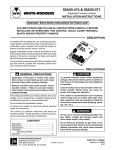
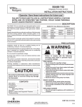
50A62-820
WHITE-RODGERS
Integrated Furnace Control
INSTALLATION INSTRUCTIONS
Operator: Save these instructions for future use!
FAILURE TO READ AND FOLLOW ALL INSTRUCTIONS CAREFULLY BEFORE
INSTALLING OR OPERATING THIS CONTROL COULD CAUSE PERSONAL
INJURY AND/OR PROPERTY DAMAGE.
DESCRIPTION
The 50A62-820 is an automatic gas interrupted ignition
control that employs a microprocessor to continually
monitor, analyze, and control the proper operation of the
gas burner, inducer, and fan.
Signals interpreted during continual surveillance of the
thermostat and flame sensing element initiate automatic
ignition of the burner, sensing of the flame, and system
shut-off during normal operation.
These controls incorporate system fault analysis for quick
gas flow shut-off, coupled with automatic ignition retry
upon sensing a fault correction.
PRECAUTIONS
! CAUTION
! GENERAL PRECAUTION
Application of this type of control may cause
flame rollout on initial start-up and could cause
personal injury and/or property damage.
Replace only with exact model number, including dash number. Failure to use exact replacement control could cause personal injury and/or
property damage.
If in doubt about whether your wiring is millivolt, line, or low
voltage, have it inspected by a qualified heating and air
conditioning contractor, or licensed electrician.
Do not exceed the specification ratings.
To prevent electrical shock and/or equipment
damage, disconnect electric power to system at
main fuse or circuit breaker box until installation
is complete.
Label all wires prior to disconnection when servicing controls. Wiring errors can cause improper and dangerous operation.
This control is not intended for use in locations
where it may come in contact with water. Suitable protection must be provided to shield the
control from exposure to water (dripping, spraying, rain, etc.).
All wiring must conform to local and national electrical
codes and ordinances.
This control is a precision instrument, and should be
handled carefully. Rough handling or distorting components could cause the control to malfunction.
CONTENTS
Description .........................................................
Precautions ........................................................
Specifications .....................................................
Installation ..........................................................
Mounting & Wiring
Operation ...........................................................
WHITE-RODGERS
EMERSON ELECTRIC CO.
9797 REAVIS ROAD
ST. LOUIS, MISSOURI 63123-5398
www.white-rodgers.com
1
1
2
3
!
WARNING
Do not use on circuits exceeding specified voltage. Higher voltage will damage control and
could cause shock or fire hazard.
Do not short out terminals on gas valve or primary control to test. Short or incorrect wiring will
damage thermostat and could cause personal
injury and/or property damage.
6
PART NO. 37-6266A
Printed in U.S.A.
0119
SPECIFICATIONS
ELECTRICAL RATINGS [@ 77°F (25°C)]:
Input Voltage: 25 VAC 50/60 Hz
Max. Input Current @ 25 VAC: 0.455 amp
Relay Load Ratings:
Valve Relay: 1.5 amp @ 25 VAC 50/60 Hz 0.6 pf
Ignitor Relay: 2.0 amp @ 120 VAC 50/60 Hz
(resistive)
Flame Current Requirements:
Minimum current to insure flame detection: 1 µa DC*
Maximum current for non-detection: 0.1 µa DC*
Maximum allowable leakage resistance: 100 M ohms
TIMING SPECIFICATIONS
(All times are in seconds, unless noted otherwise)
50A62-820
PRE-PURGE
15
TRIAL FOR IGNITION
PERIOD
4
IGNITION ACTIVATION
PERIOD
4
RETRIES
*Measured with a DC microammeter in the flame probe
lead
4 times
VALVE SEQUENCE
PERIOD
12
OPERATING TEMPERATURE RANGE:
-40° to 175°F (-40° to 80°C)
INTERPURGE
15
POST-PURGE
5
HUMIDITY RANGE:
5% to 93% relative humidity (non-condensing)
LOCKOUT TIME
122
HEAT DELAY-TO-FAN-ON
45
MOUNTING:
Surface mount multipoise
HEAT DELAY-TO-FAN-OFF*
Timing Specs: (@ 60 Hz)
Flame Establishing Time:
Flame Failure Response Time:
maximum
2 sec
2 sec
Gases Approved: Natural, Manufactured, Mixed, Liquid
Petroleum, and LP Gas Air Mixtures are all approved for
use.
2
60/90/
120/180
COOL DELAY-TO-FAN-ON
0
COOL DELAY-TO-FAN-OFF
0
IGNITOR WARM-UP
20
HUMIDIFIER
YES
ELECTRONIC AIR
CLEANER
YES
* This time will vary depending on option
switch position. The control is factory-set
at 60 sec. heat delay-to-fan-off. See
OPERATION section for further
information.
INSTALLATION
MOUNTING AND WIRING
!
WARNING
NOTE
Replace 50A62 control as a unit - no user serviceable
parts.
Do not use on circuits exceeding specified voltage. Higher voltage will damage control and
could cause shock or fire hazard.
All wiring should be installed according to local and
national electrical codes and ordinances.
! CAUTION
The control must be secured to an area that will experience a minimum of vibration and remain below the maximum ambient temperature rating of 175°F. The control is
approved for minimum ambient temperatures of -40°F.
The 50A62 control may be mounted only in a control box
of a Lennox furnace.
To prevent electrical shock and/or equipment
damage, disconnect electric power to system at
main fuse or circuit breaker box until installation
is complete.
Any orientation is acceptable.
Failure to earth ground the appliance or reversing the neutral and hot wire connection to the line
can cause shock hazard.
Refer to the wiring diagram and wiring table when connecting the 50A62 control to other components of the
system.
Shut off main gas to heating system until installation is complete.
UL approved, 105°C rated 18 gauge, stranded, 2⁄64” thick
insulation wire is recommended for all low voltage safety
circuit connections. Refer to 50A62 specification sheet
for recommended terminals to mate with those on the
control.
Route and secure all wiring as far from flame
as practical to prevent fire and/or equipment
damage.
UL approved 105°C rated 16 gauge min., stranded, 4⁄64”
thick insulation wire is recommended for all line voltage
connections. Refer to 50A62 specification sheet for
recommended terminals to mate with those on the
control.
After installation or replacement, follow appliance
manufacturer’s recommended installation or service
instructions to ensure proper operation.
3
TYPICAL SYSTEM WIRING DIAGRAM
HOT
(LINE)
NEUTRAL
(LINE)
120 VAC
24 VAC CLASS II
TRANSFORMER
TH
24 VAC
TR
50A62
COOL
HEAT
FAN
M1
M2
LINE
XFMR
EAC
HUM
CIRCULATOR
BLOWER
INDUCER
IND
IGN
IGNITOR
HUMIDIFIER
GND
GND
ELECTRONIC
AIR CLEANER
CIR N
LINE N
XFMR N
HUM N
EAC N
Y
Y
W
W
G
G
R
R
C
FLAME
SENSOR
PROBE
THERMOSTAT
FP
PRESSURE SWITCH
(N. O.)
PS
PS
HL
RO1
GND
RO2
MV
MV
TR
TH
LEGEND
Low Voltage (24 VAC)
Line Voltage (120 VAC)
N. C. = Normally closed switch
N. O. = Normally open switch
4
COMPRESSOR
CONTACTOR
HIGH LIMIT
(N. C.)
ROLLOUT
(N. C.)
GAS
VALVE
TYPICAL SYSTEM WIRING TABLE
50A62
TERMINAL
TERMINAL
TYPE
SYSTEM COMPONENT
CONNECTION
W
captive screw
low voltage thermostat W terminal (or equivalent)
G
R
captive screw
low voltage thermostat G terminal (or equivalent)
low voltage thermostat R terminal (or equivalent)
captive screw
Y
C
low voltage thermostat Y terminal (or equivalent)
captive screw
2nd wire from Y terminal goes to 24 VAC HOT side of
compressor contactor coil
captive screw
24 VAC COMMON side of compressor contactor coil
MV (2 terminals)
RO1
gas valve (both gas solenoids are connected in parallel)
rollout switch OUTPUT
RO2
rollout switch INPUT
PS
PS
GND
9-pin
connector
& harness
HL
pressure switch INPUT
pressure switch OUTPUT
MUST BE RELIABLY GROUNDED TO CHASSIS
high limit switch input
(unused terminal)
IND
IGN
GND
GND
(unused 2 terminals)
COOL
HEAT
M1
M2
FAN
LINE
XFMR
CIR N
LINE N
XFMR N
HUM
EAC (optional)
HUM N
EAC N (optional)
TR
TH
FP
inducer HOT side
6-pin
connector
& harness
spade terminal
spade terminal
spade terminal
spade terminal
spade terminal
spade terminal
spade terminal
spade terminal
spade terminal
spade terminal
spade terminal
spade terminal
spade terminal
spade terminal
spade terminal
spade terminal
spade terminal
ignitor HOT side
inducer NEUTRAL side
ignitor NEUTRAL side
circulator blower COOL SPEED terminal
circulator blower HEAT SPEED terminal
unused circulator blower terminal
unused circulator blower terminal
circulator blower FAN SPEED terminal
input voltage (120 VAC) HOT side
24 VAC transformer line voltage HOT side
circulator blower NEUTRAL terminal
input voltage (120 VAC) NEUTRAL side
24 VAC transformer line voltage NEUTRAL side
humidifier HOT side
electronic air cleaner HOT side
humidifier NEUTRAL side
electronic air cleaner NEUTRAL side
24 VAC transformer (low voltage COMMON side)
24 VAC transformer (low voltage HIGH side)
flame sensor port*
* maximum recommended flame probe wire length is 36 inches.
5
OPERATION
OPTION SWITCHES
The option switches on the 50A62-820 control are used to
determine the length of the heat delay-to-fan-off period.
The following table shows the time periods that will result
from the various switch positions.
OPTION SWITCH POSITIONS
HEAT delayto-fan-off:
180 sec.
120 sec.
90 sec.
60 sec.*
Set switch
#1
#2
On
On
Off
Off
On
Off
On
Off
* Factory setting
HEAT MODE
In a typical system, a call for heat is initiated by closing the
thermostat contacts. This starts the 50A62 control’s heating sequence. The inducer blower and humidifier are
energized (if there is an optional electronic air cleaner on
the system, the humidifier is not energized until the
electronic air cleaner is energized). The 768A Silicon
Nitride ignitor is powered within one second.
This controller has an adaptive algorithm that reduces the
ignitor temperature to slightly greater than the minimum
temperature required to ignite gas in each particular
application. The control measures the line voltage and
determines an initial ignitor temperature setting based on
the measurement. After each successful ignition, the
control lowers the ignitor temperature slightly for the next
ignition attempt. The control continues to lower the ignitor
temperature until ignition does not occur, and the control
goes into retry mode. For the second attempt to ignite gas
within the same call for heat, the control increases the
ignitor temperature to the value it was on the third previous successful ignition. After ignition is successful, the
control sets the ignition temperature at this value for the
next 255 calls for heat, after which the control repeats the
adaptive algorithm. The control is constantly making
adjustments to the ignitor temperature to compensate for
changes in the line voltage.
The 80 VAC Silicon Nitride ignitor manufactured by
White-Rodgers must be used. These ignitors are specially designed to operate with the 50A62’s adaptive
ignition routine to ensure the most efficient ignitor temperature.
At the end of the ignitor warm-up time, both valves in the
36E manifold gas valve are opened. Flame must be
detected within 4 seconds.
If flame is detected, the delay-to-fan-on period begins.
After the delay-to-fan-on period ends, the circulator fan is
energized at heat speed. If there is an optional electronic
air cleaner on the system, the electronic air cleaner and
the humidifier are energized. When the thermostat is
satisfied, the gas valve is de-energized. After proof of
6
flame loss, the inducer blower remains energized to purge
the system for 5 seconds. When the purge is complete,
the inducer blower and humidifier are de-energized and
the delay-to-fan-off period begins. After the delay-to-fanoff period ends, the circulator fan and electronic air
cleaner are de-energized.
If flame is not detected, both valves are de-energized, the
ignitor is turned off, and the 50A62 control goes into the
“retry” sequence. The “retry” sequence provides a 15second wait following an unsuccessful ignition attempt
(flame not detected). After this wait, the ignition sequence
is restarted. If this ignition attempt is unsuccessful, one
more retry will be made before the control goes into
system lockout.
If flame is detected, then lost, the 50A62 control will repeat
the initial ignition sequence for a total of three “recycles”.
After three unsuccessful “recycle” attempts, the control
will go into system lockout.
If flame is established for more than 10 seconds after
ignition, the 50A62 controller will clear the ignition attempt
(or retry) counter. If flame is lost after 10 seconds, it will
restart the ignition sequence. This can occur a maximum
of five times before system lockout.
During burner operation, a momentary loss of power of 50
milliseconds or longer will de-energize the main gas
valve. When power is restored, the gas valve will remain
de-energized and a restart of the ignition sequence will
begin immediately.
A momentary loss of gas supply, flame blowout, or a
shorted or open condition in the flame probe circuit will be
sensed within 2 seconds. The gas valve will de-energize
and the control will restart the ignition sequence. Recycles will begin and the burner will operate normally if the
gas supply returns, or the fault condition is corrected,
before the last ignition attempt. Otherwise, the control will
go into system lockout.
If the control has gone into system lockout, it may be
possible to reset the control by a momentary power
interruption of one second or longer. Refer to PRECAUTIONARY, SYSTEM LOCKOUT, AND DIAGNOSTIC
FEATURES.
COOL MODE
In a typical system, a call for cool is initiated by closing the
thermostat contacts. This starts the 50A62 control’s cooling sequence. The compressor is energized and the cool
mode delay-to-fan-on period begins. After the delay-tofan-on period ends, the circulator fan is energized at cool
speed. The electronic air cleaner (optional) is also energized. After the thermostat is satisfied, the compressor is
de-energized and the cool mode delay-to-fan-off period
begins. After the delay-to-fan-off period ends, the circulator fan and electronic air cleaner (optional) are de-energized.
MANUAL FAN ON MODE
SYSTEM LOCKOUT FEATURES
If the thermostat fan switch is moved to the ON position,
the circulator fan (fan speed) and optional electronic air
cleaner are energized. When the fan switch is returned to
the AUTO position, the circulator fan and electronic air
cleaner (optional) are de-energized.
When system lockout occurs, the gas valve is de-energized, the circulator blower is energized at heat speed,
and, if flame is sensed, the inducer blower is energized for
5 seconds. The diagnostic indicator light will flash or glow
continuously to indicate system status. (System lockout
will never override the precautionary features described above.)
PRECAUTIONARY, SYSTEM
LOCKOUT, AND DIAGNOSTIC
FEATURES
PRECAUTIONARY FEATURES
The following precautionary features are built into the
50A62 control.
1. If, at any time, the flame rollout sensor opens, the gas
valve and ignitor are de-energized.
2. If, at any time, flame is sensed when the gas valve is
de-energized, the heat circulator blower and inducer
fan are energized and the ignition sequence will go
into system lock out. The heat circulator and inducer
will remain on as long as flame is detected. If flame
is no longer detected, the inducer will turn off in 5
seconds and the circulator will turn off using the
maximum heat off delay.
3. If, at any time, the flame rollout switch opens, the heat
circulator blower and inducer fan are energized and
the ignition sequence will go into system lock out. The
inducer will remain energized for 5 seconds. The
circulator will remain on as long as the flame rollout
switch is detected open, then use the maximum heat
off delay.
4. If at any time the main valve sense input does not
correspond to the program’s requested gas valve
state, the inducer is de-energized and the ignition
sequence will go into system lock out. The heat
circulator blower will be energized using the maximum heat off delay, provided a heat off delay is
already in progress.
To reset the control after system lockout, do one of the
following:
1. Interrupt the call for heat at the thermostat for at least
one second (if flame is sensed with the gas valve deenergized, interrupting the call for heat at the thermostat will not reset the control).
2. Interrupt the 24 VAC power at the control for at least
one second. You may also need to reset the flame
rollout sensor switch.
3. After one hour in lockout, the control will automatically
reset itself.
DIAGNOSTIC FEATURES
The 50A62-820 control continuously monitors its own
operation and the operation of the system. If a failure
occurs, the DIAG 1 and DIAG 2 LEDs will indicate a failure
code as shown below.
SAFETY CIRCUIT
DIAG 1
DIAG 2
Slow Flash
On
Off
Slow Flash
Watch Guard - Burners
Failed to Ignite
Alternate
Slow Flash
Alternate
Slow Flash
Flame Sensed Without
Valve Energized
Slow Flash
Off
Roll Out Open or 9-Pin
Connector Disconnected
On
Slow Flash
Bad Board
On
On
Limit Control
Pressure Switch
Power On
Simultaneous Simultaneous
Slow Flash
Slow Flash
Low Flame
Slow Flash
Slow Flash
Reverse Polarity
Fast Flash
Slow Flash
Low Voltage or
Ignitor Disconnected
Alternate
Fast Flash
Alternate
Fast Flash
Heat Demand
Simultaneous Simultaneous
Fast Flash
Fast Flash
7