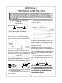
1
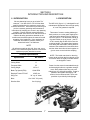
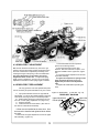
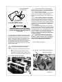
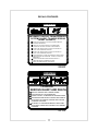
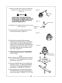
Mulch Pro and Finish Pro
MP-3132 and FP-3132
Operators Manual
Locke Turf Inc.
307 Highway 52E, Opp, Alabama 36467, (334) 493-1300
CONGRATULATIONS
You have invested in the best implement of its type on the market today.
The care you give you Locke Turf implement will greatly determine your
satisfaction with its performance and its service life. We urge a careful
study of this manual to provide you with a thorough understanding of
you new implement before operating, as well as suggestions for operation and maintenance.
If your manual should become lost or destroyed, Locke Turf will be glad
to provide you with a new copy. Order from Locke Turf, 307 Highway
52E, Opp, Alabama 36467.
As and Authorized Locke Turf dealer, we stock genuine Locke Turf parts
which are manufactured with the same precision and skill as our original
equipment. Our trained service personnel are well informed on methods required to service Locke Turf equipment, and are ready and able to
help you.
Should you require additional information or assistance, please contact
us.
YOUR AUTHORIZED
LOCKE TURF DEALER
BECAUSE LOCKE TURF MAINTAINS AN ONGOING PROGRAM
OF PRODUCT IMPROVEMENT, WE RESERVE THE RIGHT TO MAKE
IMPROVEMENTS IN DESIGN OR CHANGES IN SPECIFICATIONS
WITHOUT INCURRING ANY OBLIGATION TO INSTALL THEM
ON UNITS PREVIOUSLY SOLD.
BECAUSE OF THE POSSIBILITY THAT SOME PHOTOGRAPHS
IN THIS MANUAL WERE TAKEN OF PROTOTYPE MODELS,
PRODUCTION MODELS MAY VARY IN SOME DETAIL. IN ADDITION,
SOME PHOTOGRAPHS MAY SHOW SHIELDS REMOVED FOR PURPOSES OF CLARITY. NEVER OPERATE THIS IMPLEMENT WITHOUT
ALL SHIELDS IN PLACE.
MP-3132 and FP-3132
TABLE OF CONTENTS
SECTION
SECTION
Introduction
Dealer Preparation Check List
Safety Alert Symbols
Safety Precautions
Federal Laws and Regulations
I. INTRODUCTION & DESCRIPTION
Introduction
Description
II. PREPARATION FOR USE
Attaching To Tractor
III. OPERATING INSTRUCTIONS
General Safety
Cutting Height Adjustment
2
3
4
5
6
7
7
7
8
8
9
9
9
Operation
Transporting
IV. MAINTENANCE
Maintenance Check List
Lubrication
Spindle Belt Adjustment
Spindle Belt Replacement
Blade Replacement
Blade Spindle Service
Troubleshooting
Safety Decals
Torque Specifications
Spindle Service Instructions
10
10
12
12
13
13
14
15
15
16
18
19
RETAIL CUSTOMER’S RESPONSIBILITY
UNDER THE LOCKE TURF WARRANTY
It is the Retail Customer and/or Operator’s responsibility to read the Operator’s Manual, to
operate, lubricate, maintain and store the product in accordance with all instructions and
safety procedures. Failure of the operator to read the Operator’s Manual is a misuse of this
equipment.
It is the Retail Customer and/or Operator’s responsibility to inspect the product and to have
any part(s) repaired or replaced when continued operation would cause damage or excessive wear to other parts or cause a safety hazard.
It is the Retail Customer’s responsibility to deliver the product to the authorized Locke Turf
Dealer, from whom he purchased it, for service or replacement of defective parts that are
covered by warranty. Repairs to be submitted for warranty consideration must be made
with-in forty-five (45) days of failure.
It is the Retail Customer’s responsibility for any cost incurred by the Dealer for traveling to
or hauling of the product for the purpose of performing a warranty obligation or inspection.
1
INTRODUCTION
More than merely devices created for mowing grass, the excellence of design, construction and operation of Locke power mowers is unparalleled.
Introduced in 1928, tested and proven, Locke power mowers may be considered, in terms of today’s technology, the ultimate response to the need
for the highest degree of quality lawn care. These magnificent green machines are legendary and known throughout the world for generationspanning durability and unequalled performance in the precision cutting of
grass.
Locke power mowers are heavy-duty, precision instruments. No capricious model year or cosmetic style changes are instituted, although improvements are continually incorporated into all models. The most recent
evidence this is in the introduction of the new “Commercial Series”. Design
and manufacturing innovations make this the mower for the next century.
Whatever model of Locke power mower you have purchased you have our
assurance that, with proper care, you are the owner of a machine which
will provide many years of dependable service.
To extract the fullest possible value from the performance of your
Locke power mower we urge you to read this manual very carefully.
Should you find any of the instructions unclear, please contact your Locke
dealer or call the Locke Factory Service Department.
Phone: 334-493-1300
Fax: 334-493-1400
Locke Mowers: The Finest Cut….For The Finest Lawns
2
DEALER PREPARATION CHECK LIST
Tri-Deck Mulching and Finishing Mower
MP-3132 and FP-3132
BEFORE DELIVERING MACHINE- The following check list should be
completed. Use the Operator’s Manual as a guide.
1. Assembly completed.
2. Gearboxes filled with oil.
3. All fittings lubricated.
4. All shields in place and in good condition.
5. All fasteners torqued to specifications given in Torque Chart.
6. All decals in place and readable. (See decal page.)
7. Overall condition good (i.e. paint, welds)
8. Operators manual has been delivered to owner and he has been instructed on the
safe and proper use of the mower.
Dealer’s Signature______________________________________________________
Purchaser’s Signature___________________________________________________
THIS CHECKLIST IS TO REMAIN IN OWNER’S MANUAL
It is the responsibility of the dealer to complete the procedures listed
above before delivery of this implement to the customer.
3
Safety Alert Symbol
This Safety Alert Symbol means: “ATTENTION! BECOME
ALERT! YOUR SAFETY IS INVOLVED!”
This symbol is used to call attention to
safety precautions that should be followed
by the operator to avoid accidents. When
you see this symbol, carefully read the
message that follows and heed its advice.
Failure to comply with safety precautions
could result in death or serious bodily injury.
Safety Signs
Signal Words
The signal words DANGER, WARNING AND CAUTION are used on the equipment safety signs.
These words are intended to alert the viewer to the existence and the degree of hazard seriousness.
DANGER
This signal word indicates a potentially hazardous situation, which, if
not avoided, will result in death or serious injury.
WARNING
This signal word indicates a potentially hazardous situation, which, if
not avoided, will result in death or serious injury.
It may also be used to alert against unsafe practices.
CAUTION
This signal word indicates a potentially hazardous situation exist,
which, if not avoided, may result in minor or moderate injury.
It may also be used to alert against unsafe practices.
4
IMPORTANT SAFETY PRECAUTIONS
This symbol is used to call attention to safety
precautions that should be followed by
the operator to avoid accidents. When you
see this symbol, carefully read the message
that follows and heed its advice. Failure to
comply with safety precautions could result
in death or serious bodily injury.
In addition to the design and configuration of equipment, hazard control and accident prevention are dependent upon the awareness, concern, prudence and proper training of personnel in
the operation, transport, maintenance and storage of equipment. Lack of attention to safety
can result in accident, personal injury, reduction of efficiency and worst of all – loss of life.
Watch for safety hazards and correct deficiencies promptly. Use the following safety precautions as a general guide to safe operations when using this machine. Additional safety precautions are used throughout this manual for specific operation and maintenance procedures.
Read this manual and review the safety precautions often until you know the limitations.
1.
2.
3.
4.
5.
6.
7.
8.
9.
10.
11.
12.
13.
14.
15.
16.
17.
18.
Read the Operator’s Manual. Failure to read the Operator’s Manual is considered a misuse
of this equipment.
Become familiar with the entire machine’s controls and all the caution, warning and danger
decals affixed to the machine before attempting to start or operate.
Before starting or operating the machine, make a walking inspection and check for obvious
defects such as loose mounting bolts and damaged components. Correct any deficiency be
fore starting.
Do not allow children to operate the cutter. Do not allow adults to operate it without proper
instruction.
Do not carry passengers.
Keep the area of operation clear of all persons, particularly small children and pets. The
operator should cease mowing whenever anyone comes within the operating area.
Clear the work area of objects, which might be picked up and thrown.
Use a piece of cardboard or wood rather than hands to search for hydraulic leaks. Escaping
hydraulic oil under pressure can penetrate skin. If fluid is injected into the skin, it must be
surgically removed within a few hours by a doctor familiar with this form of injury or gangrene
may result.
Do not operate without all guards and shields in place and in good condition.
Lower implement to ground, stop tractor engine, apply parking brake and allow blades to
completely stop before leaving the tractor.
Keep hands and feet away from blades.
This cutter is not to be operated along highways or in any area where people may be present
unless all sides of the unit are enclosed by permanent bans, safety chains or other factory
approved safety shields that are in good repair.
Wear personal protective equipment such as, but not limited to, protection for eyes, ears, feet,
hands and head when operating or repairing the equipment. Do not wear loose clothing or
jewelry that may catch on equipment moving parts.
When performing adjustments or maintenance on the cutter, first lower it to the ground or block
it securely at a workable height.
Never stand between tractor and cutter while tractor is being backed to the cutter hitch.
Reduce speed when transporting cutter to avoid bouncing and momentary loss of steering.
Use tractor flashing warning lights, day or night, when transporting cutter on road or high ways
unless prohibited by law.
It is recommended that tractor be equipped with Rollover Protective System (ROPS) and seat
belt be used in all mowing operations.
5
IMPORTANT FEDERAL LAWS AND REGULATIONS* CONCERNING
EMPLOYERS, EMPLOYEES AND OPERATIONS.
*(This section is intended to explain in broad terms the concept and effect of the following federal laws and regulations. It is not intended as a legal interpretation of the laws and should not be considered as such.)
U.S. Public Law 91-596 (The Williams-Steiger Occupational and Health Act of 1970) OSHA
This Act Seeks:
“…to assure so far as possible every working man and woman in the nation safe and healthful
working conditions and to preserve our human resources…”
DUTIES
Sec. 5 (a) Each employer(1) shall furnish to each of his employees employment and a place of employment which are free
from recognized hazard that are causing or are likely to cause death or serious physical harm
to his employees;
(2) shall comply with occupational safety and health standards promulgated under this Act.
a. Each employee shall comply with occupational safety and health standards and all
rules, regulations and orders issued pursuant to this Act which are applicable to his
own actions and conduct.
OSHA Regulations
Current OSHA regulations state in part: “At the time of initial assignment and at least annually thereafter, the employer shall instruct every employee in the safe operation and servicing of all equipment with which the employee is
or will be involved.” These will include (but are not limited to) instructions to:
Keep all guards in place when the machine is in operations:
Permit no riders on equipment;
Stop engine, disconnect the power source and wait for all machine movement to stop before servicing,
adjusting, cleaning or unclogging the equipment, except where the machine must be running to be properly
serviced or maintained, in which case the employer shall instruct employees as to all steps and procedures
which are necessary to safely service or maintain the equipment.
Make sure everyone is clear of machinery before starting the engine, engaging power or operating the machine.
EMPLOYEE TRACTOR OPERATING INSTRUCTIONS:
1. Securely fasten your seat belt if the tractor has a ROPS
5. Watch where you are going especially at
row ends, on roads and around trees.
2. Where possible avoid operating the tractor near
Ditches, embankments and holes.
6. Do not permit others to ride.
7. Operate the tractor smoothly – jerky
turns starts or stops
3. Reduce speed when turning, crossing slopes and
on rough, slick or muddy surfaces
.
4. Stay off slopes too steep for safe operation
.
8. Hitch only to the drawbar and hitch
points recommended by tractor
manufacturers
9. When tractor is stopped, set brake
securely and use park lock if available
Child Labor Under 16 Years Old
Some regulations specify that no one under the age of 16 (sixteen) may operate power machinery. It is your responsibility to know what these regulations are in you own area or situation. (Refer to U.S. Dept, of Labor, Employment Standard Administration, Wage & Home Division, Child Labor Bulletin #102.)
6
SECTION I
INTRODUCTION AND DESCRIPTION
1-1 INTRODUCTION
1-2 DESCRIPTION
We are pleased to have you as a Locke Turf
customer. Your MP-3132 or FP-3132 has been
carefully designed to give maximum service with
minimum down time. This manual is provided to give
you the necessary operating and maintenance
instructions for keeping your mower in top operating
condition. Please read this manual thoroughly.
Understand what each control is for and how to use it.
Observe all safety precautions decaled on the
machine and noted throughout the manual for safe
operation of the implement. If any assistance or
additional information is needed, contact your
authorized Locke Turf distributor.
NOTE
All references made to right, left, front, rear, top or
bottom is as viewed facing the direction of travel with
implement properly attached to tractor.
Technical Specifications
Specification
11’
Transport Width
78”
Cutting Height
Blade Tip Speed (FPM)
Required Tractor PTO HP
Wing Flex
Belts
Driveline Size
Three sets of counter- rotating blades (per
deck) continue to cut the grass clippings several times before allowing the tiny pieces to
fall to the ground. This eliminates a build up
of grass residue on top of the turf. (the FP3132 is exactly like the MP-3132 minus the
mulching blades) The caster wheel arrangement along with the flexible, floating deck attachment, the standard front mounted rollers
and the under deck roller all work together to
give an even cut and minimize scalping.
NOTE: The inside rear wheel on the wing
mower decks and both the front wheels on the
rear mower deck are rigidly mounted and are
not designed to caste.
MP and FP
Cutting Width
The MP-3132, (figure 1-1), is designed for turf
maintenance applications where a high quality
of cut on turf grasses is required.
Power from the tractor is transmitted through
a telescoping driveline to a gearbox arrangement, which allows either wing unit to be
folded up to 30° while still operating. Power is
passed to the spindle housings by a Bsection, Kevlar reinforced belt. Drive train
protection is provided by belt slippage.
1/2" to 4”
15,000 FPM
45HP min.
30° up, 10° down
Cat. IV 80° CV (main)
Cat. III (wing)
7
SECTION II
PREPARATION FOR USE
Before operation, service all locations outlined in Section 4-2 “Lubrication” and remove transport lock
pins from mower decks as shown in Figure 3-4. Unpin inside wing tires and reposition into a trailing position and re-pin in place. Break in the mower in a static condition at half throttle for 30 minutes. Inspect
all belts for proper tension; check gearboxes for proper oil levels and check to make sure blade spindles
are not overheating.
2-1 ATTACHING TO TRACTOR
IMPORTANT
(540 RPM ONLY)
The minimum required PTO horsepower is 40 HP for the
MP-3132 and FP-3132.
D. Adjust tongue and clevis angle as necessary
to keep mower frame level with ground when attached
to drawbar. (Figure 2-2)
Figure 2-2 Tongue/Clevis Adjustment
WARNING
NEVER STAND BETWEEN TRACTOR AND
MOWER WHILE TRACTOR IS BEING
BACKED TO HITCH.
A. Adjust tractor drawbar length to dimension
shown in Figure 2-1. Incorrect drawbar length will
change angle of driveline causing possible damage to
constant velocity joint. See tractor operator’s manual for
drawbar adjustment procedure.
Figure 2-1 Tractor Drawbar Adjustment
540 RPM PTO
1-3/8" 6 SPLINE
14 IN
NOTE:
Offset drawbar
must be turned
down as shown.
It is important that the MP and FP are both operated in a level position. Leveling can be accomplished by adjusting the tractor draw bar height,
also by leveling the mower frame by use of the
adjustable jack stand.
If after properly leveling the mower frame the
draw bar height is less than 8”, a standard pull pin
may be too long. To prevent turf damage in unIf after turning the offset draw bar downward, there is
even terrain, the standard pin should be replaced
less than 7” ground clearance, it should be replaced with with a 1” x 5” Grade 5 bolt with locknut securely
a straight draw bar or the unit cannot be properly leveled. tightened.
IMPORTANT
E. Connect hydraulic hose to tractor remote
PTO ADAPTERS SHOULD NOT BE USED WITH quick couplers. (See tractor dealer if furnished couANY LOCKE TURF EQUIPMENT. FAILURE TO plers are not correct for your particular tractor.) Make
FOLLOW THESE INSTRUCTIONS WILL CAUSE sure hydraulic line is not twisted or kinked.
DRIVELINE FAILURE AND POSSIBLE TRACTOR
DAMAGE.
WARNING
B. Attach jack stand to frame of cutter. Extend jack
stand to support weight of frame.
C. Connect clevis hitch to tractor drawbar using a 1
inch (25 mm) diameter approved pin with lynch pin retainer or equivalent.
USE A PIECE OF CARDBOARD OR WOOD
RATHER THAN HANDS AND WEAR EYE PROTECTION WHEN SEARCHING FOR HYDRAULIC LEAKS. ESCAPING HYDRAULIC OIL UNDER PRESSURE CAN PENETRATE SKIN. IF
OIL IS REMOVED WITHING A FEW HOURS OR
GANGRENE MAY RESULT.
8
F. Route control chain to convenient location
and fasten to tractor. Be sure excess slack is removed from the chain to avoid entanglement with
tractor tires or other moving parts. Make sure
latch locking pins are in the stored positions so
that latches can be released by pulling the chain.
G. Attach driveline to tractor. Pull on each driveline
section to be sure that yoke locks into place.
H. Securely attach safety chain to tractor.
(Refer to Figures 3-3 and 3-4)
Figure 2-3
Control Chain
SECTION III
OPERATING INSTRUCTIONS
3-1 GENERAL
SAFETY
Only qualified people familiar with this operator’s
manual and tractor operator’s manual should operate this machine. Operator should wear hardhat,
safety glasses and safety shoes. The operator
should read, understand and practice all safety
messages shown on the caution, warning and
danger decals affixed to the mower to avoid serious injury or death. It is recommended that tractors be equipped with Rollover Protective System
(ROPS) and a seat belt must be used. Before
beginning operation, clear work area of any objects that may be picked up and thrown, check for
ditches, stumps, holes or other obstacles that
could upset tractor or damage mower. Always
lower mower to ground and allow blades to come
to a complete stop, having set parking brake and
turn off the tractor’s engine before leaving the tractor operator’s seat.
NOTE: Before initial operation the MP-3132 and
FP-3132 should be connected to the tractor for a
30-minute “run in” cycle. During the “run in”
phase, the tractor should be operated at only half
throttle. The “run in” cycle is complete, ALL
belts should be inspected for proper tension and
if adjustments are necessary, refer to Maintenance Section.
A.
Raise the mower off ground enough to remove
caster.
WARNING
THE MOWER CAN FALL FROM HYDRAULIC
SYSTEM FAILURE. TO AVOID SERIOUS INJURY OR DEATH, SECURELY SUPPORT
MOWER BEFORE WORKING UNDERNEATH.
B.
Remove pin securing caster stem to caster arm.
Remove caster stem from caster arm.
C. Place amount of spacers on caster stem to give
desired cutting height. With no spacers on the bottom, a 3/4" cutting height is given. (Figure 3-1)
D. Reinstall caster stem into caster arm. Place remaining spacers on caster stem above caster arm
and install pin to retain.
E. Repeat operation for all caster wheels. Make certain all wheels are adjusted to the same height.
Figure 3-1
Caster Wheel
Spacers
3-2 CUTTING HEIGHT ADJUSTMENT
The mower should be operated at the highest position that will give desired cutting results. This will
help prevent blades from striking the ground, reducing blade wear and unnecessary strain on the
machine. Cutting too much material may reduce
mulching action and leave visible clippings on the
9
3-3 OPERATION
A.
B.
Perform BEFORE EACH USE maintenance list
in paragraph 4-1.
Start tractor. Lower cutter decks until they are
supported by caster wheels and hydraulic cylinders are fully extended to allow mechanical
float to operate. (Figure 3-2)
Figure 3-2 Make Sure Cylinders Are Fully Extended To
Allow Decks To Float
Wing Cylinder Lug
Spacing
DANGER
STAY CLEAR OF ROTATING DRIVELINE.
DO NOT OPERATE WITHOUT DRIVELINE
SHIELDS IN PLACE AND IN GOOD CONDITION. FAILURE TO HEED THESE WARNINGS MAY RESULT IN PERSONAL INJURY
OR DEATH.
When mowing across slopes, yawing or skewing may occur as the mower slips sideways,
which may cause streaking. In this case, mowing up and down slopes should be done to
eliminate skewing.
3-4 TRANSPORTING
IMPORTANT- Before folding for transport, disengage the PTO and wait for
blades to stop. Pull the latch chain to
allow complete folding, then release the
chain to lock decks in the raised position. These locks also serve the purpose of limiting the upward flex of the
cutter decks during operation. FOLDING THE DECKS WITH THE PTO’S ENGAGED WILL DESTROY THE DRIVE
LINES!
Install pins into the transport lock positions.
(Figures 3-3 & 3-4) When implement is transported on road or highway, day or night, use
tractor flashing warning lights unless prohibited
by law. The slow moving vehicle (SMV) sign
must be visible from the rear by approaching
vehicles.
Figure 3-3 Center Unit Transport Latch
DANGER
STAND CLEAR OF ROTATING CUTTER
BLADES UNTIL ALL MOTION HAS
STOPPED. TO AVOID ACCIDENTAL FALL
AND POSSIBLE INJURY FROM CUTTER,
IT IS RECOMMENDED THAT TRACTOR BE
EQUIPPED WITH ROLLOVER PROTECTIVE SYSTEM AND THAT A SEAT BELT
BE USED FOR ALL OPERATIONS
C. With tractor at idle speed, engage PTO drive.
Advance throttle to 540 PTO rpm.
D. Place tractor in low gear and begin cutting.
Tractor forward speed should be controlled by
gear selection, not engine speed. For maximum
cutting efficiency, forward speed should allow
mower to maintain a constant maximum blade
speed.
If tractor engine or cutter stalls, do not slip tractor clutch to allow engine to retain speed, as this
will exert undue strain on the implement drive
train. When stalling occurs, disengage PTO
drive, move to a cut area, set tractor throttle to
idle, then re-engage PTO drive.
10
NOTE: The mower deck transport locking
pins provided on the win g sections (Figure
3-4) MUST be removed BEFORE operation.
Failure to remove these locking pins will
result in front caster wheel damage, turf
damage and unacceptable mowing performance.
TIPS ON MOWING WITH A MULCHER
The Locke Turf Mulch Pro is a turf maintenance mower with counter rotating blade sets designed to do a superior job of mulching grass clippings. To obtain the maximum effectiveness from your Mulch Pro the tips listed below should be followed:
Mow often – In general, mulching operations require more frequent mowing than
would conventional mowing procedures.
Watch your speed – Normal conditions will allow a speed of up to approximately 5
mph, but thick, heavy, damp conditions will require reduced ground speed.
Mow at 540 RPM to keep tip speed at its maximum.
Mow with a clean mower – Avoid grassy build-up under the deck.
Mow with sharp blades – A sharp blade cuts cleaner.
Wet grass will decrease distribution effectiveness and increase horsepower requirements. Leaves, on the other hand, may be more effectively mulched when they are
slightly damp.
Mow at higher cutting heights – Remove and mulch no more than 2” – 2-1/2” of
grass length with each mowing. (Experts recommend not cutting off more than 1/3
of the grass blade length at any given time.)
Mow twice, at different height settings, (high, then low), if grass is extra tall.
Remember that horsepower requirements will vary with the mowing conditions such
as type and height of turf grass, moisture content, whether the terrain is flat or hilly,
etc.
The ideal cutting height may be different from other types of mowing equipment you
have used. Initially you should adjust your MP at least 1/2" higher than other types
of equipment. Use a trial and error method to determine if the MP should be adjusted lower. Generally it is
best to begin high and work
you way lower.
11
SECTION IV
MAINTENANCE
4-1 MAINTENANCE CHECK LIST
4-2 LUBRICATIONS
NOTE
Perform scheduled maintenance as outlined below.
Lower implement to ground, turn off tractor and set
parking brake before doing maintenance inspections or
work. All bolts should be torqued as indicated in torque
chart unless otherwise indicated.
The multi-purpose grease referenced in this section
is a NLGI Grade 2 type grease. Figure 4-2 shows the
necessary position for servicing wing drivelines.
BEFORE EACH USE
WARNING
THE MOWER CAN FALL FROM HYDRAULIC SYSTEM FAILURE. TO
AVOID SERIOUS INJURY OR DEATH,
SECURELY SUPPORT MOWER BEFORE WORKING UNDERNEATH.
BEFORE EACH USE
1. Check tractor tire air pressure. Refer to tractor
operator’s manual. Mower transport tire pressure
should be 22 psi; deck tire pressure should be 50
psi.
2. Check blades and spindles to be sure that no
foreign objects such as wire or steel strapping bands
are wrapped around them.
3. Check blade bolts for tightness. Tighten bottom blade bolts to 76 ft./lbs, top mulching blade
bolts to 45 ft./lbs.
4. Inspect blades for wear. Replace if necessary
per paragraph 4-5. Use only genuine Locke Turf replacement parts. If it is necessary to sharpen the
blades, remove the blades from the spindles before
sharpening. DO NOT sharpen blades while still attached to mower.
5. Make certain all shields are in place and in
good condition. Repair or replace any missing or damaged shields.
6. Inspect wheel(s) for wear, damage or foreign
objects. Repair or replace any missing or damaged
shields.
7. Perform BEFORE EACH USE lubrication per
paragraph 4-2.
8. During operation, listen for abnormal sounds,
which might indicate loose parts, damaged bearings, or
other damage. Correct any deficiency before continuing
operation.
AFTER EACH USE
1. Clean all debris from machine especially underside of deck, underneath belt shield and off safety
decals. Replace any missing or illegible decals.
2. Inspect cutter for worn or damaged components. Repair or replace before next use. Any replacement components installed during repair shall include
the components’ current safety decals specified by the
manufacturer to be affixed to the component.
3. Store cutter in a dry place.
1.
Drive line Universal Joints – Apply multipurpose grease with grease gun.
2.
Drive line Guard – Apply 2-3 shots of multipurpose grease with grease gun to plastic fitting.
3.
Wheels – Apply multi-purpose grease with
grease gun.
4.
Caster Pivot – Apply multi-purpose grease with
grease gun.
5.
Constant Velocity (CV) Joint – Position CV
joint as straight as possible to be sure grease will
penetrate to ball joint. Lubricate the central body
with a minimum of 30 shots of grease every 8
hours. Lubricate telescoping members with 10
shots every 8 hours and every 40 hours pull the two
sections apart, apply thin coat of multi-purpose
grease to outside of inner (male) section and reassemble.
20 HOURS
6.
Deck Drivelines – Disconnect PTO driveline,
pull the two sections apart, apply thin coat of multipurpose grease to outside of inner (male) section. Reassemble sections and install. Pull each section to be
sure driveline and shields are securely connected.
Make certain PTO shielding is in good condition.
40 HOURS
7.
Gear boxes (5) – Add EW80W-90 gear oil, if
necessary, to bring oil level to check plug or dip stick
mark.
8.
Wing Pivots – Apply 5 shots of multi-purpose
grease with grease gun.
9.
Cylinder Rod Lugs – Apply 5 shots of multipurpose grease with grease gun.
10. Deck Pivots – Apply 5 shots of multi-purpose
grease with grease gun.
END OF SEASON
11. Transport Wheel Bearings – Pack transport
wheel bearings with grease at end of each mowing season.
40 HOURS
Check belt for proper tension. Refer to paragraph 4-3.
12
4-3 SPINDLE BELT ADJUSTMENT
Belt tensions should be checked every 40 hours to get
maximum life from drive belts and best performance form
the cutter. Belt tension is adjusted by increasing or decreasing the length of the spring on the moveable idlers.
For proper belt tension on the mower, the spring
lengths should be set at 2-7/8”. To adjust the spring
length, loosen or tighten the 1/2" hex nuts on the spring
adjustment rod until the correct spring length is reached.
4-4 SPINDLE BELT REPLACEMENT
1. Place both belts into their respective
grooves on the driving sheave.
2. Work the lower belt over the other
sheaves. After the lower belt is in place, complete the installation of the upper belt. (Figure
4-3)
3. Connect the upper adjustment rod and the
upper idler assembly.
4. Tighten the compression springs on the
upper and lower drives to 2-7/8” long.
Tighten the jam nuts on the adjustment
rods.
5. Replace all shields before operating machine.
Use only genuine Locke Turf replacements parts.
It is not necessary to replace both belts if only one is worn.
A. Flip up black latches and remove right and left
side shields. To remove the outside shields on the wing
cutter decks, the wings must be in the folded position.
B. Relieve spring tension by loosening the two 1/2"
hex nuts on each spring adjustment rod. (Figure 4-2)
C. Remove old belts.
D. Install new belts as shown below. (Also refer to
the decal on underside of belt shield)
1.Belts must be installed at the same time. One
belt cannot be installed and tightened down before
the other.
2.Disconnect the upper adjustment rod from the upper
idler assembly. (Figure 4-2)
13
Figure 4-2 Spindle Belts
(Lower Belt - Fig. 4-3)
UPPER BELT DIAGRAM
Upper Adjustment
Rod & Spring
2-7/8" Driving Sheave
At Gearbox
Upper Idler
Assembly
Lower Adjustment
Rod & Spring
2-7/8"
Driving Sheave
At Gearbox
4-5 BLADE REPLACEMENT
CAUTION
WEAR HEAVY WORK GLOVES TO PROTECT
HANDS FROM SHARP EDGES. WHEN TURNING
BLADES, BE AWARE OF OPPOSITE BLADE APPROACHING.
A complete spare set of blades comes with the cutter.
The lower blades are pinned on the frame and the upper blades are stored in the tool box. (Figure 4-4)
Always replace all (4) blades on an assembly to retain
balance. In addition to replacing blades when they
become worn and dull, they should also be replaced if
the uplift angle on the trailing side of the blade becomes worn off. As the angle wears down, the mulching action deteriorates.
D. Remove the four 3/8” x 1” capscrews and
Belleville washers from the upper mulching assembly.
Remove mulching assembly. The blade bushing will
come off with the mulching assembly.
E.
Remove the 3/8” –24 UNF x 7/8” Gr. 8 blade
bolt and nut for each blade. Inspect the blade nut
shoulder and the blade bolts for wear. Replace if necessary.
F.
When installing new blades on the mulching
assembly, make sure that two blades are installed on
the top side of the assembly 180° from each other and
two on the bottom side of the assembly. The blades
must mount on the rotation “pads” for proper operation.
Assemble the (4) new blades to the blade holder using
the blade nuts, bolts and flatwashers. Tighten the
bolts to 45 ft./lbs.
G. Insert the blade bushing in the center of the
mulching assembly so that the bushing flange is on the
top side of the assembly. Slide the mulching assembly
and flanged bushing over the spindle shaft and secure
mulching assembly to the upper blade carrier using the
(4) 3/8” – 16 UNC x 3/4" Gr. 5 bolts and Belleville
washers. Torque all (4) mulching assembly attaching bolts to 31 ft./lbs
H. Install the blade washer over the spindle
shaft. Install the bottom blade and torque the 1/2" –
20 UNF Gr. 8 bolt to 76 ft./lbs. Note: The concave
side of the Belleville washer must be toward the
blades. Do not substitute with a flatwasher.
Figure 4-5 Blade Arrangement
A.
Raise the cutter using the tractor hydraulic
system and use transport locks before changing
blades.
B. Turn off tractor, set parking brake and remove
key.
C. Remove bolt and Belleville washer securing
bottom blade to spindle. Remove blade. Shaft
washer will come off with the blade. (Figure 4-5)
3/8” - 24 UNF x 7/8” Gr. 8 Blade Bolt & Blade Nut
Upper Blade Assembly
Figure 4-4 Spare Blades and Tool Box
Rotation Pad
14
4-6 BLADE SPINDLE SERVICE
If shaft bearings or other parts require replacement, it is recommended that a Locke Turf dealer or other qualified person service the blade spindle. If blade spindles must be disassembled, a special wrench kit must be
used to prevent damage to the assembly. This Wrench Kit (Part Number 50026073), including a sheave
wrench, carrier wrench and complete instructions, is available form Locke Turf. (Figure 4-6) Refer to “Blade
Spindle Service” at the rear of this manual.
Figure 4-6
Sheave Wrench
Carrier Wrench
4-7 TROUBLESHOOTING
Troubleshooting procedures are listed in Table 4-1 below. If the problem cannot be solved or replacement parts
are necessary, contact your authorized Locke Turf dealer. Please have ready your machine name, model number, serial number, purchase date and exact cause or description of the problem.
PROBLEM
PROBABLE CAUSE
REMEDY
Uneven Cut
Cutter not level side to side
or front to rear.
See SECTION III
Belt slipping.
Adjust belt per paragraph 4-3
Worn or bent blade(s).
Possible build-up of
material under cutter.
Replace blade(s).
Clean Cutter
Cutter not level.
See SECTION III
Worn blades.
Replace blades.
Belt slipping.
Loose components.
Adjust belt per paragraph 43.
Check all bolts for tightness.
Low oil in gearbox.
Check oil per paragraph 4-2.
Rapid Blade Wear
(cutting edge)
Blade contacting ground.
Adjust cutting height to
eliminate ground contact.
Rapid Blade Wear
Cutter not being
Operated at rated PTO
speed.
Set tractor throttle for proper
PTO speed.
Cutter Vibrating
Cutter not being operated at
rated PTO speed.
Set tractor throttle for proper
PTO speed
Blade(s) bent.
Replace blades.
Foreign object wrapped
around spindle or blade.
Remove object.
Streaking or Windrowing
Noisy Cutter
Use lower gear
15
SAFETY DECALS
To promote safe operation, Locke Turf supplies safety decals on all products manufactured. Damage can occur to safety decals either through shipment, use or reconditioning, so Locke Turf will, upon request, provide safety decals for any of our products in the field at no charge. Contact your authorized Locke Turf dealer for more
information.
WARNING
94878
ALL AIR MUST BE PURGED
FROM HYDRAULIC SYSTEM
BEFORE ATTEMPTING TO
RAISE OR LOWER THIS
MACHINE. REFER TO
OPERATOR'S MANUAL FOR
FURTHER DETAILS.
TO AVOID SERIOUS INJURY OR DEATH:
CAUTION
LOCK WINGS UP FOR TRANSPORT
INSTALL TRANSPORT LOCK PINS
READ OPERATOR'S MANUAL FOR
INSTRUCTION
83343
83343
DANGER
CAUTION
KEEP AWAY - ROTATING BLADES
SERIOUS INJURY OR DEATH CAN RESULT FROM
THROWN OBJECTS OR BLADE CONTACT.
ALL AIR MUST BE PURGED
FROM HYDRAULIC SYSTEM
BEFORE ATTEMPTING TO
RAISE OR LOWER THIS
MACHINE. REFER TO
OPERATOR'S MANUAL FOR
FURTHER DETAILS.
DO NOT STAND ON OR NEAR MACHINE WHEN IN OPERATION
DO NOT OPERATE WITH DEFLECTORS OR GUARDS REMOVED
ROPS (ROLLOVER PROTECTIVE SYSTEM) AND SEAT BELT EQUIPPED TRACTOR IS RECOMMENDED FOR OPERATOR USE IN ALL MOWING OPERATIONS
82619
WARNING
ROTATING DRIVE PARTS
BENEATH
94878
ENTANGLEMENT WITH ROTATING
DRIVE PARTS CAN CAUSE INJURY OR
DEATH
DO NOT OPERATE WITHOUT THIS
AND ALL OTHER SHIELDS IN PLACE
AND IN GOOD CONDITION
94878
WARNING
50012615
DANGER
WARNING
TO AVOID
SERIOUS INJURY OR DEATH,
READ OPERATOR'S MANUAL BEFORE
OPERATING & FOLLOW ALL PRECAUTIONS.
(CONTACT DEALER FOR MANUALS)
KEEP CHIELDS AND GUARDS IN PLACE.
KEEP CLEAR OF DRIVES AND BELTS.
LOWER IMPLEMENT, STOP ENGINE AND
REMOVE KEY BEFORE DISMOUNTING.
ROTARY CUTTERS MAY
DISCHARGE OBJECTS AT
HIGH SPEEDS, WHICH
COULD RESULT IN SERIOUS
INJURY TO BY-STANDERS
OR PASSERS-BY.
NO RIDERS. DO NOT OPERATE MOWER IN
VICINITY OF OTHER PERSONS.
DO NOT OPERATE CUTTER IN VICINITY OF
OTHER PERSONS.
KNOW HOW TO STOP TRACTOR AND
EQUIPMENT QUICKLY IN AN EMERGENCY.
SECURELY SUPPORT MOWER & REMOVE
KEY BEFORE WORKING UNDERNEATH.
KEEP AWAY!
KEEP ENCLOSED SIDES, PERMANENT
BANDS, BELTING, HIGHWAY CHAINS OR
OTHER FACTORY APPROVED DISCHARGE
SHIELDS IN PLACE AND IN GOOD REPAIR.
CLEAR MOWING AREA OF DEBRIS
SHIELD MISSING FROM THIS AREA
TO AVOID SERIOUS INJURY OR DEATH
DO NOT OPERATE WITHOUT THIS AND
ALL OTHER SHIELDS IN PLACE AND IN
GOOD CONDITION 50012616
82618
82618
ALLOW NO CHILDREN OR UNQUALIFIED
PERSONS TO OPERATE EQUIPMENT.
BE CAREFUL ON UNEVEN TERRAIN.
DECREASE SPEED WHEN TURNING.
DO NOT OPERATE MOWER IN TRANSPORT POSITION.
50012616
WARNING
CAUTION
THIS IMPLEMENT IS DESIGNED TO OPERATE
AT 540 RPM MAXIMUM TRACTOR PTO SPEED.
82617
TO AVOID SERIOUS INJURY OR DEATH,
DO NOT OPERATE MOWER WITHOUT DISCHARGE
SHIELD OR DEFLECTOR IN PLACE AND GOOD REPAIR.
ALL DRIVE LINE SHIELDS MUST BE KEPT IN
60873
PLACE.
83056
60873
83056
16
DECALS CONTINUED
WARNING
IMPLEMENT CAN FALL FROM HYDRAULIC
SYSTEM FAILURE. TO AVOID SERIOUS
INJURY OR DEATH,
BLOCK UP OR SECURELY SUPPORT IMPLEMENT BEFORE
WORKING UNDERNEATH.
PURGE ALL AIR FROM HYDRAULIC SYSTEM BEFORE
ATTEMPTING TO RAISE OR LOWER THIS IMPLEMENT.
DO NOT USE HAND OR SKIN TO CHECK FOR HYDRAULIC
LEAKS. USE CARDBOARD OR WOOD.
DO NOT USE HAND OR SKIN TO CHECK FOR HYDRAULIC
LEAKS. USE CARDBOARD OR WOOD.
HIGH PRESSURE OIL LEAKS CAN PENETRATE SKIN CAUSING
SERIOUS INJURY AND GANGRENE. CONSULT A PHYSICIAN
IMMEDIATELY.
LOWER THE IMPLEMENT AND RELEASE HYDRAULIC
PRESSURE BEFORE LOOSENING FITTINGS.
REFER TO OWNERS MANUAL FOR DETAILS.
82683
WARNING
TO AVOID
SERIOUS INJURY AND DEATH,
DO NOT OPERATE WITH WINGS RAISED.
LOCK WINGS UP FOR TRANSPORT.
STAND CLEAR IF LOWERING OR RAISING WINGS.
DECREASE SPEED WHEN TURNING, BE CAREFUL
ON SLOPES OR UNEVEN TERRAIN WITH WINGS
IN RAISED POSITION.
BE ALERT TO OVERHEAD OBSTRUCTIONS AND
ELECTRICAL WIRES WITH WINGS IN THE RAISED
POSITION.
83105
17
TORQUE SPECIFICATIONS
Proper torque for American fasteners used on Locke Turf
equipment. Recommended Torque in Foot Pounds
AMERICAN
Bolt Head Markings
WRENCH
SIZE (IN.) “A”
BOLT DIAMETER
(IN.) “B” AND
SAE
GRADE 2
SAE
GRADE 5
SAE
GRADE 8
THREAD SIZE
SAE Grade 2
(No Dashes)
SAE Grade 5
(3 Dashes)
D
Wrench
Size "A"
"
lt
Bo er "B
t
e
iam
SAE Grade 8
(6 Dashes)
t
"
1/4 –20 UNC
6 (7)
8 (11)
12 (16)
7/16
1/4 –28 UNF
6 (8)
10 (13)
14 (18)
1/2
5/16 – 18 UNC
11 (15)
17 (23)
25 (33)
1/2
5/16 – 24 UNF
13 (17)
19 (26)
27 (37)
9/16
3/8 – 16 UNC
20 (27)
31 (42)
44 (60)
9/16
3/8 – 24 UNF
23 (31)
35 (47)
49 (66)
5/8
7/16 – 14 UNC
32 (43)
49 (66)
70 (95)
5/8
7/16 – 20 UNF
36 (49)
55 (75)
78 (106)
3/4
1/2 – 13 UNC
49 (66)
76 (103)
106 (144)
3/4
1/2 – 20 UNF
55 (75)
85 (115)
120 (163)
7/8
9/16 – 12 UNC
70 (95)
109 (148)
153 (207)
7/8
9/16 – 18 UNF
79 (107)
122 (165)
172 (233)
15/16
5/8 – 11 UNC
97 (131)
150 (203)
212 (287)
15/16
5/8 – 18 UNF
110 (149)
170 (230)
240 (325)
1-1/8
3/4 – 10 UNC
144 (195)
266 (360)
376 (509)
1-1/8
3/4 –16 UNF
192 (260)
297 (402)
420 (569)
1-5/16
7/8 – 9 UNC
166 (225)
430 (583)
606 (821)
1-5/16
7/8 – 14 UNF
184 (249)
474 (642)
668 (905)
1-1/2
1 –8 UNC
250 (339)
644 (873)
909 (1232)
1-1/2
1 – 12 UNF
274 (371)
705 (955)
995 (1348)
1-1/2
1 – 14 UNF
280 (379)
721 (977)
1019 (1381)
1-11/16
1-1/8 – 7 UNC
354 (480)
795 (1077)
1288 (1745)
1-11/16
1-1/8 – 12 UNF
397 (538)
890 (1206)
1444 (1957)
1-7/8
1-1/4 – 7 UNC
500 (678)
1120 (1518)
1817 (2462)
1-7/8
1-1/4 – 12 UNF
553 (749)
1241 (1682)
2013 (2728)
2-1/16
1-3/8 – 6 UNC
655 (887)
1470 (1992)
2382 (3228)
2-1/16
1-3/8 – 12 UNF
746 (1011)
1672 (2266)
2712 (1992)
2-1/4
1-1/2 – 6 UNC
870 (1179)
1950 (2642)
3161 (4283)
2-1/4
1-1/2 – 12 UNF
979 (1327)
2194 (2973)
3557 (4820)
Proper torque for American fasteners used on Locke Turf equipment.
Recommended Torque in Foot Pounds (Newton Meters). *
METRIC
"
lt
Bo ter "B
e
m
Dia
Wrench
Size "A"
7/16
8.8
Numbers appearing on bolt heads
Indicate ASTM class.
*Use 75% of the specified torque value
for plated fasteners. Use 85% of the
specified torque values for lubricated
fasteners.
WRENCH
SIZE
(mm) “A”
BOLT
DIA.
(mm) “B”
ASTM
4.6
ASTM
8.8
ASTM
9.8
ASTM
10.9
8
5
1.8 (2.4)
5.1 (6.9)
6.5 (8.8)
10
6
3 (4)
8.7 (12)
11.1 (15)
27 (37)
13
8
7.3 (10)
21.1 (29)
16
10
14.5 (20)
42 (57)
53 (72)
18
12
25 (34)
74 (100)
73 (99)
93 (126)
21
14
40 (54)
118 (160)
116 (157)
148 (201)
24
16
62 (84)
167 (226)
181 (245)
230 (312)
30
20
122 (165)
325 (440)
33
22
36
24
41
27
46
30
18
449 (608)
443 (600)
611 (828)
211 (286)
563 (763)
778 (1054)
821 (1112)
1138 (1542)
418 (566)
1119 (1516)
1547 (2096)
LOCKE TURF
BLADE SPINDLE SERVICE
BLADE SPINDLE DISASSEMBLY
Figure 2
1. Using safety gloves, hold the lower blade and remove the 1/2" x 1-3/4” capscrew, Belleville washer,
blade and shaft washer.
Shaft Bushing
2. Remove the (4) 3/8” capscrews holding the upper
disc assembly to the blade carrier. Lift the disc assembly and shaft bushing off the spindle shaft.
3. Support the spindle housing in a press with the
blade carrier turned up. Press the inner shaft top
bearing and upper sheave out. (Figure 3)
Shaft Washer
4. Remove the 5/8” locknut from the inner shaft and
press the sheave off.
5. Remove the woodruff key and top bearing.
CAUTION
Lower Blade
Clockwise
Belleville
Washer
1/2 x 1-3/4”
Capscrew
USE SAFETY EYE PROTECTION
WHEN USING HAMMER AND
PUNCH TO PREVENT FLYING
PARTICLES FROM INJURING
EYES.
6. Using a blunt punch: unstake sheave from upper end of
outer shaft and unstake blade carrier from lower end of
outer shaft. (Use care so as not to damage the threads.)
(Figure 4)
Figure 4
19
(4) 3/8 x 3/4”
Capscrews
7.
Using two 3/8” x 3/4" UNC threads Grade 8
capscrews, bolt the carrier wrench to the blade
carrier. (Wrench Kit 50026073) (Figure 5)
Figure 5
Blade Carrier
Wrench
8.
Put the spindle in the upright position and place
the blade carrier wrench in a vise and secure it.
(Figure 5)
Vise
THE CARRIER WRENCH AND SHEAVE
WRENCH REFERRED TO IN THESE INSTRUCTIONS ARE CONTAINED IN
WRENCH KIT 50026073.
9.
Place the sheave wrench on the sheave, aligning the two studs with the two holes in the
sheave. (Wrench Kit 5002073) THESE
THREADS ARE LEFT HANDED. TO LOOSEN,
TURN CLOCKWISE. Remove sheave. (Figure
6)
10. Remove spindle from vise and place the housing in a press with the blade carrier turned down.
Press the outer shaft, lower bearing and blade
carrier out.
Figure 6
Sheave
Wrench
11. Place the outer shaft in a vise and remove the
blade carrier. THESE THREADS ARE LEFT
HANDED. TO LOOSEN, TURN CLOCKWISE. (Figure 7) You may have to heat shaft Figure 7
to loosen; if so, remove inner bearing first.
12. Press the bearing off the shaft.
13. Using a punch on a flat surface, drive the top
outer bearing from the housing.
20
3/8” x 3/4”
UNC Threads
Grade 8
Vise
Blade Carrier
BLADE SPINDLE ASSEMBLY
1. Press the outer bearing in the housing
until the bearing bottoms out. (Figure 8)
Figure 8
2. Press the lower outer bearing on the
shaft until it bottom out. (Figure 9)
Top Outer
Bearing
Housing
Figure 9
3. Place the outer shaft and lower bearing through the hub into the top outer
bearing. Press together until both
outer bearing races bottom out on
housing and shaft. (Figure 10)
Shaft
Lower Outer
Bearing
Figure 10
4. Press the inner bearing into the top of
the outer shaft. (Figure 10)
5. Thread the blade carrier and the
sheave on the outer shaft. (Figure 11)
Figure 11
6. Attach the blade carrier wrench to the
blade carrier (Figure 5). Put the spindle in the upright position and place
the blade carrier wrench in a vise and
secure it.
Sheave
Blade
Carrier
7. Use the sheave wrench (Figure 6).
Turn counterclockwise and tighten
sheave to 200 ft.lbs.
Figure 12
8. Remove spindle from vise. Place the
sheave wrench in the vise and secure
it. (Figure 12) Place the spindle
sheave on the sheave wrench and
tighten the blade carrier to 200 ft.lbs.
Sheave Wrench
21
9. Remove the blade carrier wrench and restake the
blade carrier into the notch of the outer shaft.
(Figure 13)
Figure 13
CAUTION
USE SAFETY EYE PROTECTION
WHEN USING HAMMER AND PUNCH
TO PREVENT FLYING PARTICLES
FROM INJURING EYES.
Figure 14
Inner Shaft
10. Restake the drive sheave into the notch of the outer
shaft. (Figure 13)
Bottom Inner
Bearing
11. Press the bottom inner bearing on the lower
end of the inner shaft. (Figure 14)
Figure 15
12. Place the inner shaft and lower bearing
through the outer shaft and top inner bearing.
Press together until the top bearing has bottomed out on the shaft and the bottom bearing
has bottomed out in the outer shaft. The top
and bottom bearings will be recessed in the
outer shaft. (Figure 15)
13. Install the Woodruff key, sheave, flatwasher
and nut onto the inner shaft. TORQUE NUT
TO 76 FT.LBS.
NOTE
Before installing upper blade assembly, install the
three 1/2" x 1-1/2” carriage bolts into the spindle housing. (Figure 16)
14. Place the shaft bushing on the spindle shaft.
Using the (4) 3/8” x ¾” capscrews and Belleville washer, bolt the blade assembly to the
blade carriers. TORQUE TO 32 FT.LBS.
15 Using safety gloves, install the shaft washer,
lower blade, Belleville washer and blade bolt
onto the inner shaft. TORQUE TO 76 FT.LBS.
22
Figure 16
1/2” x 1-1/2”
Carriage Bolts
Locke Turf Inc.
307 Highway 52E, Opp, Alabama 36467, (334) 493-1300