1
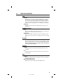
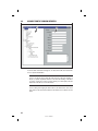
PRINTER’S INSTRUCTIONS:
INSTR,RA-2400/DVS-2400,REF GUIDE - LINEAR P/N: 217473 C - INK: BLACK - MATERIAL: 20 LB. MEAD BOND - SIZE: 8.500” X 5.500” - SCALE: 1-1 - FOLDING: ALBUM FOLD - BINDING: SADDLE STITCH
RA-2400
REMOTE ACCESS
SOFTWARE
Reference Manual for Programming the
DVS-1200, DVS-2400, DUAL-824 & DVS-2408
Supervised Wireless Security Systems
WRITER’S NOTE: This publication could contain technical inaccuracies or typographical errors.
Changes are periodically made to the information herein; these changes will be incorporated in
new editions of the publication. Linear may make improvements and/or changes in the product(s)
and/or software described in this publication at any time.
MS-DOS®, Windows™, WindowsNT™, Windows95™, Windows98™, WindowsME™,
WindowsXP™ and Windows2000™, and are registered trademarks of Microsoft Corporation.
Pentium® is a registered trademark of Intel Corporation.
IBM® is a registered trademark of International Business Machines Corporation.
FOR TECHNICAL ASSISTANCE CALL:
Linear Technical Services: 1-800-421-1587
217473 C - IMAGE 1
TABLE OF CONTENTS
1. GENERAL INFORMATION . . . . . . . . . . . . . . . . . . . . . . . . . . . . . . . . . . . . . . . . . . . . . . . . . . . . 1
1.1
SOFTWARE DESCRIPTION . . . . . . . . . . . . . . . . . . . . . . . . . . . . . . . . . . . . . . . . . 1
1.2
SYSTEM REQUIREMENTS. . . . . . . . . . . . . . . . . . . . . . . . . . . . . . . . . . . . . . . . . . 2
1.3
PROGRAMMING OUTLINE . . . . . . . . . . . . . . . . . . . . . . . . . . . . . . . . . . . . . . . . . . 3
1.4
PROGRAM INSTALLATION . . . . . . . . . . . . . . . . . . . . . . . . . . . . . . . . . . . . . . . . . . 4
1.5
TESTING THE MODEM . . . . . . . . . . . . . . . . . . . . . . . . . . . . . . . . . . . . . . . . . . . . . 5
2. OVERVIEW . . . . . . . . . . . . . . . . . . . . . . . . . . . . . . . . . . . . . . . . . . . . . . . . . . . . . . . . . . . . . . . . 6
2.1
STARTING THE PROGRAM . . . . . . . . . . . . . . . . . . . . . . . . . . . . . . . . . . . . . . . . . 7
2.2
NEW WINDOW. . . . . . . . . . . . . . . . . . . . . . . . . . . . . . . . . . . . . . . . . . . . . . . . . . . . 7
2.3
MENU BAR. . . . . . . . . . . . . . . . . . . . . . . . . . . . . . . . . . . . . . . . . . . . . . . . . . . . . . . 8
2.4
ACCOUNT PROFILE WINDOW OVERVIEW . . . . . . . . . . . . . . . . . . . . . . . . . . . . 10
3. COMMUNICATIONS SETUP. . . . . . . . . . . . . . . . . . . . . . . . . . . . . . . . . . . . . . . . . . . . . . . . . . 11
3.1
COM PORT . . . . . . . . . . . . . . . . . . . . . . . . . . . . . . . . . . . . . . . . . . . . . . . . . . . . . 12
3.2
SPEAKER. . . . . . . . . . . . . . . . . . . . . . . . . . . . . . . . . . . . . . . . . . . . . . . . . . . . . . . 12
3.3
CONNECTION OPTIONS . . . . . . . . . . . . . . . . . . . . . . . . . . . . . . . . . . . . . . . . . . 13
3.4
MODEM INITIALIZATION STRING . . . . . . . . . . . . . . . . . . . . . . . . . . . . . . . . . . . 14
4. CREATING A CUSTOM ACCOUNT PROFILE . . . . . . . . . . . . . . . . . . . . . . . . . . . . . . . . . . . . 15
4.1
NEW WINDOW. . . . . . . . . . . . . . . . . . . . . . . . . . . . . . . . . . . . . . . . . . . . . . . . . . . 16
4.2
CUSTOMER INFORMATION . . . . . . . . . . . . . . . . . . . . . . . . . . . . . . . . . . . . . . . . 17
4.3
CONSOLE ACCESS CODES. . . . . . . . . . . . . . . . . . . . . . . . . . . . . . . . . . . . . . . . 18
4.4
CONSOLE ARM/DISARM . . . . . . . . . . . . . . . . . . . . . . . . . . . . . . . . . . . . . . . . . . 19
4.5
CONSOLE ENTRY/EXIT . . . . . . . . . . . . . . . . . . . . . . . . . . . . . . . . . . . . . . . . . . . 20
4.6
CONSOLE ALARMS . . . . . . . . . . . . . . . . . . . . . . . . . . . . . . . . . . . . . . . . . . . . . . 21
4.7
CONSOLE HOME-AUTOMATION OUTPUT . . . . . . . . . . . . . . . . . . . . . . . . . . . . 22
4.8
CONSOLE AUDIO . . . . . . . . . . . . . . . . . . . . . . . . . . . . . . . . . . . . . . . . . . . . . . . . 23
4.9
SENSORS . . . . . . . . . . . . . . . . . . . . . . . . . . . . . . . . . . . . . . . . . . . . . . . . . . . . . . 24
4.10
COMMUNICATOR MAIN . . . . . . . . . . . . . . . . . . . . . . . . . . . . . . . . . . . . . . . . . . . 26
4.11
COMMUNICATOR ROUTING AND NUMBERS. . . . . . . . . . . . . . . . . . . . . . . . . . 27
4.12
COMMUNICATOR ENABLED REPORTS . . . . . . . . . . . . . . . . . . . . . . . . . . . . . . 28
4.13
COMMUNICATOR 4 BY 2 FORMAT . . . . . . . . . . . . . . . . . . . . . . . . . . . . . . . . . . 29
4.13.1 4 BY 2 POINT-TO-POINT ALARM CODES . . . . . . . . . . . . . . . . . . . . . . . . . . . . . 30
4.13.2 4 BY 2 POINT-TO-POINT TROUBLE CODES . . . . . . . . . . . . . . . . . . . . . . . . . . . 31
4.13.3 4 BY 2 POINT-TO-POINT ARMING (CLOSING) CODES . . . . . . . . . . . . . . . . . . 32
4.13.4 4 BY 2 POINT-TO-POINT DISARMING (OPENING) CODES . . . . . . . . . . . . . . . 33
4.13.5 4 BY 2 CONSOLE ALARM CODES . . . . . . . . . . . . . . . . . . . . . . . . . . . . . . . . . . . 34
4.13.6 4 BY 2 GENERAL ALARM CODES . . . . . . . . . . . . . . . . . . . . . . . . . . . . . . . . . . . 35
4.14
ADEMCO CONTACT-ID REPORT CODES . . . . . . . . . . . . . . . . . . . . . . . . . . . . . 36
5. SENDING AND RECEIVING CONSOLE DATA . . . . . . . . . . . . . . . . . . . . . . . . . . . . . . . . . . . 37
5.1
ACCESSING THE SEND/RECEIVE WINDOW . . . . . . . . . . . . . . . . . . . . . . . . . . 38
5.2
CHOOSING AN ACCOUNT PROFILE . . . . . . . . . . . . . . . . . . . . . . . . . . . . . . . . . 39
5.3
CONNECTING TO A CONSOLE . . . . . . . . . . . . . . . . . . . . . . . . . . . . . . . . . . . . . 40
5.4
SENDING DATA . . . . . . . . . . . . . . . . . . . . . . . . . . . . . . . . . . . . . . . . . . . . . . . . . . 42
5.5
RECEIVING DATA . . . . . . . . . . . . . . . . . . . . . . . . . . . . . . . . . . . . . . . . . . . . . . . . 43
5.6
CHANGING THE CONSOLE’S MODE. . . . . . . . . . . . . . . . . . . . . . . . . . . . . . . . . 44
5.7
DISCONNECTING FROM THE CONSOLE . . . . . . . . . . . . . . . . . . . . . . . . . . . . . 45
5.8
CLOSING RA-2400 . . . . . . . . . . . . . . . . . . . . . . . . . . . . . . . . . . . . . . . . . . . . . . . 46
217473 C - IMAGE 2
1.1
SOFTWARE DESCRIPTION
What is the RA-2400 Remote Access Software?
The RA-2400 Remote Access software is a communications program designed
to work with Linear’s DVS Supervised Wireless Security Systems and other
Linear products. The software runs on an IBM PC or compatible computer
and connects to the console through the standard telephone network, or to the
Console directly, with the computer’s modem. This 32-bit software runs under all
Windows operating systems.
RA-2400 sets the options for: Console access codes, exit/entry delays, alarm,
audio, and sensors; communicator telephone numbers, call routing, formats,
reporting codes, account numbers, and other options.
The RA-2400 software has a large help file that can be accessed at any time by
selecting “Contents” from the “Help” menu or by pressing the F1 key.
How does RA-2400 connect to a DVS Console?
Remote Access communicates with the Console over the same phone line the
Console uses to send communicator reports. Remote Access can also connect
to the Console without a telephone line by directly connecting the Computer
modem’s LINE jack to the Console’s T & R Terminals using a telephone cord.
With a telephone line connection (remote connection), a special dialing
procedure is used. First, Remote Access dials the phone number specified for
the Console. Remote Access waits long enough for the phone to ring two or
three times, then hangs up. Next, Remote Access waits, then dials again. This
second call is answered on the first ring by the Console.
With a direct connection (local cable connection), Remote Access prompts the
user to place the Console in Test Mode and press the Console’s EMERGENCY
button to establish the connection.
Once the connection is made, the Console will check if its remote access
password matches the calling software’s password. If the passwords match,
access is granted.
Do I have to be connected to a Console to make programming changes?
Since Remote Access knows the programming structure, you can modify an Account
Profile without being connected to a Console. This means you can set all of the
values for a specific Console configuration and then connect to a unit and send all of
the values that you have set. This is referred to as off-line Console configuration.
How do I change Console settings while on-line?
While on-line with the Console, make any changes to the Account Profile then
send the data to change the Console.
Can I make a template with the typical settings for all of my accounts?
Programming “templates” can be created to speed up programming multiple
Consoles. Common settings, such as the Central Station telephone number,
communicator format, Console and communicator configurations which are
shared by all of your accounts can be stored in an Account Profile and used as
a template. That template file can be used as a basis for creating each customer
Account Profile file. See “Using Profile Copies” in the Help contents for more
information on creating a template.
How do I add and remove the program’s password?
A password can be set to restrict the RA-2400 to authorized users only. To add
a password, select “Change Password...” from the “Options” menu. Enter the
password in the “New Password” field. Verify it by entering the password again
in “Re-type New Password” and click OK. To remove the password, enter your
password in “Old Password”, don’t enter anything on the “New Password” and
“Re-type New Password” fields and press OK.
1
217473 C - IMAGE 3
1.2
SYSTEM REQUIREMENTS
Minimum System Requirements:
IBM compatible 486 personal computer with 8 Mb RAM
Windows 95/98/NT/ME/XP/2000 operating systems
VGA monitor
Name brand modem that is capable of 300 baud (BELL 103
compatible)
Hard disk drive with 10 Mb available space for the software
plus 18K available space for each Account Profile file.
CD drive
Recommended System:
Pentium or better based personal computer with 16 Mb RAM
or more
Windows 95/98/NT/ME/XP/2000 operating systems
SVGA video card
Microsoft compatible mouse
Name brand modem that is capable of 300 baud (BELL 103
compatible)
Large hard disk drive (1000 Account Profiles use about 20
Mb)
CD drive
Compatible Systems Note:
The software described in this manual supports the programming of a variety of
models of Linear’s Wireless Security Systems. References in these instructions are
focused on the Model DVS-2400.
The programming differences for the other models supported by this software are:
DVS-1200: This model is identical to the DVS-2400 with the limitation of supporting
only 12 sensors. Only the first 12 sensors can be programmed in Sections 4.9,
4.13.1, and 4.13.2.
DVS-2408/DUAL-824: This model programs the same as the DVS-2400 with the
addition of supporting 8 hardwired loops. Hardwired loop programming is described
in Section 4.9.
PERS-2400: This model is not a Security System, but a Personal Emergency
Reporting System. Refer to the RA-2400/PERS-2400 Programming Reference
Guide P/N: 217163 for details on programming this model.
2
217473 C - IMAGE 4
1.3
PROGRAMMING OUTLINE
Use the following programming outline to guide you through the steps
required to set up the RA-2400 software and program a DVS-2400
Console. Many of the programming options available in the RA-2400
program can be left in their default settings, and do not need to be
changed for most installations.
1. SETUP RA-2400 SOFTWARE
✦ Install the software on your computer (Section 1.4).
✦ Test your computer’s modem (Section 1.5).
✦ Start the RA-2400 program (Section 2.1).
✦ Set the Communications Setup options (Section 3).
2. CUSTOMIZE AN ACCOUNT PROFILE
✦ Open a new Account Profile (Section 4.1).
✦ Enter customer information (Section 4.2).
✦ Set the Console’s access codes (Section 4.3).
✦ Set the Console’s arm/disarm options (Section 4.4).
✦ Set the Console’s exit/entry delays (Section 4.5).
✦ Set the Console’s alarm options (Section 4.6).
✦ Set the Console’s home-automation options (Section 4.7).
✦ Set the Console’s audio options (Section 4.8).
✦ Enable the Console’s communicator and choose a communicator
format (Section 4.10).
✦ Choose the communicator’s account number, telephone numbers,
and trouble report routing (Section 4.11).
✦ Set the communicator reporting options (Section 4.12).
✦ Set the communicator format reporting options (Section 4.13 or
4.14).
3. PROGRAM THE CONSOLE WITH THE ACCOUNT PROFILE
✦ Choose an Account Profile (Section 5.2).
✦ Connect to the Console (Section 5.3).
✦ Send the data to the Console (Section 5.4).
✦ Receive the data from the Console (Section 5.5).
✦ Change the Console’s Mode (Section 5.6).
✦ Disconnect from the Console (Section 5.7).
IMPORTANT:
AFTER ANY PROGRAMMING CHANGES ARE MADE TO A
CONSOLE, PERFORM THOROUGH TESTING TO VERIFY THAT THE
CONSOLE OPERATES AS INTENDED.
3
217473 C - IMAGE 5
1.4
PROGRAM INSTALLATION
The RA-2400 Remote Access Program software is supplied on a CDROM. The installation program will create a directory on your hard disk
drive. Be sure that you have at least 10 megabytes free on the hard disk
for the program and any Account Profile files that you create.
To Install the Remote Access Program:
✦ The first step is to close all other running programs.
✦ Place the Remote Access CD into your computer CD drive.
✦ The installation process should start automatically. If the CD does
not auto run, use Windows Explorer to find RASETUP.EXE on the
CD. Double-click on RASETUP.EXE and the install program will
start.
✦ Click the Next button to install the Remote Access software.
Follow the on-screen instructions as the setup program creates
the directory and copies the program files onto your hard disk. A
Remote Access icon will be created on your desktop screen.
✦ If you are performing a reinstallation, or an update, you will be
prompted to uninstall RA-2400 first. After the uninstall is completed,
browse to the appropriate drive letter for your CD drive and doubleclick on RASETUP.EXE. Then follow the on-screen steps to install
the Remote Access software.
☞ NOTE: If Windows asks whether to replace existing .DLL files, first
answer NO. If RA-2400 fails to run, re-install RA-2400 and answer
YES to replace existing .DLL files.
✦ Remove the CD and store it in a safe place.
To Remove the Remote Access Program:
✦ Press START, SETTINGS, CONTROL PANEL. Double-click on
ADD/REMOVE PROGRAMS.
✦ Select Linear RA-2400 and click ADD/REMOVE or CHANGE/
REMOVE button depending on your Windows Operating system.
4
217473 C - IMAGE 6
1.5
TESTING THE MODEM
Before you run the Remote Access Program, be sure that the computer
is running correctly and that the modem is installed and working
properly.
To Test the Modem:
Windows Control Panel can be used to test the modem and determine
what COM port it is connected to.
✦ Press START, SETTINGS, CONTROL PANEL. Double-click on
MODEMS.
✦ Verify that a modem is shown in the Modem Properties window.
✦ Click on the DIAGNOSTICS tab. The modem installed with the
COM port highlighted should be shown.
✦ Note the COM port information. It is used when setting COM port in
the Communications Setup window (see Section 3.1).
✦ Test the modem by pressing the MORE INFO... button. IF THE
MODEM IS CONNECTED AND WORKING PROPERLY, THE
“MORE INFO” WINDOW WILL DISPLAY DETAILED MODEM
INFORMATION. If the modem is not working properly, Windows will
notify you.
5
217473 C - IMAGE 7
2.
OVERVIEW
2.1
STARTING THE PROGRAM . . . . . . . . . . . . . . . . . . . . . . . . .
7
2.2
NEW WINDOW . . . . . . . . . . . . . . . . . . . . . . . . . . . . . . . .
7
2.3
MENU BAR . . . . . . . . . . . . . . . . . . . . . . . . . . . . . . . . . .
8
2.4
ACCOUNT PROFILE WINDOW OVERVIEW . . . . . . . . . . . . . . . . . 10
☞ NOTE: Experienced computer or PC users should find that entering
data and navigating around the RA-2400 program dialog boxes
is similar to most other Windows programs. New users, or users
unfamiliar with running Windows applications, should refer to the
Windows help file for details on using Windows.
6
217473 C - IMAGE 8
2.1
STARTING THE PROGRAM
To Run the Program:
✦ Press START, point to PROGRAMS, RA2400 and click on RA2400.
2.2
NEW WINDOW
PURPOSE:
To select an Account Profile template for the type of unit being
programmed.
USER RESPONSE:
✦ Select DVS-2400/2408 (with the correct Console firmware version
number).
✦ Press OK.
The RA-2400 program window will appear with a starter template called
DVS-2400/2408 Vx.x-1 showing in the workspace. This file can be
stored later, under any name, using SAVE AS... in the FILE menu (see
Section 2.3).
7
217473 C - IMAGE 9
2.3
MENU BAR
PURPOSE:
To provide access to each of the programs sub-menus.
The sub-menus that can be accessed from this menu are:
File
NEW
To select an Account Profile template for the type of unit being
programmed.
OPEN
Loads a saved Account Profile into the RA-2400 workspace. Multiple Account Profiles can be open at the same time in the RA-2400
workspace. They can be arranged in the workspace using the
Window menu on the menu bar, or by dragging them around
manually.
CLOSE
Closes the active Account Profile. If there were any changes to the
file, Windows will ask if you want to save the changes.
SAVE
Saves the active Account Profile to the hard drive, overwriting the
existing file.
SAVE AS...
Saves the active Account Profile while giving the option to change
the name or location of the file.
PRINT...
Opens the PRINT window to allow printing of the active Account
Profile. Resulting printout is the entire content of the Account
Profile file in text format.
PRINT PREVIEW
Shows what will be printed on the screen with options to zoom in
or print the document.
RECENT FILE LIST
Shows the last four file names (with paths) that were opened in
RA-2400. Clicking on a file opens it.
EXIT
Closes the RA-2400 program. If any open Account Profiles have
changed, Windows will ask if you want to save them.
8
217473 C - IMAGE 10
2.3
MENU BAR (CONTINUED)
VIEW
TOOL BAR
When checked, the tool bar is displayed. NOTE: The tool bar can
be turned into a re-sizable floating tool bar window by dragging
it out of its docked location at the top of the workspace. The tool
bar accesses many of the popular menu items. Hover the mouse
pointer over the tool bar button to see a description of the button.
STATUS BAR
When checked, the status bar is displayed at the bottom of the
workspace.
COMMUNICATIONS
SETUP...
Opens the Communication Setup window. Used for setting up the
modem and connection type (local or remote).
SEND/RECEIVE...
Opens the Send/Receive window. Used for connecting to a Console to send or receive data or to change the Console’s operating
mode.
OPTIONS
CHANGE PASSWORD
Opens the Change Password window. Used for changing or removing the password required to enter the RA-2400 program. THIS IS
NOT THE REMOTE ACCESS PASSWORD USED TO CONNECT
TO THE DVS-2400 CONSOLE.
WINDOW
CASCADE
Arranges all open Account Profile windows layered across the
workspace.
TILE
Arranges all open Account Profile windows next to each other in
the workspace.
HELP
CONTENTS
Opens the help Contents search window. Used for accessing the
RA-2400’s built-in help file.
ABOUT RA-2400 REMOTE ACCESS
Displays the version number of the RA-2400 software.
9
217473 C - IMAGE 11
2.4
ACCOUNT PROFILE WINDOW OVERVIEW
MENU TREE
EDIT AREA
PURPOSE:
To enter data and make changes to an Account Profile and customize
it for a specific installation.
MENU TREE
Used for selecting the various data entry fields in the Account Profile. Clicking on
the plus (+) symbols expands the branches of the menu tree. Clicking on the minus
(-) symbols collapses the menu tree branch. Clicking on an item displays the data
entry fields in the edit area or other information.
EDIT AREA
Used for adding and changing the data in the Account Profile. Click on the check
boxes, buttons, and enter text and numbers in the data areas to modify the Account
Profile.
10
217473 C - IMAGE 12
3.
COMMUNICATIONS SETUP
3.1
COM PORT . . . . . . . . . . . . . . . . . . . . . . . . . . . . . . . . . . 12
3.2
SPEAKER . . . . . . . . . . . . . . . . . . . . . . . . . . . . . . . . . . . 12
3.3
CONNECTION OPTIONS . . . . . . . . . . . . . . . . . . . . . . . . . . . 13
3.4
MODEM INITIALIZATION STRING . . . . . . . . . . . . . . . . . . . . . . 14
PURPOSE:
The communications setup window sets the COM port for the modem,
the modem’s speaker characteristics, type of connection (local or
remote), dialing method (tone or pulse), and modem initialization
string.
USER RESPONSE:
✦ From the COMMUNICATIONS menu, select SETUP... to view the
Communications Setup window.
✦ See Sections 3.1 - 3.4 and make any changes as required.
✦ After making any changes to the Communication Setup window,
click OK to accept the changes and close the window.
11
217473 C - IMAGE 13
3.1
COM PORT
PURPOSE:
To select which communications (COM) port the modem is connected
to.
USER RESPONSE:
✦ Click on the COM port number (1, 2, 3, or 4) that the modem is
connected to.
☞ NOTE: See the TESTING THE MODEM Section (1.5) of this
manual for determining the proper COM port number.
3.2
SPEAKER
PURPOSE:
To set how the modem’s speaker functions before and during
communications.
USER RESPONSE:
✦ Select OFF to silence the modem’s speaker at all times.
✦ Select CARRIER to hear the modem connect and have the speaker
silenced when the RA-2400 is connected to the DVS-2400 Console.
✦ Select ON to hear the modem connect and hear the RA-2400
communicate with the DVS-2400 Console (for testing only).
12
217473 C - IMAGE 14
3.3
CONNECTION OPTIONS
PURPOSE:
To choose how the modem will connect to the DVS-2400 Console.
Remote Dialing dials a telephone number with the method chosen (tone
or pulse) to connect with the Console over a standard telephone line.
Local Cable Connection does not dial a telephone number, but
communicates with the Console wired directly to the modem.
USER RESPONSE:
✦ Select REMOTE DIALING if the Console is going to be accessed over
the telephone line.
✦ Select TONE or PULSE depending on the requirements for your
telephone system. NOTE: This only affects Remote Dialing.
✦ Select LOCAL CABLE CONNECTION if the Console’s T & R terminals
are connected directly to the modem’s LINE jack.
LOCAL CABLE CONNECTION
CONSOLE
MODEM
MODEM'S LINE JACK TO CONSOLE'S T & R TERMINALS
13
217473 C - IMAGE 15
3.4
MODEM INITIALIZATION STRING
PURPOSE:
Used to choose whether the default or a custom initialization “string” is
sent to configure the modem (a “string” is a series of characters that
are commands for the modem). Modem’s use initialization strings to
setup their speed, data type, and other options. The RA-2400 sends the
initialization string to the modem before using the modem to connect to
the DVS-2400.
☞ NOTE: There are hundreds of models of modems available,
each with unique characteristics. Instead of using the default
modem string, some modems may perform better with a custom
initialization string.
USER RESPONSE:
✦ Leave USE DEFAULT INITIALIZATION STRING option selected unless
you are having trouble connecting with your modem.
✦ IF YOU ARE HAVING TROUBLE CONNECTING WITH YOUR
MODEM, and it tests OK with the Windows modem test diagnostics
(see Section 1.5), try using a custom initialization string. Various
model modems have different requirements for initialization strings.
Refer to your modem’s manual for the required commands to place
the modem in 300 BAUD BELL 103 configuration. Two examples
are “&F1&N1” and “N0S37=1”. If the initalization string is incorrect,
the RA-2400 will display “ERROR WRITING INITIALIZATION
STRING”.
☞ NOTE: When entering a custom initialization string, don’t enter the
“AT” command. The RA-2400 program will do this automatically.
14
217473 C - IMAGE 16
4.
CREATING A CUSTOM ACCOUNT PROFILE
4.1
NEW WINDOW . . . . . . . . . . . . . . . . . . . . . . . . . . . . . . . . 16
4.2
CUSTOMER INFORMATION . . . . . . . . . . . . . . . . . . . . . . . . . 17
4.3
CONSOLE ACCESS CODES . . . . . . . . . . . . . . . . . . . . . . . . . 18
4.4
CONSOLE ARM/DISARM. . . . . . . . . . . . . . . . . . . . . . . . . . . 19
4.5
CONSOLE ENTRY/EXIT . . . . . . . . . . . . . . . . . . . . . . . . . . . 20
4.6
CONSOLE ALARMS . . . . . . . . . . . . . . . . . . . . . . . . . . . . . 21
4.7
CONSOLE HOME-AUTOMATION OUTPUT . . . . . . . . . . . . . . . . . 22
4.8
CONSOLE AUDIO . . . . . . . . . . . . . . . . . . . . . . . . . . . . . . 23
4.9
SENSORS . . . . . . . . . . . . . . . . . . . . . . . . . . . . . . . . . . . 24
4.10
COMMUNICATOR MAIN . . . . . . . . . . . . . . . . . . . . . . . . . . . 26
4.11
COMMUNICATOR ROUTING AND NUMBERS . . . . . . . . . . . . . . . 27
4.12
COMMUNICATOR ENABLED REPORTS . . . . . . . . . . . . . . . . . . 28
4.13
COMMUNICATOR 4 BY 2 FORMAT . . . . . . . . . . . . . . . . . . . . . 29
4.13.1 4 BY 2 POINT-TO-POINT ALARM CODES . . . . . . . . . . . . . . . . . . 30
4.13.2 4 BY 2 POINT-TO-POINT TROUBLE CODES . . . . . . . . . . . . . . . . 31
4.13.3 4 BY 2 POINT-TO-POINT ARMING (CLOSING) CODES. . . . . . . . . . . 32
4.13.4 4 BY 2 POINT-TO-POINT DISARMING (OPENING) CODES . . . . . . . . 33
4.13.5 CONSOLE ALARM CODES . . . . . . . . . . . . . . . . . . . . . . . . . 34
4.13.6 4 BY 2 GENERAL ALARM CODES . . . . . . . . . . . . . . . . . . . . . 35
4.14
ADEMCO CONTACT-ID REPORT CODES . . . . . . . . . . . . . . . . . . 36
Each installation requires an Account Profile. While many items are the
same in different Consoles reporting to the same Central Station, some
items (account number, customer information, & sensor information)
are unique for each installation.
A custom Account Profile is created by editing the DVS-2400 Account
Profile template included with the RA-2400 software. The customized
profile should then be saved with a unique name for the account and
then sent to the DVS-2400 Console.
To provide a clean start. Close any open Account Profiles on the
workspace.
15
217473 C - IMAGE 17
4.1
NEW WINDOW
PURPOSE:
To select an Account Profile template for the type of unit being
programmed.
USER RESPONSE:
NEW
✦ Click on NEW icon on tool bar or select NEW from the FILE menu.
✦ Select DVS-2400/2408 (with the correct Console firmware version
number).
✦ Click OK.
The new Account Profile will appear as a starter template called
DVS-2400/2408 Vx.x-1 (or -2, -3, etc.) in the workspace.
16
217473 C - IMAGE 18
4.2
CUSTOMER INFORMATION
PURPOSE:
For entering customer information specific to the installation for the
Account Profile.
USER RESPONSE:
CUSTOMER
☞ NOTE: All fields are optional and do not have to be filled in. This
information is not sent to the Console.
✦ Enter a CUSTOMER ID for the installation.
✦ Enter the customers name in the NAME field.
✦ Enter the customers address in ADDRESS fields 1, 2, & 3.
✦ Enter the customers telephone number(s) in PHONE fields 1 & 2.
✦ Enter the number of the telephone line that the Console is
connected to in the CONSOLE PHONE field. This field will show as the
telephone number for the account in the Send/Receive window.
☞ NOTE: DO NOT enter any dashes or spaces into the telephone
number fields. Enter numbers only.
✦ Enter any special information about the customer in the NOTES field.
17
217473 C - IMAGE 19
4.3
CONSOLE ACCESS CODES
PURPOSE:
To install a Master Access Code and up to 5 Restricted Access Codes,
a Duress Code, and a Page Alert Code.
CODE DEFINITIONS:
MASTER ACCESS CODE
✦ Allows arming and disarming the Console. Allows access to all programming
options.
RESTRICTED ACCESS CODE
✦ Allows arming and disarming the Console. Allows entering and editing
Restricted Access Codes.
DURESS ACCESS CODE
✦ Allows all options of a Restricted Access Code and causes the Console to
report the duress code to the Central Station if programmed to report.
PAGE ALERT CODE
✦ Allows all options of a Restricted Access Code and causes the Console
to dial the supervisory number (see Section 4.11, Communicator Routing
and Numbers).
USER RESPONSE:
ACCESS CODES
✦ MASTER: When power is first applied to the Console the Master Access Code
is “1234”. Enter any combination of 1 to 5 digits (3 to 5 digits recommended)
for the Master Access Code.
✦ RESTRICTED: Enter any combination of 1 to 5 digits (3 to 5 digits
recommended) for Restricted Access Codes 1-5.
✦ DURESS: Enter any combination of 1 to 5 digits (3 to 5 digits recommended)
for the Duress Code. The Duress Code should be 2 or more digits different
than any other user code to help minimize accidental activation.
✦ PAGE ALERT: Enter any combination of 1 to 5 digits (3 to 5 digits
recommended) for the Page Alert Code.
18
217473 C - IMAGE 20
4.4
CONSOLE ARM/DISARM
PURPOSE:
To select which modes any remote arm/disarm transmitters will switch
to. Also for selection of five arm/disarm options.
USER RESPONSE:
ARM/DISARM
✦ TOGGLE-ARM TO: Select either HOME or AWAY to choose the mode that any
remote arm/disarm transmitters will arm the Console to.
✦ TOGGLE-DISARM TO: Select either OFF or CHIME to choose the mode that
any remote arm/disarm transmitters will disarm the Console to.
✦ CHIRP ON REMOTE ARM/DISARM: When arming with the portable remote
control, if this box is checked the Console will “chirp” once when armed,
twice when disarmed, and three times when arming with sensors bypassed.
Un-check this box to silence the “chirps”.
✦ AUTO-BYPASS: If this box is unchecked, the user must manually bypass
any open sensors when the system is armed. If arming is attempted with
open sensors, the Console will sound five two-tone beeps and will not
arm. Arming to the same mode again within five seconds will bypass any
open sensors and arm the Console. Check this box and the Console will
automatically bypass any open sensors when the system is armed.
✦ BYPASS-RESTORAL: Bypassed sensors are ignored by the Console and
cannot cause an alarm. If this box is checked, the Console will automatically
restore (remove the bypass from) any bypassed sensor when the sensor
closes. After it’s restored, the sensor is ready to cause an alarm the next
time it is opened. Un-check this box to not automatically restore sensors
that close.
✦ ALLOW QUICK-ARM: If this box is checked, it allows the Console to be armed
by holding down a mode key for two seconds. Un-check this box and an
access code must be entered before pressing the mode buttons.
✦ HOME AUTOMATION OUTPUT ACTIVE WHILE ARMED: If this box is checked,
the Console’s Automation Output will activate when the system is armed.
Un-check this box to disable this feature.
19
217473 C - IMAGE 21
4.5
CONSOLE ENTRY/EXIT
PURPOSE:
To select delay times and other options for the Console’s exit and entry
delays.
USER RESPONSE:
ENTRY/EXIT
✦ ENTRY DELAY: To change the entry delay, enter a delay time from
20 to 255 seconds.
✦ EXIT DELAY: To change the exit delay, enter a delay time from 20
to 255 seconds.
✦ BEEP DURING ENTRY DELAY: With this box checked, beeps will sound
during the entry delay. Un-check this box to silence the beeps
during the entry delay.
✦ BEEP DURING EXIT DELAY: With this box checked, beeps will sound
during the exit delay. Un-check this box to silence the beeps during
the exit delay.
✦ HOME-AUTOMATION OUTPUT ACTIVE DURING ENTRY/EXIT: With this box
checked, the home-automation output will be active during the
entry/exit delay. Un-check this box to disable this feature.
20
217473 C - IMAGE 22
4.6
CONSOLE ALARMS
PURPOSE:
For setting the way the burglary, emergency and fire sirens work.
Also sets the options for the home-automation output during and after
alarms.
USER RESPONSE:
ALARMS
✦ BURGLARY ALARM: Select SILENT to disable the burglary siren or
select SIREN FOR SET TIME for a timed siren after activation. With
timed siren selected, enter the length of time (from 1 to 30 minutes)
for the burglary siren to run.
✦ EMERGENCY ALARM: Select SILENT to disable the emergency siren
or select SIREN FOR SET TIME for a timed siren after activation. With
timed siren selected, enter the length of time (from 1 to 30 minutes)
for the emergency siren to run.
✦ FIRE ALARM: Enter the length of time (from 1 to 30 minutes) for the
fire siren to run in the FIRE ALARM SIREN TIME area.
✦ HOME-AUTOMATION OUTPUT DURING SIREN TIME: Select NONE, FLASH,
or ACTIVE from the drop-down menu to choose the way the
home-automation output functions while the siren is running.
✦ HOME-AUTOMATION OUTPUT FLASHES DURING/AFTER ALARM: With this
box checked, the home-automation output will flash during and after
an alarm until the Console is disarmed.
☞ NOTE: The home-automation output will activate steady if the
above option is set to ACTIVE.
21
217473 C - IMAGE 23
4.7
CONSOLE HOME-AUTOMATION OUTPUT
PURPOSE:
For setting the way the home-automation output functions.
USER RESPONSE:
HOME AUTOMATION-OUTPUT
✦ WHEN TRIGGERED: Select TOGGLES to cause the home-automation
output to switch between on & off with each activation. Select
ACTIVE FOR SET DURATION for a timed home-automation output and
enter the length of time 1-2500 (in seconds) for the output to
activate.
✦ WHEN ACTIVE: Select OPEN to have the home-automation minus
terminal float when the output is active. Select SHORTED TO COMMON
to have the home-automation minus terminal switch to common
ground when the output is active.
✦ AUDIBLE BELL WHEN TRIGGERED: With this box checked, the Console
will sound a “bing” when the home-automation output is activated.
Un-check this box to have the home-automation output activate
silently.
22
217473 C - IMAGE 24
4.8
CONSOLE AUDIO
PURPOSE:
To select how the Voice Board operates. NOTE: The Model VB-2 (for
2-way audio) or VB-3 Voice Board must be installed to use these
options. Selects the audio mode for monitoring with the Console’s
microphone and communicating through the Console’s speaker to the
subscriber. Controls the human voice prompts from the Voice Board.
With 2-way Audio enabled, after the Central Station operator
acknowledges the communicators report, the Console will stop its siren
and switch to the selected audio mode for 90 seconds.
USER RESPONSE:
AUDIO
✦ Click the arrow to show a list of settings for Two-way Audio and
select the desired mode.
NONE: Audio Board will not report as an audio account to the Central Station. No
audio monitoring will occur.
LISTEN-ONLY: The operator will be able to hear sound from the Console but will
not be able to talk through the Console’s speaker. Pressing “9” on a telephone
connected to the line disconnects the call (press any key but “9” to extend the time
90 seconds).
TWO-WAY MANUAL: The operator will be able to hear sound from the Console
and will be able to talk through the Console’s speaker. The operator can switch
from listen to talk by pressing “1”, or switch from talk to listen by pressing “3” on a
telephone connected to the line. Pressing “9” disconnects the call (press any key but
“9” to extend the time 90 seconds).
TWO-WAY DUPLEX: The operator will be able to hear sound from the Console and
will be able to talk through the Console’s speaker. The audio board will listen until the
operator speaks, then the voice activation will switch the voice board to talk as long
as the operator speaks. The operator can still switch from listen to talk manually by
pressing “1”, or switch from talk to listen by pressing “3” on a telephone connected
to the line (with increased volume). Pressing “8” returns to two-way duplex. Pressing
“9” disconnects the call. Press any key but “9” to extend the time 90 seconds.
✦ Check the VOICE PROMPTS ENABLED box to have the Console
announce system events with a digitally synthesized human voice.
23
217473 C - IMAGE 25
4.9
SENSORS
PURPOSE:
To display and edit sensors installed in the Console’s memory. Up to 24
sensors may be installed, each with its own type, restore and supervision
options. The status of the sensor selected is also displayed.
☞ NOTE: To display and edit sensors installed in the Console,
the sensor data must first be received from the Console (see
Section 5.5).
USER RESPONSE:
SENSOR TYPE
✦ Click on the sensor in the menu tree to view it.
✦ View or edit the SENSOR TYPE. The sensor type options are:
NOT INSTALLED: No sensor has been stored in this sensor location. Also can be used to
remove a sensor from the Console’s memory. Sensors cannot be added with this menu.
HOME AUTOMATION: Sensor will trigger the Console’s home-automation output.
EMERGENCY: Sensor will trigger the emergency siren and report the emergency code to the
Central Station.
POLICE: Sensor will trigger the silent panic alarm and report the police code to the Central
Station.
FIRE: Sensor will trigger the fire siren and report the fire code to the Central Station.
24
217473 C - IMAGE 26
4.9
SENSORS (CONTINUED)
PERIMETER: Sensor will instantly trigger the burglary siren and report the burglary code to
the Central Station in Home or Away Mode. Sensor will sound chime in Chime Mode.
ENTRY/EXIT: Sensor uses the exit/entry delay and can trigger the burglary siren and report
the burglary code to the Central Station in Home or Away mode. Sensor will sound chime in
Chime Mode.
INTERIOR: Sensor is only active in the Away Mode. It will instantly trigger the burglary siren
and report the burglary code to the Central Station if triggered before an entry/exit sensor.
Causes a delayed alarm if activated during the entry delay.
CHIME: Sensor will sound chime in all modes.
ARM/DISARM + HOME AUTO: The left button on a 2-button sensor will arm/disarm the
Console. The right button on a 2-button sensor activates the home-automation output. Pressing
both buttons triggers the emergency siren.
ARM & DISARM: The left button on a 2-button sensor will arm the Console. The right button
on a 2-button sensor will disarm the Console. Pressing both buttons triggers the emergency
siren.
ENVIRONMENTAL: Sensor is always armed in all modes. Causes a local annunciation when
triggered.
KEYPAD: Reserved for wireless keypads used with the Console.
INTERIOR HOME: Sensor allows interior zones to trigger an alarm. This will generally be used
with PIRs that are not in normal nighttime mode.
SENSOR OPTIONS
✦ View or edit the SENSOR OPTIONS. These options are automatically set when
the sensor is programmed into the Console. The sensor options are:
AUTO RESTORE: This box should be checked for auto restoring sensors that only send alarm
transmissions. The Console will automatically restore the “open” sensor.
SUPERVISED: This box should be checked for all sensors that send periodic status reports.
DXT sensors do not send periodic status reports. REMOVE THE CHECK FROM THIS BOX IF
A MODEL DXT SENSOR HAS BEEN PROGRAMMED INTO THIS SENSOR LOCATION or if
you don’t want supervision for that sensor. This will keep the Console TROUBLE indicator from
lighting due to missing status reports from that sensor.
☞ NOTE: The sensor can still report a low battery condition this will cause the
Console’s BATTERIES indicator to flash.
HARDWIRED OPTIONS: For Model DVS-2408 only. Selects which hardwired loop (1-8) is
assigned to the sensor number selected. For non-hardwired sensors, this selection should be
set to WIRELESS.
SENSOR STATUS
✦ View the SENSOR STATUS to see the condition of the sensor selected.
The sensor status conditions are:
BYPASSED: The Console was armed with this sensor open. It is currently bypassed and
cannot cause an alarm.
LOW BATTERY: The sensor has sent a low battery signal to the Console. Replace the sensor’s
battery.
TROUBLE: The Console has not received a status report from this sensor in 8 hours. Sensor
may have been out of range of the Console’s receiver, or the sensor may be non-functional.
☞ NOTE: After any changes are made to the sensor type or sensor options,
test the sensor to verify proper operation. Testing the “repaired” transmitter
will reset the TROUBLE indicator.
25
217473 C - IMAGE 27
4.10
COMMUNICATOR MAIN
PURPOSE:
For configuring the Console’s communicator format, dialing method,
remote access password, dialing delay, and auto answer options.
USER RESPONSE:
COMMUNICATOR MAIN
✦ Check the ON box to enable the communicator in the Console.
☞ NOTE: You may want to turn the communicator off while testing the system
to prevent the Console from trying to dial out when it is not connected to
a telephone line.
✦ FORMAT: Select either 4 BY 2 or ADEMCO CONTACT ID for the communicator
format depending on the Central Station’s requirements.
✦ DIAL METHOD: Select either TONE or PULSE dialing for the Console.
✦ REMOTE ACCESS PASSWORD: Enter a six-digit password. This is the password
required to connect to the Console with the RA-2400 program. The default
password is “987654”. DO NOT FORGET THIS PASSWORD, LOCAL OR
REMOTE PROGRAMMING ACCESS TO THE DVS-2400 IS IMPOSSIBLE
WITHOUT IT.
✦ 30 SECOND DIALING DELAY: Check this box to cause a 30 second delay before
the communicator starts to dial after an alarm. This gives the subscriber time
to cancel a Central Station report before the unit dials out.
✦ SWINGER ELIMINATOR: Check this box to limit the maximum number of Central
Station burglary reports to five per arming period. This will not effect the
24-hour zones (fire, panic, and emergency).
✦ REMOTE LOCKOUT: Check this box to disable the Console’s telephone ring
detection feature. This keeps the Console from automatically answering the
phone. Even if this box is checked, the Console can still be programmed by
placing the Console into Test Mode and forcing the Console to answer by
pressing the EMERGENCY button while the phone is ringing.
26
217473 C - IMAGE 28
4.11
COMMUNICATOR ROUTING AND NUMBERS
PURPOSE:
For configuring the Console’s communicator account number, trouble
report routing, and telephone numbers.
USER RESPONSE:
ACCOUNT NUMBERS
✦ Enter a four digit account number for the communicator format used.
TROUBLE REPORT ROUTING
✦ Select TROUBLE REPORTS TO PRIMARY AND SECONDARY to have trouble
reports routed to the primary number for five attempts, then to the secondary
number for five attempts before re-trying. Select TROUBLE REPORTS ONLY TO
SUPERVISORY to have trouble reports routed to the supervisory number only
(don’t select this option if the page alert feature is being used).
☞ NOTE: This does not effect emergency reports which are always routed to
the primary or secondary telephone numbers.
PHONE NUMBERS
Telephone numbers can be up to 20 digits long. DO NOT enter any dashes
or spaces into the telephone number fields. The “#” symbol inserts a 1-second
delay, the “~” symbol inserts a 5-second delay.
☞ NOTE: If no telephone numbers are entered, the Console will not report.
✦ PRIMARY: Enter the correct telephone number to connect the Central Station
receiver.
✦ SECONDARY: Enter the correct backup telephone number to connect the
Central Station receiver.
✦ SUPERVISORY: For trouble reports: Enter the correct telephone number
to connect the Central Station receiver for supervisory reports.
For Page Alert: Enter the pager telephone number and the numerical
message (up to 20 digits total) into the SUPERVISORY area.
TIP: Call the pager number and measure the time between placing the call and the
prompt to key-in the pager message. Use this time measurement to choose the special
characters (# or ~) to insert a delay between the pager telephone number and pager
message. NOTE: Many pager companies require a pound sign (#) to end the message
(a pound sign at the end of the page alert message is treated as the # key, not is a delay)
Example with a 7-second delay and pound sign end: 5551234~##07734#
27
217473 C - IMAGE 29
4.12
COMMUNICATOR ENABLED REPORTS
PURPOSE:
For configuring the Console condition reporting options.
USER RESPONSE:
ENABLED REPORTS
✦ FORCE-ARM: Check this box to cause the communicator to report
arming of the Console to Away Mode with an open and bypassed
sensor.
✦ CONSOLE TROUBLE: Check this box to report low Console backup
battery and Console backup battery restoral (charged after being
low) conditions.
✦ OPEN/CLOSE: Select an option for the Console’s open (disarming)
and close (arming) reporting:
DISABLED: Select this option for no open/close reports.
ENABLED: Select this option for open/close reports when the
system is armed or disarmed by any user’s access code.
MASTER ONLY: Select this option for open/close reports only when
the system is armed or disarmed using the master access code.
4 BY 2 OPENING & CLOSING REPORT CODES
ACCESS CODE
4 BY 2 CLOSING
(ARMING) CODE
4 BY 2 OPENING
(DISARMING) CODE
74
75
76
77
78
79
81
82
83
84
85
86
87
89
MASTER ACCESS CODE
RESTRICTED ACCESS CODE #1
RESTRICTED ACCESS CODE #2
RESTRICTED ACCESS CODE #3
RESTRICTED ACCESS CODE #4
RESTRICTED ACCESS CODE #5
REMOTE/HARDWIRE ARM & QUICK ARM
28
217473 C - IMAGE 30
4.13
COMMUNICATOR 4 BY 2 FORMAT
☞ NOTE: Section 4.13 pertains to the 4 by 2 communicator format
only.
PURPOSE:
For configuring how the 4 by 2 format will report to the Central Station.
General reporting or Point-to-Point reporting methods are available for
the 4 by 2 format.
GENERAL REPORTING: General reporting can send five report codes for
sensors: FIRE, EMERGENCY, POLICE, BURGLARY and TROUBLE. General
reporting does not indicate which sensor caused the report.
POINT-TO-POINT REPORTING: Point-to-Point reporting sends each sensor/
zone number with a unique ALARM code and TROUBLE code.
☞ NOTE: With either reporting method, the Console alarm codes are
the same (see Section 4.13.5).
USER RESPONSE:
4 BY 2 FORMAT
✦ Select POINT-TO-POINT to have the Console’s communicator send
4 by 2 Point-to-Point report codes. Select GENERAL to have the
Console’s communicator send only the five 4 by 2 General report
codes.
29
217473 C - IMAGE 31
4.13.1
4 BY 2 POINT-TO-POINT ALARM CODES
PURPOSE:
To view and edit the 24 sensor/zone alarm report codes.
☞ NOTE: 4 by 2 Point-to-Point Reporting must be selected (see
Section 4.13) for these codes to report.
USER RESPONSE:
ZONE CODES
✦ Enter a new two-digit alarm code for any sensor/zone that needs
to be changed.
☞ NOTE: Entering a “0” for an alarm code will prevent that zone from
reporting.
30
217473 C - IMAGE 32
4.13.2
4 BY 2 POINT-TO-POINT TROUBLE CODES
PURPOSE:
To view and edit the 24 sensor/zone trouble report codes.
☞ NOTE: 4 by 2 Point-to-Point Reporting must be selected (see
Section 4.13) for these codes to report.
USER RESPONSE:
ZONE CODES
✦ Enter a new two-digit trouble code for any sensor/zone that needs
to be changed.
☞ NOTE: Entering a “0” for a trouble code will prevent that zone from
reporting.
31
217473 C - IMAGE 33
4.13.3
4 BY 2 POINT-TO-POINT ARMING (CLOSING) CODES
PURPOSE:
To view and edit the force arming report code. This report is sent when
force arm is enabled (Section 4.12) and the system is armed with any
open sensors that have been bypassed.
☞ NOTE: With either reporting method, the force arming code is the
same.
USER RESPONSE:
ACCESS CODES (CLOSE)
✦ FORCE-ARM: Enter a new two-digit force arming code if it needs to
be changed.
☞ NOTE: Entering a “0” for a force arming code will prevent it from
reporting.
32
217473 C - IMAGE 34
4.13.4
4 BY 2 POINT-TO-POINT DISARMING (OPENING) CODES
PURPOSE:
To view and edit the duress report code. This report is sent when the
system is armed or disarmed using the duress access code.
☞ NOTE: With either reporting method, the duress code is the same.
USER RESPONSE:
ACCESS CODES (OPEN)
✦ DURESS: Enter a new two-digit duress code if it needs to be
changed.
☞ NOTE: Entering a “0” for a duress code will prevent it from
reporting.
33
217473 C - IMAGE 35
4.13.5
4 BY 2 CONSOLE ALARM CODES
PURPOSE:
To view and edit the five Console report codes. These codes are sent
for Console events such as the Console emergency button, fire button,
Console low battery and battery restore. The cancel report occurs when
the Console is disarmed during an alarm.
☞ NOTE: These report codes are sent for both 4 by 2 General and
4 by 2 Point-to-Point Reporting.
USER RESPONSE:
CONSOLE ALARM CODES
✦ Enter a new two-digit report code for any Console event that needs
to be changed.
☞ NOTE: Entering a “0” for a report code will prevent that event from
reporting.
34
217473 C - IMAGE 36
4.13.6
4 BY 2 GENERAL ALARM CODES
PURPOSE:
To view and edit the four general alarm codes and the general trouble
code.
☞ NOTE: 4 by 2 General Reporting must be selected (see
Section 4.13) for these codes to report.
USER RESPONSE:
4 BY 2 GENERAL ALARM CODES
✦ Enter a new one or two-digit report code for any general alarm code
that needs to be changed.
☞ NOTE: Entering a “0” for an alarm code will prevent that event from
reporting.
35
217473 C - IMAGE 37
4.14
ADEMCO CONTACT-ID REPORT CODES
The Ademco Contact-ID reporting codes are pre-defined and cannot
be changed. These reporting codes are provided as reference. The
Ademco Contact-ID extended report codes indicate the sensor number
that triggered the event. Console events report with a “000” extended
code.
☞ NOTE: Ademco Contact-ID Reporting must be selected for these
codes to report (see Section 4.10).
ADEMCO CONTACT-ID REPORT CODES
ALARM CODE
EXTENDED CODE
SENSOR EMERGENCY
EVENT
E120
C0xx
CONSOLE EMERGENCY
E120
C026
SENSOR FIRE
E111
C0xx
CONSOLE FIRE
E110
C025
BURGLARY ALARM
E130
C0xx
SILENT PANIC
E122
C0xx
FORCE ARM
E574
C000
DURESS
E121
C000
CANCEL
E406
C000
SENSOR LOW BATTERY
E384
C0xx
SENSOR STATUS TROUBLE
E381
C0xx
CONSOLE LOW BATTERY
E302
C000
CONSOLE BATTERY RESTORE
R302
C000
2-WAY AUDIO
E606
C000
xx = SENSOR NUMBER IN EXTENDED REPORT
ADEMCO CONTACT-ID OPENING & CLOSING REPORT CODES
ACCESS CODE
ADEMCO CLOSING ADEMCO OPENING
(ARMING) CODE
(DISARMING) CODE
MASTER ACCESS CODE
R401 C000
E401 C000
RESTRICTED ACCESS CODE #1
R401 C001
E401 C001
RESTRICTED ACCESS CODE #2
R401 C002
E401 C002
RESTRICTED ACCESS CODE #3
R401 C003
E401 C003
RESTRICTED ACCESS CODE #4
R401 C004
E401 C004
RESTRICTED ACCESS CODE #5
R401 C005
E401 C005
REMOTE/HARDWIRE ARM & QUICK ARM
R407 C007
REMOTE/HARDWIRE DISARM
E407 C007
36
217473 C - IMAGE 38
5.
SENDING AND RECEIVING CONSOLE DATA
5.1
ACCESSING THE SEND/RECEIVE WINDOW . . . . . . . . . . . . . . . . 38
5.2
CHOOSING AN ACCOUNT PROFILE . . . . . . . . . . . . . . . . . . . . 39
5.3
CONNECTING TO A CONSOLE . . . . . . . . . . . . . . . . . . . . . . . 40
5.4
SENDING DATA . . . . . . . . . . . . . . . . . . . . . . . . . . . . . . . . 42
5.5
RECEIVING DATA. . . . . . . . . . . . . . . . . . . . . . . . . . . . . . . 43
5.6
CHANGING THE CONSOLE’S MODE . . . . . . . . . . . . . . . . . . . . 44
5.7
DISCONNECTING FROM THE CONSOLE . . . . . . . . . . . . . . . . . . 45
5.8
CLOSING RA-2400 . . . . . . . . . . . . . . . . . . . . . . . . . . . . . . 46
Sending and receiving the Account Profile data to the DVS-2400
Console is the main purpose of the RA-2400 program. The Account
Profiles that you create exist only on your disk drive until they are
copied to a Console. The Send/Receive window controls all external
communications for the RA-2400 software. It is used to select which
Account Profile gets sent to, or received from, a Console in the field
(accessed through remote dialing) or connected directly to the modem
(accessed through a local cable connection). See Section 3.3 for
connection details.
37
217473 C - IMAGE 39
5.1
ACCESSING THE SEND/RECEIVE WINDOW
OPEN A SAVED OR
NEW ACCOUNT
PROFILE
CLICK THE
SEND/RECEIVE
BUTTON
PURPOSE:
For entering data required to connect to a DVS-2400 Console and
to control the connection. Monitors the status of the communication
between the RA-2400 and the DVS-2400.
USER RESPONSE:
✦ An Account Profile file must be open before the Send/Receive
window can be accessed. Use the OPEN... or NEW command in the
FILE menu or on the tool bar to load an Account Profile into the
workspace.
✦ From the COMMUNICATIONS menu, choose SEND/RECEIVE..., or click
on the SEND/RECEIVE button on the tool bar.
38
217473 C - IMAGE 40
5.2
CHOOSING AN ACCOUNT PROFILE
CHOOSE
ACCOUNT
PROFILE
PURPOSE:
For selecting which Account Profile open in the workspace will be
used when connecting to a Console. The Account Profile selected
automatically fills in the Console’s Phone Number and Password Fields
using information already entered in the profile (see Section 2.4).
USER RESPONSE:
CHOOSE AN ACCOUNT
✦ Click on the desired Account Profile in the Choose an Account box
for the Console that is going to be programmed. The installation
telephone number and Console password should appear in the
boxes.
39
217473 C - IMAGE 41
5.3
CONNECTING TO A CONSOLE
PURPOSE:
Causes the RA-2400 to connect to the DVS-2400 Console. The RA-2400
will try to connect to the Console either locally or remotely, depending
on the Communications Setup (see Section 3.3).
☞ NOTE: The Communications Setup can be reviewed by pressing
the COMM SETUP... button in the Send/Receive window.
USER RESPONSE:
☞ NOTE: Before connecting to a Console, it is recommended that all
of the sensors used in the system be entered into the Console’s
memory. This will prevent having to connect to the Console again
after programming if modification of the sensor options is required.
BEFORE CONNECTING
✦ Be sure the computer’s modem is powered on, connected, and
tested as described in Section 1.5 of this manual.
✦ Check that the Console is powered on.
✦ Be sure that the Account Profile you want to associate with the
particular Console is selected in the Choose an Account box.
40
217473 C - IMAGE 42
5.3
CONNECTING TO A CONSOLE (CONTINUED)
CONNECTING LOCALLY
✦ Verify that the modem’s LINE jack is connected to the Console’s
T&R Terminals with a cable.
✦ Verify that the Console is in Test Mode.
✦ Click the CONNECT button. The Communication Status area will show
the progress of the connection. WAIT UNTIL THE TIMEOUT TIMER
BEGINS TO COUNT DOWN BEFORE PROCEEDING.
✦ As the timeout timer counts down, PRESS THE EMERGENCY
BUTTON ON THE CONSOLE.
CONNECTING REMOTELY
✦ Be sure that the modem’s LINE jack is connected to a working
telephone line.
✦ Verify that the Console’s T&R Terminals are connected to a working
telephone line.
✦ Click the CONNECT button. The Communications Status area will show
the progress of the connection. WAIT FOR THE CONNECTION TO
COMPLETE. The RA-2400 will dial the number once, wait for a
few rings, hang-up, then dial a second time. The Console should
answer the telephone immediately when the telephone rings during
the second dialing attempt.
After connecting the Communications Status area will show the progress
of the on-line connection, then display “Connected” and the DVS-2400
version number.
The Console Power area will show the status of the Console’s AC power
and backup battery. The Arming Mode area will show the Console’s
current mode. Pressing the REFRESH button will update the displayed
information.
Local Connection in Progress
Remote Connection in Progress
41
217473 C - IMAGE 43
5.4
SENDING DATA
SEND BUTTON
PURPOSE:
For transferring data from an Account Profile to a DVS-2400 Console.
☞ CAUTION: Receiving the data from the Console will overwrite
the data in the Account Profile. If you have made changes to
the Account Profile, save the profile, then send the profile to the
Console before receiving the data into the profile. This leaves
previously learned sensor information unchanged. If this is a new
Account Profile, its OK to receive the Console data into the new
profile.
USER RESPONSE:
SENDING
✦ Click the SEND DATA TO CONSOLE button. The Communications Status
area will indicate the progress and show if the data was sent to the
Console successfully.
SPECIAL NOTES:
You can make changes to the Account Profile while the Console
is connected. Be sure to send any changes to the Console before
disconnecting. Minimize the Send/Receive window or slide it out of
the way before editing the Account Profile. There is a time limit to
the connection. The Console will automatically disconnect after three
minutes of inactivity.
42
217473 C - IMAGE 44
5.5
RECEIVING DATA
RECEIVE BUTTON
PURPOSE:
For transferring data from a DVS-2400 Console to an Account Profile.
☞ CAUTION: Receiving the data from the Console will overwrite the
data in the Account Profile.
USER RESPONSE:
RECEIVING
✦ Click the RECEIVE DATA FROM CONSOLE button. The Communications
Status area will indicate the progress and show if the data was
received from the Console successfully.
43
217473 C - IMAGE 45
5.6
CHANGING THE CONSOLE’S MODE
MODE SELECTION
BUTTONS
PURPOSE:
To remotely view and change the operating mode of the Console.
USER RESPONSE:
ARMING MODE
✦ View the current operating mode of the Console in the ARMING
MODE display area.
✦ To change the current operating mode of the Console, select the
desired mode button (OFF, CHIME, HOME, or AWAY) in the ARMING
MODE display area.
☞ NOTE: Test Mode and Learn Mode can only be selected directly
from the Console’s keypad.
44
217473 C - IMAGE 46
5.7
DISCONNECTING FROM THE CONSOLE
DISCONNECT BUTTON
PURPOSE:
To end the programming session and disconnect the modem from the
Console.
USER RESPONSE:
DISCONNECTING
✦ When finished communicating with the Console, click on the
DISCONNECT button. The Communications Status area will show Not
Connected when the Console has been disconnected.
45
217473 C - IMAGE 47
5.8
CLOSING RA-2400
EXIT COMMAND
PURPOSE:
To save the active Account Profile(s) and quit the RA-2400 program.
USER RESPONSE:
✦ From the FILE menu, choose EXIT.
✦ To save while exiting, in the SAVE CHANGES? window click YES.
If the active Account Profile is the default template, select a location and new name
for the file and click SAVE.
If the active Account Profile already has a custom file name, it will be saved with the
same name.
☞ NOTE: If more than one Account Profile template is open and has
been changed, additional SAVE CHANGES? windows will appear.
IMPORTANT:
AFTER ANY PROGRAMMING CHANGES ARE MADE TO A
CONSOLE, PERFORM THROUGH TESTING TO VERIFY THAT THE
CONSOLE OPERATES AS INTENDED.
Copyright © 2002 Linear Corporation
217473 C
46
217473 C - IMAGE 48