1
About this manual
LINDY CPU Switch - Installation and Use
Second Edition (May 1998)
LINDY CPU 2 Switch – Part No. 32 252
LINDY CPU 4 Switch – Part No. 32 253
LINDY CPU 4 OSD Switch – Part No. 32 259
LINDY CPU 8 OSD Switch – Part No. 32 257
LINDY CPU 16 OSD Switch – Part No. 32 258
© 1998 LINDY Electronics Ltd.
All rights reserved. Whilst every precaution has been taken in the preparation of this manual,
LINDY Electronics Ltd assumes no responsibility for errors or omissions. Neither is any liability
assumed for damages resulting from the use of the information contained herein. We reserve the
right to change the specifications, functions and circuitry of the product without notice. All
trademarks acknowledged.
Safety information
•
•
•
•
•
For use in dry, oil free indoor environments only.
Warning - live parts contained within power adapter.
No user serviceable parts within power adapter - do not dismantle.
Plug the power adapter into a socket outlet close to the LINDY CPU Switch.
Do not use power adapter if power adapter case becomes damaged, cracked or broken or if
you suspect that it is not operating properly.
Warranty
LINDY Electronics Ltd warrants that this product shall be free from defects in workmanship and
materials for a period of one year from the date of original purchase. If the product should fail to
operate correctly in normal use during the warranty period, LINDY will replace or repair it free of
charge. No liability can be accepted for damage due to misuse or circumstances outside LINDY’s
control. Also LINDY will not be responsible for any loss, damage or injury arising directly or
indirectly from the use of this product. LINDY’s total liability under the terms of this warranty shall
in all circumstances be limited to the replacement value of this product.
If any difficulty is experienced in the installation or use of this product that you are unable to
resolve, please contact your supplier.
LINDY ELECTRONICS LTD
Installation & Use – English Guide
Page 1
Radio Frequency Energy
Shielded cables must be used with this equipment to maintain compliance with radio frequency
energy emission regulations and ensure a suitably high level of immunity to electromagnetic
disturbances.
European EMC directive 89/336/EEC
This equipment has been tested and found to comply
with the limits for a class B computing device in
accordance with the specifications in the European
standard EN55022. These limits are designed to
provide reasonable protection against harmful
interference. This equipment generates, uses and can
radiate radio frequency energy and if not installed and
used in accordance with the instructions may cause
harmful interference to radio or television reception.
However, there is no guarantee that harmful
interference will not occur in a particular installation. If
this equipment does cause interference to radio or
television reception, which can be determined by
turning the equipment on and off, the user is
encouraged to correct the interference with one or
more of the following measures: (a) Reorient or
relocate the receiving antenna. (b) Increase the
separation between the equipment and the receiver.
(c) Connect the equipment to an outlet on a circuit
different from that to which the receiver is connected.
(d) Consult the supplier or an experienced radio / TV
technician for help.
FCC Compliance Statement (United States)
This equipment generates, uses and can radiate radio
frequency energy and if not installed and used
properly, that is, in strict accordance with the
manufacturer’s instructions, may cause interference to
radio communication. It has been tested and found to
comply with the limits for a class A computing device
in accordance with the specifications in Subpart J of
part 15 of FCC rules, which are designed to provide
reasonable protection against such interference when
the equipment is operated in a commercial
environment. Operation of this equipment in a
residential area may cause interference, in which case
the user at his own expense will be required to take
whatever measures may be necessary to correct the
interference. Changes or modifications not expressly
approved by the manufacturer could void the user’s
authority to operate the equipment.
Canadian Department of Communications RFI
statement
This equipment does not exceed the class A limits for
radio noise emissions from digital apparatus set out in
the radio interference regulations of the Canadian
Department of Communications.
Le présent appareil numérique n’émet pas de bruits
radioélectriques dépassant les limites applicables
aux appareils numériques de la classe A prescrites
dans le règlement sur le brouillage radioélectriques
publié par le ministère des Communications du
Canada.
Page 2
Installation & Use – English Guide
LINDY ELECTRONICS LTD
Contents
1.
Introduction
1.1 Key features ......................................................................................................... 4
1.2 Package contents................................................................................................. 4
1.3 Product information ............................................................................................. 5
2.
Installation
2.1
2.2
2.3
2.4
2.5
2.6
2.7
3.
Using the LINDY CPU Switch
3.1
3.2
3.3
3.4
3.5
3.6
3.7
3.8
3.9
3.10
3.11
4.
What you will need .............................................................................................. 9
Mounting the LINDY CPU Switch ........................................................................ 10
Connecting your devices ..................................................................................... 10
Configuring your PCs .......................................................................................... 11
Other useful installation information .................................................................... 11
Re-enabling a disconnected PS/2 mouse ........................................................... 12
Hot plugging the LINDY CPU Switch into running systems and ........................... 13
re-enabling disconnected CPU PS/2 mouse connections
Power on status.................................................................................................... 15
Status lights.......................................................................................................... 15
Front panel keys and remote controller ................................................................ 16
Status display ....................................................................................................... 17
Using the dual control ports (A and B).................................................................. 17
Keyboard hotkey control....................................................................................... 18
On screen menu control ....................................................................................... 20
Mouse control....................................................................................................... 22
RS232 control....................................................................................................... 22
LINDY CPU Switch Remote control ..................................................................... 22
Cascading LINDY CPU Switches ........................................................................ 22
LINDY CPU Switch configuration options
4.1
4.2
4.3
4.4
4.5
4.6
4.7
4.8
4.9
4.10
Screen saver time delay ...................................................................................... 25
Display options ..................................................................................................... 26
Display appearance options ................................................................................. 26
Autoscan lock on mode and delay time ............................................................... 27
Timeout setting for switching between local and remote ports ............................ 28
Mouse switching of channels................................................................................ 28
Keyboard hotkey combination ............................................................................. 29
Firmware functions (reset and version query) ..................................................... 30
Setting a security password ................................................................................ 31
Exit configure mode ............................................................................................. 31
Appendices
A
B
C
LINDY CPU Switch Configuration Options Summary........................................... 32
Cable and connector specifications...................................................................... 34
Problem solving.................................................................................................... 36
LINDY ELECTRONICS LTD
Installation & Use – English Guide
Page 3
1. Introduction
Thank you for purchasing the LINDY CPU Switch. Your LINDY CPU Switch is a high performance
keyboard, monitor and mouse sharing device which supports a wide range of PC hardware and
software platforms.
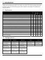
1.1
Key Features
Key Features of LINDY CPU Switch
CPU
CPU
2
4
CPU
CPU
CPU
4
8
16
OSD
OSD
OSD
Control multiple PCs from a single keyboard, monitor and mouse.
Yes
Yes
Yes
Yes
Yes
Control multiple PCs from a local and remote keyboard, monitor and mouse.
No
No
Yes
Yes
Yes
On-screen menu allows computers to be selected by name.
No
No
Yes
Yes
Yes
SmartBoot feature automatically boots all machines during power up.
Yes
Yes
Yes
Yes
Yes
Duplicate control ports allow local and remote keyboard / monitor / mouse access.
No
No
Yes
Yes
Yes
Mixed AT/PS2 keyboards and PS2/RS232 mice supported as standard.
Yes
Yes
Yes
Yes
Yes
Can be cascaded to provide a video switching network.
Yes
Yes
Yes
Yes
Yes
OVQ circuit ensures Optimum Video Quality even over extended distances.
Yes
Yes
Yes
Yes
Yes
Password security prevents unauthorised use.
Yes
Yes
Yes
Yes
Yes
Remote control module for convenient operation.
No
Yes
Yes
Yes
No
Channel switching by on-screen display
No
No
Yes
Yes
Yes
Channel switching by front panel key, keyboard hotkey, or button mouse.
Yes
Yes
Yes
Yes
Yes
Automatically restores keyboard and mouse states when channel changed.
Yes
Yes
Yes
Yes
Yes
Can be controlled remotely via an RS232 serial port.
No
Yes
Yes
Yes
Yes
Supports high bandwidth monitors at resolutions up to 1600 x 1200.
Yes
Yes
Yes
Yes
Yes
Includes screen saver, auto-scan and variable hotkey options.
No
No
Yes
Yes
Yes
Confirmation of selected ports on local and cascaded LINDY CPU Switches.
No
No
Yes
Yes
Yes
Supports keyboard modes 1,2 and 3 and mouse prompt and stream modes for
No
No
Yes
Yes
Yes
maximum compatibility.
1.2
Package contents
LINDY CPU 16
LINDY CPU 8
LINDY CPU 4
LINDY CPU 4
LINDY CPU 2
OSD Switch
OSD Switch
OSD Switch
Switch
Switch
LINDY CPU Switch.
LINDY CPU Switch.
LINDY CPU Switch.
LINDY CPU Switch.
LINDY CPU Switch.
Power supply suitable
Power supply suitable
Power supply suitable
Power supply suitable
Power supply suitable
for your country.
for your country.
for your country.
for your country.
for your country.
This installation guide.
This installation guide.
This installation guide.
This installation guide.
This installation guide.
6 x stick on self-
6 x stick on self-
6 x stick on self-
adhesive rubber feet.
adhesive rubber feet.
adhesive rubber feet.
2 x mounting brackets
2 x mounting brackets
2 x mounting brackets
for fixing the unit into a
for fixing the unit into a
for fixing the unit into a
19 inch rack.
19 inch rack.
19 inch rack.
6 x screws for fixing
4 x screws for fixing
4 x screws for fixing
mounting brackets to
mounting brackets to
mounting brackets to
the LINDY CPU Switch.
the LINDY CPU Switch.
the LINDY CPU Switch.
Page 4
Installation & Use – English Guide
LINDY ELECTRONICS LTD
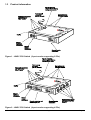
1.3
Product information
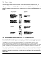
Figure 1 - LINDY CPU Switch (2 port version supporting 2 PCs)
Figure 2 - LINDY CPU Switch (4 port version supporting 4 PCs)
LINDY ELECTRONICS LTD
Installation & Use – English Guide
Page 5
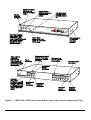
Figure 3 – LINDY CPU 4 OSD Switch Front & Rear views (4 port version supporting 4 PCs)
Page 6
Installation & Use – English Guide
LINDY ELECTRONICS LTD
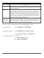
Figure 4 – LINDY CPU 8 OSD Switch Front & Rear views (8 port version supporting 8 PCs)
Figure 5 - Remote control pad / display
(Optional accessory not for use with the LINDY CPU 2 or LINDY CPU 16 OSD Switches)
LINDY ELECTRONICS LTD
Installation & Use – English Guide
Page 7
Figure 6 – LINDY CPU 16 OSD Switch Front & Rear views
(16 port version supporting 16 PCs)
Page 8
Installation & Use – English Guide
LINDY ELECTRONICS LTD
2. Installation
2.1
What you will need
•
Cables to connect the LINDY CPU Switch to each of your PC keyboard, video and mouse
ports. Cable specifications are given in appendix B. (You do not need to connect a mouse
cable if you are not using the mouse).
•
A monitor with a standard VGA/SVGA (15 pin) connector that will work when connected directly
to each of your PCs. LINDY CPU Switch supports low and high resolution monitors.
•
A standard AT or PS/2 style keyboard. If you are using an AT keyboard with a 5 pin connector
you may connect this to the LINDY CPU Switch using a standard AT to PS/2 keyboard adapter.
•
A PS/2 style two or three button Microsoft® or Logitech® compatible mouse or a Microsoft®
IntelliMouse compatible mouse. If you wish to use the mouse to switch the LINDY CPU
Switch’s channel then you will need a three button mouse or an IntelliMouse.
(The LINDY CPU Switch supports ‘Internet Mice’ that are compatible with the Microsoft®
IntelliMouse. These are fitted with a wheel or other scroll control and sometimes have
additional buttons. Examples are: Microsoft® IntelliMouse, Logitech® Pilot Mouse+, Logitech®
MouseMan+, Genius® NetMouse and Genius® NetMouse Pro).
•
•
A suitable mouse driver for your PCs. Supported types are:
• PS/2 or RS232 two button mouse driver (any manufacturer).
•
Microsoft® mouse driver (including IntelliMouse).
•
Logitech® mouse driver (including two button, three button and wheel mouse).
Use of PS/2 and RS232 style mice with the LINDY CPU Switch - All of the mouse connections
from LINDY CPU Switch to PCs support either a PS/2 or an RS232 mouse. LINDY CPU Switch
automatically converts from the PS/2 mouse commands to RS232 serial mouse commands.
Serial mice types are selected by using an adapter as described in Appendix B. This adapter is
the same as is shipped with Microsoft® auto-sensing mice. The LINDY CPU Switch will operate
without a mouse connected if you do not wish to use one.
LINDY ELECTRONICS LTD
Installation & Use – English Guide
Page 9
2.2
Mounting the LINDY CPU Switch
LINDY CPU 2 & 4 Switches
The LINDY CPU Switch has been
designed to be used either on a
desktop or mounted close to the
computer system boxes which it is
serving. If the LINDY CPU Switch is
mounted away from the desktop, you
may find the optional remote control
keypad/display unit a useful
accessory (not for use with 2 port
version)
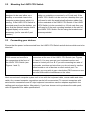
2.3
LINDY CPU 4 OSD, 8 OSD & 16 OSD Switches
The LINDY CPU Switch has been designed to be used
either on a desktop or mounted in a 19 inch rack. If the
LINDY CPU Switch is to be used on a desktop then you
will need to stick the supplied self-adhesive rubber feet
to the underside of the LINDY CPU Switch. If the LINDY
CPU Switch is to be mounted in a 19 inch rack then you
will need to fit the rack mounting brackets to the side of
the LINDY CPU Switch. Do this using the brackets and
screws provided.
Connecting your devices
Ensure that the power is disconnected from the LINDY CPU Switch and all devices which are to be
attached.
LINDY CPU 2 & 4 Switches
Connect the shared keyboard,
PS/2 mouse and monitor to
the connectors at the front of
the LINDY CPU Switch (see
Figures 1 and 2).
LINDY CPU 4 OSD, 8 OSD & 16 OSD Switches
Connect the shared keyboard, PS/2 mouse and monitor to the
connectors at the rear of the LINDY CPU Switch (see Figures
3, 4 and 6). You may connect your keyboard monitor and
mouse to control port A or B. If you are connecting two sets of
keyboards, monitors and mice then you do not need to use the
same brands or mix of devices on each control port. For
example, you may wish to use a two button PS/2 mouse on one
port and a Microsoft® IntelliMouse on the other.
Next connect each computer system unit in turn with the keyboard cable, mouse cable and video
cable. Any unused computer connections can be left unconnected. To connect computers with
serial mouse connections and AT style keyboard connections use the adapters supplied in the
cabling pack as shown below. Alternatively, if you have chosen not to purchase the cable pack,
refer to Appendix B for cable specifications.
Page 10
Installation & Use – English Guide
LINDY ELECTRONICS LTD
The LINDY CPU Switch is now ready for connection to the mains using the mains power adapter
supplied. It is important to apply power to the LINDY CPU Switch first, then power on the monitor
and each of the computers in turn. Failure to switch the LINDY CPU Switch and computers on in
the correct order can lead to the mouse and/or keyboard not being recognised by the computers
when they are switched on.
2.4
Configuring your PCs
Configure your PC in the same way that you would if your keyboard, mouse and monitor were all
connected directly to your PC, but bearing in mind the following points:
•
LINDY CPU Switch emulates Microsoft® compatible serial, IntelliMouse and PS/2 mice, so
ensure that your PC software is configured for a Microsoft® mouse of the correct type. Refer to
the list of supported drivers in section 2.1.
•
LINDY CPU Switch supports VGA/SVGA (XGA/XGA2 only supported by OSD models) type
monitors, but does not support the automatic detection features available with some ‘plug and
play’ monitors and video cards. If you have this type of video card and monitor, you should
select the video mode manually instead of relying upon the automatic detection feature.
2.5
Other useful installation information
PC boot up sequence - When your PCs are powered on they communicate with any attached
keyboards and mice and setup parameters required by the particular operating system. It is
necessary for the LINDY CPU Switch to be attached and powered on during this sequence so that
it can give the required responses and keep track of all the modes and settings requested by each
of the connected PCs.
LINDY ELECTRONICS LTD
Installation & Use – English Guide
Page 11
Mouse characteristics - do not unplug a PS/2 mouse connection from a PC whilst the PC is on.
Due to the design of PS/2 mice communications the mouse function on the PC will be lost and you
will have to re-boot the PC to regain normal operation. Unplugging the mouse from the LINDY
CPU Switch will also cause it to stop operating when it is plugged back in. RS232 mice can usually
be unplugged and plugged back in provided that a mouse was connected when the operating
system initially booted. The LINDY CPU Switch is fitted with a PS/2 mouse recovery system which
allows you to disconnect and re-connect the shared mouse without powering down the system
(although this is generally not advisable) - see section 2.6 for details.
Keyboard and mouse mode switching - The LINDY CPU Switch keeps a log of the keyboard
and mouse mode and resolution settings requested by each of the connected PCs. These settings
are automatically restored to the shared keyboard and mouse when the LINDY CPU Switch
channel is switched thus ensuring maximum software compatibility. The <NUM LOCK>, <CAPS
LOCK> and <SCROLL LOCK> states are an obvious example of this process.
2.6
Re-enabling a disconnected PS/2 mouse
If you disconnect the shared PS/2 mouse from the LINDY CPU Switch by accident during
operation then the mouse operation will be lost when the mouse is plugged back in. To avoid
having to reboot the entire system in this situation the LINDY CPU Switch is fitted with an
automatic mouse recovery system.
With the PS/2 mouse disconnected, change the channel using the keypad or keyboard hotkeys.
The LINDY CPU Switch detects that the mouse has been disconnected and triggers the automatic
recovery system. Plug in the PS/2 mouse and the LINDY CPU Switch will re-initialise it.
IMPORTANT NOTE
LINDY CPU 4 OSD, 8 OSD & 16 OSD Switches only
Alternatively you can reset the keyboards and mice by holding the SELECT and AUTO
keys down together for 5 seconds. A complete power off reset of the connected
keyboards and mice will then be performed. This function only resets the shared
keyboard and mice that are plugged into ports A and B. It does not affect the status of
any of the other ports on the switch or the CPU connections.
Page 12
Installation & Use – English Guide
LINDY ELECTRONICS LTD
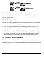
2.7
Hot plugging the LINDY CPU Switch into running systems and
re-enabling disconnected CPU PS/2 mouse connections
It is advisable to switch off the systems that are going to be connected to the LINDY CPU Switch
before installation. However if this is not possible then most systems can be hot plugged by using
the LINDY CPU Switch’s mouse restoration functions. The keyboard connection will normally
restore itself automatically.
On many PCs, mouse movement will be lost if the PS/2 mouse is unplugged and plugged back in
whilst the PC is running. Mouse movement can then only be restored by rebooting the PC. This is
because the mouse drivers only setup and enable the mouse when the PC is initially booted.
If you have switched off your LINDY CPU Switch or you are attempting to ‘hot plug’ it into a system
that is already running, you may be able to restore lost mouse movement using the LINDY CPU
Switch's mouse restoration functions.
IMPORTANT NOTE
Mouse restoration functions should be used with care as unpredictable results may occur
if the wrong mouse type is selected. If in doubt restore the mouse by powering down the
PC normally.
Standard PS/2 mouse data uses a different data format to IntelliMouse data and so two reset
functions are provided on the LINDY CPU Switch. The type of data format expected by the PC
depends upon the driver and the type of mouse that was connected when the driver was booted.
The following table may be used as a guide. Note that the mouse reset functions predict the likely
mouse resolution settings but may not restore the speed or sensitivity of the mouse exactly as they
were when the PC originally booted.
Type of mouse / system
Connected at bootup
PS/2
PS/2
IntelliMouse / LINDY CPU Switch
IntelliMouse / LINDY CPU Switch
LINDY ELECTRONICS LTD
Driver type
PS/2 only
IntelliMouse
PS/2 only
IntelliMouse
Likely expected
data format
PS/2
PS/2
PS/2
IntelliMouse
Installation & Use – English Guide
Suggested
restoration
F5
F5
F5
F6
Page 13
To restore lost mouse movement on a CPU connected to the LINDY CPU Switch:
1) Select the CPU that has lost its mouse movement
2) Press the select key on the front of the LINDY CPU Switch for 5 seconds until ‘C’ is displayed.
You are now in configure mode.
3) To restore a PS/2 mouse connection press
) <ENTER>
Or, to restore an IntelliMouse connection press
) <ENTER>
4) Exit from configure mode by typing
( <ENTER>
5) Test the mouse movement by moving the mouse a short distance.
F5 - Restore PS/2 mouse function
F6 - Restore IntelliMouse function
Page 14
Installation & Use – English Guide
LINDY ELECTRONICS LTD
3. Using the LINDY CPU Switch
This section explains the general operation of the LINDY CPU Switch. We recommend that you
read this section before starting to use the product.
3.1
Power on status
At power on the LINDY CPU Switch selects PC number 1 and displays '1'. If a password has been
set then ‘P’ will be displayed and the LINDY CPU Switch will remain locked until a valid password
is entered. The 16 port model is also fitted with a power indicator.
3.2
Status lights (4 OSD, 8 OSD & 16 OSD Versions only)
The green CPU status lights (1-16) show the on/off status of the connected CPUs. This status is
derived from the CPU keyboard connection and operates even when the LINDY CPU Switch is
powered off.
The red status lights (A and B) show the activity status of the local and remote keyboard / monitor /
mouse control ports. When port A is active port B is disabled and vice versa. A port becomes
active and the associated light comes on when keyboard or mouse data activity has been
detected. When no keyboard or mouse data has been detected for the timeout period (see section
4.4) the port becomes inactive, the light goes out and the other port can then be used.
LINDY ELECTRONICS LTD
Installation & Use – English Guide
Page 15
3.3
Front panel keys and remote controller
KEY
SELECT key
LINDY
LINDY
LINDY
LINDY
LINDY
CPU 2
CPU 4
CPU 4 OSD
CPU 8 OSD CPU 16 OSD
The SELECT key is used to select which channel is currently controlled by
the shared keyboard, mouse and monitor ports. It is also used to enter
configuration mode (see section 4). Pressing the key during normal operation
will cause the next channel to be selected.
Cycle around Cycle around Cycle around Cycle around Cycle around
ports 1 & 2
ports 1, 2, 3
ports 1, 2, 3
ports 1, 2, 3, ports 1, 2, 3,
&4
&4
4, 5, 6, 7 & 8 4, 5, 6, 7, 8,
9, 10 ,11, 12,
13, 14, 15 &
16
An optional remote controller is also available
Not
Not
compatible which replicates the SELECT key and
compatible
display, but can be located remotely from the
LINDY CPU Switch. This is particularly useful
in applications where the LINDY CPU Switch
is located away from the desktop. The
remote controller can be conveniently
attached to your keyboard with a couple of
Velcro strips to give instant channel
information and key control.
AUTO key
Not
compatible
AUTO and
SELECT keys
pressed together
(Lock function)
Not
compatible
AUTO and
SELECT keys
pressed together
for 5 seconds
(keyboard and
mouse reset
function)
Not
compatible
Page 16
The AUTO key puts the LINDY CPU Switch into auto-scan
mode. The ports scanned and the scan time can be selected
by options L and T in configure mode (see section 4.4).
Pressing the AUTO and SELECT keys together will cause
the LINDY CPU Switch to select channel 0 and disable all
video output. If a security password has been set then the
LINDY CPU Switch will lock, display P and wait for the
password to be entered before unlocking the LINDY CPU
Switch.
After 5 seconds the LINDY CPU Switch’s display will blank
and power to the shared keyboards and mice will be switched
off causing a complete reset of these devices. After several
further seconds the power will be re-applied and normal
operation is resumed. This reset function does not reset the
computer connections to the LINDY CPU Switch.
Installation & Use – English Guide
LINDY ELECTRONICS LTD
3.4
Status display
The status display usually shows the currently selected port. If autoscan mode is selected, the
segments will illuminate in sequence in a clockwise direction interspersed with a display of the
currently selected channel. If LINDY CPU Switch has been locked, ‘P’ will be displayed until a valid
password has been typed to unlock the unit. Data flow from the mouse or keyboard causes the dot
to flash.
3.5
Using the dual control ports (A and B) - OSD versions only
The LINDY CPU Switch is fitted with two control ports, A and B. Each control port has a keyboard,
mouse and monitor connection. Either control port may be used to access the LINDY CPU Switch.
Typically port A may be used for local access and port B for remote access (up to 20 metres
away). The video picture is duplicated on both ports and the LINDY CPU Switch will accept
keyboard and mouse data from one control port at a time. Whilst the other port is active, the <NUM
LOCK>, <CAPS LOCK> and <SCROLL LOCK> keys on the inactive control port’s keyboard will
flash indicating that the port is currently disabled. Once there has been no keyboard or mouse data
on the active control port for the timeout period, the other keyboard can be used. Once activity is
detected then this new port becomes the active port and the other port is disabled. The currently
active port is indicated on the front panel. If neither the A or B lights are on then either control port
may be used.
LINDY ELECTRONICS LTD
Installation & Use – English Guide
Page 17
3.6
Keyboard hotkey control
LINDY CPU Switch can be conveniently controlled by selecting channel, autoscan mode or
security locking from the keyboard. All of the hotkey control commands are invoked by holding
down the two hotkeys and then pressing a command key. By default, the two hotkeys are t and
s, although other combinations can be selected by reconfiguring the hotkeys (see section 4.7).
Once the hotkey command has been activated you will need to release the hotkeys and the
command key before a new hotkey command is accepted by the LINDY CPU Switch. HOTKEYs +
v is an exception and this allows you to 'tab through' the ports by holding down the hotkeys and
repeatedly pressing v.
The hotkey command are summarised below
(note that the numbers on the numeric keypad do not form part of a valid hotkey) :
Hotkey Sequence
CPU 16 OSD
CPU 8 OSD
CPU 4 OSD
CPU 4
CPU 2
‘HOTKEYs’ & Select channel 1
Select channel 1
Select channel 1
Select channel 1
Select channel 1
‘HOTKEYs’ & Select channel 2
Select channel 2
Select channel 2
Select channel 2
Select channel 2
‘HOTKEYs’ & Select channel 3
Select channel 3
Select channel 3
Select channel 3
-
‘HOTKEYs’ & Select channel 4
Select channel 4
Select channel 4
Select channel 4
-
‘HOTKEYs’ & Select channel 5
Select channel 5
-
-
-
‘HOTKEYs’ & Select channel 6
Select channel 6
-
-
-
‘HOTKEYs’ & Select channel 7
Select channel 7
-
-
-
‘HOTKEYs’ & Select channel 8
select channel 8
-
-
-
‘HOTKEYs’ & Select channel 9
-
-
-
-
‘HOTKEYs’ & Select channel 10
-
-
-
-
‘HOTKEYs’ & Select channel 11
-
-
-
-
‘HOTKEYs’ & Select channel 12
-
-
-
-
‘HOTKEYs’ & Select channel 13
-
-
-
-
‘HOTKEYs’ & Select channel 14
-
-
-
-
‘HOTKEYs’ & Select channel 15
-
-
-
-
‘HOTKEYs’ & Select channel 16
-
-
-
-
‘HOTKEYs’ & v
‘HOTKEYs’ & Selects the next channel
Switches off the video signal and display 0. This will cause some monitors to go into standby mode or
switch off. The video signal can be re-enabled by selecting a channel
Page 18
Installation & Use – English Guide
LINDY ELECTRONICS LTD
Hotkey Sequence
CPU 4 OSD, 8 OSD and 16 OSD Only
‘HOTKEYs’ & 0
Displays the on screen menu for selecting
computers by name
‘HOTKEYs’ & $
Selects autoscan mode where each channel is displayed for the selected time (see section
4.4). To cancel autoscan mode simply select any fixed channel either by hotkey or using the
LINDY CPU Switch button.
‘HOTKEYs’ & /
Disables the LINDY CPU Switch 's shared keyboard and mouse and displays 0. The video
signal is switched off. If a password has not been set then the LINDY CPU Switch can be reenabled by selecting a channel. If a password has been set then the LINDY CPU Switch
displays 'P' to indicate that a valid password must be entered to unlock the switch. Simply
type the same key combination as was set during configuration (see section 4.9) then press
the <ENTER> key. Note - if anyone has typed at the keyboard whilst in secure mode, it will
be necessary to press the <ENTER> key first to clear the invalid password, then type the
valid password followed by pressing <ENTER> again.
‘HOTKEYs’ & 2
then {number}
(where {number} is
0, 1, 2, 3, 4, 5, 6, 7,
8 or 9).
Selects the channel specified by {number}. This allows ports on cascaded
units to be selected. For example hotkeys + 010216 would select port 1 (01)
on the current LINDY CPU Switch, port 2 (02) on the next cascaded LINDY
CPU Switch and port 16 on the last LINDY CPU Switch.
Examples of common hotkey sequences (assuming
t + s hotkey option):
To select channel 2:
press
ts release ts
To 'tab through' channels:
press
tsv release v press v
Release
v press v release vts
To select channel 15 (on a CPU 16 OSD):
ts release press release ts
press
LINDY ELECTRONICS LTD
Installation & Use – English Guide
Page 19
3.7
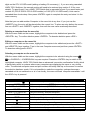
On Screen Menu control
IMPORTANT NOTE
This next section dealing with the On Screen Menu control is a feature only supported on the
LINDY CPU 4 OSD, 8 OSD & 16 OSD versions.
LINDY CPU SWITCH
Computer
Port
NT Server A
355
NT Server B
356
Local IBM PC
1
Local Compaq PC
2
Web Browser
4
Comms Server A
5
Comms Server B
6
Fred’s PC
7
Dot shows
currently
selected
computer
On-screen menu (CPU 4 OSD & CPU 8 OSD) Port numbers are entered as single digits
LINDY CPU SWITCH
Computer
Port
NT Server A
030505
NT Server B
030506
Local IBM PC
01
Local Compaq PC
02
Web Browser
04
Comms Server A
05
Comms Server B
06
Fred’s PC
07
Dot shows
currently
selected
computer
On-screen menu (CPU 16 OSD) Port numbers are entered as
double digits with leading zeros where required
LINDY CPU Switch can conveniently select a computer using the integral On Screen Menu control.
The menu is called up by pressing the two ‘HOTKEYs’ and 0. When the menu is first called up,
there will be no named computers listed. You must first enter the names and port numbers for
computers which are to be selected from the menu.
Adding a computer to the menu list
With the menu visible on the screen, press the <INSERT> key. This will cause a new Computer
entry field to be inserted on the menu. This is highlighted in red with a flashing cursor to indicate
the text entry position. Type in a name up to 16 characters long. You can use upper/lower case,
special and space characters. When completed press the <ENTER> key. The red highlighted area
now moves into the Port entry field and you can enter the port number for the named Computer.
Port numbers are specified using single digits on the CPU 4 OSD and 8 OSD models and double
Page 20
Installation & Use – English Guide
LINDY ELECTRONICS LTD
digits on the CPU 16 OSD model (adding a leading 0 if necessary). ). If you are using cascaded
LINDY CPU Switches, the cascade routing will need to be entered (see section 3.10 for more
details). To specify port 5 on a LINDY CPU Switch that is cascaded off port 3 you would enter port
number 35 (CPU 4 OSD & CPU 8 OSD models) or 0305 (CPU 16 OSD model). Units can be
cascaded three levels deep. Now press <ENTER> again to complete the entry and store it in the
menu memory.
Note that you can add another Computer to the menu list at any time. If you just use the
<INSERT> key, the entry will be placed after the current line. To place an entry before the current
line use <SHIFT> and <INSERT> together, then edit the new name as already described.
Deleting a computer from the menu list
With the menu visible on the screen, highlight the computer to be deleted and press the
<DELETE> key. To confirm deletion press <ENTER>. To abandon deletion press <ESC>.
Editing a computer on the menu list
With the menu visible on the screen, highlight the computer to be edited and press the <SHIFT>
and <DELETE> keys together. Type in the new Computer name and port then press <ENTER>.
To abandon editing press <ESC>.
Selecting a computer on the menu list
With the menu visible on the screen, highlight the computer to be selected using the cursor p /
o or <PAGEUP> / <PAGEDOWN> keys as required. Press the <ENTER> key to switch to the
highlighted computer. LINDY CPU Switch has an advanced ‘connection confirmation’ facility which
is particularly useful in systems where many computers are displaying the same or very similar
video. The selected computer name and port number will briefly flash up on the screen to confirm
the selection has been made. If it is not possible to make the connection, perhaps because a
cascaded unit is not switched on or is in use locally, the menu will flash ‘computer unavailable’ until
the <ESC> key is pressed.
KEY
HOTKEYs’ and 0
<INSERT>
<SHIFT> & <INSERT>
<DELETE>
<SHIFT> & <DELETE>
<ENTER>
<ESC>
p
o
<PAGEUP>
<PAGEDOWN>
LINDY ELECTRONICS LTD
FUNCTION
Calls the menu up onto the screen (even if no PC video exists)
Adds a computer entry AFTER the currently selected line
Adds a computer entry BEFORE the currently selected line
Deletes the currently selected computer
Edits the currently selected computer
Confirms an entry or selects a computer
Quits from editing a line or quits from the menu
Moves up the menu by one line
Moves down the menu by one line
Moves to the top of page or up 8 lines if more than 8 present
Moves to bottom of page or down 8 lines if more than 8 present
Installation & Use – English Guide
Page 21
3.8
Mouse control
The channels can conveniently be changed on the LINDY CPU Switch by using a three button
mouse or IntelliMouse. In order to switch to the next channel simply hold down the central mouse
button or wheel button and click on the left hand mouse button. The channel will then change.
3.9
RS232 control
IMPORTANT NOTE
RS232 control is supported on all LINDY CPU Switches except the LINDY CPU 2 Switch
LINDY CPU Switch can be controlled by a remote RS232 device. To select a channel the data rate
of the sending device must be set to 1200 baud, 8 bits, no parity and 1 stop bit. No handshaking is
used by the LINDY CPU Switch. Simply send the character for the channel which needs to be
selected, for example ASCII ‘1’ (hex code 31) will select channel 1, ASCII ‘2’ (hex code 32) will
select channel 2 and so on. Ports 10, 11, 12, 13, 14, 15 and 16 are selected by sending ASCII
codes A, B, C, D, E, F and G respectively.
3.10 LINDY CPU Switch Remote control
IMPORTANT NOTE
The remote control is only supported on the LINDY CPU 4, 4 OSD & 8 OSD Switches
This small remote control device (see figure 5) duplicates the LED and SELECT key off the front of
the LINDY CPU Switch to provide a remote means of switching channels. The status display
shows the channel selected and mouse / keyboard and data activity.
3.11
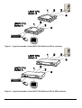
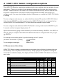
Cascading LINDY CPU Switches
Any number of LINDY CPU Switches can be connected together to expand the number of
connected computers. This can be particularly useful where clusters of computers are located
some distance from each other because each unit acts as data booster and can each be up to 30
metres away from the next LINDY CPU Switch. The channel can be selected on remote LINDY
CPU Switch units using an extension of the HOTKEY control function or using the On Screen
Menu which will store over 300 names. The On Screen Menu is recommended for selecting
computers on cascaded LINDY CPU Switches as this avoids the need to use long hotkey
sequences that may be hard to remember. When using the On Screen Menu, limit the cascade
depth to three levels (the maximum number of port digits that can be added to the menu).
Page 22
Installation & Use – English Guide
LINDY ELECTRONICS LTD
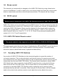
For example, consider a situation where two LINDY CPU Switch units are connected together (as
shown in figures 7 and 8). To connect to the computer attached to port 3 on LINDY CPU Switch B
the user would hold down the hotkey keys then press followed by , whilst keeping the hotkey
keys pressed. This will have the effect of connecting to port ‘3’ of the LINDY CPU Switch which is
connected into port ‘2’ of the first LINDY CPU Switch unit A. (Note: if you are cascading 16 port
models then you will need to type a leading 0 before all single digit port numbers).
For example to connect to port 3 on the LINDY CPU Switch cascaded off port 2 of your first LINDY
CPU Switch use:
press
ts release press
release ts
For example to connect to port 14 on the LINDY CPU 16 OSD Switch cascaded off port 1 of your
first LINDY CPU 16 OSD Switch use:
ts release press release press release press release ts
press
LINDY ELECTRONICS LTD
Installation & Use – English Guide
Page 23
Figure 7 - A typical cascade of two LINDY CPU Switches (CPU 4 versions)
Figure 8 - A typical cascade of two LINDY CPU Switches (CPU 8 OSD versions)
Page 24
Installation & Use – English Guide
LINDY ELECTRONICS LTD
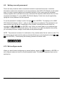
4. LINDY CPU Switch configuration options
The LINDY CPU Switch is supplied pre-configured with factory defaults which are suitable for most
applications. There are a number of more advanced features and functions which can be set by
the user. These are stored in the LINDY CPU Switch's EEPROM memory and are retained when
the power is disconnected. The options may be changed whilst the LINDY CPU Switch is in
configure mode. You may enter configure mode at initial power on or whilst the LINDY CPU Switch
is running.
To enter configure mode at power on, switch off all the attached PCs and the LINDY CPU Switch.
Hold down the SELECT key whilst powering on the LINDY CPU Switch. Do not release the key
until the LINDY CPU Switch displays 'C' to show that it has entered configure mode.
To enter configure mode whilst the LINDY CPU Switch is running, hold down the SELECT key for
5 seconds until the front panel display shows ‘C’.
Options are entered by typing a letter followed by a number followed by <ENTER>. Use <ESC> to
abort the entry of an option. The LINDY CPU Switch will remain in configure mode until you type
( <ENTER>.
For example: to set hotkey option 2 type the following at the 'C' prompt
+<ENTER>
(<ENTER>
(at LINDY CPU Switch 'C' prompt)
To exit configure mode type:
4.1 Screen saver time delay
LINDY CPU Switch contains a programmable screen saver which will blank the display after the
set time delay with no keyboard or mouse activity. Simply typing at the keyboard or moving the
mouse will re-enable the display. The display will flash whilst the LINDY CPU Switch is in screen
save mode.
CPU
KEYS
CONFIGURATION DESCRIPTION
%
%Blank screen after 1 minute of inactivity
%Blank screen after 2 minutes of inactivity
%Blank screen after 4 minutes of inactivity
%Blank screen after 8 minutes of inactivity
%Blank screen after 12 minutes of inactivity
%Blank screen after 16 minutes of inactivity
%Blank screen after 20 minutes of inactivity
Screen saver disabled (default)
LINDY ELECTRONICS LTD
CPU
CPU
CPU
CPU
2
4
4 OSD
8 OSD
16 OSD
Yes
Yes
Yes
Yes
Yes
Yes
Yes
Yes
Yes
Yes
Yes
Yes
Yes
Yes
Yes
Yes
Yes
Yes
Yes
Yes
Yes
Yes
Yes
Yes
Yes
Yes
Yes
Yes
Yes
Yes
Yes
Yes
Yes
Yes
Yes
Yes
Yes
Yes
Yes
Yes
Installation & Use – English Guide
Page 25
4.2
Display options
The LINDY CPU Switch display has a flashing dot which will activate whenever the keyboard or
mouse are used. Certain users may prefer to disable this flashing dot by setting the D2, D4 or D6
options. The remote control pad / display is designed to fit on the left or right hand side of the
keyboard or monitor. Select the mode required so that the port number appears in the correct
orientation. Modes D5 and D6 are special modes that support a monitor light module for use in
banking and dealing room applications where the keyboard and mouse only are being switched.
The monitor lights show which monitor is currently being controlled by the shared keyboard and
mouse.
KEYS
'
'
'
'
'
'
4.3
CPU
CPU
CPU
CPU
CPU
2
4
4 OSD
8 OSD
16 OSD
Display dot flashes to indicate activity, right handed auxiliary display (default)
Yes
Yes
No
No
No
Display dot does not flash, right handed auxiliary display
Yes
Yes
No
No
No
Display dot flashes to indicate activity, left handed auxiliary display
Yes
Yes
No
No
No
Display dot does not flash, left handed auxiliary display
Yes
Yes
No
No
No
Display dot flashes, auxiliary display port configured for monitor light module
Yes
Yes
No
No
No
Display dot does not flash, auxiliary port configured for monitor light module
Yes
Yes
No
No
No
CONFIGURATION DESCRIPTION
Display appearance options
Options are available to change the colour scheme of the On-Screen Display and the time that the
confirmation message remains on the screen after a channel has been selected.
KEYS
'
'
'
'
'
'
Page 26
CPU
CPU
CPU
CPU
CPU
2
4
4 OSD
8 OSD
16 OSD
Menu appears with magenta / blue background and green highlight (default)
No
No
Yes
Yes
Yes
Menu appears with red / blue background and green highlight
No
No
Yes
Yes
Yes
Menu appears with blue / black background and light blue highlight
No
No
Yes
Yes
Yes
Confirmation message remains on screen for standard time period (default)
No
No
Yes
Yes
Yes
Confirmation message remains on screen for short time period
No
No
Yes
Yes
Yes
Confirmation message remains on screen for extended time period
No
No
Yes
Yes
Yes
CONFIGURATION DESCRIPTION
Installation & Use – English Guide
LINDY ELECTRONICS LTD
4.4
Autoscan ‘lock on’ mode and delay time
LINDY CPU Switch can be set to select each channel in turn for a period of time set by the
Autoscan delay time. Autoscan mode is entered by typing the hotkey keys together with $. By
default, only those channels which have a powered up computer connected to them will be
scanned. Sometimes it may be desirable to scan all channels, even if the attached computer is
switched off (this will simply show a blank screen when it is selected). All the LINDY CPU Switch’s
ports will be scanned if option L2 is selected. Some applications may also require the LINDY CPU
Switch to power on in autoscan mode. This feature can be selected using the L3 or L4 options.
KEYS
/
/
/
/
7
7
7
7
7
7
7
7
CPU
CPU
CPU
CPU
CPU
2
4
4 OSD
8 OSD
16 OSD
LINDY CPU Switch locks on to active ports only during autoscanning (default)
Yes
Yes
Yes
Yes
Yes
LINDY CPU Switch locks on to every port during autoscanning
Yes
Yes
Yes
Yes
Yes
LINDY CPU Switch powers on in autoscan mode & locks on to active ports only
Yes
Yes
Yes
Yes
Yes
LINDY CPU Switch powers on in autoscan mode and locks on to all ports
Yes
Yes
Yes
Yes
Yes
2 seconds autoscan delay time before switching to next port (default)
Yes
Yes
Yes
Yes
Yes
5 seconds autoscan delay time before switching to next port
Yes
Yes
Yes
Yes
Yes
7 seconds autoscan delay time before switching to next port
Yes
Yes
Yes
Yes
Yes
10 seconds autoscan delay time before switching to next port
Yes
Yes
Yes
Yes
Yes
15 seconds autoscan delay time before switching to next port
Yes
Yes
Yes
Yes
Yes
20 seconds autoscan delay time before switching to next port
Yes
Yes
Yes
Yes
Yes
30 seconds autoscan delay time before switching to next port
Yes
Yes
Yes
Yes
Yes
60 seconds autoscan delay time before switching to next port
Yes
Yes
Yes
Yes
Yes
CONFIGURATION DESCRIPTION
NOTE: Autoscan mode is ended simply by selecting a fixed channel using the on-screen menu,
the keypad, the keyboard hotkeys or the mouse.
Many modern monitors are fitted with automatic power save relays and will switch off after a few
seconds if connected to an inactive PC. If you are using such a monitor you must not use the L2
feature. Constant switching on and off of your monitor's relay will eventually damage your
monitor.
LINDY ELECTRONICS LTD
Installation & Use – English Guide
Page 27
4.5
Timeout setting for switching between the local and remote
keyboard/mouse ports (A and B)
If you are controlling the LINDY CPU Switch from two locations then you will have connected
keyboards, monitors and mice to the local and remote ports (A and B). The LINDY CPU Switch will
accept keyboard and mouse data from either location and the video is duplicated on both monitors.
Only one of the ports may be used at a time. The other port is automatically disabled although the
video continues to be displayed. This port is re-enabled for keyboard and mouse data when there
has been no activity from the currently active port for the switchover timeout period. This timeout
period is selectable from 2 seconds to 10 minutes using the ‘S’ options in configure mode as
follows:
CPU
KEYS
CONFIGURATION DESCRIPTION
6
6
6
6
6
6
6
4.6
CPU
CPU
CPU
CPU
2
4
4 OSD
8 OSD
16 OSD
2 seconds of inactivity before allowing switchover between A & B ports (default)
No
No
Yes
Yes
Yes
5 seconds of inactivity before allowing switchover between A & B ports
No
No
Yes
Yes
Yes
10 seconds of inactivity before allowing switchover between A & B ports
No
No
Yes
Yes
Yes
30 seconds of inactivity before allowing switchover between A & B ports
No
No
Yes
Yes
Yes
1 minute of inactivity before allowing switchover between A & B ports
No
No
Yes
Yes
Yes
5 minutes of inactivity before allowing switchover between A & B ports
No
No
Yes
Yes
Yes
10 minutes of inactivity before allowing switchover between A & B ports
No
No
Yes
Yes
Yes
Mouse mode and mouse switching of channels
A three button PS/2 mouse can be used to switch channels on the LINDY CPU Switch by default.
To switch to the next channel, the user simply holds down the central button or wheel button and
presses the left hand button to change channel. If the user does not wish to take advantage of this
feature, it can be disabled by selecting U2, U3 or U5. If the third button is being used to switch the
LINDY CPU Switch then it is not available for use with PC software. Consequently in modes U1,
U2 and U4 the LINDY CPU Switch reports to the PCs that a 2 button mouse is connected. If you
wish to use the full function of a 3 button mouse or IntelliMouse for your PC software then you
should select option U3 or U5.
The LINDY CPU Switch supports ‘Internet Mice’ that are compatible with the Microsoft
IntelliMouse. These are fitted with a wheel or other scroll control and sometimes have additional
buttons. Examples are:
Microsoft® IntelliMouse
Genius® NetMouse
Logitech® Pilot Mouse +
Genius® NetMouse Pro
Logitech® MouseMan+
Page 28
Installation & Use – English Guide
LINDY ELECTRONICS LTD
Standard PS/2 and IntelliMouse compatible mice can be connected to control ports A and B in any
combination. You may configure your CPUs using Microsoft PS/2 or IntelliMouse drivers in any
combination as required. The IntelliMouse features are supported on both PS/2 and RS232 CPU
connections. When using PS/2 CPU connections, the LINDY CPU Switch will automatically
configure itself to the type of mouse requested by the driver. If you are using RS232 CPU
connections then you will need to select mouse options U4 or U5 to enable the IntelliMouse
features.
CPU
KEYS
CONFIGURATION DESCRIPTION
8
LINDY CPU Switch channels are switchable using a 3 button mouse or
8
LINDY CPU Switch channels are not switchable using 3 button mouse or
8
LINDY CPU Switch channels are not switchable using 3 button mouse or
8
LINDY CPU Switch channels are switchable using 3 button mouse or
8
LINDY CPU Switch channels are not switchable using 3 button mouse or
4.7
CPU
CPU
CPU
CPU
2
4
4 OSD
8 OSD
16 OSD
Yes
Yes
Yes
Yes
Yes
Yes
Yes
Yes
Yes
Yes
Yes
Yes
Yes
Yes
Yes
Yes
Yes
Yes
Yes
Yes
Yes
Yes
Yes
Yes
Yes
IntelliMouse (default)(LINDY CPU Switch reports 2 button mouse mode to PCs)
IntelliMouse (LINDY CPU Switch reports 2 button mouse mode to PCs)
IntelliMouse (LINDY CPU Switch reports 3 button mouse mode to PCs)
IntelliMouse (LINDY CPU Switch reports IntelliMouse mode to PCs)
IntelliMouse (LINDY CPU Switch reports IntelliMouse mode to PCs)
Keyboard hotkey combination
The keyboard hotkey combination is used to change a channel, set autoscan mode or secure the
product (so that the password needs to be typed before it can be used again). The following
keyboard hotkey combinations can be selected. These hotkey combinations are used together with
the command keys to trigger the required LINDY CPU Switch function. The left and right shift key
combination is particularly suitable for extended keyboards where additional keys can be
programmed to act as a combination of other keys. Such keyboards are supplied with many
Gateway 2000 computers. Programming spare keys to trigger the hotkey combination allows
channels to be selected via a single key stroke.
KEYS
CONFIGURATION DESCRIPTION
+ t and s keys together (left or right hand keys operate) (default)
+ t and u keys together (left or right hand keys operate)
+ s and u keys together (left or right hand keys operate)
+ RIGHT s key
+ LEFT s and RIGHT s keys together
+ LEFT t and LEFT s keys together
+ RIGHT t and RIGHT s keys together
+ No hotkey enabled
LINDY ELECTRONICS LTD
Installation & Use – English Guide
CPU
CPU
CPU
CPU
CPU
2
4
4 OSD
8 OSD
16 OSD
Yes
Yes
Yes
Yes
Yes
Yes
Yes
Yes
Yes
Yes
Yes
Yes
Yes
Yes
Yes
Yes
Yes
Yes
Yes
Yes
Yes
Yes
Yes
Yes
Yes
Yes
Yes
Yes
Yes
Yes
Yes
Yes
Yes
Yes
Yes
Yes
Yes
Yes
Yes
Yes
Page 29
4.8
Firmware functions (version query, mouse restore and reset)
For technical support purposes, it may be necessary to find the firmware release version for the
control software in your LINDY CPU Switch. For example, if the release version is v1.02 the
response shown to )<ENTER> will be a brief display of the digit ‘1’, then )<ENTER> will be
a brief display of the digit ‘0’, then )<ENTER> will be a brief display of the digit ‘2’. You can
reset all of the configured options back to the factory default states by typing F8. Use options F5
and F6 to restore mouse function on disconnected PS/2 CPU mouse connections. See section 2.7
for full details
CPU
KEYS
)
)
)
)
)
)
Page 30
CONFIGURATION DESCRIPTION
CPU
CPU
CPU
CPU
2
4
4 OSD
8 OSD
16 OSD
Display firmware first digit
Yes
Yes
Yes
Yes
Yes
Display firmware second digit
Yes
Yes
Yes
Yes
Yes
Display firmware third digit
Yes
Yes
Yes
Yes
Yes
Restore PS/2 mouse function to the currently selected CPU’s mouse port
Yes
Yes
Yes
Yes
Yes
Restore IntelliMouse function to the currently selected CPU’s mouse port
Yes
Yes
Yes
Yes
Yes
RESET all configurations to factory default settings. An ‘r’ will show briefly on
Yes
Yes
Yes
Yes
Yes
the display to confirm that the reset has been completed
Installation & Use – English Guide
LINDY ELECTRONICS LTD
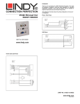
4.9
Setting a security password
There are many situations where unrestricted access to corporate file servers or sensitive
information needs to be controlled. In such circumstances, the LINDY CPU Switch can be locked
away in a room or secure cabinet and controlled remotely. In this mode typing the keyboard
hotkeys together with 0 will blank the screen, disconnect the keyboard and mouse from all of the
computers and display ‘P’ on the LINDY CPU Switch display. Control can only be regained by
typing the correct password on the keyboard.
To set the password in configure mode, first type 3 then <ENTER>. The display on the LINDY
CPU Switch will change to show ‘=‘ and you can then type your password. The password is not
case sensitive and can be any combination of key strokes, including the function keys, but
excluding the t , s , u and <ENTER> keys. When you have typed in your password type
<ENTER> to register it in the stored memory. Do not worry if you type the password incorrectly,
you can always re-enter configure mode and set the password again.
NOTE - The password consists of a combination of key strokes rather like the code to a safe. The
key strokes are not case sensitive and can include all the keys on the keyboard (except t , s ,
u and <ENTER>). Consequently the following 'password' would be valid:
e)5('
4.10 Exit configure mode
When you have finished configuring any special options, simply type ( followed by <ENTER> to
exit configure mode and return to normal operation mode. The attached computers can now be
switched on.
LINDY ELECTRONICS LTD
Installation & Use – English Guide
Page 31
Appendix A.
KEYS
%
%
%
%
%
%
%
%
'
'
'
'
'
'
'
'
'
'
'
'
)
)
)
)
)
)
LINDY CPU Switch
Configuration Summary
CPU
CPU
CPU
CPU
CPU
2
4
4 OSD
8 OSD
16 OSD
Screen saver disabled (default)
Yes
Yes
Yes
Yes
Yes
Blank screen after 1 minute of inactivity
Yes
Yes
Yes
Yes
Yes
Blank screen after 2 minutes of inactivity
Yes
Yes
Yes
Yes
Yes
Blank screen after 4 minutes of inactivity
Yes
Yes
Yes
Yes
Yes
Blank screen after 8 minutes of inactivity
Yes
Yes
Yes
Yes
Yes
Blank screen after 12 minutes of inactivity
Yes
Yes
Yes
Yes
Yes
Blank screen after 16 minutes of inactivity
Yes
Yes
Yes
Yes
Yes
Blank screen after 20 minutes of inactivity
Yes
Yes
Yes
Yes
Yes
Display dot flashes to indicate activity, right handed auxiliary display (default)
Yes
Yes
No
No
No
Display dot does not flash, right handed auxiliary display
Yes
Yes
No
No
No
Display dot flashes to indicate activity, left handed auxiliary display
Yes
Yes
No
No
No
Display dot does not flash, left handed auxiliary display
Yes
Yes
No
No
No
Display dot flashes, auxiliary display port configured for monitor light module
Yes
Yes
No
No
No
Display dot does not flash, auxiliary port configured for monitor light module
Yes
Yes
No
No
No
Menu appears with magenta / blue background and green highlight (default)
No
No
Yes
Yes
Yes
Menu appears with red / blue background and green highlight
No
No
Yes
Yes
Yes
Menu appears with blue / black background and light blue highlight
No
No
Yes
Yes
Yes
Confirmation message remains on screen for standard time period (default)
No
No
Yes
Yes
Yes
Confirmation message remains on screen for short time period
No
No
Yes
Yes
Yes
Confirmation message remains on screen for extended time period
No
No
Yes
Yes
Yes
Display firmware first digit
Yes
Yes
Yes
Yes
Yes
Display firmware second digit
Yes
Yes
Yes
Yes
Yes
Display firmware third digit
Yes
Yes
Yes
Yes
Yes
Restore PS/2 mouse function to the currently selected CPU’s mouse port
Yes
Yes
Yes
Yes
Yes
Restore IntelliMouse function to the currently selected CPU’s mouse port
Yes
Yes
Yes
Yes
Yes
RESET all configurations to factory default settings. An ‘r’ will show briefly on
Yes
Yes
Yes
Yes
Yes
Yes
Yes
Yes
Yes
Yes
Yes
Yes
Yes
Yes
Yes
Yes
Yes
Yes
Yes
Yes
Yes
Yes
Yes
Yes
Yes
Yes
Yes
Yes
Yes
Yes
Yes
Yes
Yes
Yes
Yes
Yes
Yes
Yes
Yes
Yes
Yes
Yes
Yes
Yes
Yes
CONFIGURATION DESCRIPTION
the display to confirm that the reset has been completed
+ t and s keys together (left or right hand keys operate) (default)
+ t and u keys together (left or right hand keys operate)
+ s and u keys together (left or right hand keys operate)
+ RIGHT s key
+ LEFT s and RIGHT s keys together
+ LEFT t and LEFT s keys together
+ RIGHT t and RIGHT s keys together
+ No hotkey enabled
Page 32
Installation & Use – English Guide
LINDY ELECTRONICS LTD
KEYS
CONFIGURATION DESCRIPTION
CPU
CPU
CPU
CPU
CPU
2
4
4 OSD
8 OSD
16 OSD
/
/
/
/
6
6
6
6
6
6
6
7
7
7
7
7
7
7
7
8
LINDY CPU Switch locks on to active ports only during autoscanning (default)
Yes
Yes
Yes
Yes
Yes
LINDY CPU Switch locks on to every port during autoscanning
Yes
Yes
Yes
Yes
Yes
LINDY CPU Switch powers on in autoscan mode & locks on to active ports only
Yes
Yes
Yes
Yes
Yes
LINDY CPU Switch powers on in autoscan mode and locks on to all ports
Yes
Yes
Yes
Yes
Yes
2 seconds of inactivity before allowing switchover between A & B ports (default)
No
No
Yes
Yes
Yes
5 seconds of inactivity before allowing switchover between A & B ports
No
No
Yes
Yes
Yes
10 seconds of inactivity before allowing switchover between A & B ports
No
No
Yes
Yes
Yes
30 seconds of inactivity before allowing switchover between A & B ports
No
No
Yes
Yes
Yes
1 minute of inactivity before allowing switchover between A & B ports
No
No
Yes
Yes
Yes
5 minutes of inactivity before allowing switchover between A & B ports
No
No
Yes
Yes
Yes
10 minutes of inactivity before allowing switchover between A & B ports
No
No
Yes
Yes
Yes
2 seconds autoscan delay time before switching to next port (default)
Yes
Yes
Yes
Yes
Yes
5 seconds autoscan delay time before switching to next port
Yes
Yes
Yes
Yes
Yes
7 seconds autoscan delay time before switching to next port
Yes
Yes
Yes
Yes
Yes
10 seconds autoscan delay time before switching to next port
Yes
Yes
Yes
Yes
Yes
15 seconds autoscan delay time before switching to next port
Yes
Yes
Yes
Yes
Yes
20 seconds autoscan delay time before switching to next port
Yes
Yes
Yes
Yes
Yes
30 seconds autoscan delay time before switching to next port
Yes
Yes
Yes
Yes
Yes
60 seconds autoscan delay time before switching to next port
Yes
Yes
Yes
Yes
Yes
LINDY CPU Switch channels are switchable using a 3 button mouse or
Yes
Yes
Yes
Yes
Yes
8
LINDY CPU Switch channels are not switchable using 3 button mouse or
Yes
Yes
Yes
Yes
Yes
8
LINDY CPU Switch channels are not switchable using 3 button mouse or
Yes
Yes
Yes
Yes
Yes
8
LINDY CPU Switch channels are switchable using 3 button mouse or
Yes
Yes
Yes
Yes
Yes
8
LINDY CPU Switch channels are not switchable using 3 button mouse or
Yes
Yes
Yes
Yes
Yes
Sets password – see section 4.8 for instructions.
Yes
Yes
Yes
Yes
Yes
Exits configure mode & returns the LINDY CPU Switch to normal operation
Yes
Yes
Yes
Yes
Yes
3
(
IntelliMouse (default)(LINDY CPU Switch reports 2 button mouse mode to PCs)
IntelliMouse (LINDY CPU Switch reports 2 button mouse mode to PCs)
IntelliMouse (LINDY CPU Switch reports 3 button mouse mode to PCs)
IntelliMouse (LINDY CPU Switch reports IntelliMouse mode to PCs)
IntelliMouse (LINDY CPU Switch reports IntelliMouse mode to PCs)
mode.
LINDY ELECTRONICS LTD
Installation & Use – English Guide
Page 33
Appendix B.
Cable and connector specifications
IMPORTANT NOTE
The maximum cable lengths supported vary widely between devices and cables. It may be
possible to use cables that are longer than those specified below with certain PCs and
peripherals but this cannot be guaranteed. If you experience problems try using shorter
cables.
CABLE CONNECTION
Keyboard, monitor and
mouse to LINDY CPU
Switch
CABLE SPECIFICATION
LINDY CPU Switch to PCs
1 to 16
15 pin high density male D connector to 15 pin high density
male D connector wired as a standard VGA PC to monitor
cable. There are two types commonly available. The best
type cables which will give excellent quality are constructed
with coaxial cable cores. Cheaper ‘data’ cables are often
used, but can degrade video quality if used over longer
distances. Avoid using 'data' cables longer than 2 metres
unless the video quality is not important. Good quality coaxial
video cables may be run at distances up to 50 metres with
little loss of video quality.
6 pin mini-DIN male connector to 6 pin mini-DIN male
connector with all lines connected straight through (1-1,2-2
etc.). If the PC has a 5-pin DIN AT style keyboard connector
you will need a PS/2 to AT keyboard adapter 6-pin mini-DIN
female to 5-pin DIN male (readily available).
Cables should be no longer than 30 metres.
Video
LINDY CPU Switch to PCs
1 to 16
Keyboard and PS/2 mice
Page 34
All of the shared devices plug directly into the relevant ports
at the rear of the LINDY CPU Switch. If you use an AT style
keyboard you will need an AT (5 pin DIN female) to PS/2 (6
pin mini-DIN male) converter. Keyboard, monitor and mouse
extension cables can be used to increase the distance from
LINDY CPU Switch up to 10m. Most keyboards and mice will
also operate at distances of 20 metres.
Installation & Use – English Guide
LINDY ELECTRONICS LTD
CABLE CONNECTION
LINDY CPU Switch to PCs
1 to 16
RS232 serial mice
Expansion port pin
assignments
CABLE SPECIFICATION
These require a special converter to connect the RS232 lines
present on the LINDY CPU Switch mouse ports to the RS232
port on a PC. The wiring is identical to that used by Microsoft
for their autosensing mouse adapter and is shown below:
Cables should be no longer than 30 metres.
The 15 way D connector located on the back of the LINDY
CPU Switch provides connections for the remote control
module and allows an external RS232 device to control the
LINDY CPU Switch. See section 3.5 for more details.
Pin 9 = GND
Pin 11 = RXD
Other pins to be left unconnected
LINDY ELECTRONICS LTD
Installation & Use – English Guide
Page 35
Appendix C.
Problem Solving
PROBLEM
Poor video quality with smearing
fuzziness or ripple.
ACTION
Use screened coaxial video cables to connect your devices
to the LINDY CPU Switch.
Mouse does not move cursor on
screen
Ensure that the mouse and computer are both connected to
LINDY CPU Switch before power is connected and ensure
LINDY CPU Switch is powered on before the attached
computer. Ensure that your software is configured to accept
a Microsoft compatible mouse of the type that you have
connected (PS/2 or RS232). If you move the mouse and the
activity indicator (dot on 7 segment display) does not flash
then the LINDY CPU Switch is not receiving data from the
mouse. Check the mouse connection to the LINDY CPU
Switch, try resetting the mouse using the reset function
(section 3.3) or re-powering the LINDY CPU Switch. If you
are attempting to connect the LINDY CPU Switch to a CPU
with a PS/2 mouse connection that has not been powered
down then you will need to use the mouse restoration
functions F5 or F6 (see section 2.7).
Keyboard does not function or
functions intermittently. Num lock
light does not always come on
when the num lock key is
pressed.
Video appears to be lost after a
PC has gone into auto power
down mode. Moving the mouse
and typing at the keyboard does
not wake it up.
Some older keyboards were designed for use with specific
computers and are not truly AT or PS/2 compatible. These
are not common but if you experience problems try another
keyboard.
Page 36
Some computers tested output an incomplete video signal in
auto power down mode. The on-screen menu cannot ‘lock
on’ to this signal and so cannot be displayed under these
conditions. If the LINDY CPU Switch menu is left on the
screen and this type of auto power down occurs then the
screen becomes blank. Keyboard and mouse data is
captured by the menu process and so is not sent to the
computer to cause it to wake up. The operation therefore
appears to ‘hang’. To restore the video under these
conditions press escape, return or change the channel using
HOTKEYs + channel number. Alternatively, you may wish to
avoid leaving the menu on the screen if you have a PC that
exhibits this anomaly.
Installation & Use – English Guide
LINDY ELECTRONICS LTD
PROBLEM
Mouse causes channel to
change.
Mouse jumps around the screen
after disconnecting the mouse
cable or powering down the
LINDY CPU Switch.
LINDY CPU Switch does not
power on correctly (display is
blank or stuck after power on).
Mouse consistently fails to boot
when using a Compaq integrated
keyboard / mouse model
MX11800 with the LINDY CPU
Switch, Windows NT 4.0 and a
PS/2 connection to some types
of PCs.
LINDY ELECTRONICS LTD
ACTION
Some cheaper mice are not fully compatible with the LINDY
CPU Switch and can lose data causing the channel to be
changed (if mouse switching of channels is enabled). If you
experience this problem then change the mouse and use a
Microsoft, Logitech, IBM, Compaq or Hewlett-Packard type.
Ensure that you are using a Microsoft compatible mouse
driver on your PC. Some other manufacturers’ drivers may
switch the mouse to use a proprietary mouse data format not
supported by the LINDY CPU Switch. If you have unplugged
and re-connected a mouse to the LINDY CPU Switch then
ensure that you reset it using the mouse reset function (see
section 3.3).
If you have disconnected and re-connected a CPU mouse
cable or you have powered down the LINDY CPU Switch
then the mouse data format may be out of synchronisation
with that required by the PC (PS/2 or Intellimouse). Try the
‘restore Intellimouse’ function (F6) to resolve the problem or
re-power the CPU.
Switch the LINDY CPU Switch off and leave for 10 seconds.
Re-power the LINDY CPU Switch, preferably from a switch
on a wall socket rather then by plugging in the connector to
the rear panel of the LINDY CPU Switch. Try switching off all
the connected CPUs and switching on the LINDY CPU
Switch first. If this action does not resolve the problem then
there is a fault with the LINDY CPU Switch.
There are three possible solutions to this problem:
• Use a different mouse.
• Connect the LINDY CPU Switch mouse connection to a
serial port on the NT 4.0 unit rather than the PS/2 port.
• Select channel 0 or a port that is not connected to an NT
4.0 box whilst NT is booting. Use the system normally
once the logon screen appears.
Installation & Use – English Guide
Page 37
Notes
Page 38
Installation & Use – English Guide
LINDY ELECTRONICS LTD