1
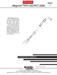
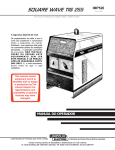
PRO-CUT 125
®
PLASMA CUTTING POWER SOURCE
IM491-B
October,1999
For use with machines having Code Numbers 10384 thru 10388
RETURN TO MAIN MENU
Safety Depends on You
Lincoln arc welding and cutting
equipment is designed and built
with safety in mind. However, your
overall safety can be increased by
proper installation ... and thoughtful operation on your part. DO
NOT INSTALL, OPERATE OR
REPAIR THIS EQUIPMENT
WITHOUT READING THIS
MANUAL AND THE SAFETY
PRECAUTIONS CONTAINED
THROUGHOUT. And, most
importantly, think before you act
and be careful.
R
OPERATOR’S MANUAL
• World's Leader in Welding and Cutting Products •
• Sales and Service through Subsidiaries and Distributors Worldwide •
Cleveland, Ohio 44117-1199 U.S.A. TEL: 216.481.8100 FAX: 216.486.1751 WEB SITE: www.lincolnelectric.com
WARNING
PLASMA CUTTING or GOUGING can be hazardous.
PROTECT YOURSELF AND OTHERS FROM POSSIBLE SERIOUS INJURY OR DEATH. KEEP CHILDREN
AWAY. PACEMAKER WEARERS SHOULD CONSULT WITH THEIR DOCTOR BEFORE OPERATING.
Read and understand the following safety highlights. For additional safety information it is strongly recommended that you purchase a copy of “Safety in Welding & Cutting - ANSI Standard Z49.1” from the American Welding Society, P.O. Box 351040,
Miami, Florida 33135 or CSA Standard W117.2.
BE SURE THAT ALL INSTALLATION, OPERATION, MAINTENANCE, AND REPAIR PROCEDURES ARE
PERFORMED ONLY BY QUALIFIED INDIVIDUALS.
ELECTRIC SHOCK can
kill.
FUMES AND GASES
can be dangerous.
1.a. The electrode and work (or ground) circuits
are electrically “hot” when the power source
is on. Do not touch these “hot” parts with
your bare skin or wet clothing. Wear dry,
hole-free gloves to insulate hands.
3.a. Plasma cutting or gouging may produce
fumes and gases hazardous to health.
Avoid breathing these fumes and
gases.When cutting or gouging, keep your
head out of the fumes. Use enough ventilation and/or exhaust at the arc to keep fumes and gases
away from the breathing zone. When cutting or gouging
on lead or cadmium plated steel and other metals or
coatings which produce highly toxic fumes keep exposure as low as possible and below Threshold Limit
Values (TLV) using local exhaust or mechanical ventilation. In confined spaces or in some circumstances, outdoors, a respirator may be required. Additional precautions are also required when cutting or gouging on galvanized steel.
3.b. Do not use plasma arc cutting or gouging in locations near
chlorinated hydrocarbon vapors coming from degreasing,
cleaning or spraying operations. The heat and rays of the arc
can react with solvent vapors to form phosgene, a highly
toxic gas, and other irritating products.
3.c. Gases used for plasma cutting and gouging can displace air
and cause injury or death. Always use enough ventilation,
especially in confined areas, to insure breathing air is safe.
3.d. Read and understand the manufacturer’s instructions for this
equipment and the consumables to be used, including the
material safety data sheet (MSDS) and follow your employer’s safety practices.
1.b. When the power source is operating voltages in excess of
250 volts are produced. This creates the potential for serious
electrical shock - potentially even fatal.
1.c. Insulate yourself from work and ground using dry insulation.
When cutting or gouging in damp locations, on metal framework such as floors, gratings or scaffolds and when in positions such as sitting or lying, make certain the insulation is
large enough to cover your full area of physical contact with
work and ground.
1.d. Always be sure the work cable makes a good electrical connection with the metal being cut or gouged. The connection
should be as close as possible to the area being cut or
gouged.
1.e. Ground the work or metal to be cut or gouged to a good electrical (earth) ground.
1.f. Maintain the plasma torch, cable and work clamp in good,
safe operating condition. Replace damaged insulation.
1.g. Never dip the torch in water for cooling or plasma cut or
gouge in or under water.
CUTTING SPARKS can
cause fire or explosion.
1.h. When working above floor level, protect yourself from a fall
should you get a shock.
1.i. Operate the pilot arc with caution. The pilot arc is capable of
burning the operator, others or even piercing safety clothing.
4.a..Remove fire hazards from the plasma cutting or gouging area. If this is not possible,
cover them to prevent the cutting or gouging
sparks from starting a fire. Remember that
welding sparks and hot materials from plasma cutting or
gouging can easily go through small cracks and openings to
adjacent areas. Avoid cutting or gouging near hydraulic lines.
Have a fire extinguisher readily available.
1.j. Also see Items 4c and 6.
4.b. Where compressed gases are to be used at the job site, special precautions should be used to prevent hazardous situations. Refer to “Safety in Welding and Cutting” (ANSI
Standard Z49.1) and the operating information for the equipment being used.
ARC RAYS can burn.
2.a. Use safety glasses and a shield with the proper filter and cover plates to protect your eyes
from sparks and the rays of the arc when performing or observing plasma arc cutting or
gouging. Glasses,headshield and filter lens
should conform to ANSI Z87. I standards.
4.c. When not cutting or gouging, make certain no part of the electrode circuit is touching the work or ground. Accidental contact can cause overheating and create a fire hazard.
4.d. Do not cut or gouge tanks, drums or containers until the proper steps have been taken to insure that such procedures will
not cause flammable or toxic vapors from substances inside.
They can cause an explosion even though they have been
“cleaned.” For information purchase “Recommended Safe
Practices for the Preparation for Welding and Cutting of
Containers and Piping That Have Held Hazardous
Substances”, AWS F4.1 from the American Welding Society
(see address above).
2.b. Use suitable clothing including gloves made from durable
flame-resistant material to protect your skin and that of your
helpers from the arc rays.
2.c. Protect other nearby personnel with suitable non-flammable
screening and/or warn them not to watch the arc nor expose
themselves to the arc rays or to hot spatter or metal.
4.e. Vent hollow castings or containers before heating, cutting or
gouging. They may explode.
4.f. Do nor fuel engine driven equipment near area where plasma
cutting or gouging.
Apr. ‘93
–2–
4.g. Sparks and spatter are thrown from the plasma arc. Wear
safety glasses, ear protection and oil free protective garments
such as leather gloves, heavy shirt, cuffless trousers, high
shoes and a cap over your hair. Wear ear plugs when cutting
or gouging out of position or in confined places. Always wear
safety glasses with side shields when in a cutting or gouging
area.
PLASMA ARC can injure.
7.a. Keep your body away from nozzle and
plasma arc.
7.b. Operate the pilot arc with caution. The pilot arc is capable of
burning the operator, others or even piercing safety clothing.
4.h. Connect the work cable to the work as close to the cutting or
gouging area as practical. Work cables connected to the building framework or other locations away from the cutting or
gouging area increase the possibility of the current passing
through lifting chains, crane cables or other alternate circuits.
This can create fire hazards or overheat lifting chains or
cables until they fail.
CYLINDER may explode
if damaged.
5.a. Use only compressed gas cylinders containing the correct gas for the process used
and properly operating regulators designed
for the gas and pressure used. All hoses,
fittings, etc. should be suitable for the application and maintained in good condition.
ELECTRIC AND MAGNETIC FIELDS
may be dangerous
5.b. Always keep cylinders in an upright position securely
chained to an undercarriage or fixed support.
8.a. Electric current flowing through any conductor causes localized Electric and
Magnetic Fields (EMF). Cutting or gouging
current creates EMF fields around torch
cables and cutting machines.
5.c. Cylinders should be located:
• Away from areas where they may be struck or subjected to
physical damage.
• A safe distance from plasma cutting or gouging, arc welding operations and any other source of heat, sparks,
or flame.
8.b. EMF fields may interfere with some pacemakers, so operators having a pacemaker should consult their physician
before cutting or gouging.
5.d. Never allow any part of the electrode, torch or any other
electrically “hot” parts to touch a cylinder.
8.c. Exposure to EMF fields during cutting or gouging may have
other health effects which are now not known.
5.e. Keep your head and face away from the cylinder valve outlet
when opening the cylinder valve.
8d. All operators should use the following procedures in order to
minimize exposure to EMF fields from the cutting or gouging
circuit:
5.f. Valve protection caps should always be in place and hand
tight except when the cylinder is in use or connected for
use.
8.d.1. Route the torch and work cables together - Secure
them with tape when possible.
5.g. Read and follow the instructions on compressed gas cylinders, associated equipment, and CGA publication P-l,
“Precautions for Safe Handling of Compressed Gases in
Cylinders,”available from the Compressed Gas Association
1235 Jefferson Davis Highway, Arlington, VA 22202.
8.d.2. Never coil the torch cable around your body.
8.d.3. Do not place your body between the torch and
work cables. If the torch cable is on your right side,
the work cable should also be on your right side.
FOR ELECTRICALLY
powered equipment.
8.d.4. Connect the work cable to the workpiece as close as
possible to the area being cut or gouged.
6.a. Turn off input power using the disconnect
switch at the fuse box before working on
the equipment.
8.d.5. Do not work next to cutting power source.
6.b. Install equipment in accordance with the U.S. National
Electrical Code, all local codes and the manufacturer’s recommendations.
6.c. Ground the equipment in accordance with the U.S. National
Electrical Code and the manufacturer’s recommendations.
–3–
Apr. ‘93
zones où l’on pique le laitier.
PRÉCAUTIONS DE SÛRETÉ
6. Eloigner les matériaux inflammables ou les recouvrir afin de
prévenir tout risque d’incendie dû aux étincelles.
Pour votre propre protection lire et observer toutes les instructions
et les précautions de sûreté specifiques qui parraissent dans ce
manuel aussi bien que les précautions de sûreté générales suivantes:
7. Quand on ne soude pas, poser la pince à une endroit isolé de
la masse. Un court-circuit accidental peut provoquer un échauffement et un risque d’incendie.
Sûreté Pour Soudage A L’Arc
1. Protegez-vous contre la secousse électrique:
8. S’assurer que la masse est connectée le plus prés possible de
la zone de travail qu’il est pratique de le faire. Si on place la
masse sur la charpente de la construction ou d’autres endroits
éloignés de la zone de travail, on augmente le risque de voir
passer le courant de soudage par les chaines de levage,
câbles de grue, ou autres circuits. Cela peut provoquer des
risques d’incendie ou d’echauffement des chaines et des
câbles jusqu’à ce qu’ils se rompent.
a. Les circuits à l’électrode et à la piéce sont sous tension
quand la machine à souder est en marche. Eviter toujours
tout contact entre les parties sous tension et la peau nue ou
les vétements mouillés. Porter des gants secs et sans trous
pour isoler les mains.
b. Faire trés attention de bien s’isoler de la masse quand on
soude dans des endroits humides, ou sur un plancher metallique ou des grilles metalliques, principalement dans
les positions assis ou couché pour lesquelles une grande
partie du corps peut être en contact avec la masse.
c. Maintenir le porte-électrode, la pince de masse, le câble de
soudage et la machine à souder en bon et sûr état defonctionnement.
d.Ne jamais plonger le porte-électrode dans l’eau pour le
refroidir.
e. Ne jamais toucher simultanément les parties sous tension
des porte-électrodes connectés à deux machines à souder
parce que la tension entre les deux pinces peut être le total
de la tension à vide des deux machines.
f. Si on utilise la machine à souder comme une source de
courant pour soudage semi-automatique, ces precautions
pour le porte-électrode s’applicuent aussi au pistolet de
soudage.
9. Assurer une ventilation suffisante dans la zone de soudage.
Ceci est particuliérement important pour le soudage de tôles
galvanisées plombées, ou cadmiées ou tout autre métal qui
produit des fumeés toxiques.
10. Ne pas souder en présence de vapeurs de chlore provenant
d’opérations de dégraissage, nettoyage ou pistolage. La
chaleur ou les rayons de l’arc peuvent réagir avec les vapeurs
du solvant pour produire du phosgéne (gas fortement toxique)
ou autres produits irritants.
11. Pour obtenir de plus amples renseignements sur la sûreté, voir
le code “Code for safety in welding and cutting” CSA Standard
W 117.2-1974.
2. Dans le cas de travail au dessus du niveau du sol, se protéger
contre les chutes dans le cas ou on recoit un choc. Ne jamais
enrouler le câble-électrode autour de n’importe quelle partie du
corps.
PRÉCAUTIONS DE SÛRETÉ POUR
LES MACHINES À SOUDER À
TRANSFORMATEUR ET À
REDRESSEUR
3. Un coup d’arc peut être plus sévère qu’un coup de soliel, donc:
a. Utiliser un bon masque avec un verre filtrant approprié ainsi
qu’un verre blanc afin de se protéger les yeux du rayonnement de l’arc et des projections quand on soude ou
quand on regarde l’arc.
b. Porter des vêtements convenables afin de protéger la peau
de soudeur et des aides contre le rayonnement de l‘arc.
1. Relier à la terre le chassis du poste conformement au code de
l’électricité et aux recommendations du fabricant. Le dispositif
de montage ou la piece à souder doit être branché à une
bonne mise à la terre.
c. Protéger l’autre personnel travaillant à proximité au
soudage à l’aide d’écrans appropriés et non-inflammables.
2. Autant que possible, I’installation et l’entretien du poste seront
effectués par un électricien qualifié.
4. Des gouttes de laitier en fusion sont émises de l’arc de
soudage. Se protéger avec des vêtements de protection libres
de l’huile, tels que les gants en cuir, chemise épaisse, pantalons sans revers, et chaussures montantes.
3. Avant de faires des travaux à l’interieur de poste, la debrancher
à l’interrupteur à la boite de fusibles.
5. Toujours porter des lunettes de sécurité dans la zone de
soudage. Utiliser des lunettes avec écrans lateraux dans les
4. Garder tous les couvercles et dispositifs de sûreté à leur place.
–4–
Mar. ‘93
TABLE OF CONTENTS
Page
Safety Precautions .............................................................................................................2-4
Introductory Information .......................................................................................................6
Specifications.......................................................................................................................7
Product Description..............................................................................................................8
Preheat Temperature for Plasma Cutting ............................................................................8
User Responsibility ..............................................................................................................8
Installation .........................................................................................................................9-11
Safety Precautions ........................................................................................................9
Location .........................................................................................................................9
High Frequency Interference Protection........................................................................9
Electrical Input Connection...........................................................................................10
Air Input Connections ...................................................................................................11
Output Connections......................................................................................................11
Torch Connection...................................................................................................11
Work Cable and Clamp Installation........................................................................11
Operating Instructions ......................................................................................................11-14
Sequence of events......................................................................................................11
Pilot Arc Discussion......................................................................................................12
Procedure Recommendations ......................................................................................12
General ..................................................................................................................12
Material Thickness below .75” (19mm) ..................................................................12
Expanded Metal .....................................................................................................13
Material Thickness above .75” (19mm)..................................................................13
Gouging .................................................................................................................13
In All Cases ............................................................................................................14
Suggestions for Extra Utility from the PRO-CUT System.............................................14
Maintenance Procedures ....................................................................................................15
Routine Maintenance....................................................................................................15
Troubleshooting Procedures......................................................................................15-22
Troubleshooting Guide ........................................................................................15-19
PRO-CUT 125 Status Lights Operating Modes...................................................20-21
Procedure for Replacing P.C. Boards ....................................................................22
Parts Lists.........................................................................................................................24-33
Input Supply Connection for Triple Voltage Machine..........................................................34
Cutting Torch Connection Diagram.....................................................................................35
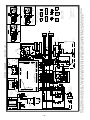
Wiring Diagram PRO-CUT 125...........................................................................................36
–5–
Thank You
for selecting a QUALITY product by Lincoln Electric. We want you
to take pride in operating this Lincoln Electric Company product
••• as much pride as we have in bringing this product to you!
Please Examine Carton and Equipment For Damage Immediately
When this equipment is shipped, title passes to the purchaser upon receipt by the carrier. Consequently, Claims
for material damaged in shipment must be made by the purchaser against the transportation company at the
time the shipment is received.
Please record your equipment identification information below for future reference. This information can be
found on your machine nameplate.
Model Name & Number _____________________________________
Code & Serial Number _____________________________________
Date of Purchase
_____________________________________
Whenever you request replacement parts for or information on this equipment always supply the information
you have recorded above.
Read this Operators Manual completely before attempting to use this equipment. Save this manual and keep it
handy for quick reference. Pay particular attention to the safety instructions we have provided for your protection.
The level of seriousness to be applied to each is explained below:
WARNING
This statement appears where the information must be followed exactly to avoid serious personal injury or
loss of life.
CAUTION
This statement appears where the information must be followed to avoid minor personal injury or damage to
this equipment.
–6–
SPECIFICATIONS
Type
K1394-* and K1395-*
K880-1[25Ft.(7.6m)Cable] & K880-2 [50Ft.(15.2m)Cable]
Magnum PCT125 Air Cooled Torch
Input Frequency
50 or 60 Hz, 3ø
Output Rating
125 Amps, 148 volts, 60% Duty Cycle
110 Amps, 140 volts, 80% Duty Cycle
100 Amps, 135 volts, 100% Duty Cycle
Pilot Current
Pilot Duty Cycle
Current Range
Maximum OCV@10% High Input
Normal OCV
Input Power
Standard Voltages
Current
26 amps
25% (20 seconds out of 80 seconds)
50-125 Amps
357
325
Idle Current
Idle Power
Power Factor @ Rated Load
Net Weight
w/25 ft. (7.6 m) Cable
w/50 ft. (15.2 m) Cable
Dimensions, H x W x D
4.5 amps @ 220V
0.7 kW Maximum
0.60
(includes lift bail and undercarriage)
230/460/3/50/60
101/49 @ 60%
95/44 @ 80%
88/40 @ 100%
220/380/440/3/50/60
102/59/51 @ 60%
87/54/45 @ 80%
81/49/42 @ 100%
480 lbs/218.2 kg
489 lbs/222.3 kg
35.6” x 19” x 22” (905mm x 483mm x 559mm)
* Several standard input voltages and options packages are available specified by type number.
–7–
575/3/60
40 @ 60%
33 @ 80%
32 @ 100%
PRODUCT DESCRIPTION
PREHEAT TEMPERATURE FOR
PLASMA CUTTING
The PRO-CUT™ 125 is a constant current, single
range, continuous control plasma cutting system. The
system is one of the most sophisticated on the
market. It provides excellent starting characteristics,
cutting visibility and arc stability. The torch has a
patented safety mechanism which insures that the
consumables are in place before cutting or gouging.
This is extremely important due to the high voltages
involved.
Preheat temperature control is recommended for optimum mechanical properties, crack resistance and
hardness control. This is particularly important on
high alloy steels and heat treated aluminum. Job conditions, prevailing codes, alloy level, and other considerations may also require preheat temperature control. The recommended minimum preheat temperature is a starting point. Higher temperatures may be
used as required by the job conditions and/or prevailing codes. If cracking or excessive hardness occurs
on the cut face, higher preheat temperature may be
required. The recommended minimum preheat temperature for plate thickness up to
1 1/4 inch is 70 (°F).
The PRO-CUT 125 comes with an air regulator,
coarse air filter, oil coalescing filter, and pressure
gauge. The machine comes with a 25 ft. torch cable
or a 50 ft. torch cable and a spare parts kit. The
undercarriage is built-in and the unit is shipped
assembled except for the handle. The machine is
capable of cutting with compressed air or nitrogen.
Nitrogen is used to cut aluminum and other nonferrous metals.
USER RESPONSIBILITY
Because design, fabrication, erection and cutting variables affect the results obtained in applying this type
of information, the serviceability of a product or structure is the responsibility of the user. Variations such
as plate chemistry, plate surface condition (oil, scale),
plate thickness, preheat, quench, gas type, gas flow
rate and equipment may produce results different than
those expected. Some adjustments to procedures
may be necessary to compensate for unique individual conditions. Test all procedures duplicating actual
field conditions.
The PRO-CUT is controlled by a microprocessorbased system. The machine performs rudimentary
self troubleshooting when started, which aids in field
servicing.
To enhance safety and protection, the 60 second
postflow period is monitored. During the first 12 seconds of postflow, the pilot arc may be initialized with a
single trigger pull. After 12 seconds, the trigger must
be pulled twice to start the pilot arc. The second trigger pull must follow the first within 1 second to initiate
the arc. This prevents accidental starting if the plasma
torch is resting in such a manner that the trigger is
depressed. The postflow time is reset only if the pilot
arc is initialized.
Special control circuitry detects when the nozzle is
touched to the workpiece. If the nozzle is touched to
the workpiece, the machine output is instantaneously
reduced which protects the consumables. When the
nozzle is removed form the workpiece, the output will
return to the set level. This feature protects the consumables from accidental damage when cutting at
high currents.
–8–
HIGH FREQUENCY INTERFERENCE
PROTECTION
INSTALLATION
SAFETY PRECAUTIONS
●
●
●
●
The PRO-CUT employs a solid state high frequency
torch starting circuit which drastically reduces high frequency emissions from the machine as compared with
spark gap type high frequency generators.
Read the safety precautions at the beginning of
this Operator's Manual before proceeding.
Only personnel that have read and understood this Operating Manual should install and
operate this equipment.
Machine must be connected to system ground per
any national, local or other applicable electrical
codes.
The power switch is to be in the “OFF” position
when connecting power cord to input power.
Radiated interference can develop, however, in the
following four ways:
WARNING
TURN THE INPUT POWER OFF USING THE DISCONNECT SWITCH AT THE FUSE BOX BEFORE
ATTEMPTING TO CONNECT THE INPUT POWER
LINES.
(1)
Direct interference radiated from the machine.
(2)
Direct interference radiated from the cutting
leads.
(3)
Direct interference radiated from feedback into
the power lines.
(4)
Interference from reradiation of “pickup” by
ungrounded metallic objects.
• Only qualified personnel should perform this installation.
Keeping these contributing factors in mind, installing
equipment per the following instructions should minimize problems.
• Turn the power switch on the PRO-CUT “off” before
connecting or disconnecting output cables.
(1)
• Connect the PRO-CUT grounding terminal located
on the side of the case back to a good electrical
earth ground.
------------------------------------------------------------------------
Keep the machine power supply lines as short as
possible.
(2) Keep the work and torch leads as short as possible and as close together as possible. Lengths
should not exceed 50’ (15.2 m). Tape the leads
together when practical.
LOCATION
Place the PRO-CUT where clean cooling air can
freely circulate in through the front intake and out
through the rear louvers. Dirt, dust or any foreign
material that can be drawn into the machine should be
kept at a minimum. Failure to observe these precautions can result in excessive operating temperatures
and nuisance shutdown of the machine. Before planning the installation, read the section entitled “High
Frequency Interference Protection”.
(3)
Be sure the torch and work cable rubber coverings are free of cuts and cracks that allow high
frequency leakage.
A source of clean, dry compressed air or nitrogen
must be supplied to the PRO-CUT. Oil in the air is a
severe problem and must be avoided. The supply
pressure must be between 80 and 150 psi (551 and
1032 kPa). The flow rate is approximately 8.0 cfm
(225 l/min.). Failure to observe these precautions
could result in excessive operating temperatures or
damage to the torch.
NOTE: The machine frame MUST also be grounded see paragraph under “Input Connection”. The
work terminal ground does not ground the
machine frame.
(4) Keep the torch in good repair and all connections
tight to reduce high frequency leakage.
(5) Keep all access panels and covers securely in
place
(6)
When the machine is enclosed in a metal building, several good earth driven electrical grounds
around the periphery of the building
are recommended.
Failure to observe these recommended installation
procedures may cause radio or TV interference problems and result in unsatisfactory cutting or gouging
performance resulting from lost high frequency power.
–9–
ELECTRICAL INPUT CONNECTION
WARNING
WARNING
ELECTRIC SHOCK can kill.
• Make certain that the input power
is electrically disconnected before
removing the screws that hold the
removable rear panel in place.
------------------------------------------------------------
ELECTRIC SHOCK can kill.
• Disconnect input power before
proceeding.
• Have a qualified electrician make
the input connections.
• Be sure the voltage, phase and frequency
of the input power is as specified on the
machine nameplate.
------------------------------------------------------------
Have a qualified electrician connect the input leads to
“U”, “V” and “W” of the reconnect panel in accordance
with the U.S. National Electrical Code, all local codes
and the connection diagram located on the inside of
the cover.
Before starting the installation, check with the local
power company if there is any question about whether
your power supply is adequate for the voltage,
amperes, phase and frequency specified on the rear
machine nameplate. Also be sure the planned installation will meet the U.S. National Electrical Code and
local code requirements.
The frame of the machine must be grounded. A
ground terminal marked with the symbol
located at
the left side of the input box is provided for this purpose. See the U.S. National Electrical Code for details
on proper grounding methods. Follow other grounding
instructions per the paragraph under “High Frequency
Interference Protection”.
Use a three phase power supply fused with the recommended super lag fuses. Choose an input and
grounding wire size according to local codes or use
the table below. “Delay type” circuit breakers (also
called “inverse time” or “thermal/magnetic”; which
have a delay in tripping action that decreases as the
magnitude of the current increases) may be used in
place of fuses. Using fuses or circuit breakers smaller
than recommended may result in “nuisance” tripping
from machine inrush currents even if not cutting or
gouging at high currents.
On triple voltage input machines, be sure the reconnect panel is connected per Figure 1 in the back of
this manual, for the voltage being supplied to the
machine.
CAUTION
• Failure to follow these instructions can cause immediate failure of machine components.
-----------------------------------------------------------------------The PRO-CUT is shipped connected for the highest
nameplate input voltage. Reconnect the power straps
to their respective terminals corresponding to the input
voltage used.
Models that have multiple input voltages specified on
the rear nameplate (e.g. 230/460) are shipped connected for the higher voltage. If the machine is to be
operated on the lower voltage, it must be reconnected
according to the instructions on the inside of the
removable panel in the center of the rear panel.
Electrical supply lines enter the machine next to the
removable panel.
RECOMMENDED WIRE SIZE FOR PRO-CUT INPUT CONNECTIONS
Based on 1993 U.S. National Electric Code
Wire Size
(Copper, 75°C)
Input
Voltage / Hz.
3 Input Wires
1 Grounding Wire
Fuse Size
230/60
#3 (25mm2)
#8 (10mm2)
125Amp
460/60
#8 (10mm2)
#8 (10mm2)
60Amp
220/50/60
#3 (25mm2)
#8 (10mm2)
125Amp
380/50/60
#6 (16mm2)
#8 (10mm2)
70Amp
440/50/60
#8 (10mm2)
#8 (10mm2)
60Amp
– 10 –
AIR INPUT CONNECTIONS
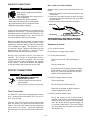
Work Cable and Clamp Installation
WARNING
Attach the work clamp to the work cable per the following:
CYLINDER may explode if damaged
• Keep cylinder upright and chained to a
fixed support.
• Keep cylinder away from areas where it
may be damaged.
• Never lift equipment with cylinder attached.
• Never allow the cutting torch to touch cylinder.
• Keep cylinder away from live electrical circuits.
• Maximum inlet pressure 150 psig.
------------------------------------------------------------------------
1. Unplug the machine or turn the power switch to the
“Off” position.
2. Insert the work cable terminal lug with the larger
hole through the strain relief hole in the work clamp
as shown below.
3. Fasten securely with the bolt and nut provided.
Work cable
A source of clean compressed air or nitrogen must be
supplied to the PRO-CUT. The supply pressure must
be between 80 and 150 psi (551 and 1034 kPa). The
flow rate is approximately 8.0 cfm. Oil in the air is a
very severe problem and must be avoided.
Work clamp
OPERATING INSTRUCTIONS
Remove the plastic thread protector from the regulator
input port (located on the back of the machine). Use a
suitable gas connection fitting to make the connection
to the available air supply. The input port is a 1/4”
(6.3 mm) NPT thread. Tighten the air fitting to prevent
leakage but do not overtighten. The use of Teflon
tape to seal the connection is recommended.
Sequence of events:
A. Turn on the line power.
B. Connect the air supply to the machine.
C. Turn the power switch on.
Nitrogen from cylinders may be used with this
machine. The cylinder of nitrogen gas must be
equipped with a pressure regulator. No more than
150 psi (1034 kPa) may be supplied to the regulator
on the machine. Install a hose between the regulator
on the gas cylinder and the gas inlet on the cutter.
-The green “Power On” LED should begin to
glow.
-The fan should start.
-If the “Safety” LED is glowing, push the “Safety
Reset” button. If there is no problem, the LED
will go off. If there is a problem, refer to Step F
and the Troubleshooting Guide.
OUTPUT CONNECTIONS
WARNING
HIGH FREQUENCY SHOCK CAN
CAUSE INJURY OR FALL.
• Keep the cutting torch and cables in
good condition.
• Secure yourself in position to avoid a fall.
----------------------------------------------------------------------------
D. Set the Purge/Run switch to Purge.
-The air should start.
-The “Air Pressure” LED should be lit.
-Adjust the air regulator so that the pressure
gauge reads 60 psi (414 kPa).
Torch Connection
E. Set the Purge/Run switch to Run.
The PRO-CUT comes factory equipped with a cutting
torch. Cutting torches come with a 25 ft. (7.6 m) or a
50 ft. (15.2 m) cable.
-The air will continue to run for 60 seconds of
postflow. If the trigger is activated within the first
twelve seconds, the pilot arc will immediately
start. After twelve seconds, a double trigger pull
is required to start the arc. The second trigger
pull must follow the first within one second to
start the pilot arc.
Pictures of the torch and the required replacement
parts are shown in the parts lists in the back of this
manual. The ends of the cable to be connected to the
power source are unique. Follow the applicable
instructions given in Figure 2 in the back of this manual.
– 11 –
F. When ready to cut, place the work lead on the
piece to be cut, place the torch near the work, make
certain all safety precautions have been taken and
pull the trigger.
Pilot Arc Discussion:
The PRO-CUT has a smooth, continuous pilot arc.
The pilot arc is only a means of transferring the arc to
the workpiece for cutting. Repeated pilot arc starts, in
rapid succession, are not recommended, as this will
reduce consumable life. Occasionally, the pilot arc
may sputter or start intermittently. This is aggravated
when the consumables are worn or the air pressure is
too high. Keep in mind that the pilot arc is designed to
transfer the arc to the workpiece and not for numerous
starts without cutting.
-The air will flow for a preflow time of 2 seconds
and the pilot arc will start. (This is true unless
the machine is in postflow, then the preflow time
is skipped.)
-The “Output ON” LED will light.
-The pilot arc will run for 1.8 seconds and shut off
unless the plasma is brought in contact with the
work and the arc is transferred.
Procedure Recommendations
When properly used, plasma arc cutting or gouging is
a very economical process. Improper use will result in
a very high operating cost.
-When the arc is transferred, cutting begins.
When finished cutting, release the trigger.
G. When the trigger is released, the arc will stop.
If the nozzle is touched to the work while cutting, the
output current will be reduced to minimum until the
nozzle is removed from the work.
-The air will continue to run for 60 seconds of
postflow. If the trigger is activated within the
first 12 seconds, the pilot arc will immediately
restart. After twelve seconds, a double trigger
pull is required to start the arc. The second trigger pull must follow the first within one second
to start the pilot arc.
General
• Follow safety precautions as printed inside the
operating manual and on the machine.
H. If the “Safety” LED lights at any time, check the following:
• Either the S19972 standoff guide or S19973
and S19974 contact attachments are recommended for all cutting applications to protect the
torch from dross and improper arcing conditions.
WARNING
ELECTRIC SHOCK CAN KILL.
• Turn off machine at the disconnect
switch at the back of the machine before
tightening, cleaning or replacing consumables.
------------------------------------------------------------------------
• Use proper cutting or gouging procedures
referred to in procedures guideline.
Material thickness below .75 (19mm):
• Check the assembly of the torch consumables.
If they are not properly in place then machine
will not start.
Output set below mid-range.
• Do not allow the torch cable or body to contact
hot surfaces.
• Check the conditions of the inside of the nozzle.
If debris has collected, scrape it out with a piece
of sturdy wire or a suitable drill bit. Refer
to“Suggestions for Extra Utility from the PROCUT system”.
• The best cut quality is obtained by reducing the
current to a level that is adequate for the maximum travel speed.
• Aluminum, copper and other nonferrous metals
typically require more current than the same
thickness of steel.
• After the problem is found, reset the machine by
pressing the “Safety Reset” button. (It is possible for electrical noise to trip the safety circuit on
rare occasions. This should not be a regular
occurrence.)
• For thickness below .75” (19mm) use an
S19961-2 nozzle (1.4mm dia. orifice). The
S19972 standoff guide should be set in the lowest position for maximum standoff.
• If the machine does not reset or continues to
trip, consult the Troubleshooting Section of this
manual.
– 12 –
Expanded Metal:
• Where possible, start the cut from the edge of
the workpiece.
Output set near mid-range.
• Keep moving! A steady speed is necessary.
Do not pause.
• Cut it as you would light gauge sheet metal.
• Expanded metal is pilot arc intensive. After
about 30 seconds of cutting, the pilot arc will
change from a bright continuous arc to a discontinuous one which will sputter slightly. It will stay
in this mode as long as metal has been cut in
the previous 5 seconds. If metal is not cut in the
previous 5 seconds, the arc will shut off and the
machine will go into postflow.
• Do not allow the torch cable or body to contact
hot surfaces.
• For thickness between .75” (19mm) and 1.00”
(25.4mm), use an S19961-4 nozzle (1.9mm dia.
orifice). The S19972 standoff guide should be in
the lowest position for maximum standoff.
• For thickness above 1.00” (25.4mm), use an
S19961-4 nozzle (1.9mm dia. orifice). The
S19972 standoff guide should be in the lowest
position for maximum standoff.
•If the trigger is continuously pressed and
released to obtain the bright pilot arc for long
periods of time, the machine will go into pilot arc
duty cycle limit. This is a 20 seconds out of 80
seconds pilot duty cycle. The pilot arc is disabled in the limit period. Pilot arc duty cycle
limit is indicated by alternately flashing “OUTPUT ON” and “MALFUNCTION” LED’s.
Gouging:
• Placing a thin piece of scrap sheet metal above
the area to be cut and cutting through both can
make the job easier.
Output set to maximum.
• Use a gouging nozzle S19961-5. The pilot arc
may sputter while gouging, but this is normal.
• Do not allow cable or body to contact hot surface.
• Use the S19975 gouging attachment in the lowest position for maximum standoff.
• Bring the torch slowly towards the work at about
a 30° angle as if piercing the plate. Blow the
molten metal away from the torch.
Material Thickness above .75” (19mm):
• Do not touch the nozzle to the work.
Output set above mid-range.
• To obtain deeper penetration when gouging,
lower the flowing air pressure to 50 psi. To
obtain shallower penetration, raise the flowing
air pressure to 70 psi.
• The best quality and consumable life will be
obtained by holding the torch nozzle off the surface about 1/4” (6.4mm). Do not touch the nozzle to the work or carry a long arc.
• This process will blow a lot of molten metal and
dross. BE CAREFUL! Blow the dross away
from the torch, away from the operator and
away from flammable objects.
• Use either S19972 standoff guide or S19973
and S19974 contact attachments to protect the
torch. The only reason not to use these are in
special tight corners. Always hold at least a 1/4”
(6.4mm) standoff in those situations.
• Do not allow the torch cable or body to contact
hot surfaces.
• Set the current to the minimum necessary to
make the cut.
• Performance is similar to air carbon arc gouging
with a 1/8” (3.2mm) carbon electrode.
• Pierce the plate by slowly lowering the torch
onto it at an angle of about 30° to blow the
dross away from the torch tip and slowly rotate
the torch to a vertical position as the arc
becomes deeper.
– 13 –
• The PRO-CUT is capable of operation with a 50
ft. (15.2 m) plasma torch. Pilot arc operation
may be slightly degraded with this torch
installed. Sputtering may occur after the pilot
arc is established and occasionally the pilot arc
may not light after the trigger is depressed.
Neither cutting performance nor machine reliability will be lessened by this condition. Keep in
mind that the condition of the consumables and
air pressure level have a large impact on pilot
arc ignition.
In All Cases:
• Do not pause when cutting or gouging the
metal. This is not necessary and causes operational difficulty. Pausing at the edge of the workpiece causes poor consumable life and erratic
operation.
• Always position the torch in the best way to
keep dross and hot air from burning back into it.
• Do not carry a long arc. This may trip the safety
or fault circuits and wears consumables rapidly.
WARNING
• Always hold a 1/4” standoff while cutting.
ELECTRIC SHOCK CAN KILL.
• Use the proper machine setting. Setting the
machine to maximum output will not produce
the best cutting performance in most situations.
Turn off machine at the disconnect switch on the front
of the machine before tightening, cleaning or replacing
consumables.
------------------------------------------------------------------------
• Use proper cutting or gouging procedures
referred to in Procedures Guideline.
• The PRO-CUT will cut with consumables that
are worn considerably. Many competitive systems require replacement consumables long
before a PRO-CUT system does. This is
because of the solid state current regulation that
the PRO-CUT has. Also, the safety reset circuit
provides a means of extending nozzle life.
Sometimes a small piece of material “spits” from
the electrode and bridges the gap between the
nozzle and the electrode. In a competitive unit,
this would often result in the destruction of the
electrode and nozzle due to overheating. This
will result in the tripping of the PRO-CUT safety
circuit. When this happens, turn the power off,
remove the nozzle and scrape any debris from
its inside cavity with a piece of sturdy wire or a
suitable drill bit. Replace the nozzle, turn on the
power and continue cutting.
• Use the nozzle with the largest orifice size that
gives an acceptable cut. This will improve parts
life. Never use the 1.1 mm dia. or 1.4 mm dia.
nozzles at outputs above the yellow range.
• The electrode should be finger tight for a snug
fit. It should not be torqued any more than 38
inch pounds. DO NOT USE PLIERS TO OVERTIGHTEN THE ELECTRODE.
• Always allow the 62 second postflow time to
elapse before attempting to change the electrode. Failure to do so may cause severe damage to the torch head.
Suggestions for Extra Utility from the
PRO-CUT System:
• Gouging nozzles may be made from worn cutting nozzles by drilling the orifice out to .125”
(3.2mm). Use a 1/8 or #31 drill bit. Take care to
center the hole and be careful because the copper nozzle may seize to the drill bit.
• If it becomes absolutely necessary to cut
through a very thick section, the air flow at the
regulator on the back of the machine may be
lowered to get a better result. If it is taken too
low, the power source will trip off until the pressure is raised back to about 45 psi (311 kPa). It
is not wise to operate in this manner for long
periods of time because the consumable life is
severely shortened.
• Use of the nozzle with the largest orifice size
that produces acceptable cutting results will
maximize consumable life. Smaller orifice sizes
constrict the arc more, raising the energy density and the temperature. Larger orifice sizes
have the opposite effect. Small orifice nozzles
run hotter and wear faster than large orifice nozzles but produce a finer cut with less kerf width.
There is a certain current where each orifice
size becomes unstable because it runs too hot.
Never use the smallest .043 (1.1 mm) orifice
size at outputs above the yellow range because
it will be quickly destroyed.
• In some cases where moderate or thin sections
are being cut, higher air pressure may give better consumable life. At pressures about 70 psi
(482 kPa), the pilot arc may sputter. This may
be an annoyance but it will not damage the
torch or power source. 60 psi (414kPa) is the
minimum recommended pressure to provide
proper cooling in all situations. Feel free to
experiment with higher pressures not to exceed
150 psi (1034 kPa).
– 14 –
MAINTENANCE PROCEDURES
TROUBLESHOOTING PROCEDURES
WARNING
WARNING
ELECTRIC SHOCK CAN KILL.
ELECTRIC SHOCK CAN KILL.
BEFORE PERFORMING ANY MAINTENANCE THAT REQUIRES OPENING
THE CASE OF THE POWER SOURCE:
BEFORE PERFORMING ANY MAINTENANCE THAT REQUIRES OPENING
THE CASE OF THE POWER SOURCE:
• Disconnect input power to this machine at the
Disconnect switch.
• Disconnect input power to this machine at the
Disconnect switch.
• Do not touch electrically live parts or internal wiring.
• Do not touch electrically live parts or internal wiring.
• Only qualified personnel should service this
machine.
------------------------------------------------------------------------
• Only qualified personnel should service this
machine.
------------------------------------------------------------------------
ROUTINE MAINTENANCE
HOW TO USE THIS GUIDE: Carefully read through
each applicable section listed on the following pages.
Remember that most problems are caused by improper setup, such as switch settings, control settings, etc.
1.
Keep the cutting or gouging area and the area
around the machine clean and free of combustible materials. No debris should be allowed
to collect which could obstruct air flow to the
machine.
2.
Every few months, blow the dust off the air
intakes and louvers with compressed air.
3.
Check the air regulator filters to be sure they do
not become clogged. The first stage of the air
filter on the machine is self draining and will
stop most of the water in the air line. The second stage of the filter is also self draining and
will stop almost all of the oil in the line as well as
particulate matter. Both stages will drain automatically when the flow rate changes rapidly.
4.
Check the filter elements every several months
to see if they are clogged (weekly in very dirty
environments). Replace if necessary.
5.
Inspect the cable periodically for any slits or
puncture marks in the cable jacket. Replace if
necessary. Check to make sure that nothing is
crushing the cable and blocking the flow of air
through the air tube inside. Also, check for
kinks in the cable periodically and relieve any so
as not to restrict the flow of air to the torch.
If you believe the set up is correct and the trouble still
exists, first check for the obvious: input power, blown
fuses, loose PC board connectors, broken wires and
the like. The sections listed on the following pages
are intended to help you find the less obvious sources
of trouble.
TROUBLESHOOTING GUIDE
Visual Inspection
Clean interior of machine with a low pressure
airstream. Make a thorough inspection of all components. Look for signs of overheating, broken leads or
other obvious problems. Many problems can be
uncovered with a good visual inspection.
WARNING
ELECTRICAL SHOCK CAN KILL.
Turn off machine at the disconnect switch at the back
of the machine before tightening, cleaning or replacing
consumables.
-----------------------------------------------------------------------Change consumables as required.
After the visual inspection proceed to the proper
symptom section of this guide for necessary checks to
perform.
– 15 –
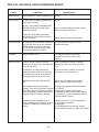
SYMPTOM
CHECK
No LED’s light when the power switch is turned on.
The “MACHINE ON” LED is lit, but there is no
response when the trigger is pulled.
– 16 –
1.
Check the input power to be sure it is on.
2.
Check the power line fuses and machine
connection.
3.
Replace line switch.
1.
Check the “SAFETY” LED. If it is lit, check the
torch consumables and press the “SAFETY
RESET” button.
2.
Check the air supply to the machine. If the air
does not flow, the machine will not start.
3.
Check the operation of the air solenoid by
switching the machine to “PURGE”. If the
pressure is sufficient, the air should begin to
flow and the “AIR PRESSURE” LED should
turn on. Return to “RUN” mode. If air does not
flow, check the solenoid by applying 115 VAC to
its input leads. If it is not bad, replace PC board.
4.
Low air pressure also results in a “no start”
condition. “AIR PRESSURE” LED must be lit
when air is flowing.
5.
12 seconds, or more, of postflow time has
elapsed and a double trigger pull is required to
start the pilot arc. The second trigger pull must
follow the first within 1 second to start the pilot
arc.
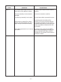
SYMPTOM
CHECK
The air begins to flow, the “OUTPUT ON” LED lights
for a brief period, but no arc is established.
1.
Check the torch consumables to be sure they
are in tight, not dirty or greasy, and in good
shape. Replace the consumables if necessary.
2.
Check that CR2 engages.
3.
Blow off the components in the upper compartment with compressed air.
4.
Check pilot to 391 for 1.5 ohm resistance.
5.
Check both 3 ohm 300 watt resistors.
6.
Replace Control PC board.
1.
Check the torch consumables to be sure they
are tight, not dirty or greasy and in good shape.
Replace if necessary.
2.
Check air supply for oil or a great deal of water.
If there is oil or a great deal of water, the air
must be filtered or the machine switched to
nitrogen or bottled air.
3.
Check air pressure. It should be set to 60 psi
(414 kPa) while air is flowing.
The “THERMAL” LED is lit. The “MALFUNCTION”
LED is blinking.
1.
The machine is overheated. Allow it to cool and
reset. The air intakes of the machine must not
be blocked, or this will become a nuisance.
Machine will cool much faster if left on with
output off.
The “MALFUNCTION” LED is blinking two short
flashes in close succession followed by a one second off
period.
1.
The torch connected to the machine is not
connected properly or has been damaged.
Check all connections and look for sign of
damage to the assembly.
2.
The connected torch is not designed for use
with this machine, see Specifications Summary
for listing of valid torches for this machine.
The arc starts but sputters badly.
– 17 –
SYMPTOM
CHECK
The “MALFUNCTION” LED is lit.
1.
The FAULT circuit monitors the torch to see if it is
shorted as well as internal machine failures.
2.
Check the torch consumables to see if they are
melted together or are simply touching each
other. Tighten, clean or replace. See
“Suggestions for Extra Utility from the PRO-CUT
System”.
3.
Check the torch cable to see if it is cut or
punctured. Replace.
4.
Turn off the machine and turn it back on. If the
“FAULT” LED will not stay off when you
try to cut again and there is no problem with the
torch, then something has failed in the machine
and the machine should not be left on.
4a. Check electrode to pilot for short.
4b. Check the SCR board. Replace if bad.
4c. Check operation of contactors. Replace if bad.
5.
Replace Control PC board.
Alternating “AIR/MALFUNCTION” LED lights
1.
Replace Control PC board.
Air pressure cannot be set to 60 psi (414 kPa) or the
machine cuts poorly through thick sections.
1.
Watch the pressure gauge during pilot mode.
The air pressure should start as 60 psi (414 kPa)
and be reduced significantly when the trigger is
pulled. If not, then there is a problem with the
solenoid assembly.
– 18 –
SYMPTOM
CHECK
The “SAFETY” LED is lit.
1.
The machine will not operate. The machine
senses that the shield cup is not in place, or the
operators could be exposed to dangerous
voltages if the machine were allowed to operate.
2.
Check the shield cup to be sure it is tightly in place.
3.
Check the torch consumables to see if they are
melted together or are simply touching each
other. Tighten, clean or replace. See
“Suggestions for Extra Utility from the Pro-Cut
System”.
4.
Check the torch cable to see if it is cut or
punctured. Replace.
5.
Check to see that the torch is hooked to the
machine properly.
6.
Push the ‘SAFETY RESET” button, the LED
should go out.
7.
This circuit rarely trips on power up or because
of noise. If the circuit can be reset, it is OK to
continue operation.
8.
Replace Control PC board, as this is a
safety problem.
The “OUTPUT ON” and “MALFUNCTION” LED’s
blink in alternating order.
1.
The pilot arc duty cycle has been exceeded.
The machine will cool down and the lights will
quit blinking in about 10 seconds. The pilot arc
is limited to 20 out of 80 seconds except in
special circumstances such as cutting
expanded metal. (See the section on expanded
metal in the Operating Section.)
Airflow will not shut off.
1.
Check harness 1J7 (332) and 3J7 (333) 24VAC
auxiliary supply.
2.
Replace Control PC board.
1.
Check CR1.
2.
230 VAC across CR1.
3.
250V SCR PC board positive/negative
4.
Check across 31/32 for 110 VAC.
5.
Replace Control PC board.
No OCV when 2 and 4 are closed.
– 19 –
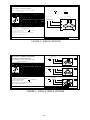
PRO-CUT 125 STATUS LIGHTS OPERATING MODES
STATUS
LIGHTS
CONDITION
SUGGESTIONS
MACHINE ON
Should always be on when machine is on. Normal
OUTPUT ON
On when there is voltage potential at the
torch (cutting or pilot).
Normal
OUTPUT ON is blinking alternately with
AIR PRESSURE when power is first
applied to machine.
There is a problem with the microprocessor,
replace the Control PC board.
If OUTPUT ON is blinking alternately
with MALFUNCTION, the pilot arc duty
cycle is exceeded.
Wait for machine lights to stop blinking.
AIR PRESSURE
On whenever the air pressure is above 45 Normal conditions are purge, preflow,
psi (311 kPa), there is an error condition
postflow and cutting.
mentioned above where air will turn on.
The air will turn on for a brief time when
power is first applied to machine.
THERMAL
Should normally be off.
If on, wait for machine to cool down.
Machine will cool faster if left on with
output off.
MALFUNCTION
Light on. At end of preflow, machine
checks to see if the torch is shorted and if
it can fire the SCR’s.
Check consumables, replace as needed.
Check torch cable to see if it is punctured
or cut.
Light blinking. If cutting tried with air
pressure less than 45 psi (311 kPa) then
the machine will wait for air pressure to
become greater than 45 psi (311 kPa).
No air connected to machine, air pressure
set too low, or air leak in system.
Light blinking alternately with OUTPUT
ON.
Pilot arc duty cycle has been exceeded.
Wait for machine lights to stop blinking.
Light started blinking during cutting or
gouging. There is an overcurrent condition
caused by a surge of current the machine
was not designed to handle. Release the
trigger and resume cutting or gouging.
If cutting or gouging with standoff more than
1/4” (6.4mm)
at high range of machine and nozzle is
accidentally touched to work, shorten stickout,
or use drag cup. Check consumables to see if
electrode melted to nozzle.
Light blinking with THERMAL light on.
Light is blinking two short flashes in close
succession followed by one second off
period.
Wait for machine to cool. Torch assembly is:
1. Not connected properly.
2. Damaged
3. Not designed for use with this machine.
Check connections; repair or replace as needed.
– 20 –
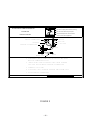
STATUS
LIGHTS
SAFETY
CONDITION
SUGGESTIONS
It is possible that this light could turn on
when power is first applied to machine.
If machine can be reset, it is OK to continue
operation.
The torch assembly is misconnected or
damaged.
Check torch connection to machine.
The shield cup assembly is not in place.
Securely fasten shield cup assembly in place.
While cutting or gouging if the voltage
between the nozzle and the work is too
high, it will put the machine into safety.
If the cable is punctured or cut, it can trip
the SAFETY
– 21 –
By pressing reset, the machine will be
functional. This occurs most often when the
consumables are wearing out. By removing
the hafnium that builds up on the inside of the
nozzle, it is possible to extend the life of the
consumables.
By pressing reset, it will clear the SAFETY.
When cutting is tried again, the machine will
either go into MALFUNCTION or SAFETY;
until that time, the machine will not indicate a
malfunction condition.
PROCEDURE FOR REPLACING PC BOARDS
WARNING
ELECTRIC SHOCK CAN KILL.
BEFORE PERFORMING ANY MAINTENANCE THAT REQUIRES OPENING
THE CASE OF THE POWER SOURCE:
• Disconnect input power to this machine at the
Disconnect switch.
• Do not touch electrically live parts or internal wiring.
• Only qualified personnel should service this
machine.
-----------------------------------------------------------------------Before replacing a PC board which is suspected of
being defective, visually inspect the PC board in question for any damage to any of its components and
conductors on the back of the board.
If there is no visible damage to the PC board, install a
new one and see if this remedies the problem. If the
problem is remedied, reinstall the old PC board to see
if the problem still exists. If it does no longer exist
with the old PC board:
1. Check the PC board harness conductor pins for
corrosion, contamination or looseness.
2.
Check leads in the plug harness for loose or
intermittent connection.
If PC board is visibly damaged electrically (components burned, copper traces opened or damaged),
before possibly subjecting the new PC board to the
same cause of failure, check for possible shorts,
opens or grounds caused by:
1. Frayed or pinched lead insulation.
2. Poor lead termination, such as a poor contact or
a short to adjacent connection or surface.
3. Two or more leads shorted together.
4. Foreign matter or interference behind the PC
boards.
If PC board is visibly damaged mechanically (such as
a part vibrated off or was crushed), inspect for cause,
then remedy before installing a replacement PC
board.
If there is damage to the PC board and if replacing PC
board corrects problem, return it to the local Lincoln
Electric Field Service Shop.
– 22 –
NOTES
– 23 –
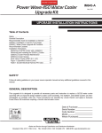
PCT 125 AMP PLASMA TORCH
Parts List P-210-C
2
3
2
7
4
9
5
12
6
1
11
13
10
2-10-92
– 24 –
PCT 125 AMP PLASMA TORCH
Item
1
1
2
*
*
3
*
*
4
5
*
*
*
*
6
7
9
10
11
12
13
*
Description
Mag PCT-125 Torch & Cable (25’)
Mag PCT-125 Torch & Cable (50’)
Cable Asbly (25’)
Cable Asbly (50’)
Handle Repair Kit
Handle (LH), Includes:
Handle Nut
Handle (RH), Includes:
Pan Handle Screw (#6-32 x .75)
Torch Head
O-Ring, Shield Cup
O-Ring, Handle
Electrode
Nozzle:
Cutting .055” (1.4mm) Orifice
Cutting .067” (1.7mm) Orifice
Cutting .075” (1.9mm) Orifice
Gouging .118” (3.0mm) Orifice
Shield Cup Asbly
Trigger Asbly
Swirl Ring
Standoff Guide
Gouging Attachment
Contact Cutting Insulator
Contact Cutting Attachment
Tool Box
Options
Spare Parts Kit:
Cutting .055” (1.4mm) Orifice
Cutting .067” (1.7mm) Orifice
Cutting .075” (1.9mm) Orifice
Gouging .118” (3.0mm) Orifice
Electrode
Swirl Ring
O-Ring, Shield Ring
Standoff Guide
Part
No.
Parts List P-210-C.1
No.
Req’d.
K880-1
K880-2
L9371-1
L9371-2
S21087
1
1
1
1
1
S18773
4
S18825-1
L8680
L8680-B
L8680-A
S19962
4
1
1
1
1
S19961-2
S19961-3
S19961-4
S19961-5
S19964
S18932
S19963
S19972
S19975
S19973
S19974
S19576-2
1
1
1
1
1
1
1
1
1
1
2
1
K881-1
S19961-2
S19961-3
S19961-4
S19961-5
S19962
S19963
L8680-B
S19972
1
3
5
3
2
5
2
3
3
2-10-92
– 25 –
Parts List P-207-C
GENERAL ASSEMBLY
PRO-CUT 125 THREE PHASE
Drop in photos from P-207-C
parts page.
– 26 –
GENERAL ASSEMBLY
PRO-CUT 125 THREE PHASE
Item
1
2
3
*
*
*
4
5
*
*
6
*
7
*
8
*
*
9
*
10
11
*
*
12
*
*
13
*
*
*
*
14
*
*
14
15A
*
*
15B
*
*
16
*
*
17
*
*
*
*
18
*
*
*
*
Description
Base
Base Support
Foot
Thread Forming Screw
Caster
Thread Forming Screw
Axle
Wheel
Plain Washer
Cotter Pin
Case Front Asbly
Self Tapping Screw
Left Case Side (Not Shown)
Self Tapping Screw
Right Case Side (Not Shown)
Self Tapping Screw
Access Door
Roof (Not Shown)
Self Tapping Screw
Cover Seal (Not Shown)
Case Back Asbly
Self Tapping Screw
Access Door
Regulator & Filter Asbly
Self Tapping Screw
Mounting Bracket
Solenoid Asbly
Sems Screw
Flex Tube (Short)
Flex Tube (Medium)
Flex Tube (Long)
Transformer & Lift Bail Asbly (Dual & Triple Voltage)
Transformer Asbly (Dual & Triple Voltage)
Lift Bail
Transformer & Lift Bail Asbly (Single Voltage)
Resistor (R3)
Self Tapping Screw
Resistor Mounting Bracket (Set)
Resistor (R2, R5)
Self Tapping Screw
Resistor Mig Bracket (Set)
Resistor
Round Head Screw
Insulator
Choke & Right Wheel Well Asbly
Choke Asbly
Right Wheel Well
Thread Forming Screw
Self Tapping Screw
Choke & Left Wheel Well Asbly
Choke Asbly
Left Wheel Well
Thread Forming Screw
Self Tapping Screw
Part
No.
L8473
L8472
L8284
S9225-26
S11124-8
S9225-28
T6988-22
S17073-4
S9262-142
S10750-1
See P-184-D
S8025-65
L7745-1
S8025-65
L7745-2
S8025-65
S18763
L7662
S8025-65
S12934
See P-207-D
S8025-65
M16380
See P-184-E
S8025-65
S18579
See P-207-E
T10082-27
T10642-192
T10642-193
T10642-194
S20942
L9318
S10227-47
L9445
S10404-106
S8025-87
T15137-2
S10404-104
S8025-65
T15137-3
S10404-45
#10-24 x 7.50
T4479-A
L8379
M16389
L8431-2
S9225-8
S8025-65
L8381
M16389
L8431-1
S9225-8
S8025-65
No.
Req’d.
1
1
1
8
2
8
1
2
2
2
1
3
1
6
1
9
1
1
6
1
1
9
1
1
2
1
1
2
1
1
1
1
1
1
1
1
2
1
2
4
2
1
1
2
1
1
1
2
3
1
1
1
2
3
Item
19
*
20
*
21
*
22
*
23
*
*
*
24
*
*
*
26
*
29
30
31
32
34
36
37
37A
37B
37C
38
40
*
41
*
*
*
*
*
Description
Parts List P-207-C.1
Part
No.
No.
Req’d.
Insulation (For Wheel Wells)
Fastener Button
High Freq Board Asbly
Self Tapping Screw
Control Panel
Thread Forming Screw
Input Box Asbly
Self Tapping Screw
Control PC Board Asbly
Plastic Expansion Nut
Self Tapping Screw
PC Board Stand Off
By-Pass PC Board Asbly
Plastic Expansion Nut
Self Tapping Screw
Self Tapping Screw
Bulkhead Asbly
Self Tapping Screw
Bushing (1-1/8 Hole Dia.)
Bushing (1-3/8 Hole Dia.)
Bushing (5/8 Hole Dia.)
Ground lead
Lead Grommet
Plug Housing (P7)
Torch & Cable Asbly
Cable to Machine Connector
Bulkhead Nut (Brass)
Conduit Lock Nut
Grommet
Shunt Mounting Bracket
Self Tapping Screw
Shunt
Carriage Bolt
Lock Washer
Hex Nut
Sems Screw
Hex Nut
S18746-1
T14659
See P-207-G
S8025-70
L7669-1
S9225-8
See P-207-F
S8025-65
G2215-2
S14020-3
S8025-71
S19300-3
M16939-1
S14020-3
S8025-71
S8025-70
M15604-1
S8025-70
T14614-1
T12380-8
T12380-3
S11609-16
T9274-3
S18249-4
See P-210-C
S19979
S20148-1
T14370-3
S18543-1
S18781
S8025-65
S18682
T11827-24
T9860-6
1/4-20
T10082-12
#6-32
2
4
1
2
1
3
1
5
1
8
7
2
1
2
2
1
1
2
3
1
1
1
1
1
1
1
1
1
1
2
2
1
2
2
4
2
2
Items Not Illustrated
Logo Decal
Ground Decal
Warning Decal (Case Back)
Warning Decal (Reg. Mtg. Bracket)
Warranty Decal
Warning Decal (Top of Machine)
Warning Decal (Machine Top)
Decal (50psi)
Handle
Light Duty Ground Clamp
Spare Parts Kit (Torch)
M11893-3
T13260-4
T13259
T13086-86
S19633-2
S19720
L8378
T13086-104
M16381
M12033
K881-1
2
1
1
1
1
1
1
1
1
1
1
9-6-93
– 27 –
CASE BACK ASSEMBLY
Parts List P-207-D
1
4
5
2
6
3
L8348
5-28-93
Item
1
2
*
*
*
*
*
*
3
4
*
5
6
Part
No.
Description
Case Back
Fan & Baffle Asbly, Includes:
Fan Baffle
Fan Blade
Fan Motor
Fan Mounting
Self Tapping Screw
Self Tapping Screw
Grommet
Rear Nameplate
Fastener Button
Pressure Gauge
Female Elbow
L7753-1
M15585
L7666
M8678-2
M8895-5
M14064
S8025-70
S8025-65
S10255-12
S19840
T14659-1
S11395-3
T14557-13
No.
Req’d.
1
1
1
1
1
1
4
4
1
1
4
1
1
1-7-92
– 28 –
Parts List P-207-E
SOLENOID ASSEMBLY
5
7
9
4
2
10
1
8
3
S18667-5
Item
1
2
3
4
5
8
9
10
Description
Hose Nipple (Male)
Solenoid
Pipe Tee
Pressure Switch
PC Board Plug
Hex Nipple
Male Run Tee
Solenoid
Part
No.
No.
Req’d.
T14557-11
S18127-4
T10366
S18638-1
S14156-1
T11289-3
S19932-1
S18127-5
1
1
1
1
1
1
1
1
10-27-93
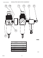
– 29 –
REGULATOR AND FILTER ASSEMBLY
Parts List P-184-E
8
10
1
2
3
4
IN
6
9
S18669-1
5-28-93B
Item
1
*
*
2
*
*
3
4
6
8
9
10
Description
Filter/Regulator Asbly
Filter Element (.50 ID x 1.14” Long)
Panel Mounting Nut
Oil/Coalescing Filter
Filter Element (.45 ID x 1.16” Long)
Filter Element (.56 ID x 1.42” Long)
Hex Nipple
Male Elbow
Hole Plug
Panel Mounting Nut
1/8 NPT Allen Head Plug
Pipe Plug
Part
No.
No.
Req’d.
M16480
M16480-B
M16480-C
S19865
S18637-2
S19865-A
T11289-1
S18451-2
T12250-1
M16480-C
M16480-D
S10780-4
1
1
1
1
1
1
1
1
1
1
1
1
7-2-91
9-6-93
– 30 –
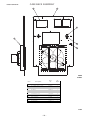
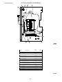
INPUT BOX ASSEMBLY
T2
W
REAR
VIEW
Parts List P-207-F
T1
V
U
4
T3
2
1
5
14
19
7
L1 L2 L3
CR2
FRONT
VIEW
17
21
20
L1 L2 L3
AC1 AC2 AC3
18
CR1
6
Part
No.
Item
Description
1
2
*
4
*
*
*
5
*
6
*
7
*
17
18
19
20
*
*
*
*
21
Input Box
Heat Sink
Thread Forming Screw
Reconnect Panel Asbly
Insulation
Plastic Expansion Nut
Self Tapping Screw
SCR PC Board Asbly, Includes:
SCR PC Board
Contactor
Self Tapping Screw
Contactor
Self Tapping Screw
Auxiliary Transformer
ID Sticker (CR1)
ID Sticker (CR2)
High Freq Module Asbly
High Freq Firing PC Board Asbly
Thread Forming Screw
Insulation
Capacitor
Capacitor Assembly
Self Tapping Screw
Plain Washer
Lockwasher
L8285
L8323
S9225-8
M16365-1
S18764-1
S14020-7
S8025-84
L8321
G2220-1
M12161-68
S8025-65
M12161-33
S8025-65
S13000-76
T14798-1
T14798-2
L8452-2
L8430-2
S9225-8
S20693
S13490-142
S18689-2
S8025-70
S9262-23
E106A-2
No.
Req’d.
L8322-1
6-12-96
1
1
4
1
1
4
4
1
1
1
3
1
3
1
1
1
1
1
2
1
1
1
3
2
2
6-12-96
– 31 –
HI FREQ BOARD ASSEMBLY
Parts List P-207-G
18
1
2
3
12
PILOT
WORK
14
17
20
6
10
L9320
6-12-96
Item
1
2
*
*
3
*
*
6
*
10
*
12
*
14
*
17
*
18
20
Description
Mounting Board Asbly
Carriage Bolt
Hex Nut
Brass Hex Nut
Sems Screw
Hex Nut (Brass)
Wing Nut
Carriage Bolt
Hex Nut
Coiler Asbly, Includes:
Hi-Freq Choke Coil
Mounting Bracket
Self Tapping Screw
Hi-Freq Transformer Asbly
Carriage Bolt
Resistor
Insulating Washer
Bushing
Bushing
Part
No.
S19700
T11827-23
1/4-20
1/4-20
T10082-8
#10-24
T9968-4
T11827-23
1/4-20
S19689
S19688
M15609
S8025-70
L9319
T11827-28
S10404-96
T4479-A
T14614-1
T14614-3
No.
Req’d.
1
1
2
1
1
1
1
2
4
1
1
1
2
1
2
1
2
1
1
6-12-96
– 32 –
CASE FRONT ASSEMBLY
1
2
Parts List P-184-D
3
6 7 8
9 12
5
4
13
L7713
5-28-93C
Item
1
2
2
3
*
4
5
6
7
8
9
9
12
13
Part
No.
Description
Case Front
Nameplate (Domestic)
Nameplate (Export)
PC Board Asbly
Self Tapping Screw
Reset Button (S2)
Run/Purge Switch (S2)
Potentiometer (R1)
Spacer
Knob
Line Switch Assembly (Dual & Triple Voltage)
Line Switch Assembly (Single Voltage)
Pan Head Screw
Hole Plug
– 33 –
G1873-1
L8315
L8354
M16301-1
S8025-71
T15089
T10800-13
T10812-40
S18280
T10491
M16284
M16284-1
T14731-16
T10397-20
No.
Req’d.
1
1
1
1
4
1
1
1
1
1
1
1
2
1
2-5-93
INPUT SUPPLY CONNECTION DIAGRAM
FOR SINGLE VOLTAGE MACHINE.
NOTE:
GND.
MACHINES ARE SHIPPED FROM FACTORY CONNECTED
LINK
FOR 575 VOLTS
575 V.,60HZ.
LINK POSITIONS
U
U
V
V
T3
9
6
11
5
12
8
10
W
1.
T1
W
4
T2
CONNECT U, V, & W INPUT SUPPLY LINES TO STUDS
7
MARKED U, V, & W ON RECONNECT PANEL.
2.
CONNECT TERMINAL MARKED
TO GROUND PER
NATIONAL ELECTRICAL CODE.
3.
REMOVE HEX NUTS AND POSITION LINKS AS SHOWN.
REPLACE AND TIGHTEN ALL HEX NUTS.
THE LINCOLN ELECTRIC CO.,
CLEVELAND, OHIO
U.S.A.
1-14-94B
M17491
FIGURE 1- SINGLE VOLTAGE
440 V.,50HZ.
460 V.,60HZ.
GND.
{
INPUT SUPPLY CONNECTION DIAGRAM
FOR TRIPLE VOLTAGE MACHINE.
NOTE: MACHINES ARE SHIPPED FROM FACTORY CONNECTED
LINK POSITIONS
U
U
V
V
W
W
T3
9
11
6
LINK
5
12
FOR 440 (OR 460) VOLTS
8
10
T1
4
T2
7
LINK POSITIONS
380 V.,50HZ.
{
GND.
LINK
T3
U
U
V
V
9
11
6
12
5
T1
8
W
10
W
4
T2
220 V.,50HZ.
230 V.,60HZ.
1. CONNECT U, V, & W INPUT SUPPLY LINES TO STUDS
2. CONNECT TERMINAL MARKED
NATIONAL ELECTRICAL CODE.
TO GROUND PER
GND.
{
MARKED U, V, & W ON RECONNECT PANEL.
LINK POSITIONS
U
V
V
W
W
9
6
5
THE LINCOLN ELECTRIC CO., CLEVELAND, OHIO U.S.A.
FIGURE 1- DUAL & TRIPLE VOLTAGE
T1
4
T2
5-28-93
12
10
8
– 34 –
LINK
T3
U
11
3. REMOVE HEX NUTS AND POSITION LINKS AS SHOWN.
REPLACE AND TIGHTEN ALL HEX NUTS.
7
7
M16437
Do not operate with covers removed
PLASMA TORCH CONNECTION DIAGRAM
Disconnect input power before servicing
FOR LINCOLN
Do not touch electrically live parts
Only qualified persons should install,
ELECTRIC TORCHES
use or service this equipment
ADAPTER
MOLEX CONNECTORS
GAS LINE
LOCK NUT
PILOT LEAD
CORD GRIP CONNECTOR
PILOT
WORK
WORK LEAD
1. DISCONNECT INPUT POWER TO THE PRO-CUT AND TURN
MACHINE POWER SWITCH OFF.
2. INSERT TORCH CABLE THROUGH CASE FRONT OPENING.
USE LOCK NUT TO MOUNT CORD GRIP CONNECTOR.
3. CONNECT PILOT LEAD.
4. PLACE GAS LINE FITTING ON ADAPTER AND SCREW TIGHT.
5. ATTACH MOLEX CONNECTORS.
THE LINCOLN ELECTRIC CO.
CLEVELAND, OHIO
U.S.A.
5-28-93
FIGURE 2
– 35 –
S19934
7
8
10
11
2
9
12
J23
7
4
24
VAC
8
11
PRESSURE
SWITCH
5
2
606
H3
6
575V CONNECTION
CONNECTION
220/380/440V
1
3
H2
13
14
15
110
VAC
24
VAC
230/460V
H1
H1
12
9
6
3
335
330 332
331 333
1 3
J3
31
31
CR1
32
FAN
32
J8
12 6 3 14 7 8 4
605
20
VAC
334
J7
2 4
10
9
7
8
6
5
4
216
215
214
211 213
212
1 2 3 7 5 6 4
J31
STATUS BOARD
380VAC
H2
J15
MAIN TRANSFORMER
INNER
PRI. 10
OUTER
PRI.
1
5J12
319
319
2
1
1
PRIMARY
COIL
THERMOSTAT
2
16
13
15
3
323
322
321
319
324
J8
JUMPER
OPTION
SWITCH
2J12
NEG
POS
405
REMOTE/LOCAL
324D
321D
STRIPS
TERMINAL
2B
4B
INTERFACE KIT
CNC & GMF
OPTIONAL
OPTIONAL
76C
2
3
1
6
1
3
8
5
10
2A
4A
403
404
76
75
401
402
400D
212D
J6
CONTROL BOARD
3 6
325
326
S3
383
G3
J14
SCR1
AC1
R
SCR3
AC2
-
SCR5
AC3
B
R
SCR6
1 8
2
75
1
4 10 5 11 6 12
SCR MODULE
P.C. BD.
9
R
SCR4
B
+
1 7 2 8 3
B
SCR2
J13
5 14 13 7 6
G6
G5
384 385 386
G4
9 10 2 3 11 12 4
382
G2
381
G1
5 6 4 3 9 10 11 12 1 2 7 8
9 5 10 11
218
8
TS1
SAFETY
RESET
221
BYPASS
BOARD
222
3
4D
POS
POS-D
2D
77D
L1
NEG
335
4
NEG
2
208
12K
10W
POS
71
337
336
5 7 6 8 3 4
J5
38
4
3
2
1
3
4
8
9
78
4
90W
D501
C501
78
32
71
388
HI FREQ
ASBLY.
+
70
72
394
15
100W
JUMPER
OPTION
J5
392
393
328
32
36
L2
607
607
605
4J12
L503
SV2
1
1 2
POS
32D
34
10
2
31
37
5
31D
6
11
13
7
12
390
CR2
CR2
391
389
L504
C1
608
389
3
300W
72
9
601
602
7
3 4
31
5
31
31
388
W
3
300W
306
E
6
5W
2
1 8
J16
PILOT
WORK
20
100W
S1
T3
T2
T1
TP2
TP1
5
2
6
3
4
1
J18
4
3
2
1
J17
TP3
220/230V
TO GROUND
PER NATIONAL
ELECTRICAL CODE
W
V
U
TO SUPPLY
LINES
ELECTRODE
604
603
20K
HI FREQ MODULE
606
N.B.
CR1
1J12
327
35
CR2
CR2
SV1
J12
JUMPER
14
OPTION
HALF OF
JUMPER J2
J10
JUMPER
OPTION
HARNESS
OPTION
OPTION
J11
J10
76B
76C
334
4 5
77
3 1 2 4
J4
J2
1
76
2
R1
10K
CW
OUTPUT
CONTROL
PRO-CUT 125
N.A.
8
10
4
9
6
7
12
TO PRIMARY
COILS
T2
5
11
T3
TO PRIMARY
COILS
T1
S1
T1
T2
T3
S1
T1
TP2
TP1
TP2
TP1
8
T2
5
T3
10
11
8
J16
1
5
9
7
4
2
6
3
(VIEWED FROM
N.B.
N.A.
NOTES
4
J8
7
12
T1
T1
J17
L10261
A
PN25098
NOT PRESENT ON SOME EARLY
MODELS.
7
12
J11, J25
NOZZLE (PILOT LEAD AT
THE TORCH).
6
J4, J7,
J18 PIN 3 CONNECTS TO THE
COMPONENT SIDE OF BOARD)
SEQUENCE.
9
6
J6, J14, J23
J3, J19
CONNECTOR CAVITY NUMBERING
J12, J18
J5, J31
J10, J13
J2, J15
4
TO PRIMARY
COILS
10
TO PRIMARY
COILS
T2
5
9
TO PRIMARY
COILS
8
T3
11
RESISTORS = OHM/WATT (1/2 WATT UNLESS
OTHERWISE SPECIFIED)
ELECTRICAL SYMBOLS PER E1537
TP3
TP3
OR 575V
440/460V
GENERAL INFORMATION
TO GROUND
PER NATIONAL
ELECTRICAL CODE
W
V
U
TO SUPPLY
LINES
380V
T3
T2
TO GROUND
PER NATIONAL
ELECTRICAL CODE
W
V
U
TO SUPPLY
LINES
NOTE: This diagram is for reference only. It may not be accurate for all machines covered by this manual. The specific diagram for a particular code is pasted inside
the machine on one of the enclosure panels. If the diagram is illegible, write to the Service Department for a replacement. Give the equipment code number..
JUMPER
J12 OPTION
HALF OF
PURGE/RUN
SWITCH
(PURGE IS
OPEN)
LOCAL
REMOTE
76D
76B
4
9
2
7
OPTIONAL
J25
J19
BOARD
OPTION
POS
405
NEG
2A
4A
75
76
401
402
324D
77D
76D
212D
1
4
3
5
6
R3
R8
POS-D
32D
31D
321D
400D
2D
4D
R6
+
R2
2B
4B
403
404
-
R5
R4
WIRING DIAGRAM
R7
– 36 –
Now Available...12th Edition
The Procedure Handbook of Arc Welding
New Lessons in Arc Welding
This printing will go fast so don’t delay. Place your
order now using the coupon below.
Lessons, simply written, cover manipulatory techniques;
machine and electrode characteristics; related subjects,
such as distortion; and supplemental information on arc
welding applications, speeds and costs. Practice materials,
exercises, questions and answers are suggested for each
lesson.
The hardbound book contains over 750 pages of welding
information, techniques and procedures. Much of this material
has never been included in any other book.
528 pages, well illustrated, 6” x 9” size, bound in simulated,
gold embossed leather.
$5.00 postage paid U.S.A. Mainland
With over 500,000 copies of previous editions published
since 1933, the Procedure Handbook is considered by many to
be the “Bible” of the arc welding industry.
A must for all welders, supervisors, engineers and
designers. Many welding instructors will want to use the book
as a reference for all students by taking advantage of the low
quantity discount prices which include shipping by
4th class parcel post.
$15.00 postage paid U.S.A. Mainland
Need Welding Training?
The Lincoln Electric Company operates the oldest and
most respected Arc Welding School in the United States at its
corporate headquarters in Cleveland, Ohio. Over 100,000 students have graduated. Tuition is low and the training is
“hands on”
How To Read Shop Drawings
The book contains the latest information and application
data on the American Welding Society Standard Welding
Symbols. Detailed discussion tells how engineers and
draftsmen use the “short-cut” language of symbols to pass
on assembly and welding information to shop personnel.
For details write:
Practical exercises and examples develop the reader’s ability
to visualize mechanically drawn objects as they will appear
in their assembled form.
Lincoln Welding School
22801 St. Clair Ave.
Cleveland, Ohio 44117-1199.
and ask for bulletin ED-80 or call 216-383-2259 and ask for the
Welding School Registrar.
187 pages with more than 100 illustrations. Size 8-1/2” x 11”
Durable, cloth-covered board binding.
$4.50 postage paid U.S.A. Mainland
Lincoln Welding School
BASIC COURSE
5 weeks of fundamentals
$700.00
There is a 10% discount on all orders of $50.00 or more for shipment at one time to one location.
Orders of $50 or less before discount or orders outside of North America must be prepaid with charge, check or money order in U.S. Funds Only.
Prices include shipment by 4 th Class Book Rate for U.S.A. Mainland Only. Please allow up to 4 weeks for delivery.
UPS Shipping for North America Only. All prepaid orders that request UPS shipment please add:
$5.00
For order value up to $49.99
$10.00
For order value between $50.00 & $99.99
$15.00
For order value between $100.00 & $149.00
For North America invoiced orders over $50.00 & credit card orders, if UPS is requested, it will be invoiced or charged to you at cost.
Outside U.S.A. Mainland order must be prepaid in U.S. Funds. Please add $2.00 per book for surface mail or $15.00 per book for air parcel post shipment.
METHOD OF PAYMENT: (Sorry, No C.O.D. Orders)
Name:
_______________________________________________
CHECK ONE:
❐
❐
❐
Address:
Please Invoice (only if order is over $50.00)
_______________________________________________
Check or Money Order Enclosed, U.S. Funds only
Credit Card - ❐
Account No.
VISA
®
❐
Telephone: _______________________________________________
MasterCard
®
|_|_|_|_|_|_|_|_|_|_|_|_|_|_|_|_|_|_|_|_|_|
USE THIS FORM TO ORDER:
BOOKS OR FREE INFORMATIVE CATALOGS
Lincoln Welding School
(ED-80)
❐
Seminar Information
(ED-45)
❐
Educational Video Information
(ED-93)
❐
James F. Lincoln Arc Welding
Foundation Book Information
(JFLF-515)
❐
_______________________________________________
Order from:
Exp Date
|_|_|
|_|_|
Month
Year
Signature as it appears on Charge Card:
______________________
BOOK DIVISION, The Lincoln Electric Company, 22801 St. Clair Avenue, Cleveland, Ohio 44117-1199
Telephone: 216-383-2211 or, for fastest service, FAX this completed form to: 216-361-5901.
Titles:
Price
New Lessons in Arc Welding
$5.00
Procedure Handbook “Twelfth Edition”
$15.00
How to Read Shop Drawings
$4.50
Incentive Management
$5.00
A New Approach to Industrial Economics $5.00
The American Century of John C. Lincoln $5.00
Welding Preheat Calculator
$3.00
Pipe Welding Charts
$4.50
Code
L
PH
H
IM
NA
AC
WC-8
ED-89
Quantity
SUB TOTAL
Additional Shipping Costs if any
TOTAL COST
– 37 –
Cost
● Do not touch electrically live parts or
WARNING
Spanish
AVISO DE
PRECAUCION
French
ATTENTION
German
WARNUNG
Portuguese
ATENÇÃO
● Keep flammable materials away.
● Wear eye, ear and body protection.
● Mantenga el material combustible
● Protéjase los ojos, los oídos y el
electrode with skin or wet clothing.
● Insulate yourself from work and
ground.
● No toque las partes o los electrodos
bajo carga con la piel o ropa mojada.
● Aislese del trabajo y de la tierra.
● Ne laissez ni la peau ni des vête-
fuera del área de trabajo.
● Gardez à l’écart de tout matériel
ments mouillés entrer en contact
avec des pièces sous tension.
● Isolez-vous du travail et de la terre.
● Berühren Sie keine stromführenden
inflammable.
● Entfernen Sie brennbarres Material!
Teile oder Elektroden mit Ihrem
Körper oder feuchter Kleidung!
● Isolieren Sie sich von den
Elektroden und dem Erdboden!
cuerpo.
● Protégez vos yeux, vos oreilles et
votre corps.
● Tragen Sie Augen-, Ohren- und Kör-
perschutz!
● Não toque partes elétricas e elec-
● Mantenha inflamáveis bem guarda-
trodos com a pele ou roupa molhada.
● Isole-se da peça e terra.
dos.
● Use proteção para a vista, ouvido e
corpo.
Japanese
Chinese
Korean
Arabic
READ AND UNDERSTAND THE MANUFACTURER’S INSTRUCTION FOR THIS EQUIPMENT AND THE CONSUMABLES TO BE
USED AND FOLLOW YOUR EMPLOYER’S SAFETY PRACTICES.
SE RECOMIENDA LEER Y ENTENDER LAS INSTRUCCIONES DEL FABRICANTE PARA EL USO DE ESTE EQUIPO Y LOS
CONSUMIBLES QUE VA A UTILIZAR, SIGA LAS MEDIDAS DE SEGURIDAD DE SU SUPERVISOR.
LISEZ ET COMPRENEZ LES INSTRUCTIONS DU FABRICANT EN CE QUI REGARDE CET EQUIPMENT ET LES PRODUITS A
ETRE EMPLOYES ET SUIVEZ LES PROCEDURES DE SECURITE DE VOTRE EMPLOYEUR.
LESEN SIE UND BEFOLGEN SIE DIE BETRIEBSANLEITUNG DER ANLAGE UND DEN ELEKTRODENEINSATZ DES HERSTELLERS. DIE UNFALLVERHÜTUNGSVORSCHRIFTEN DES ARBEITGEBERS SIND EBENFALLS ZU BEACHTEN.
– 38 –
● Keep your head out of fumes.
● Use ventilation or exhaust to
● Turn power off before servicing.
● Do not operate with panel open or
guards off.
remove fumes from breathing zone.
● Los humos fuera de la zona de res-
piración.
● Mantenga la cabeza fuera de los
humos. Utilice ventilación o
aspiración para gases.
● Gardez la tête à l’écart des fumées.
● Utilisez un ventilateur ou un aspira-
● Desconectar el cable de ali-
● No operar con panel abierto o
mentación de poder de la máquina
antes de iniciar cualquier servicio.
● Débranchez le courant avant l’entre-
tien.
Schweibrauch!
● Sorgen Sie für gute Be- und
Entlüftung des Arbeitsplatzes!
● Mantenha seu rosto da fumaça.
● Use ventilação e exhaustão para
remover fumo da zona respiratória.
● N’opérez pas avec les panneaux
ouverts ou avec les dispositifs de
protection enlevés.
teur pour ôter les fumées des zones
de travail.
● Vermeiden Sie das Einatmen von
guardas quitadas.
● Strom vor Wartungsarbeiten
● Anlage nie ohne Schutzgehäuse
abschalten! (Netzstrom völlig öffnen; Maschine anhalten!)
oder Innenschutzverkleidung in
Betrieb setzen!
● Não opere com as tampas removidas.
● Desligue a corrente antes de fazer
● Mantenha-se afastado das partes
serviço.
● Não toque as partes elétricas nuas.
● Não opere com os paineis abertos
moventes.
WARNING
Spanish
AVISO DE
PRECAUCION
French
ATTENTION
German
WARNUNG
Portuguese
ATENÇÃO
ou guardas removidas.
Japanese
Chinese
Korean
Arabic
LEIA E COMPREENDA AS INSTRUÇÕES DO FABRICANTE PARA ESTE EQUIPAMENTO E AS PARTES DE USO, E SIGA AS
PRÁTICAS DE SEGURANÇA DO EMPREGADOR.
– 39 –
• World's Leader in Welding and Cutting Products •
• Sales and Service through Subsidiaries and Distributors Worldwide •
Cleveland, Ohio 44117-1199 U.S.A. TEL: 216.481.8100 FAX: 216.486.1751 WEB SITE: www.lincolnelectric.com