1
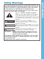
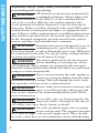
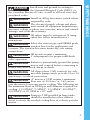
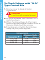
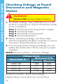
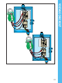
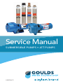
Service Manual
SUBMERSIBLE PUMPS • JET PUMPS
GSSERVICE
TABLE OF CONTENTS
Submersibles: (Pages 1 – 61)
Page
Safety Warnings.............................................................. 1-3
Typical Systems............................................................... 4-5
Motor Cooling.................................................................... 6
Troubleshooting.............................................................. 7-9
Amprobe Instructions...................................................... 10
Ohmmeter Instructions................................................... 11
Measuring Insulation Resistance.................................... 12
Coil Checkout................................................................... 13
Relay Checkout...........................................................14-15
Contactor Checkout........................................................ 16
Overload Checkout......................................................... 17
Capacitor Checkout......................................................... 18
Fuse Checkout.................................................................. 19
Voltage Checkout.......................................................20-23
Amperage Checkout..................................................24-25
Wire Diagrams............................................................26-31
Cable Checkout..........................................................32-33
Motor Insulation & Winding Resistance...................34-37
1Ø Motor Data and Wire Sizing................................38-43
3Ø Motor Data and Wire Sizing................................44-49
Aquavar SOLO Wire Sizing........................................50-51
3Ø 6" – 10" Motor Data..............................................52-55
Pressure Tank Checkout.............................................56-57
Jet Pumps: (Pages 58 – 92)
Typical Systems...........................................................58-59
Jet Pumps....................................................................60-63
Troubleshooting..........................................................64-69
Voltage Check.................................................................. 70
Amperage Checks......................................................71-72
Ohmmeter Checks.....................................................73-79
Pressure Switch Adjustment Checkout......................... 80
Checking Suction Lift..................................................81-82
Pressure Control Valves................................................... 83
Rotation............................................................................. 84
Three Phase Unbalance.............................................85-86
Transformer Sizes........................................................87-88
Quick Start Guides......................................................89-92
TO AVOID SERIOUS OR FATAL PERSONAL INJURY OR
MAJOR PROPERTY DAMAGE, READ AND FOLLOW ALL
SAFETY INSTRUCTIONS IN MANUAL AND ON PUMP.
THIS MANUAL IS INTENDED TO ASSIST IN THE INSTALLATION AND OPERATION OF THIS UNIT AND
MUST BE KEPT WITH THE PUMP.
This is a SAFETY ALERT SYMBOL.
When you see this symbol on the pump
or in the manual, look for one of the following signal words and be alert to the
potential for personal injury or property
damage.
of hazards that WILL cause
DANGER Warns
serious personal injury, death or major
property damage.
WARNING Warns of hazards that CAN cause serious
personal injury, death or major property
damage.
Warns of hazards that CAN cause perCAUTION sonal injury or property damage.
NOTICE: INDICATES SPECIAL INSTRUCTIONS WHICH ARE VERY IMPORTANT AND MUST BE FOLLOWED.
THOROUGHLY REVIEW ALL INSTRUCTIONS AND
WARNINGS PRIOR TO PERFORMING ANY WORK
ON THIS PUMP.
MAINTAIN ALL SAFETY DECALS.
1
SAFETY WARNINGS
Safety Warnings
SAFETY WARNINGS
Important notice: Read safety instructions before
proceeding with any wiring.
WARNING All electrical work must be performed by
a qualified technician. Always follow the
National Electrical Code (NEC), or the Canadian Electrical Code, as well as all local, state and provincial codes.
Code questions should be directed to your local electrical
inspector. Failure to follow electrical codes and OSHA safety
standards may result in personal injury or equipment damage. Failure to follow manufacturer’s installation instructions
may result in electrical shock, fire hazard, personal injury or
death, damaged equipment, provide unsatisfactory performance, and may void manufacturer’s warranty.
WARNING Standard units are not designed for use in
swimming pools, open bodies of water,
hazardous liquids, or where flammable gases exist. Well must
be vented per local codes. See specific pump catalog bulletins
or pump nameplate for all agency Listings.
WARNING Disconnect and lockout electrical power
before installing or servicing any electrical equipment. Many pumps are equipped with automatic
thermal overload protection which may allow an overheated
pump to restart unexpectedly.
WARNING Never over pressurize the tank, piping or
system to a pressure higher than the tank's
maximum pressure rating. This will damage the tank, voids
the warranty and may create a serious hazard.
WARNING Protect tanks from excessive moisture and
spray as it will cause the tank to rust and
may create a hazard. See tank warning labels and IOM for
more information.
WARNING Do not lift, carry or hang pump by the
electrical cables. Damage to the electrical cables can cause shock, burns or death.
WARNING Use only stranded copper wire to pump/
motor and ground. The ground wire must
be at least as large as the power supply wires. Wires should
be color coded for ease of maintenance and troubleshooting.
2
3
SAFETY WARNINGS
Install wire and ground according to
the National Electrical Code (NEC), or
the Canadian Electrical Code, as well as all local, state and
provincial codes.
WARNING Install an all leg disconnect switch where
required by code.
WARNING The electrical supply voltage and phase
must match all equipment requirements.
Incorrect voltage or phase can cause fire, motor and control
damage, and voids the warranty.
WARNING All splices must be waterproof. If using
splice kits follow manufacturer’s instructions.
WARNING Select the correct type and NEMA grade
junction box for the application and location. The junction box must insure dry, safe wiring connections.
WARNING All motors require a minimum 5' submergence for proper refill check
valve operation.
WARNING Failure to permanently ground the pump,
motor and controls before connecting to
power can cause shock, burns or death.
WARNING All three phase (3Ø) controls for submersible pumps must provide Class 10,
quick-trip, overload protection.
WARNING 4" motors ≥ 2 HP require a minimum
flow rate of .25 ft/sec. or 7.62 cm/sec.
past the motor for proper motor cooling. The following are
the minimum flows in GPM per well diameter required for
cooling: 1.2 GPM/4", 7 GPM/5", 13 GPM/6", 20 GPM/7",
30 GPM/8" or 50 GPM in a 10" well.
WARNING Pumps ≥ 2 HP installed in large tanks
should be installed in a flow inducer
sleeve to create the needed cooling flow or velocity past the
motor.
DANGER
TYPICAL SYSTEM
Two-Wire System Illustrated
RULE OF THUMB
1.
2.
Use same size or larger pipe as discharge on pump.
Always use a check valve for every 200 ft. of vertical pipe.
To House Piping
Protected Power Supply
Disconnect
Switch
Shut-off
Valve
Union
Pressure
Switch
Pressure
Relief Valve
Drain
Tap
Pitless
Adapter ➀
Check
Valve ➀
Tank Tee
Frost Level
Check Valve ➁
➀ On installations with a pitless adapter
the top check valve should be below
the pitless, not at the tank, as the
discharge line should be pressurized
back to the pitless.
➁ On installations with well seals or well
pits it is allowable to locate the top
check valve near the tank.
CAUTION
All electrical equipment must be connected
to supply ground. Follow applicable code
requirements.
4
TYPICAL SYSTEM
Motor Cooling, Temperature
and Time Ratings
All 4 inch CentriPro motors may be
operated continuously in water up to 86º
F. Optimum service life will be attained
by maintaining a minimum flow rate past
the motor of .25 feet per second. Use a
Flow Sleeve if velocity is below the .25'/
sec, if the well is top feeding or when the
pump is used in a large body of water or
large tank.
Six (6) inch canned design motors from
5 – 40 HP will operate in water up to
95º F (35º C), without any de-rating of
horsepower, with a minimum flow rate of
.5 ft./sec. past the motor. 6" – 50 HP and
all 8" – 10" motors can operate in 77º F
(25º C) water with .5'/sec velocity past
FLOW SLEEVE
the motor.
One way to make a flow sleeve is to install a well seal
above the pump discharge and slip a piece of casing
over the pump and affix it to the well seal. Drill three
holes at 120º intervals on the lower section of the casing
and insert (3) screws and nuts through the casing, just
touching the motor. Tighten the nuts out against the
casing. Insure that the screws do not protrude out too
far as you don’t want them catching on well joints.
Pump Cooling and Lubrication
In addition to motor cooling, another reason to
maintain minimum flow rates is pump lubrication. All
manufacturers’, either on curves or in selection charts,
show minimum flows. This insures that rotating pump
parts are properly lubricated to prolong service life and
reduce friction. A dead headed pump will super heat
water very quickly, and hot water has no lubricity.
5
TECHNICAL DATA
Minimum Flow Rates for
Proper Motor Cooling
3.75" Dia. CP = FE = CP =
Well or 4" CP or 5.5" Dia. 5.38" Dia.7.52" Dia.
Sleeve FE Motor 6" CP
6" FE
8" CP
Diameter
.25'/secMotorMotorMotor
(inches) .5'/sec. .5'/sec. .5'/sec.
GPM Required
41.2
–––
57–––
6
13
7
9
–
7 202325 –
8 304145 9
10 50859053
12 80 139140107
14 110198200170
16 150276280313
Multiply gpm by .2271 for m3/Hr.
Multiply gpm by 3.785 for l/min.
IMPORTANT
This manual is intended ONLY for use by
professionals familiar with NEC (National
Electric Codes) electrical codes and
hydraulic and safety procedures of pump
installations.
6
Probable Cause
1. Motor thermal protector
tripped
a. Incorrect control box
b. Incorrect or faulty electrical connections
c. Faulty thermal protector
d. Low voltage
e. Ambient temperature of control box/starter too high
f. Pump bound by foreign matter
g. Inadequate submergence
Recommended Action
1. Allow motor to cool, thermal protector will automatically reset
2. Open circuit breaker or
blown fuse
2. Have a qualified electrician inspect and repair, as
required
3. Power source inadequate
for load
4. Power cable insulation
damage
5. Faulty power cable splice
3. Check supply or generator
capacity
4 – 5. Have a qualified electrician inspect and repair, as
required
a – e. Have a qualified electrician inspect and repair,
as required
f. Pull pump, clean, adjust set
depth as required
g. Confirm adequate unit
submergence in pumpage
RULE OF THUMB
Remember, there may be other
system problems caused by
auxiliary controls not covered in
this booklet.
7
TROUBLESHOOTING
Pump Motor Not Running
TROUBLESHOOTING
Little or No Liquid Delivered by Pump
Probable Cause
1. Faulty or incorrectly installed
check valve
Recommended Action
1. Inspect check valve, repair
as required
2. Pump air bound
2. Successively start and
stop pump until flow is
delivered
3. Review unit performance,
check with dealer
3. Lift too high for pump
4. Pump bound by foreign
matter
4. Pull pump, clean, adjust set
depth as required
5. Pump not fully submerged
5. Check well recovery, lower
pump if possible
6. Well contains excessive
amounts of air or gases
6. If successive starts and
stops does not remedy,
well contains excessive air
or gases
7. Excessive pump wear
7. Pull pump and repair as
required
8. Incorrect motor rotation
– 3Ø only.
8. Reverse any two motor
electrical leads
8
Probable Cause
1. No power
Recommended Action
1. Check for tripped circuit
breaker
2. Incorrect voltage
2. Check with voltmeter
3. Defective pressure switch
3. Inspect switch points and
wires
4. Loose wire connections
4. Check all connections and
splices
5. Cable insulation damaged
5. Perform cable check with
ohmmeter
6. Damaged or poor splice
6. Perform cable check with
ohmmeter
7. Pump bound by sand or
abrasives
7. Pull pump and repair as
required
Pump Starts Too Frequently. . .
Probable Cause
1. Waterlogged tank
Recommended Action
1. Check tank pressure when
empty of water
2. Check valve broken or stuck
open
2. Replace check valve
3. Improper switch setting
3. Adjust switch
4. Improper switch placement
4. Move switch closer to tank
5. Leaks in piping
5. Replace defective pipe
6. Tank too small for pump
6. Install larger tank
9
TROUBLESHOOTING
Pump Will Not Start or Run. . .
AMPROBE/OHMMETER INSTRUCTIONS
The Amprobe is a multi-range, combination
ammeter and voltmeter.
Voltmeter Scales: 150 Volts
600 Volts
Ammeter Scales:
5 Amps
40 Amps
15 Amps
100 Amps
1.When used as an ammeter, the tongs are placed around the wire being measured with the rotary scale on the 100 amp range. Then rotate the scale back to the smaller ranges until an exact reading is indicated.
2. When used as a voltmeter, the two leads are clipped into the bottom of the instrument with the rotary scale on the 600 volt range. If the reading is less than 150 volts, rotate the scale to the 150 volt range to get a more exact reading.
10
CAUTION
Use Ohmmeter only with power off.
11
AMPROBE/OHMMETER INSTRUCTIONS
The Ohmmeter is used for measuring the
electrical resistance of a wire circuit. The unit of
measurement is called an Ohm.
1.The knob at the bottom of the Ohmmeter is adjustable through six ranges:
RX1
= R x 1
If your ohmmeter
RX10
= R x 10
is digital readout
RX100
= R x 100
type, refer to the
RX1000 = R x 1,000
instructions that
RX10K = R x 10,000
came with it.
RX100K = R x 100,000
2. The round center knob is for the purpose of adjusting the instrument to zero (0) after clipping the two ohmmeter leads together. This must be done every time the range selection is changed.
MEASURING INSULATION RESISTANCE
Megger
This instrument is used to measure insulation
resistance to ground. It consists of a crankturned magneto, on the side of the case, and
will give very close readings calibrated directly in ohms. It is cranked at a moderate rate
of speed, approximately 120 rpm, until the
pointer reaches a steady deflection.
1. If the ohm value is normal, the motor
windings are not grounded and the cable
insulation is not damaged.
2. If the ohm value is below normal, either the
windings are grounded or the cable insulation is damaged. Check the cable at the well
seal as the insulation is sometimes damaged
by being pinched.
12
COIL CHECKOUT
!
WARNING!
Open master breaker and disconnect all
leads from starter to avoid damage to
meter or electric shock hazard. Connect
the ohmmeter leads as shown above.
Coil with Ohmmeter
1.Set R x 1000.
2.Connect leads as shown.
3.Reading: Should register some value,
Approx. 200-1000 ohms.
What It Means –
Infinity reading indicates coil is open. Zero reading indicates coil is shorted. In either case,
the coil should be replaced.
A reading of 200-1000 ohms indicates coil is
ok.
13
RELAY CHECKOUT
Voltage Relay
CONTROL BOXES (CENTRIPRO OR F.E.)
Checking Relay with Ohmmeter
A. Voltage Relay Tests
Step 1, Coil Test
1. Meter setting: R x 1,000.
2. Connections: #2 & #5.
3. Correct meter readings:
For 115 Volt Boxes:
.7 – 1.8 (700 to 1,800 ohms).
For 230 Volt Boxes
4.5 – 7.0 (4,500 to 7,000 ohms).
14
RELAY CHECKOUT
Voltage Relay
CONTROL BOXES (CENTRIPRO OR F.E.)
Step 2, Contact Test
1. Meter setting: R x 1.
2. Connections: #1 & #2.
3. Correct meter reading:
Zero for all models.
B. F.E. Blue Relay - Solid State
1
⁄3 – 1 HP QD Control Boxes Used from 1994 until present time:
Step 1, Triac Test
1. Meter setting: R x 1,000.
2. Connections: Cap and B terminal.
3. Correct meter reading: Infinity for all
models.
Step 2, Coil Test
1. Meter setting: R x 1.
2. Connections: L1 and B.
3. Correct meter reading:
Zero ohms for all models.
15
CONTACTOR CHECKOUT
Checkout Procedure
for Magnetic and Other
Contactors
Contactor Coil Test
(Disconnect lead from one side of coil)
1. Meter setting: R X 100
2. Connections: Coil terminals
3. Correct meter reading: 180 to
1,400 ohms
Contactor Contact Test
1. Meter Setting: R X 1
2. Connections: L1 & T1 or L2 & T2
3. Manually close contacts
4. Correct meter reading: Zero ohms
Additional information on troubleshooting and replacement parts for 1Ø Control Boxes
is available in the MAID; Motor Application
and Installation Manual. It is also available
online at www.xyleminc.com/brands/
gouldswatertechnology.
16
1. Set Ohmmeter at “R x 1”
2. Connect the Ohmmeter leads to Terminal
#1 and #3 on each Overload Protector.
3. Reading should be not more than 0.5
Ohms maximum on the scale.
CSCR or Mag. Contactor Control Box
17
OVERLOAD CHECKOUT
For 1½ HP (and Larger)
Control Box
CAPACITOR CHECKOUT
Capacitor with Ohmmeter
CAUTION
Discharge the capacitor before making
this check. (A screwdriver can be used
to make contact between capacitor’s
posts.)
1.Disconnect leads to capacitor post.
2.Setting: R x 1,000
3.Connect ohmmeter leads to capacitor posts.
4.Reading: Pointer should swing toward zero, then back toward infinity.
18
FUSE CHECKOUT
1. Set R x 1.
2. Connect leads as shown.
3. Reading: Should register zero.
What It Means –
Zero reading indicates fuse OK. Infinity (∞)
reading indicates bad fuse.
19
VOLTAGE CHECKOUT
To Check Voltage with “Q.D.”
Type Control Box
1. Remove cover to break all motor
connections.
CAUTION
L1 and L2 are still connected to power.
2. To check VOLTAGE: Use voltmeter on L1
and L2 as shown.
3. When checking voltage, all other major
electrical appliances (that could be in use at
the same time) should be running.
4. If readings are not within the limits (see
chart), call your power supplier.
Voltage Limits
Measured Volts
Nameplate ▼ Min.Max.
115V 1Ø
105
125
208V 1Ø
188
228
230V 1Ø
210
250
20
VOLTAGE CHECKOUT
21
VOLTAGE CHECKOUT 3Ø STARTER
Checking Voltage at Fused
Disconnect and Magnetic
Starter
!
WARNING!
Power is ON during voltage checking.
1.To check voltage: Use voltmeter on L1, L2
and L3 in sequence. Check should be made
at four locations.
Step 1 Checking incoming power supply.
Step 2 Checking fuses.
Step 3 Checking contact points
Step 4 Checking heaters.
2.When checking voltage, all other major
electrical appliances (that could be in use at
the same time) should be running.
3.If incoming power supply readings are not
within the limits (see chart), call your power
supplier.
NOTE:Phase to phase – full line voltage.
Voltage Limits
Measured Volts
Name Plate ▼
MinimumMaximum
208V 3Ø
188
228
230V 3Ø
207
253
460V 3Ø
414
506
575V 3Ø
518
632
Phase to neutral – ½ full line voltage.
(depending on transformer connection)
22
VOLTAGE CHECKOUT
VOLT
600 500 400 300 200 100 0-
VOLT
600 500 400 300 200 100 0-
23
CURRENT (AMPERAGE) CHECKOUT
!
WARNING!
Power is ON during current checking.
Using Amprobe
1.Set scale to highest amp range.
2.Connect amprobe around lead as shown.
3.Rotate scale to proper range and read
value.
4.Compare value with table.
What It Means –
Currents above these values indicate system
problems.
24
data.
Service Factor Amps with Magnetic Contactor
Control Boxes
6"
Franklin Electric
CentriPro 3-Wire
1Ø
3-Wire
HPVoltsYelBlackRed Yel Black
Red
5 27.5N/A N/A27.517.410.5
7.5
41.0N/A N/A42.140.55.4
230
10 58.0N/A N/A51.047.58.9
15 85.0N/A N/A75.062.516.9
25
CURRENT (AMPERAGE) CHECKOUT
Service Factor Amps with QD (½ - 1 HP) or CSCR (1.5 HP & Larger) Control Boxes ①
4"
CP
F.E.
CP F.E.
1Ø
3-Wire
3-Wire
2-Wire2-Wire
HPVoltsYelBlackRedYel BlackRedBlack Black
½ 115 12.6 12.6 0 12.0 12.0 0 9.5 12.0
½ 6.3 6.3 0 6.0 6.0 0 4.7
6.0
¾ 8.3 8.3 0 8.0 8.0 0 6.4
8.0
1 9.7 9.7 0 9.8 9.8 0 9.1 9.8
1½ 230 11.1 11.0 1.3 11.5 11.0 1.3 11.0 13.1
2 12.2 11.7 2.613.2 11.9 2.6
3 16.5 13.9 5.617.0 12.6 6.0
N/A
5 27.022.010.0
27.5 19.110.8
① Generation I CentriPro data. See pages 37-41 for Generation II
To Fused Disconnect
Or Circuit Breaker 3Ø
3 L1 L2 L3
1
L2
Magnetic
Starter
3 Phase Starter
T1 T2 T3
To Pump Motor
Ground
Line
Load
Line
Load
TYPICAL WIRING DIAGRAMS
Magnetic Starter and Pressure
Switch
Pressure Switch
Requires class 10
quick trip “k-heaters”
(overloads), or adjustable class 10
overloads such as ESP100, ESP 200
NOTE:
Check to be sure proper selection of
pressure switch matched to system
voltage has been made... refer to
catalog data.
Check that starter has ground.
26
TYPICAL WIRING DIAGRAMS
To Fused Disconnect
Or Circuit Breaker
3Ø
Magnetic
Starter
Line
Load
To Pump Motor
Ground
Pressure
Switch
RULE OF THUMB
Check that starter has ground.
27
To Fused Disconnect
Or Circuit Breaker 3Ø
Magnetic
Starter
3 L1 L2 L3
1
L2
3 Phase Starter
T1 T2 T3
Input Power
(As Required
By Level Control)
To Pump Motor
1
Line
Load
Line
Load
TYPICAL WIRING DIAGRAMS
Magnetic Starter, Pressure
Switch and Liquid Level
Control
3
6
9
7
2
Ground
Level
Control
5
Pressure Switch
Lower Upper
Ground
Electrode
NOTE:
Check to be sure proper selection of
pressure switch matched to system voltage
has been made... refer to catalog data.
Check that starter has ground.
28
TYPICAL WIRING DIAGRAMS
To Fused Disconnect
Or Circuit Breaker
3Ø
Input Power (As Required
By Level Control)
Ground
Magnetic
Starter
To Pump Motor
Lower Upper
Electrode
Line
Load
Ground
Pressure
Switch
29
TYPICAL WIRING DIAGRAMS
2-Wire Pump Wiring Diagram
with PumpSaver Plus 233P
30
31
TYPICAL WIRING DIAGRAMS
Standard 3-Wire Control Box
Wiring Diagram with
PumpSaver Plus 233P
CABLE CHECKOUT
Checking Cable and Splice
1. Submerge cable and splice in steel barrel
of water with both ends out of water.
2. Set ohmmeter selector on RX100K and
adjust needle to zero (0) by clipping
ohmmeter leads together.
3. After adjusting ohmmeter, clip one
ohmmeter lead to barrel and the other to
each cable lead individually, as shown.
4. If the needle deflects to zero (0) on any
of the cable leads, pull the splice up out
of the water. If the needle falls back to (∞)
(no reading) the leak is in the splice.
5. If leak is not in the splice, pull the cable
out of the water slowly until needle falls
back to (∞) (no reading). When the needle
falls back, the leak is at that point.
6. If the cable or splice is bad, it should be
repaired or replaced.
32
CABLE CHECKOUT
Checking Cable and Splice Test
O H M S
Ohmmeter
Set at RX 100K
RX100
RX10
RX1
ZERO
OHMS
RX1000
RX10K
RX 100K
Attach this Lead
to Metal Tank
33
MOTOR INSULATION RESISTANCE
1.Set the scale lever to R x 100K and adjust to 0.
CAUTION
Open (turn off) master breaker and
disconnect all leads from control box or
pressure switch (Q-D type control, remove lid) to avoid damage to meter or electric
shock hazard.
2.Connect an ohmmeter lead to any one of the motor leads and the other to the metal drop pipe. If the drop pipe is plastic, connect the ohmmeter lead to the metal well casing or ground wire.
OHMS
R x 100K
Drop
Cable
with
Ground
Wire
34
R x 100
R x 10
Rx1
ZERO
OHMS
R x 1000
R x 10K
R x 100K
Insulation resistance does not vary with rating. All
motors of all HP, voltage and phase rating have similar
values of insulation resistance.
Condition of Motor and Leads
A new motor (without drop cable).
A used motor which can be reinstalled in the well.
Ohms Megohm
ValueValue
20,000,000
20.0
(or more)
10,000,000
10.0
(or more)
New motor in the well
Motor in the well in good condition Insulation damage, locate and repair
2,000,000
2.0
(or more) (or more)
500,000 – 2,000,000 0.5 – 2.0
Less than Less than
500,000.50
What it Means
1. If the ohm value is normal, the motor windings
are not grounded and the cable insulation is not
damaged.
2. If the ohm value is below normal, either the
windings are grounded or the cable insulation
is damaged. Check the cable at the well seal as
the insulation is sometimes damaged by being
pinched.
35
MOTOR INSULATION RESISTANCE
Normal Ohm and Megohm Values (Insulation Resistance) Between All Leads and Ground
MOTOR WINDING RESISTANCE CHECKOUT
1. Set the scale lever to R x 1 for values under 10 ohms.
For values over 10 ohms, set the scale lever to R x 10.
Zero balance the ohmmeter as described earlier.
!
WARNING!
Open master breaker and disconnect all
leads from starter to avoid damage to meter
or electric shock hazard. Connect the ohmmeter leads as shown below.
2. Connect the ohmmeter leads as shown below.
Cable Resistance – Copper
Paired Wire
Size
CableResistance
(ohms per foot)
14
.0050
12
.0032
10
.0020
8 .0013
6 .0008
RX100K
4
.0005
2 .0003
Drop 0
.0002
Cable
With 00
.00015
Ground
Wire 000
.00013
0000
.00010
O H MS
RX100
RX10
RX1
ZERO
OHMS
If aluminum cable is used the
readings will be higher. Divide
the ohm readings on this chart
by 0.61 to determine the actual
resistance of aluminum cable.
Ground
Wire
OHMS
RX1000
RX10K
RX100K
RX100
RX10
RX1
Motor
Leads
ZERO
OHMS
RX1000
RX10K
RX100K
RX1
or
RX10
See motor data pages for motor resistance ratings.
What it Means
1. If all ohm values are normal, the motor windings are
neither shorted nor open, and the cable colors are
correct.
2. If any one ohm value is less than normal, the motor is
shorted.
3. If any one ohm value is greater than normal, the winding
or the cable is open or there is a poor cable joint or
connection.
4. If some ohm values are greater than normal and some
less, the leads are mixed.
36
3-Wire CentriPro Motors Winding Resistance ¹
Generation I
Generation II
HP
Volts Winding Resistance Winding Resistance
Main (B-Y) Start (R-Y) Main (B-Y) Start (R-Y)
0.5 115 .9-1.6
5.7-7 1.0-1.4 2.5-3.1
0.5 230 4.2-4.917.4-18.75.1-6.112.4-13.7
0.752302.6-3.611.8-132.6-3.310.4-11.7
1.0 230 2.2-3.211.3-12.32.0-2.6 9.3-10.4
1.52301.6-2.37.9-8.72.0-2.69.3-10.4
2 2301.6-2.210.8-121.6-2.210.8-12.0
32301.1-1.42-2.51.1-1.42.0-2.5
5 230 .62-.761.36-1.66.62-.761.36-1.66
¹ Generation II 3-wire were introduced in February 2012.
4" Franklin Electric Winding Resistance
Winding KVA
Type HPVolts
ResistanceCode
½ 115 1.0-1.3
R
½ 230 4.2-5.2
R
2-Wire
¾
230
3.0-3.6
N
1 230 2.2-2.7
N
1½ 230 1.5-1.9
M
Type
HP Volts 3-Wire
½
115
½
w/Q.D.
Cap.
¾
Start
1
3-Wire
1½230
w/CSCR
2
(CR)
3
Control
5
Box
Resistance
KVA
Main
Start
Code
(B-Y)
(R-Y)
1.0-1.3
4.1-5.1
M
4.2-5.2 16.7-20.5 M
3.0-3.6 10.7-13.1 M
2.2-2.7 9.9-12.1 L
1.7-2.2
8.0-9.7
J
1.8-2.3 5.8-7.2 G
1.0-1.5 3.5-4.4 H
.68-1.0 1.8-2.2 F
RULE OF THUMB
Add resistance of drop cable when checking
pump in well. See Cable Resistance.
37
MOTOR WINDING RESISTANCE CHECKOUT
Motor Resistance
MOTOR DATA
2-Wire PSC, 1Ø, 4" Motors – Electrical Data, 60 Hz, 3450 RPM
GENERATION I – 2-Wire CentriPro Motors Resistance,
Amps and KVA Code ²
HP Volts FLA SF Amps LRA
0.51157.4 9.5
36
0.52303.7 4.7
20
0.75 230 5
6.4
25
1.02307.9 9.1
22
1.52309.2 11
42
Ohms
KVA
1.3-1.8 K
4.5-5.2 K
3-4.8
J
4.2-5.2 F
1.9-2.3 H
GENERATION II – 2-Wire CentriPro Motors Resistance,
Amps and KVA Code ²
HP Volts FLA SF Amps LRA
0.51157.9 9.8
28
0.5 230 4
4.7
16
0.75 230 5
6.2
18
1.02306.7 8.1
24
1.5 230 9
10.4
44
Ohms
KVA
1.4-2 H
6.1-7.2
J
5.9-6.9
F
4.2-5.2 F
1.8-2.4
H
² Generation I sold up to December 2011, Generation II introduced in
December 2011.
NOTE: Generation II motors have a -01 suffix on motor nameplate Model
No. ex. Gen I = M05412, Gen II = M05412-01.
38
Fuse or Circuit Breaker Amps
Type Order No. HP Standard Dual Element Circuit
CentriPro
Fuse
Time Delay Breaker
M054210.5 25
15
20
M05422 0.5
15
10
10
2-Wire
M074220.75 20
10
15
(PSC)
M104221.0 25
15
20
M154221.5 30
15
25
M05411 0.5
30
20
30
3-Wire
M054120.5 15
10
15
QD
M07412 0.75 20
10
20
(CSIR)
M104121.0 25
15
25
M054120.5 15
10
10
M074120.75 20
10
15
M10412 1.0
20
10
15
3-Wire
M15412 1.5 30
15
25
CSCR
M204122.0 30
20
25
M304123.0 45
25
40
M504125.0 70
40
60
Motor Resistance
1Ø Motors – Winding Resistance Motor Only (Ohms)
6" Motors
CentriProFranklin Electric
Resistance KVA
Resistance
KVA
Type HPVolts
R - Y B - Y R - B Code (B-Y)
(R-Y) Code
5 2.17 0.512.63 G .55-.68 1.3-1.7 E
1.40 0.4 1.77 F .36-.50 .88-1.1 F
6" 7.5
230
1Ø 10 1.05 0.3161.31 E .27-.33 .80-.99 E
15 0.68 0.230.85 D .17-.22 .68-.93 E
39
MOTOR DATA
2-Wire and 3-Wire – Fuse and
Circuit Breaker Amps
MOTOR DATA
3-Wire, 1Ø, 4" Motors Electrical Data, 60 Hz, 3450 RPM
Order No.
HP
Volts
SF
Type CentriPro
3-Wire
with Q.D.
Cap.
Start
Box
M05411
0.5
115
1.6
M05412
0.5
1.6
M07412
0.75
1.5
M10412
1.0
1.4
M05412
0.5
1.6
M07412
0.75
230
1.5
3-Wire
with
CSCR
M10412
1.0
1.4
(CR)
or
M154121.5 1.3
Magnetic
Contactor
M204122.0 1.25
(MC)
Control
Box
M30412 3.0
1.15
M50412 5.0
1.15
40
11.0/11.0/012.6/12.6/0 50
LRA
8.8/8.8/0 10.9/10.9/0 44
5.5/5.5/06.3/6.3/0 22 5.3/5.3/06.1/6.1/0 21
7.2/7.2/08.3/8.3/0 32 6.6/6.6/07.8/7.8/0 32
8.4/8.4/09.7/9.7/0 41 8.1/8.1/09.4/9.4/0 41
4.1/4.1/2.24.9/4.4/2.1 22 4.2/4.1/1.84.8/4.3/1.8 44
5.1/5.0/3.26.3/5.6/3.1 32 4.8/4.4/2.56.0/4.9/2.3 21
6.1/5.7/3.37.2/6.3/3.3 41 6.1/5.2/2.77.3/5.8/2.6 32
10.9/9.4/41
9.7/9.5/1.4 11.1/11.0/ 489.1/8.2/1.2
1.3 1.1
12.2/11.7/49
9.9/9.1/2.6 12.2/11.7/ 499.9/9.1/2.6
2.6 2.6
14.3/12.0/ 16.5/13.9/ 76 14.3/12.0/ 16.5/13.9/76
5.75.6 5.75.6
24/19.1/27/22/10101 24/19.1/27/22/10 101
10.2
10.2
41
MOTOR DATA
Generation I Generation II
FL Amps SF Amps
FL Amps SF Amps
LRA
(Y/B/R)(Y/B/R)
(Y/B/R)(Y/B/R)
4" 1Ø WIRE SIZING
2-Wire 1Ø Motor Wire Sizing Chart
Centripro Motor Lead Lengths - 2 Wire Motors, 1Ø, 4" Motors
60º C & 75º C Insulation - AWG Copper Wire Size
Motor Rating
HPVolts
kWSFA141210
½ 115 0.37 9.5 115 183 293
½ 230 0.37 4.7 466 742 1183
¾ 230 0.55 6.4 342 545 869
1
230 0.75 9.1 241 383 611
1½ 230 1.1 11.0 199 317 505
3-Wire 1Ø Motor Wire Sizing Chart
CentriPro Motor Lead Lengths - 3 Wire Motors, 1Ø, 4" Motors 60º C & 75º C Insulation - AWG Copper Wire Size
Motor Rating
HPVoltskWFLASFA 14 12 10
½1150.371112.687 138221
½ 0.37 5.5 6.3 348 553 883
¾ 0.55 7.2 8.3 264 420 670
1 0.75
8.4
9.7
226
359 573
1½ 230 1.1 9.7 11.1 197 314 501
2 1.5 9.9 12.2 180 286 456
3 2.2 14.3 16.5 133 211 337
5 3.7 24 27 206
Tables based on values from NEC, Tables 310.16
and 310.17 and NEC, Chapter 9, Table 8 Conductor
Properties.
NOTE: Motors and control boxes are designed to
operate on 230V systems. Systems with low line
voltage, between 200 – 207 volts require the next
larger cable size than shown in the 230V charts.
If using a 3-wire motor with control box on a low
voltage application switch to a 208V start relay.
42
86 4 21/0
2/0
3/0
4/0
463 721 115018252902366246235824
187429154648737911733
1480318688
23544
137621413413541986171087113724
17290
96815062400381160607646965212160
80112461986315350136325798510060
Based on S.F. Amps, 30º C Ambient and 5% Voltage Drop
8 6 4 2 1/02/03/04/0
3495448671376
2188
2761
3485
4391
1398217534675505875311044
13942
17564
10611651263241786644838310582
13332
908 1413 2252 3575 5685 7173 9055 11408
7931234196831244968626879139969
7221123179028434520570371999070
534 830 132421023342421753236706
326 507 809 1284 204225773253
The 208V start relay order numbers are: QD =
9K568; CSCR = 9K479.
Another option is to use a boost transformer to
increase voltage.
The 2-wire sizing chart above is only for use with
PSC type, 2-wire motors.
Temperature Conversions: 20º C = 68º F, 30º C =
86º F, 60º C = 140º F, 75º C = 167º F, 90º C = 194º F
43
4" 1Ø WIRE SIZING
Based on S.F. Amps, 30º C Ambient and 5% Voltage Drop
3Ø, 4", MOTOR DATA
CentriPro Motor Electrical
Data, 60 Hz, 3450 RPM
Motor
FLA SFA Locked Line - Line
No.
HP Volts SF Amps Amps Rotor Amps Resistance
M05430 0.5
1.6 2.9 3.4
22
4.1 - 5.2
M07430 0.75 1.5 3.8 4.5
32
2.6-3.0
M10430 1 1.4 4.6 5.5
29
3.4-3.9
M15430 1.5
1.3 6.3 7.2
40
1.9-2.5
200
M20430 2 1.25 7.5 8.8
51
1.4-2.0
M30430 3 1.15 10.9 12.0
71
0.9-1.3
M50430 5 1.15 18.3 20.2
113
0.4-0.8
M75430 7.5 1.15 27.0 30.0
165
0.5-0.6
M05432 0.5
1.6 2.4 2.9
17.3
5.7 - 7.2
M07432 0.75
1.5 3.3 3.9
27
3.3 - 4.3
M10432 1 1.4 4.0 4.7
26.1
4.1-5.1
M15432 1.5
1.3 5.2 6.1 32.4
2.8-3.4
230
M20432 2 1.25 6.5 7.6
44
1.8-2.4
M30432 3 1.15 9.2 10.1
58.9
1.3-1.7
M50432 5 1.15 15.7 17.5
93
.85-1.25
M75432 7.5 1.15 24 26.4
140
.55-.85
M05434 0.5
1.6 1.3 1.5
9
23.6 - 26.1
M07434 0.75
1.5 1.7 2.0
14
14.4 - 16.2
M10434 1
1.4 2.2 2.5
13
17.8 - 18.8
M15434 1.5
1.3 2.8 3.2
16.3
12.3 - 13.1
460
M20434 2 1.25 3.3 3.8
23
8.0 - 8.67
M30434 3 1.15 4.8 5.3
30
5.9-6.5
M50434 5 1.15 7.6 8.5
48
3.58-4.00
M75434 7.5 1.15 12.2 13.5
87
1.9-2.3
M100434 10
DATA COMING END OF 2010
M15437
1.51.32.02.4 11.5 19.8-20.6
M20437 2 1.25 2.7 3.3
21
9.4-9.7
M30437 3 575 1.15 3.7 4.1
21.1
9.4-9.7
M50437 5 1.15 7.0 7.6
55
3.6-4.2
M75437 7.5 1.15 9.1 10.0
55
3.6-4.2
44
HP Volts
0.5
0.75
1
1.5 200
2
3
5
7.5
0.5
0.75
1
1.5 230
2
3
5
7.5
0.5
0.75
1
1.5
2 460
3
5
7.5
10
1.5
2
3 575
5
7.5
10
SF FL Amps SF Amps LR Amps
1.6
2.8
3.4
17.5
1.5
3.6
4.4
23.1
1.4
4.5
5.4
30.9
1.3
5.8
6.8
38.2
1.25
7.7
9.3
53.6
1.15
10.9
12.5
71.2
1.15
18.3
20.5
122
1.15
26.5
30.5
188
1.6
2.4
2.9
15.2
1.5
3.1
3.8
20.1
1.4
3.9
4.7
26.9
1.3
5.0
5.9
33.2
1.25
6.7
8.1
46.6
1.15
9.5
10.9
61.9
1.15
15.9
17.8
106
1.15
23.0
26.4
164
1.6
1.2
1.5
7.6
1.5
1.6
1.9
10.7
1.4
2.0
2.4
13.5
1.3
2.5
3.1
16.6
1.25
3.4
4.1
23.3
1.15
4.8
5.5
31.0
1.15
8.0
8.9
53.2
1.15
11.5
13.2
81.9
1.15
15.9
17.3
116
1.3
2.0
2.4
13.3
1.25
2.7
3.2
18.6
1.15
3.8
4.4
24.8
1.15
6.4
7.1
42.6
1.15
9.2
10.6
65.5
1.15
12.5
13.6
92.8
Resistance
6.6 - 8.4
4.6 - 5.9
3.8 - 4.5
2.5 - 3.0
1.8 - 2.4
1.3 - 1.7
.74 - .91
.46 - .57
9.5 - 10.9
6.8 - 7.8
4.9 - 5.6
3.2 - 4.0
2.3 - 3.0
1.8 - 2.2
1.0 - 1.2
.61 - .75
38.4 - 44.1
27.2 - 30.9
19.9 - 23.0
13.0 - 16.0
9.2 - 12.0
7.2 - 8.8
4.0 - 4.9
2.5 - 3.1
1.8 - 2.3
20.3 - 25.0
14.6 - 18.7
11.4 - 13.9
6.4 - 7.8
4.0 - 5.0
2.8 - 3.5
45
3Ø, 4", MOTOR DATA
Franklin Electric 4" 3Ø Data
CENTRIPRO 6 " – 10" WIRE SIZING
75º C Cable, 60 Hz
(service entrance to motor)
Maximum Length in Feet
75º C Insulation - AWG Copper Wire Size
Motor Rating
VoltsHP14 12 10 8 6 4
5 0 100170 260430680
230V 7.50 0 120 200 310 490
60 Hz
10
000
140 220 340
1Ø
15
000 0
140230
5140 230 370 590 920 1430
7.50 150 250 410 640 1010
230V 10 0 0 180 300 470 740
60 Hz
15
000
200 320 510
3Ø
20
000
150240 390
3 Lead
25
000 0
190 310
30
000 00
250
5 590 950 1500 236037005750
7.5 410 670 1060 167026104060
10 300 480 770 122019102980
15 0 330 530 840 1320 2070
20 0
0
400 640 1020 1600
25 0 0 320 520 810 1280
460V
30
000
410 650 1030
60 Hz
40
000
320500 790
3Ø
50
000 0
390610
3 Lead
60
000 00
540
75
000 00
430
100
000 000
125
000 000
150
000 000
200
000 000
Lengths IN BOLD TYPE meet the National Electric Code
ampacity only for individual conductor 75º C cable, in
46
free air or water. If other cable is used, the National Electric Code as well as the local codes should be observed.
47
CENTRIPRO 6" – 10" WIRE SIZING
21/02/03/04/0250350500
1060
1660
207025603190 7601150142017402120 520810102012501540
370560 700 870 1080
219032904030485058706650 8460
154023102840340041204660 59107440
114017202110255030903510 45005710
79011801450176021202410 30803900
6009201130137016701900 24403100
490730 900 110013301510 19502480
390 590 730 890 10801230 1580 2030
6200
45806900
31604760 5840 7040
24603710 4560 5500
19602960364044005350
157023902940356043304940
1220
18402270273033203760
94014301750211025602910 37004690
83012501540186022502550 32604120
66010001230148018102050 26403360
490750 930 112013601540 19902520
0
620770 920 10401270 1620 2040
00
6207509101040 13301680
000
610 740840 10701370
3Ø, 4", WIRE SIZING
Motor Lead Lengths – 3Ø Motors –
Based on S.F. Amps, 30º C Ambient and 5% Voltage Drop
60º C and 75º C Insulation - AWG Copper Wire Size
Motor Rating
VoltsHPkW FLASFA 14 12 10
.5
.37
3.8
2.9
657
1045
1667
.75
.55
3.8
4.5
423
674
1074
1 .75 4.6 5.5 346551879
1.51.1 6.3 7.2 265421672
200
2 1.5 7.5 8.8 217 344 549
3 2.2 10.9 12.0 159 253 403
5 3.7 18.3 20.2 94 150 239
7.5 5.5 27.0 30.0 64 101 161
.5
.37
2.4
2.9
756
1202
1917
.75 .55 3.3 3.9 562 894 1426
1 .75
4
4.7 466 742 1183
1.5 1.1 5.2 6.1 359 571 912
230
2 1.5 6.5 7.6 288 459 732
3 2.2 9.2 10.1 217 345 551
5 3.7 15.7 17.5 318
7.5 5.5 24 26.4
.5
.37
1.3
1.5
2922
4648
7414
.75
.55
1.7
2.0
2191
3486
5560
1
.75
2.2
2.5
1753
2789
4448
1.5
1.1
2.8
3.2
1370
2179
3475
460
2
1.5
3.3
3.8
1153
1835
2926
3
2.2
4.8
5.3
827
1315
2098
5
3.7
7.6
8.5
516
820
1308
7.5 5.5 12.213.5 325 516 824
10 7.5
—
— 310* 500* 790*
1.5
1.1
2.0
2.4
2283
3631
5792
2
1.5
2.7
3.3
1660
2641
4212
575
3
2.2
3.7
4.1
1336
2126
3390
5
3.7
7.0
7.6
721
1147
1829
7.5
5.5
9.1
10.0
548
871
1390
* Estimated
48
49
3Ø, 4", WIRE SIZING
8 6 4 2 1/02/0 3/04/0
2641
4109
1702
2648
1392
2166
3454
1064
1655
2638
8701354215834275449
638 993 158325133996
379 590 940 1493 23742995 37814764
255 397 633 1005 15982017 25463207
3037
4725
7532
22583513 5601 8892
18742915 4648 7379
14442246358156859040
115918032874 4563 72569155
87213572163343454606889869610956
503 783 124819823151397650196323
334 519 827 1314 20892635 33274192
8806
7045
5504
4635
7212
3323
5171
2072
3224
5140
1305
203032365138
1250*1960*3050*4690*7050*
6671
5370
2897
4507
2202
3426
AQUAVAR SOLO WIRE SIZING
Units with 1Ø Input and
3Ø Output (Motors)
Maximum Cable Lengths in Feet to Limit Voltage
Drop to 5% for 230 V Systems➄
Copper Wire Size 75ºC Insulation Exposed to a Maximum of 50ºC (122ºF) Ambient Temperature ⑥
Service Entrance to Controller
Controller Motor
HP1412 10 8 6 4 2
Input
½ 366583 925 1336210733455267
¾ 279445 706 1020160825524019
1 226360 571 824 130020643250
230V
1½*286 455 657 103616442589
1Ø
2**331 478 754 11971886
3**246 355 561 890 1401
5** *218 343 545 858
Controller to Motor
Controller Motor
HP 14 12 10 8 6
Output
½ 905 1442229033065213
¾ 690 1100174825233978
1 558 890 141320403216
230V
1½ 445 709 112616252562
3Ø
2 3245168201184
1866
3 2413846098801387
5
* 235 373 539 849
⑤ Reduce lengths by 13% for 200 V systems.
⑥ Lengths in bold require 90ºC wire. Shading indicates 40º C
maximum ambient.
* Wire does not meet the N.E.C. ampacity requirement.
50
1363172021652730321938474483 51096348
4 2 1/02/03/04/0250300
8276
6316
9945
5106
8041
4068
6406
2963
4666
7410
9351
2202
3467
5506
6949
8750
13482123337242555358675579649520
To size wire, the voltage drop of each wire segment must be used and the total
must not exceed 100%.
Example: a 1.5 HP motor, 100' from Service Entrance to Controller (1Ø wire)
and 500' from Controller to Motor (3Ø wire).
• Service Entrance to Controller = 100' of # 10 (100/455) = 22 % (455' from
230V 1Ø chart)
• Controller to Motor = 500' of # 12 (500/709) = 71 % (709' from the 3Ø chart)
• 71% + 22% = 93 %; See Balanced Flow Bulletin or IM182 for more info.
51
AQUAVAR SOLO WIRE SIZING
1/02/03/04/0250300350400500
8364
63838055
516165138201
41115188653382369710
2995377947595999707384559852
2225280835364458525662837321 8343
CENTRIPRO 6" – 10" MOTOR DATA
CentriPro 3Ø, 6" - 10",
1.15 S.F. Motors
CentriPro
HP Volts
Order No.
6M058
5
200
6M052 5
230
6M054 5
460
6M059
5
575
6M078
7.5
200
6M072 7.5
230
6M074 7.5
460
6M079
7.5
575
6M108
10
200
6M102 10
230
6M104 10
460
6M109
10
575
6M158
15
200
6M152 15
230
6M154 15
460
6M159
15
575
6M208
20
200
6M202 20
230
6M204 20
460
6M209
20
575
6M258
25
200
6M252 25
230
6M254 25
460
6M259
25
575
6M308
30
200
6M302 30
230
6M304 30
460
6M309
30
575
6M404 40
460
6M409
40
575
66M504 50
460
66M509
50
575
86M504 50
460
86M604 60
460
8M754 75
460
8M1004 100
460
8M1254 125
460
8M1504 150
460
10M2004 200
460
52
Rated Input
Amps
17.5
15.0
7.5
6.0
25.4
22.0
11.0
8.8
33.3
29.0
14.5
11.5
47.4
42.0
21.0
17.0
61.2
54.0
27.0
22.0
77.3
68.0
34.0
28.0
91.8
82.0
41.0
32.0
53.0
41.3
70.0
56.0
65.0
80.0
96.0
127.0
160.0
195.0
235.0
Service Factor
Amps
19.5
17.0
8.5
6.8
28.5
26.0
13.0
10.0
37.2
33.0
16.5
13.0
53.5
46.0
23.0
19.0
69.5
60.0
30.0
24.0
87.5
76.0
37.0
31.0
104.0
94.0
47.0
36.0
60.0
47.1
79.0
63.0
73.0
90.0
109.0
145.0
180.0
220.0
270.0
Locked Rotor
Amps 124
110
55
44
158
144
72
56
236
208
104
82
347
320
160
125
431
392
196
155
578
530
265
213
674
610
305
235
340
272
465
372
435
510
650
795
980
1060
1260
CENTRIPRO 6" – 10" MOTOR DATA
CentriPro 3Ø, 6" - 10",
1.15 S.F. Motors — Continued
L-L
Resistance
0.618
0.806
3.050
4.792
0.504
0.651
2.430
3.760
0.315
0.448
1.619
2.425
0.213
0.312
1.074
1.657
0.189
0.258
0.861
1.278
0.146
0.210
0.666
0.948
0.119
0.166
0.554
0.838
0.446
0.634
0.388
0.486
0.331
0.278
0.218
0.164
0.132
0.115
0.0929
5-30 HP, 3Ø, 230 and 460 Motors have adjustable voltage feature,
change voltage plugs to convert from 230V to 460V operation.
Voltage Plug Order No's are: PLUG-230V or PLUG-460V.
53
F.E. 6" – 8" MOTOR DATA
Franklin Electric 3Ø, 6" and 8",
1.15 S.F. Motors
Motor Franklin
Rated Input
HP Volts
Diameter Order No.
Amps
S109785200 17.5
S109715230
15
S109725460
7.5
S119787.5200
25.1
S119717.5230
21.8
S119727.5460
10.9
S119797.5575
8.7
S1297810200
32.7
S1297110230
28.4
S1297210460
14.2
S1297910575
11.4
S1397815200
47.8
S1397115230
41.6
S1397215460
20.8
S1397915575
16.7
S1497820200
61.9
6" S1497120230
53.8
S1497220460
26.9
S1497920575
21.5
S1597825200
77.1
S1597125230
67
S1597225460
33.5
S1597925575
26.8
S1697830200
90.9
S1697130230
79
S1697230460
39.5
S1697930575
31.6
S1797240460
53.5
S1797940575
42.8
S1897250460
67.7
S1897950575
54.2
S1997260460
80.5
S1997960575
64.4
S2098250460
64
S2198260460
76
S2298275460
94
8" S23982100460
126
S24982125460
167
S25982150460
194
S27982200460
246
54
Service Factor
Amps
20
17.6
8.8
28.3
24.6
12.3
9.8
37
32.2
16.1
12.9
54.4
47.4
23.7
19
69.7
60.6
30.3
24.4
86.3
75
37.5
30
104
90.4
45.2
36.2
62
49.6
77
61.6
91
72.8
73
86
107
142
188
219
282
Locked Rotor
Amps 99
86
43
150
130
65
52
198
172
86
69
306
266
133
106
416
362
181
145
552
480
240
192
653
568
284
227
397
318
414
331
518
414
542
658
864
1211
1318
1620
1875
L-L
Resistance
.77-.93
1.0-1.2
3.9-4.8
.43-.53
.64-.78
2.4-2.9
3.7-4.6
.37-.45
.47-.57
1.9-2.4
3.0-3.7
.24-.29
.28-.35
1.1-1.4
1.8-2.3
.16-.20
.22-.26
.8-1.0
1.3-1.6
.12-.15
.15-.19
.63-.77
1.0-1.3
.09-.11
.14-.17
.52-.64
.78-.95
.34-.42
.52-.64
.25-.32
.40-.49
.22-.27
.35-.39
.18-.22
.14-.17
.10-.13
.07-.09
.05-.07
.04-.05
.03-.05
55
F.E. 6" – 8" MOTOR DATA
Franklin Electric 3Ø, 6" and 8",
1.15 S.F. Motors — Continued
PRESSURE TANK CHECKOUT PROCEDURE
1.To check: Shut off power supply and drain system to “0” pressure.
2.Air pre-charge in tank should be 2 psi less than the cut-in pressure of the pressure switch.
Example: If pressure switch setting is 30-50 psi, tank should be pre-charged with 28 lbs. air.
3.If water at valve, replace tank.
RULE OF THUMB
Improper tank sizing may cause motor damage.
½ to 1½ HP pumps – Tank draw down
should be equal to the pump capacity in
GPM or greater.
Example: ¾ HP pump; capacity 12 GPM;
pressure switch setting 30/50 PSI; correct
tank – V140.
2 HP and larger pumps – tank drawdown should be double the pump capacity in GPM.
Example: 3 HP pump; capacity 30 GPM;
pressure switch setting 40/60 PSI; correct
tank selection: 2 – V350 tanks.
56
① Drawdown in Gals. at System
Maximum
Total Operating Pressure Range of
Model Volume
Drawdown
No. (Gals.) 18/4028/50 38/60
Vol. (Gals.)
PSIG PSIG PSIG
V6P 2.0 0.8 0.7 0.6 1.2
V15P 4.5 1.8 1.5 1.3 2.7
V25P 8.2 3.3 2.8 2.4 4.5
V45P 13.9 5.6 4.7 4.1 8.4
V45B 13.9 5.6 4.7 4.1 8.4
V45 13.9 5.6 4.7 4.1 8.4
V60B 19.9 8.0 6.8 5.8 12.1
V60 19.9 8.0 6.8 5.8 12.1
V80
25.9
10.4
8.8
7.6
13.9
V80EX 25.9
10.4
8.8
7.6
13.9
V100 31.8 12.8 10.8 9.4 13.8
V100S 31.8 12.8 10.8 9.4 13.8
V140B 45.2 18.2 15.4 13.3 27.3
V140 45.2 18.2 15.4 13.3 27.3
V200B 65.1 26.2 22.1 19.2 39.3
V200 65.1 26.2 22.1 19.2 39.3
V250 83.5 33.6 28.4 25.6 50.8
V260 84.9 34.1 28.9 25.0
44.7
V350 115.9 46.6 39.4 34.1 70.5
①Drawdown based on a 22 psi differential and Boyle’s
Law. Temperature, elevation and pressure can all affect
drawdown volume.
RULE OF THUMB
Tank must be sized to allow a minimum
run time per cycle as follows:
⁄3 – 1½ HP
1
= 1 minute run time
2 HP & larger = 2 minute run time
57
TANK SELECTION
Tank Volumes
TYPICAL JET PUMP SYSTEM
Shallow Well
System illustrated is a Convertible jet pump
with a shallow well adapter and a pressure
tank.
RULES OF THUMB
• All jet pumps should be located at the
highest point in the suction side of the
system.
• (Distance from well head to pump) If offset
is greater than 20' . . . increase horizontal
pipes by one size each.
• Never use pipes smaller than the pump
suction tappings.
58
TYPICAL JET PUMP SYSTEM
Deep Well
Packer and twin pipe systems
Improper Installations
• Trap air
• Hard to prime
TRAPS AIR
Proper Installations
• Easy to prime
59
JET PUMPS
Jet Pump Disassembly . . .
1. Turn off power to motor. Disconnect service
wires from pressure switch.
2. Drain system to relieve pressure.
3. Disconnect motor cord from pressure switch
when used.
4. Remove casing bolts. If pump is mounted
on top of tank, remove bolt holding motor
adapter to mounting pad.
5. Disconnect tubing between casing or
pressure control valve and pressure switch.
6. Remove motor, motor adapter casing, and
rotating element. Casing remains attached
to piping.
7. Remove guide vane seal ring and diaphragm
gasket ring.
8. Remove guide vane from motor adapter (via
4 bolts or may be snap in type).
9. A.O. Smith Motors – Remove motor end
cover. Insert 7⁄16" open end wrench under
switch mechanism or behind overload
protector onto flats on motor shaft.
While holding the shaft against rotating, turn
the impeller counterclockwise. The impeller
should turn completely off the shaft in this
manner.
10. Using two screwdrivers, pry out holding
collar of mechanical seal assembly.
11. Motor adapter can be unbolted from the
motor (for motor replacement).
60
JET PUMP DISASSEMBLY
61
JET PUMPS
Jet Pump Reassembly . . .
1. Be sure that recess for seal seat and surface
where guide vane mounts on motor adapter
are entirely free of all scale and dirt.
2. Clean motor shaft.
3. Apply film of light oil, such as vegetable oil,
to the recess of the motor adapter and the
neoprene bushing before installing the new
seal seat. This is a tight fit, but it must go in
all the way evenly, or a leak will result. Do not
mar lapped face of this seal. The slightest scar
or particle of dirt will cause a leak.
4. Bolt motor adapter to motor, making sure the
motor shaft does not dislocate the stationary
seal member.
5. Assemble rotating member of seal on motor
shaft. Rotating seal face must fit snugly
against lapped seal face of stationary
member in casing cover. This is accomplished
by pushing with a piece of tube against back
end of neoprene washer after oiling sleeve
and shaft. Be sure rotating seal face does not
drop out of holding collar while sliding the
rotating members of the seal on the shaft.
Also, take extra care that the rotating seal face
is not marred during handling.
6. While holding the shaft against rotating, screw
impeller on shaft by hand until tight against
shoulder of motor shaft.
7. Replace guide vane, making sure that bore
of guide vane does not bind impeller hub. If
screws used, tighten alternately and evenly.
Check by turning the motor shaft. If binding
occurs, loosen screws, readjust guide vane
until impeller hub turns freely, then tighten
screws as before. Some jets have snap-in
guide vane.
62
JET PUMP REASSEMBLY
8. Replace diaphragm gasket with opening in
the upper position.
9. Replace guide vane seal ring on guide vane
hub.
10. Make sure all gasket surfaces are clean.
Replace pump casing.
11. Tighten casing bolts alternately and evenly.
12. After reassembling pump, check to be sure
impeller rotates freely.
13. Reconnect tube between pressure switch
and casing cover or control valve.
14. Close all drain openings, using pipe joint
compound or teflon tape on threads of
plugs.
15. Prime according to Priming Instructions.
RULE OF THUMB
Do not start motor until pump and
suction piping are filled with water.
63
TROUBLESHOOTING
An amprobe, ohmmeter and vacuum pressure gauge
are essential for properly checking a system. Use of the
amprobe and ohmmeter are explained in Amprobe/
Ohmmeter Instructions. Use of the compound vacuum
pressure gauge is explained in Checking Suction Lift.
Find the basic problem for which numerous symptoms
and possible solutions are given for each.
RULE OF THUMB
Remember there may be other system problems
caused by auxiliary controls not covered in this
booklet.
Pump Will Not Run . . .
Probable Cause
1. Blown fuse or power
turned off
2. Broken or loose
wiring connections.
3. Motor overload
protection contacts open.
a. Improper voltage.
b. Pump bound mechanically –
will not turn freely.
4. Pressure switch faulty or
out of adjustment.
5. Tubing or fittings on pressure switch plugged.
6. Faulty motor.
64
Recommended Action
Replace fuse – close all
switches.
Examine all wiring and
repair any bad connections.
Overload contacts will
close automatically in a
short time.
See Volt Ammeter
Remove motor end cap,
turn motor shaft by hand. Unit should rotate freely.
Adjust or replace switch.
Remove switch tubing
and/or all fittings and clean.
See Jet pump ohmmter checks.
Little or no water delivered
Problem
Recommended Action
1. Pump or pipes not Fill pump completely with
completely primed.
water through priming opening (reprime pump).
a. Deep Well system Control valve must be set properly or system will not pump. See Pressure Control Valves.
2. Foot valve or end of suction
a. Shallow Well system
pipe either not submerged
Install vacuum gauge
or buried.
See Checking Suction Lift.
b. Deep Well system Physically check
well conditions.
Foot valve in well or line
Replace foot valve if check valve stuck closed.
necessary. (Very high vacuum, 22 inches or more. see Checking Suction Lift.
3. Leaks on suction side of pump Pressurize system and
(Very common problem.)inspect.
65
TROUBLESHOOTING
Pump Runs But . . .
TROUBLESHOOTING
Pump Runs But . . .
Problem
4. Jet assembly plugged.
5. Punctured diaphragm in air control. Galvanized tanks.
6. Original installation, incorrect nozzle or diffuser
combination.
66
Recommended Action
A. Shallow Well system
Clean if necessary (Insert wire through ½" plug in shallow well adapter.)
b. Deep Well system Pull jet assembly and clean.
Disconnect the tubing and
plug the connection
in pump. If this corrects the trouble, the air control must be replaced.
Check rating in product
catalog.
Pump starts and stops too often . . .
Problem
Recommended Action
1. Leaks in piping system.
Pressurize piping system and inspect. Repair or replace.
2. Faulty pressure switch.
Check contact points. Adjust or replace switch.
3. Waterlogged galvanized tank, Pumps using Brady control:
faulty air control. Test by holding your ear on
air control. If control is operating, air can be heard passing from control into tank when pump stops. If no air movement is heard, air control should be
replaced.
4. Leaking tank or air valve.
Use soapy water to find
leaks. Repair or replace.
5. Not enough suction lift on
Throttle suction line with
shallow well system – water
partially closed valve.
flows into pump (flooded suction).
6. Insufficient vacuum or vacuum Pump requires minimum 3"
does not exist for long enough vacuum for 15 seconds.
time to operate air control.
7. Improper air change in
See tank checkout.
captive air tank.
8. Tank too small for pump.
Replace with proper size
for pump.
storage tank.
67
TROUBLESHOOTING
Pump Runs But . . .
TROUBLESHOOTING
Pump Runs But . . .
Pumps water, but does not develop 40 lbs.
tank pressure. . .
Problem
Recommended Action
1. Leaks in well piping or Pressurize piping system
discharge pipe.
and inspect.
2. Jet or screen on foot valve
Clean if necessary.
partially plugged.
3. Improper pressure control valve See Pump IOM
setting (deep well only).
4. Suction lift too high for shallow Use vacuum gauge on
well system.
shallow well systems
Vacuum should not exceed 22 inches at sea level.
a. Jet set too deep for On deep well system deep well system.
check ratings tables in catalog for maximum
jet depth.
5. Faulty air charger.
Disconnect the tubing and
plug the hole. If this corrects the trouble, the air control must be replaced.
6. Worn impeller hub and/or
Replace if necessary. guide vane bore.
Clearance should not
exceed .012 on a side or
.025 diametrically.
7. Overpumping the well.
Throttle a valve on the pump suction – do not exceed 22" Hg.
68
Pump develops 40 lbs. pressure, but switch
does not cut out . . .
Problem
Recommended Action
1. Pressure switch incorrectly
See Switch Adjustment.
set.
2. Tubing or fittings between
Remove switch tubing and/or
switch and pump plugged.
all fittings and clean.
3. Faulty switch or corroded
Replace if necessary.
contact points.
Switch Chatter . . .
Problem
Recommended Action
1. Caused by pressure differential Move pressure switch to
between switch and tank. tank cross tee or mount in
Equivalent feet of pipe should be a discharge tee near pump.
less than 4' to prevent chatter. Friction loss of fittings can add many feet of equivalent pipe, ex. a ¾" - 90º elbow = 2' of pipe; 1" 90 = 2.7'. See TTECHWP Tech Manual for pipe fitting equivalents.
2. High volume flows can cause
Contact switch supplier switch chatter
(not pump mfg) for a pressure pulsation plug - they have very small holes which can easily plug with dirt and sand - use only if
absolutely nothing else works and water is clean.
69
TROUBLESHOOTING
Pump Runs But . . .
VOLTAGE CHECK
How to Use Volt-Ammeter
CAUTION
Power is ON during voltage checking.
1. Attach leads to volt-ammeter and select
proper voltage scale for voltage to be tested.
2. Place leads in A position to test for presence
of incoming voltage.
• Voltage should be within + 10% of the
design voltage specified on the motor
nameplate in A, B and C test positions.
3. With disconnect switch in ON position, move
leads to B position and test voltage flow
through fuse(s).
4. The C position tests voltage at pressure
switch terminals. The voltage should be
within limits with the motor operating.
Voltage Limits
Nameplate ▼
Measured Volts
Min.Max.
115V 1Ø
105
125
208V 1Ø
188
228
230V 1Ø
210
250
70
CURRENT (AMPERAGE) CHECKOUT
!
WARNING!
Power is ON during voltage checking.
Using Amprobe
1. Set scale to highest amp range.
2. Connect amprobe around lead as shown.
3. Rotate scale to proper range and read value.
4. Compare value with table.
What It Means –
Currents above these values indicate system
problems.
71
CURRENT (AMPERAGE) CHECKOUT
CAUTION
Power is ON during amperage testing.
72
Use ohmmeter only with POWER OFF.
Power supply OFF. Disconnect motor leads (L1 and L2). On dual-voltage motors, motor
must be wired 230V for the checks listed
below and illustrated on the page indicated
for each check. Rewire for 230V if necessary.
CHECK:Page
a.Ground...........................................................74
b.Winding Continuity................................75-76
c. Contact Points (Switch)................................77
d.Overload Protector.................................77-78
e.Capacitor.......................................................79
73
OHMMETER CHECKS
CAUTION
OHMMETER CHECKS
Ground Check
CAUTION
Disconnect Power Source before checking.
a. Set ohmmeter to R x 1,000.
b. Attach one probe to ground screw and
touch other probe to all terminals on
terminal board, switch, capacitor and
protector – any ohmmeter reading indicates
ground.
If digital meter is used, the reading should
be at least one megohm.
c. If grounded, check all external leads for cuts,
breaks, frayed wires, etc. Replace damaged
leads and recheck for grounds and proper
lead routings. Make sure replaced leads are
not pinched between canopy and end bell.
If ground is in stator, replacement of motor
is recommended.
74
CAUTION
Disconnect Power Source before checking.
1.Terminal board connected for 230 V.
2.Set ohmmeter to R x 1, adjust to 0.
3.Slip a heavy piece of paper between motor switch points, discharge the capacitor and take the following ohm readings:
a. Resistance between L1 and A must be the same as between A and yellow.
b.Yellow to red (winding side of switch) must be the same as L1 to same red terminal.
OVERLOAD PROTECTOR
GOVERNOR
115/230 VOLT
VOLTAGE SELECTOR
SWITCH
START
CAPACITOR
PRESSURE SWITCH
WIRING TERMINAL BOARD
START SWITCH
L1 = Blue wire
L2 = White wire
A = Purple wire
75
OHMMETER CHECKS
Winding Continuity
OHMMETER CHECKS
Ohmmeter tests on the new style terminal
board with the quick-change voltage selector
switch, see picture on pg. 76 (Black plastic
part with 2 wires in it) is simplified if your
ohmmeter is equipped with the sharp,
pointed probes rather than alligator clips.
With the voltage change plug on the 230
volt terminal the Black wire in the plug is
positioned on Terminal “A”. Simply touch one
ohmmeter probe on the Black wire in the
voltage change plug to get the “A” terminal
reading. Another method is to remove the
terminal board screws and place the alligator
clip on the wire on the bottom side of
Terminal “A”.
Old Style (Brown) Terminal Board Wiring
A.O. SMITH MOTOR WIRING
115 Volt
230 Vlt
Black (from motor) Black (from motor)
on L1
on A
Black/White (Black tracer from overload) on A
76
Black/White (Black tracer from
overload) on B
CAUTION
Disconnect Power Source before checking.
1. Set ohmmeter to R x 1, adjust to 0.
2. Remove leads from start switch.
3. Attach ohmmeter leads to each side of
switch – reading should be 0.
4. Flip governor weight to run position.
Reading should be infinity.
AO Smith Motor Overload
Protector
CAUTION
Disconnect Power Source before checking.
1. Set ohmmeter to R x 1, adjust to 0.
2. Disconnect the overload leads.
3. Check resistance between terminals 1 and
2, then 2 and 3. If either reading is higher
than 1, replace the overload.
1 = Blue wire
2 = Black/white wire
3 = Yellow wire
77
OHMMETER CHECKS
Contact Points (Start Switch)
AO SMITH MOTORS
78
OHMMETER CHECKS
OHMMETER CHECKS
Capacitor
CAUTION
Disconnect Power Source before checking.
IMPORTANT
Discharge capacitor by touching the two
terminals with the blade of an insulated
handle screwdriver.
79
ALL MOTORS
1.Set ohmmeter to R x 1,000, adjust to 0.
2.Disconnect leads on capacitor.
3.Attach ohmmeter leads to each terminal. Needle should swing to right and drift slowly to left. To double check, switch ohmmeter leads and repeat procedure.
If the needle will not move or moves toward 0 and stays there, the capacitor is bad.
4.If a digital meter is used, readings should start low and rapidly increase to maximum value.
PRESSURE SWITCH ADJUSTMENT CHECKOUT
Adjust in proper Sequence:
1.CUT-IN: Turn range nut down for higher
cut-in pressure, or up for lower cut-in.
2.CUT-OUT: Turn differential nut down for
higher cut-out pressure, or up for lower
cut-out.
Note: Adjustment to range (cut-in) nut will
also change cut-out pressure.
!
CAUTION
To avoid damage, do not exceed
maximum allowable system pressure.
Check switch operation after re-setting.
CentriPro or Square "D"
Switches
Adjust in proper sequence:
1. CUT-IN: Turn nut down for higher cut-in pressure, or up for lower cut-in.
2. CUT-OUT: Turn nut down for higher cut-out pressure, or up for lower cut-out.
ADJUSTMENT
Differential: adjust
for cut-out point
Line
L1
Grounding
Provisions
#8-32 screws
Load
Load
Line
L2
80
Range: adjust
for cut-in point
RULE OF THUMB
Practical suction lift at sea
level is 25 ft. Deduct 1 ft. of
suction lift for each 1,000 ft. of
elevation above sea level.
Shallow Well System
Install vacuum gauge in shallow well adapter.
See opposite page. When pump is running,
the gauge will show no vacuum if the end of
suction pipe is not submerged or there is a
suction leak. If the gauge shows a very high
vacuum (22 inches or more), this indicates that
the end of suction pipe is buried in mud, the
foot valve or check valve is stuck closed or the
suction lift exceeds capability of pump.
High Vacuum (22 inches or more)
• Suction pipe end buried in mud
• Foot valve or check valve stuck closed
• Suction lift exceeds capability of the pump
Low Vacuum (or 0 vacuum)
• Suction pipe not submerged
• Suction leak
81
CHECKING SUCTION LIFT
A vacuum gauge indicates total suction lift
(vertical lift + friction loss = total lift) in inches
of mercury. 1" on the gauge = 1.13 ft. of total
suction lift (based on pump located at sea
level).
CHECKING SUCTION LIFT
Compound Vacuum
Pressure Gauge
This gauge will show
the pressure or vacuum
at any position in a
pump or system where
it is installed.
A reading of 20" on a vacuum gauge placed
on the suction side of the pump would tell
you that you have a vacuum or suction lift of 22.6 ft.
20" x 1.13' = 22.6 ft.
Vacuum
Gauge
22.6'
Vertical Lift
Plus Friction
82
RULE OF THUMB
If pressure control valve is set too high,
the air volume control will not function.
If pressure control valve is set too low,
the pump may not shut off.
To Adjust Pressure Control Valve:
1. Close pressure control valve.
2. Open faucet in house.
3. Turn pump on.
4. As pump picks up its prime, the pressure will
begin to rise on the gauge.
5. Turn adjusting screw to set pressure control
valve to pressure recommended in catalog.
83
PRESSURE CONTROL VALVES
When pump is first started or under maximum
flow condition, pressure control should
be immediately adjusted to the pressure
corresponding to H.P. and jet assembly used.
See rating tables in catalog for proper pressure
setting.
1.Turn left to reduce pressure.
2.Turn right to increase pressure.
ROTATION
Correct rotation is a must on all 3Ø
installations. Rotation can be checked by
one of these three ways:
Visual 1
1.Connect 3 motor leads to starter, run unit at
open discharge.
2.Switch any 2 leads and again run unit at
open discharge.
3.Largest quantity of water indicates correct
rotation.
Visual 2
1.Remove water end from meter. Run motor
and observe rotation
Pressure
1.Connect 3 motor leads to starter. Run unit
against closed discharge, take maximum
pressure reading.
2.Switch any 2 leads and again run unit
against closed discharge. Take maximum
pressure reading.
3.Highest pressure reading indicates correct
rotation.
!
84
WARNING!
Prolonged reverse rotation operation
can cause pump/motor damage.
L2
Supply
L3
L1 L2 L3
Starter
T1
T2
Motor
T3
Supply
1st Hookup
2nd Hookup
3rd Hookup
L1
L1
L1
L2
L3
Starter
T1
T2
L2
L3
Starter
T3
T3
T1
L2
L3
Starter
T2
Motor
T2
T3
T1
T1T2 T3
For the best protection, we recommend no more
than a 5% current deviation from average current.
Current readings in amps should be checked on
each leg using the three possible hookups.
!
CAUTION
To prevent changing motor rotation, the
motor leads should be reordered in the
same direction, see example on page 51.
RULE OF THUMB
If the unbalance moves with the motor
leads the unbalance is caused by the
motor, wet splice, or damaged cable. If
the unbalance remains with the terminals
the unbalance is in the power supply.
85
THREE PHASE UNBALANCE
L1
THREE PHASE UNBALANCE
Calculate percentage of current unbalance for
all three hookups.
Example:
Hook Up 1
Hook Up 2
Hook Up 3
T1 = 51 Amps
T3 = 50 Amps T2 = 50 Amps
T2 = 46 Amps
T1 = 48 Amps T3 = 49 Amps
T3 = 53 Amps
T2 = 52 Amps T1 = 51 Amps
Add up all three readings for hook up number 1.
T1 = 51 Amps
T2 = 46 Amps
+T3 = 53 Amps
Total 150 Amps
Divide the total by three to obtain the average.
50 Amps = Average
3 150 Amps
Calculate the greatest amp difference from the average. Could be greater than average.
50 Amps
-46 Amps
4 Amps
Divide this difference by the average to obtain the
percentage of unbalance.
.08 or 8%
50 4.00 Amps
Hook Up #1 = 8%
Hook Up #2 = 4%
Hook Up #3 = 2%
Always use hook up with lowest % current unbalance.
Loads on a transformer bank vary. Readings should be
taken at peak load period.
What It Means –
1. Hook ups below 5% = system balanced.
2. Hook ups not below 5% – if the unbalance moves with
the motor leads the unbalance is caused by the motor,
wet splice, or damaged cable. Check the motor on
pages 44-45. If the unbalance remains with the terminals the unbalance is in the power supply – contact
power company.
86
Transformer Capacity Required
for Submersible Motors
Smallest KVA Rating Submersible Total
Each Transformer
3Ø Motor 3Ø Motor Open WYE
WYE
HP Rating HP Rating or Delta 2
Delta 3
TransformersTransformers
1.5
3
2
1
242 1.5
353 2
57.55 3
7.5107.5 5
101510 5
152015 7.5
202515 10
253020 10
304025 15
405030 20
506035 20
607540 25
759050 30
100
120
65
40
125
150
85
50
150175100 60
175200115 70
200230130 75
87
TRANSFORMER SIZES
A full 3Ø supply is recommended for all 3Ø
motors, consisting of three individual transformers
or one 3Ø transformer. “Open” delta or wye connections using only two transformers can be used,
but are more likely to cause problems from current unbalance.
Transformer ratings should be no smaller than listed in the table for supply power to the motor
alone.
TRANSFORMER SIZES
Open
Delta
or Wye
Full
Three
Phase
88
1. Mount Aquavar SOLO Drive (in a vertical position);
• Must have 6” minimum clearance on all sides for proper cooling.
2. Wire Input Power to SOLO Drive (Single Phase, 230V)
• Review Circuit Breaker Sizing see IMS-SOLOQ-2 or IM229
3. Wire Motor Drop Cable to SOLO Drive (75˚C Copper Wire min.)
• 3AS Models - Use with Three Phase, 230V, ¾ to 5 HP Motors
• 1AS15 Model - Compatible w/Single Phase, 230V Motors
❍ 3-Wire - .5 - 2 HP CP / Pentek XE; .5 – 1.5 HP FE & Grundfos
❍ 2-Wire - .5 – 1.5 CentriPro, Pentek XE, Franklin Elec. & Grundfos 2-Wire – units with R05K or newer software only.
• Review Wire Sizing (Table 4 of IM229)
4. Mount Transducer and Confirm Transducer Cable Wiring
• Transducer cable maximum length = 200 feet
• Connect Pressure Transducer to piping manifold and to ground
5. User Interface Board Adjustments
• Select proper “Current Limit Setting” (equal to motor SFA)
• 1AS15 Only - Set “Pump Stop Sensitivity” - High is Default
• 3AS_ _ Only - Select maximum frequency setting (60 Hz or
80 Hz);
❍ 60 Hz = matching Liquid End HP and Motor HP
❍ 80 Hz = “over-speed” application; motor HP > Liquid End HP
• Dry Well Sensitivity - Set on “High” position;
❍ If nuisance tripping occurs, switch to “Low” position
• Low Pressure Cut-Off and Pressure Drop setting adjusted to
application / system requirements.
• Optional use of Secondary Switch Connection, refer to IM229
6. Adjust Tank Pressure
• Set approximately 20 PSI below pressure set point
• Adjust as needed to optimize - see IMS-SOLOQ-2 or IM229
7. Turn Drive Power On - Adjust Pressure - Purge Air
• Purge air from system and check for leaks
• Factory default is 50 psi - push and hold Increase Pressure
button if higher pressure is desired and also adjust tank precharge.
8. Check Motor Rotation and Confirm Performance
Refer to Aquavar SOLO Installation Manual, IM229, for complete
details. Check Motor Insulation Resistance on retrofit jobs before
replacing drive.
89
QUICK START GUIDE
Aquavar SOLO –
Quick Installation Guide
QUICK START GUIDE
Aquavar SOLO –
User Interface Board
1AS Controllers
3AS Controllers
Current Limit Dial
(Motor Overload Protection)
Drive
Settings /
Protection
Pressure
Adjustment
TRANSDUCER
JUMPER
Pressure
Transducer
Connection
Switch Input (Over
Pressure Protection,
Level Control)
Service Factor Amps – All Motors
230 Volt
HP
1Ø 2-Wire
1Ø 3-Wire
200 Volt
3Ø
3Ø
CentriPro1 Franklin Grundfos CentriPro1 Franklin Grundfos CentriPro Franklin Grundfos CentriPro Franklin
½
4.7/4.76 66.3/6.16 6 N/AN/AN/AN/AN/A
¾
6.4/6.28 8.48.3/7.88 8.4 3.9 3.8 N/A4.5 4.4
1
9.1/8.1
9.89.8
9.7/9.4
9.89.84.74.7N/A5.55.4
1½11.0/10.4 13.1213.12
11.1/10.9
11.5
11.66.15.9 7.37.26.8
2
N/A
N/A N/A
12.2 13.2213.227.68.1 8.78.89.3
3N/AN/AN/AN/AN/AN/A10.110.912.21212.5
5N/AN/AN/AN/AN/AN/A17.517.819.8220.2220.52
1. CentriPro 2-Wire motors have Generation 1 and Generation 2 amp ratings, see motor nameplate or motor data sticker that was supplied with motor.
2. Amps are higher than controller overload range - use of these motors will current limit and provide reduced performance.
Pressure Ranges for All Available Transducers
Transducer
1AS15 / 3AS20
(Min. PSI)
(Max. PSI)
3AS30 91
(Min. PSI)
(Max. PSI)
3AS50
(Min. PSI)
(Max. PSI)
100 PSI (1)
2085 2085 1050
200 PSI (2)
40170 40170 20100
300 PSI60255 60255 30150
(1) Standard on 1AS15, 3AS20 and 3AS30
(2) Standard on 3AS50
90
Installation Steps:
1. Install the Pump
• Plumb suction and discharge of pump into piping.
• Install a check valve on the suction side.
• Locate the pump as near liquid source as possible.
2. Install the Pressure Transducer
• Install the pressure transducer in the tank tee provided with
the unit.
• Locate the transducer within 120” of the controller.
3. Mount the Controller
• Mount vertically in a well ventilated, shaded area with 8
inches of free air space on every side and temperature
between 34º F and 104º F.
4. Connect Input Power
• Connect the 1Ø power from a 20 amp 2-pole circuit breaker.
• Do not use GFCI protection with ABII as nuisance tripping
will result.
5. Output Power Connections
• Connect the output power leads from the controller to the 3
motor leads in the conduit box on the motor.
6. Set the motor Overload Switches (or dials, 3 and 5 HP)
• Complete systems have overloads pre-set at factory.
7. Set the Pressure - Factory pre-set is 50 PSI
• Push and Hold the Increase or Decrease Pressure Adjust
Pushbutton until the desired pressure setting is reached.
• The maximum allowable pressure setting is 85 psi.
8. Set the Application Switches (or dials, 3 and 5 HP)
• Minimum Speed of 10 Hz – the incoming pressure is within 20
PSI of the desired pressure setting.
• Minimum Speed of 30 Hz – the incoming pressure is 20 PSI or
more below the desired pressure, if pumping from a tank or if
drawing a suction lift.
• Ramp Speed – Slow - Low flow; Medium - Medium flow; Fast
- High flow
91
QUICK START GUIDE
Aquavar ABII Quick Start Guide
QUICK START GUIDE
S-Drive Quick Start Up Guide
Step 1: Mount drive on secure wall or support beam using 4 screws.
Ensure drive is well ventilated. Leave at least 8” of free space
around the controller for cooling. Plug conduit holes not
used.
Step 2: Measure site voltage phase-phase and phase-ground; verify
incoming voltage is 1Ø or 3Ø 230V, or 3Ø 460V. make sure
all phase-ground voltages are equal. Models SPD2XXXX(F)
require 230V input voltage. Models SPD4XXXX(F) require
460V input voltage.
Step 3: Provide a dedicated fused disconnect (item #2 above) or
circuit breaker rated for drives input amps. No other equipment should be used for this disconnect. Use fast acting
class T fuses.
Step 4: Connect wire from input power supply to L1, L2, L3 and
GND. NOTE: For single phase supply power, wire to L1 and
L3 and adjust overload switches for 50% of drive current
rating. Ensure you have a solid ground from the building or
site. Ensure the ground is continuous between the service
entrance and the controller. Ensure there is at least 8” between the input wires and any other wires.
Step 5: Ensure you have a three phase motor. Connect motor leads
to T1/U, T2/V, T3/W and GND. Ensure the ground is continuous between the controller and the motor. For CentriPro
motors, connecting T1/U to Red, T2/V to Black and T3/W
to Yellow will give the correct rotation. To change rotation,
swap any two motor leads T1/U, T2/V or T3/W. Ensure there
is at least 8” between the output wires and any other wires.
Step 6: Plumb pressure transducer in straight piece of pipe downstream of last check valve in system. Do not install the pressure transducer or pressure tank where freezing can occur.
If pressure transducer is placed in grounded metal piping,
disconnect the drain wire in the pressure transducer cable
from the controller chassis.
Step 7: Pre-charge bladder tank to 10-15 PSI below your system
pressure. Tank capacity should be at least 20% volume of
maximum pump GPM.
Step 8: Set the Motor Overload Setting Switches. Choose a setting
that is equal to or less than the motor’s SFA rating.
Step 9: Factory pressure setting is 50 PSI when used with a 300PSI
transducer. Press and hold INC or DEC button to adjust pressure while pump is running. Ensure drive goes into stand-by
mode (solid green light/pump off) to save pressure setting.
NOTE: Do not connect power to CONTROL TERMINALS. Connect
only non-powered switch contacts to these terminals.
92
ADDRESSES & PHONE
addresses & phone
Company___________________________________________
Contact____________________________________________
Address____________________________________________
City__________________ State_________ Zip___________
Phone_____________________ Fax______________________
Company___________________________________________
Contact____________________________________________
Address____________________________________________
City__________________ State_________ Zip___________
Phone_____________________ Fax______________________
Company___________________________________________
Contact____________________________________________
Address____________________________________________
City__________________ State_________ Zip___________
Phone_____________________ Fax______________________
Company___________________________________________
Contact____________________________________________
Address____________________________________________
City__________________ State_________ Zip___________
Phone_____________________ Fax______________________
Company___________________________________________
Contact____________________________________________
Address____________________________________________
City__________________ State_________ Zip___________
Phone_____________________ Fax______________________
Company___________________________________________
Contact____________________________________________
Address____________________________________________
City__________________ State_________ Zip___________
Phone_____________________ Fax______________________
93
Xylem
1) The tissue in plants that brings water upward from the roots;
2) a leading global water technology company.
We’re 12,000 people unified in a common purpose: creating
innovative solutions to meet our world’s water needs. Developing
new technologies that will improve the way water is used,
conserved, and re-used in the future is central to our work.
We move, treat, analyze, and return water to the environment, and
we help people use water efficiently, in their homes, buildings,
factories and farms. In more than 150 countries, we have strong,
long-standing relationships with customers who know us for our
powerful combination of leading product brands and applications
expertise, backed by a legacy of innovation.
For more information on how Xylem can help you,
go to www.xyleminc.com
Xylem Inc.
www.xyleminc.com/brands/gouldswatertechnology
Goulds is a registered trademark of Goulds Pumps, Inc. and is used under
license. CentriPro is a trademark of Xylem Inc. or one of its subsidiaries.
© 2012 Xylem Inc.
GSSERVICE
February 2012