1
RETURN TO MAIN MENU
IM736-D
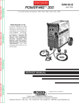
POWER MIG™ 300
February, 2004
For use with machine Code Numbers: 10562, 10952, 10958, 11000, 11097, 11098
For use with machine
Safety Depends on You
Lincoln arc welding and cutting
equipment is designed and built
with safety in mind. However, your
overall safety can be increased by
proper installation ... and thoughtful operation on your part. DO
NOT INSTALL, OPERATE OR
REPAIR THIS EQUIPMENT
WITHOUT READING THIS
MANUAL AND THE SAFETY
PRECAUTIONS CONTAINED
THROUGHOUT. And, most
importantly, think before you act
and be careful.
OPERATOR’S MANUAL
Copyright © 2004 Lincoln Global Inc.
• World's Leader in Welding and Cutting Products •
• Sales and Service through Subsidiaries and Distributors Worldwide •
Cleveland, Ohio 44117-1199 U.S.A. TEL: 216.481.8100 FAX: 216.486.1751 WEB SITE: www.lincolnelectric.com
i
i
SAFETY
WARNING
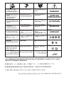
CALIFORNIA PROPOSITION 65 WARNINGS
Diesel engine exhaust and some of its constituents
are known to the State of California to cause cancer, birth defects, and other reproductive harm.
The Above For Diesel Engines
The engine exhaust from this product contains
chemicals known to the State of California to cause
cancer, birth defects, or other reproductive harm.
The Above For Gasoline Engines
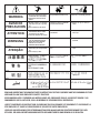
ARC WELDING CAN BE HAZARDOUS. PROTECT YOURSELF AND OTHERS FROM POSSIBLE SERIOUS INJURY OR DEATH.
KEEP CHILDREN AWAY. PACEMAKER WEARERS SHOULD CONSULT WITH THEIR DOCTOR BEFORE OPERATING.
Read and understand the following safety highlights. For additional safety information, it is strongly recommended that you
purchase a copy of “Safety in Welding & Cutting - ANSI Standard Z49.1” from the American Welding Society, P.O. Box
351040, Miami, Florida 33135 or CSA Standard W117.2-1974. A Free copy of “Arc Welding Safety” booklet E205 is available
from the Lincoln Electric Company, 22801 St. Clair Avenue, Cleveland, Ohio 44117-1199.
BE SURE THAT ALL INSTALLATION, OPERATION, MAINTENANCE AND REPAIR PROCEDURES ARE
PERFORMED ONLY BY QUALIFIED INDIVIDUALS.
FOR ENGINE
powered equipment.
1.h. To avoid scalding, do not remove the
radiator pressure cap when the engine is
hot.
1.a. Turn the engine off before troubleshooting and maintenance
work unless the maintenance work requires it to be running.
____________________________________________________
1.b. Operate engines in open, well-ventilated
areas or vent the engine exhaust fumes
outdoors.
____________________________________________________
1.c. Do not add the fuel near an open flame
welding arc or when the engine is running.
Stop the engine and allow it to cool before
refueling to prevent spilled fuel from vaporizing on contact with hot engine parts and
igniting. Do not spill fuel when filling tank. If
fuel is spilled, wipe it up and do not start
engine until fumes have been eliminated.
____________________________________________________
1.d. Keep all equipment safety guards, covers and devices in
position and in good repair.Keep hands, hair, clothing and
tools away from V-belts, gears, fans and all other moving
parts when starting, operating or repairing equipment.
____________________________________________________
1.e. In some cases it may be necessary to remove safety
guards to perform required maintenance. Remove
guards only when necessary and replace them when the
maintenance requiring their removal is complete.
Always use the greatest care when working near moving
parts.
___________________________________________________
1.f. Do not put your hands near the engine fan.
Do not attempt to override the governor or
idler by pushing on the throttle control rods
while the engine is running.
ELECTRIC AND
MAGNETIC FIELDS
may be dangerous
2.a. Electric current flowing through any conductor causes
localized Electric and Magnetic Fields (EMF). Welding
current creates EMF fields around welding cables and
welding machines
2.b. EMF fields may interfere with some pacemakers, and
welders having a pacemaker should consult their physician
before welding.
2.c. Exposure to EMF fields in welding may have other health
effects which are now not known.
2.d. All welders should use the following procedures in order to
minimize exposure to EMF fields from the welding circuit:
2.d.1. Route the electrode and work cables together - Secure
them with tape when possible.
2.d.2. Never coil the electrode lead around your body.
2.d.3. Do not place your body between the electrode and
work cables. If the electrode cable is on your right
side, the work cable should also be on your right side.
2.d.4. Connect the work cable to the workpiece as close as
possible to the area being welded.
___________________________________________________
1.g. To prevent accidentally starting gasoline engines while
turning the engine or welding generator during maintenance
work, disconnect the spark plug wires, distributor cap or
magneto wire as appropriate.
2.d.5. Do not work next to welding power source.
Mar ‘95
ii
ii
SAFETY
ELECTRIC SHOCK can
kill.
3.a. The electrode and work (or ground) circuits
are electrically “hot” when the welder is on.
Do not touch these “hot” parts with your bare
skin or wet clothing. Wear dry, hole-free
gloves to insulate hands.
3.b. Insulate yourself from work and ground using dry insulation.
Make certain the insulation is large enough to cover your full
area of physical contact with work and ground.
In addition to the normal safety precautions, if welding
must be performed under electrically hazardous
conditions (in damp locations or while wearing wet
clothing; on metal structures such as floors, gratings or
scaffolds; when in cramped positions such as sitting,
kneeling or lying, if there is a high risk of unavoidable or
accidental contact with the workpiece or ground) use
the following equipment:
• Semiautomatic DC Constant Voltage (Wire) Welder.
• DC Manual (Stick) Welder.
• AC Welder with Reduced Voltage Control.
3.c. In semiautomatic or automatic wire welding, the electrode,
electrode reel, welding head, nozzle or semiautomatic
welding gun are also electrically “hot”.
3.d. Always be sure the work cable makes a good electrical
connection with the metal being welded. The connection
should be as close as possible to the area being welded.
3.e. Ground the work or metal to be welded to a good electrical
(earth) ground.
3.f. Maintain the electrode holder, work clamp, welding cable and
welding machine in good, safe operating condition. Replace
damaged insulation.
3.g. Never dip the electrode in water for cooling.
3.h. Never simultaneously touch electrically “hot” parts of
electrode holders connected to two welders because voltage
between the two can be the total of the open circuit voltage
of both welders.
3.i. When working above floor level, use a safety belt to protect
yourself from a fall should you get a shock.
3.j. Also see Items 6.c. and 8.
ARC RAYS can burn.
4.a. Use a shield with the proper filter and cover
plates to protect your eyes from sparks and
the rays of the arc when welding or observing
open arc welding. Headshield and filter lens
should conform to ANSI Z87. I standards.
4.b. Use suitable clothing made from durable flame-resistant
material to protect your skin and that of your helpers from
the arc rays.
4.c. Protect other nearby personnel with suitable, non-flammable
screening and/or warn them not to watch the arc nor expose
themselves to the arc rays or to hot spatter or metal.
FUMES AND GASES
can be dangerous.
5.a. Welding may produce fumes and gases
hazardous to health. Avoid breathing these
fumes and gases.When welding, keep
your head out of the fume. Use enough
ventilation and/or exhaust at the arc to keep
fumes and gases away from the breathing zone. When
welding with electrodes which require special
ventilation such as stainless or hard facing (see
instructions on container or MSDS) or on lead or
cadmium plated steel and other metals or coatings
which produce highly toxic fumes, keep exposure as
low as possible and below Threshold Limit Values (TLV)
using local exhaust or mechanical ventilation. In
confined spaces or in some circumstances, outdoors, a
respirator may be required. Additional precautions are
also required when welding on galvanized steel.
5.b. Do not weld in locations near chlorinated hydrocarbon vapors
coming from degreasing, cleaning or spraying operations.
The heat and rays of the arc can react with solvent vapors to
form phosgene, a highly toxic gas, and other irritating products.
5.c. Shielding gases used for arc welding can displace air and
cause injury or death. Always use enough ventilation,
especially in confined areas, to insure breathing air is safe.
5.d. Read and understand the manufacturer’s instructions for this
equipment and the consumables to be used, including the
material safety data sheet (MSDS) and follow your
employer’s safety practices. MSDS forms are available from
your welding distributor or from the manufacturer.
5.e. Also see item 1.b.
Mar ‘95
iii
4
SAFETY
WELDING SPARKS can
cause fire or explosion.
6.a. Remove fire hazards from the welding area.
If this is not possible, cover them to prevent
the welding sparks from starting a fire.
Remember that welding sparks and hot
materials from welding can easily go through small cracks
and openings to adjacent areas. Avoid welding near
hydraulic lines. Have a fire extinguisher readily available.
6.b. Where compressed gases are to be used at the job site,
special precautions should be used to prevent hazardous
situations. Refer to “Safety in Welding and Cutting” (ANSI
Standard Z49.1) and the operating information for the
equipment being used.
6.c. When not welding, make certain no part of the electrode
circuit is touching the work or ground. Accidental contact
can cause overheating and create a fire hazard.
6.d. Do not heat, cut or weld tanks, drums or containers until the
proper steps have been taken to insure that such procedures
will not cause flammable or toxic vapors from substances
inside. They can cause an explosion even though they have
been “cleaned”. For information, purchase “Recommended
Safe Practices for the Preparation for Welding and Cutting of
Containers and Piping That Have Held Hazardous
Substances”, AWS F4.1 from the American Welding Society
(see address above).
6.e. Vent hollow castings or containers before heating, cutting or
welding. They may explode.
6.f. Sparks and spatter are thrown from the welding arc. Wear oil
free protective garments such as leather gloves, heavy shirt,
cuffless trousers, high shoes and a cap over your hair. Wear
ear plugs when welding out of position or in confined places.
Always wear safety glasses with side shields when in a
welding area.
6.g. Connect the work cable to the work as close to the welding
area as practical. Work cables connected to the building
framework or other locations away from the welding area
increase the possibility of the welding current passing
through lifting chains, crane cables or other alternate circuits. This can create fire hazards or overheat lifting chains
or cables until they fail.
6.h. Also see item 1.c.
iii
CYLINDER may explode
if damaged.
7.a. Use only compressed gas cylinders
containing the correct shielding gas for the
process used and properly operating
regulators designed for the gas and
pressure used. All hoses, fittings, etc. should be suitable for
the application and maintained in good condition.
7.b. Always keep cylinders in an upright position securely
chained to an undercarriage or fixed support.
7.c. Cylinders should be located:
• Away from areas where they may be struck or subjected to
physical damage.
• A safe distance from arc welding or cutting operations and
any other source of heat, sparks, or flame.
7.d. Never allow the electrode, electrode holder or any other
electrically “hot” parts to touch a cylinder.
7.e. Keep your head and face away from the cylinder valve outlet
when opening the cylinder valve.
7.f. Valve protection caps should always be in place and hand
tight except when the cylinder is in use or connected for
use.
7.g. Read and follow the instructions on compressed gas
cylinders, associated equipment, and CGA publication P-l,
“Precautions for Safe Handling of Compressed Gases in
Cylinders,” available from the Compressed Gas Association
1235 Jefferson Davis Highway, Arlington, VA 22202.
FOR ELECTRICALLY
powered equipment.
8.a. Turn off input power using the disconnect
switch at the fuse box before working on
the equipment.
8.b. Install equipment in accordance with the U.S. National
Electrical Code, all local codes and the manufacturer’s
recommendations.
8.c. Ground the equipment in accordance with the U.S. National
Electrical Code and the manufacturer’s recommendations.
Mar ‘95
iv
iv
SAFETY
PRÉCAUTIONS DE SÛRETÉ
Pour votre propre protection lire et observer toutes les instructions
et les précautions de sûreté specifiques qui parraissent dans ce
manuel aussi bien que les précautions de sûreté générales suivantes:
Sûreté Pour Soudage A L’Arc
1. Protegez-vous contre la secousse électrique:
a. Les circuits à l’électrode et à la piéce sont sous tension
quand la machine à souder est en marche. Eviter toujours
tout contact entre les parties sous tension et la peau nue
ou les vétements mouillés. Porter des gants secs et sans
trous pour isoler les mains.
b. Faire trés attention de bien s’isoler de la masse quand on
soude dans des endroits humides, ou sur un plancher
metallique ou des grilles metalliques, principalement dans
les positions assis ou couché pour lesquelles une grande
partie du corps peut être en contact avec la masse.
c. Maintenir le porte-électrode, la pince de masse, le câble
de soudage et la machine à souder en bon et sûr état
defonctionnement.
d.Ne jamais plonger le porte-électrode dans l’eau pour le
refroidir.
e. Ne jamais toucher simultanément les parties sous tension
des porte-électrodes connectés à deux machines à souder
parce que la tension entre les deux pinces peut être le
total de la tension à vide des deux machines.
f. Si on utilise la machine à souder comme une source de
courant pour soudage semi-automatique, ces precautions
pour le porte-électrode s’applicuent aussi au pistolet de
soudage.
2. Dans le cas de travail au dessus du niveau du sol, se protéger
contre les chutes dans le cas ou on recoit un choc. Ne jamais
enrouler le câble-électrode autour de n’importe quelle partie
du corps.
3. Un coup d’arc peut être plus sévère qu’un coup de soliel,
donc:
a. Utiliser un bon masque avec un verre filtrant approprié
ainsi qu’un verre blanc afin de se protéger les yeux du rayonnement de l’arc et des projections quand on soude ou
quand on regarde l’arc.
b. Porter des vêtements convenables afin de protéger la
peau de soudeur et des aides contre le rayonnement de
l‘arc.
c. Protéger l’autre personnel travaillant à proximité au
soudage à l’aide d’écrans appropriés et non-inflammables.
4. Des gouttes de laitier en fusion sont émises de l’arc de
soudage. Se protéger avec des vêtements de protection libres
de l’huile, tels que les gants en cuir, chemise épaisse, pantalons sans revers, et chaussures montantes.
5. Toujours porter des lunettes de sécurité dans la zone de
soudage. Utiliser des lunettes avec écrans lateraux dans les
zones où l’on pique le laitier.
6. Eloigner les matériaux inflammables ou les recouvrir afin de
prévenir tout risque d’incendie dû aux étincelles.
7. Quand on ne soude pas, poser la pince à une endroit isolé de
la masse. Un court-circuit accidental peut provoquer un
échauffement et un risque d’incendie.
8. S’assurer que la masse est connectée le plus prés possible
de la zone de travail qu’il est pratique de le faire. Si on place
la masse sur la charpente de la construction ou d’autres
endroits éloignés de la zone de travail, on augmente le risque
de voir passer le courant de soudage par les chaines de levage, câbles de grue, ou autres circuits. Cela peut provoquer
des risques d’incendie ou d’echauffement des chaines et des
câbles jusqu’à ce qu’ils se rompent.
9. Assurer une ventilation suffisante dans la zone de soudage.
Ceci est particuliérement important pour le soudage de tôles
galvanisées plombées, ou cadmiées ou tout autre métal qui
produit des fumeés toxiques.
10. Ne pas souder en présence de vapeurs de chlore provenant
d’opérations de dégraissage, nettoyage ou pistolage. La
chaleur ou les rayons de l’arc peuvent réagir avec les vapeurs
du solvant pour produire du phosgéne (gas fortement toxique)
ou autres produits irritants.
11. Pour obtenir de plus amples renseignements sur la sûreté,
voir le code “Code for safety in welding and cutting” CSA
Standard W 117.2-1974.
PRÉCAUTIONS DE SÛRETÉ POUR
LES MACHINES À SOUDER À
TRANSFORMATEUR ET À
REDRESSEUR
1. Relier à la terre le chassis du poste conformement au code de
l’électricité et aux recommendations du fabricant. Le dispositif
de montage ou la piece à souder doit être branché à une
bonne mise à la terre.
2. Autant que possible, I’installation et l’entretien du poste seront
effectués par un électricien qualifié.
3. Avant de faires des travaux à l’interieur de poste, la debrancher à l’interrupteur à la boite de fusibles.
4. Garder tous les couvercles et dispositifs de sûreté à leur
place.
Mar. ‘93
v
v
Thank You
for selecting a QUALITY product by Lincoln Electric. We want you
to take pride in operating this Lincoln Electric Company product
••• as much pride as we have in bringing this product to you!
Please Examine Carton and Equipment For Damage Immediately
When this equipment is shipped, title passes to the purchaser upon receipt by the carrier. Consequently, Claims
for material damaged in shipment must be made by the purchaser against the transportation company at the
time the shipment is received.
Please record your equipment identification information below for future reference. This information can be
found on your machine nameplate.
Product _________________________________________________________________________________
Model Number ___________________________________________________________________________
Code Number or Date Code_________________________________________________________________
Serial Number____________________________________________________________________________
Date Purchased___________________________________________________________________________
Where Purchased_________________________________________________________________________
Whenever you request replacement parts or information on this equipment, always supply the information you
have recorded above. The code number is especially important when identifying the correct replacement parts.
On-Line Product Registration
- Register your machine with Lincoln Electric either via fax or over the Internet.
• For faxing: Complete the form on the back of the warranty statement included in the literature packet
accompanying this machine and fax the form per the instructions printed on it.
• For On-Line Registration: Go to our WEB SITE at www.lincolnelectric.com. Choose “Quick Links” and then
“Product Registration”. Please complete the form and submit your registration.
Read this Operators Manual completely before attempting to use this equipment. Save this manual and keep it
handy for quick reference. Pay particular attention to the safety instructions we have provided for your protection.
The level of seriousness to be applied to each is explained below:
WARNING
This statement appears where the information must be followed exactly to avoid serious personal injury or
loss of life.
CAUTION
This statement appears where the information must be followed to avoid minor personal injury or damage to
this equipment.
vi
TABLE OF CONTENTS
Page
________________________________________________________________________
Installation.......................................................................................................................Section A
Technical Specifications.......................................................................................................A-1
Safety Precautions ...............................................................................................................A-2
Uncrating the POWER MIG 300...........................................................................................A-2
Location................................................................................................................................A-2
Input Power, Grounding and Connection Diagrams .....................................................A-2, A-3
Gun and Cable Installation ...................................................................................................A-4
Shielding Gas .........................................................................................................A-4 thru A-5
________________________________________________________________________________
Operation.........................................................................................................................Section B
Safety Precautions ...............................................................................................................B-1
Definition Of Welding Modes...............................................................................................B-1
Common Welding Abbreviations ..........................................................................................B-1
Product Description ..............................................................................................................B-2
Controls and Settings ...................................................................................................B-2, B-3
Setting and Configuring the POWER MIG 300 for welding ..................................................B-4
Multi-Process Panel Functions .....................................................................................B-5, B-6
Wire Drive Roll .....................................................................................................................B-7
Procedure for Changing Drive and Idle Roll Sets................................................................B-8
Wire Reel Loading................................................................................................................B-8
Mounting of 10 to 44 lbs. Spools ..........................................................................................B-8
Feeding Wire Electrode........................................................................................................B-9
Idle Roll Pressure Setting.....................................................................................................B-9
Avoiding Wire Feeding Problems .........................................................................................B-9
Special Welding Processes Available ................................................................................B-10
Pulse On Pulse, and Benefits of Pulse On Pulse...............................................................B-11
Power Mode .......................................................................................................................B-12
________________________________________________________________________________
Accessories ....................................................................................................................Section C
Drive Roll Kits.......................................................................................................................C-1
Aluminum Feeding Kit .........................................................................................................C-1
Readi-Reel Adapter..............................................................................................................C-1
Dual Cylinder Mounting Kit...................................................................................................C-1
Alternative Magnum GMAW Gun and Cable Assemblies ....................................................C-1
Magnum Gun Connection Kit ..............................................................................................C-1
Spool Gun PrinceTM XL.........................................................................................................C-1
Push-Pull Feeding Connection Adapter Kit..........................................................................C-2
Making a Weld with the Prince XL or Cobra Gold Torch Installed .......................................C-2
________________________________________________________________________________
Maintenance....................................................................................................................Section D
Safety Precautions, General Maintenance...........................................................................D-1
Drive Rolls and Guide Plates ...............................................................................................D-1
Contact Tip and Gas Nozzle Installation ..............................................................................D-1
Gun Tubes and Nozzles, Gun Cable Cleaning ....................................................................D-1
Liner Removal and Replacement.........................................................................................D-2
________________________________________________________________________________
Troubleshooting .............................................................................................................Section E
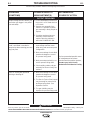
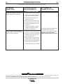
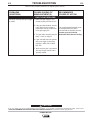
How to Use Troubleshooting Guide .....................................................................................E-1
Troubleshooting .....................................................................................................E-2 thru E-5
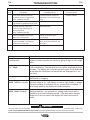
Fault Codes ..........................................................................................................................E-6
Push / Pull Gun Wire Feeder Troubleshooting ....................................................E-7 thru E-10
________________________________________________________________________________
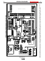
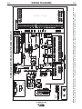
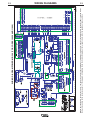
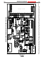
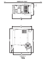
Diagrams..........................................................................................................................Section F
Wiring Diagrams and Dimension Print ...................................................................F-1 thru F-5
________________________________________________________________________________
Parts Manual ...................................................................................................................Appendix
POWER MIG 300 Parts Pages .............................................................................P409 Series
Magnum 300 & 400 GMAW Gun, Connector Assembly.....................................P202-C Series
________________________________________________________________________________
vi
A-1
A-1
INSTALLATION
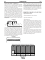
TECHNICAL SPECIFICATIONS – POWER MIG 300
INPUT – SINGLE PHASE ONLY
Standard Voltage/Frequency
208/230/460/575/60 Hz
Input Current @ 230Amp Rated Output Input Current @ 300 Amp Rated Output
48/43/22/17 Amps
72/62/31/25 Amps
RATED OUTPUT
Input Voltage
208
230/460/575
208/230/460/575
Duty Cycle
40%
60%
100%
Amps
300 Amps
300 Amps
230Amps
Volts at Rated Amperes
32 Volts
32 Volts
29 Volts
OUTPUT
Welding Current Range (Continuous)
5 – 350 Amps
Maximum Open Circuit Voltage
67 Volts
Welding Voltage Range
10-45 Volts
RECOMMENDED INPUT WIRE AND FUSE SIZES - SINGLE PHASE
Input Voltage/
230Amps @
300Amps @
75°C Copper Wire
Fuse
Frequency (Hz)
29 Volts
32 Volts
AWG (IEC)
or
(100% Duty Cycle)
(60% Duty Cycle)
Sizes (MM2)
Breaker Size
48 A
43 A
22 A
17 A
72 A
62 A
31 A
25 A
6 (16 mm2)
6 (16 mm2)
10 (6 mm2)
12 (2.5 mm2)
208/60*
230/60
460/60
575/60
90 A
80 A
50 A
35 A
NOTE: Use #10 AWG Grounding Wire
*For 208V Input ONLY: The duty Cycle Rating at 300 Amps is 40%
PHYSICAL DIMENSIONS
Height
31.79 in
808 mm
Width
18.88 in
480 mm
Depth
38.78 in
985 mm
Weight
255 Ibs
116 kg
WIRE SPEED RANGE
Wire Speed
50 – 700 IPM (1.27 – 17.8 m/minute)
POWER MIG 300
A-2
INSTALLATION
Read entire installation section before starting
installation.
SAFETY PRECAUTIONS
A-2
ONLY QUALIFIED PERSONNEL SHOULD
INSTALL, USE OR SERVICE THIS EQUIPMENT.
UNCRATING THE POWER MIG 300
WARNING
ELECTRIC SHOCK can kill.
• Do not touch electrically live
parts or electrode with skin or
wet clothing.
• Insulate yourself from work and
ground.
• Always wear dry insulating
gloves.
• Do not use AC welder if your
clothing, cloves or work area is
damp or if working on, under or
inside work piece.
Use the following equipment:
- Semiautomatic DC constant voltage (wire) welder.
- DC manual (stick) welder.
- AC welder with reduced voltage
control.
• Do not operate with panels
removed.
• Disconnect input power before
servicing.
FUMES AND GASES can be
dangerous.
• Keep your head out of fumes.
• Use ventilation or exhaust to
remove fumes from breathing
zone and general area.
WELDING SPARKS can
cause fire or explosion.
Cut banding and lift off cardboard carton. Cut banding
holding the machine to the skid. Remove foam and
corrugated packing material. Untape accessories from
Gas Bottle Platform. Unscrew the two wood screws
(at the Gas Bottle Platform) holding the machine to
the skid. Roll the machine off the skid assembly.
LOCATION
Locate the welder in a dry location where there is free
circulation of clean air into the louvers in the back and
out the front. A location that minimizes the amount of
smoke and dirt drawn into the rear louvers reduces
the chance of dirt accumulation that can block air passages and cause overheating.
INPUT POWER, GROUNDING AND
CONNECTION DIAGRAMS
1. Before starting the installation, check with the local
power company if there is any question about
whether your power supply is adequate for the voltage, amperes, phase, and frequency specified on
the welder nameplate. Also be sure the planned
installation will meet the U.S. National Electrical
Code and local code requirements. This welder
may be operated from a single phase line or from
one phase of a two or three phase line.
2. The POWER MIG 300 is supplied connected for
230 Volt Input. If the welder is to be operated on
another voltage, it must be reconnected according
to the instructions in Figure A.1
• Keep flammable material away.
• Do not weld on closed containers.
ARC RAYS can burn eyes
and skin.
• Wear eye, ear and body protection.
Observe all safety information throughout this manual.
-----------------------------------------------------------
POWER MIG 300
A-3
A-3
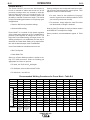
INSTALLATION
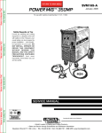
FIGURE A.1 — Triple Voltage Machine Input Connections
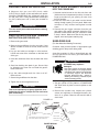
3. The POWER MIG is shipped with a 10ft.(3.05m)
input cable and plug connected to the welder.
Using the instructions in Figure A.2, have a qualified electrician connect the receptacle or cable to
the input power lines and the system ground per
the U.S. National Electrical Code and any applicable local codes. See “Technical Specifications” at
the beginning of this chapter for proper wire sizes.
For long runs over 100ft. (30.48m), larger copper
wires should be used. Fuse the two hot lines with
super lag type fuses as shown in the following diagram. The center contact in the receptacle is for the
grounding connection. A green wire in the input
cable connects this contact to the frame of the
welder. This ensures proper grounding of the
welder frame when the welder plug is inserted into
the receptacle.
POWER MIG 300
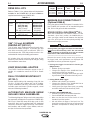
FIGURE A.2 — Receptacle Diagram
CONNECT TO A SYSTEM
GROUNDING WIRE. SEE
THE UNITED STATES
NATIONAL ELECTRICAL
CODE AND/OR LOCAL
CODES FOR OTHER
DETAILS AND MEANS FOR
PROPER GROUNDING.
CONNECT TO HOT WIRES
OF A THREE-WIRE, SINGLE
PHASE SYSTEM OR TO ONE
PHASE OF A TWO OR
THREE PHASE SYSTEM.
A-4
A-4
INSTALLATION
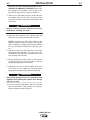
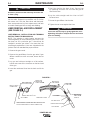
GUN AND CABLE INSTALLATION
A Magnum 300 gun and 15Ft.(4.6m) cable
(12Ft.(3.7m) for Codes 11000 and below) are provided with the POWER MIG 300. A Magnum cable liner
for .035-.045" (0.9-1.2 mm) electrode and contact tips
for .035” (0.9mm) and .045” (1.2mm) are included for
15Ft..
GUN & CABLE ASSEMBLY INSTALLED
INTO THE POWER MIG
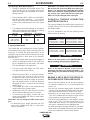
LINER INSTALLATION AND TRIMMING
INSTRUCTION (SEE FIGURE A.3)
1. Unscrew knurled screw on the drive unit front end
(inside wire feed compartment) until tip of screw no
longer protrudes into gun opening as seen from
front of machine.
2. Insert the male end of gun cable into the female
casting through opening in front panel. Make sure
connector is fully inserted and tighten knurled
screw.
3. Connect the gun trigger connector from the gun
and cable to the mating receptacle inside the compartment located above the gun connection made
in step 2 above. Make sure that the key ways are
aligned, insert and tighten retaining ring.
1. Remove the gas nozzle.
SHIELDING GAS
WARNING
Turn the welder power switch off before installing
gun and cable.
(For Gas Metal Arc Welding Processes)
2. Remove the gas diffuser from the gun tube. If gas
diffuser contains a small set screw, loosen the set
screw.
3. Lay gun and cable out straight on a flat surface.
Loosen set screw of the connector on the back end
of the gun.
Customer must provide cylinder of appropriate type
shielding gas for the process being used.
A gas flow regulator, for CO2 or Argon blend gas, and
an inlet gas hose are factory provided with the
POWER MIG 300.
4. Insert the untrimmed Liner into the back end of the
gun.
WARNING
CYLINDER may explode if
damaged.
5. Seat Liner bushing into back of gun. Secure Liner
by tightening set screw. Do not install the gas diffuser at this time.
• Gas under pressure is explosive. Always
keep gas cylinders in an upright position
and always keep chained to undercarriage
or stationary support. See American
National Standard Z-49.1, “Safety in
Welding and Cutting” published by the
American Welding Society.
6. Lay the cable straight and trim Liner to 9/16”.
Remove burrs.
7. Secure the gas diffuser into the tube.
Install shielding gas supply as follows:
1. Set gas cylinder on rear platform of POWER MIG
300. Hook chain in place to secure cylinder to rear
of welder.
8. Tighten the set screw against the Liner.
CAUTION
This screw should only be gently tightened. Over
tightening will split or collapse the liner and cause
poor wire feeding.
------------------------------------------------------------------------
2. Remove the cylinder cap. Inspect the cylinder
valves and regulator for damaged threads, dirt,
dust, oil or grease. Remove dust and dirt with a
clean cloth.
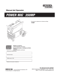
FIGURE A.3
INSULATION TUBE
FEEDR END
CABLE HANDLE
GUN HANDLE
GUN TUBE
BRASS CABLE
CONNECTOR
MOLDED GAS PLUG
SET SCREW
SET SCREW
CLAMPING SCREW
GAS DIFFUSER
LINER ASSEMBLY (LINER BUSHING TO BE SEATED
TIGHT AGIANST BRASS CABLE CONNECTOR)
NOZZLE INSULATION
GAS NOZZLE
POWER MIG 300
9/16 (14.3mm)
LINER TRIM
LENGTH
A-5
INSTALLATION
DO NOT ATTACH THE REGULATOR IF OIL,
GREASE OR DAMAGE IS PRESENT! Inform your
gas supplier of this condition. Oil or grease in the
presence of high pressure oxygen is explosive.
3. Stand to one side away from the outlet and open
the cylinder valve for an instant. This blows away
any dust or dirt which may have accumulated in the
valve outlet.
WARNING
Be sure to keep your face away from the valve
outlet when “cracking” the valve.
4. Attach the flow regulator to the cylinder valve and
tighten the union nut(s) securely with a wrench.
NOTE: If connecting to 100% CO2 cylinder, insert
regulator adapter between regulator and cylinder
valve. If adapter is equipped with a plastic washer,
be sure it is seated for connection to the CO2 cylinder.
5. Attach one end of the inlet gas hose to the outlet
fitting of the flow regulator, the other end to the
POWER MIG 300 rear fitting, and tighten the union
nuts securely with a wrench.
6. Before opening the cylinder valve, turn the regulator adjusting knob counterclockwise until the
adjusting spring pressure is released.
7. Standing to one side, open the cylinder valve slowly a fraction of a turn. When the cylinder pressure
gauge pointer stops moving, open the valve fully.
WARNING
Never stand directly in front of or behind the flow
regulator when opening the cylinder valve. Always
stand to one side.
-----------------------------------------------------------------------8. The flow regulator is adjustable. Adjust it to the flow
rate recommended for the procedure and process
being used before making the weld.
POWER MIG 300
A-5
B-1
OPERATION
Read entire Operation section before
operating the POWER MIG 300.
WARNING
COMMON WELDING ABBREVIATIONS
ELECTRIC SHOCK can kill.
WFS
• Wire Feed Speed
• Do not touch electrically live
parts or electrode with skin or
wet clothing. Insulate yourself
from work and ground.
CC
• Constant Current
• Always wear dry insulating
gloves.
CV
• Constant Voltage
FUMES AND GASES can be
dangerous.
GMAW (MIG)
• Gas Metal Arc welding
• Keep your head out of fumes.
GMAW-P (MIG)
• Gas Metal Arc welding-(Pulse)
• Use ventilation or exhaust to
remove fumes from breathing
zone.
WELDING SPARKS can
cause fire or explosion.
• Keep flammable material away.
B-1
GMAW-PP (MIG)
• Gas Metal Arc welding-(Pulse-on-Pulse)
GTAW (TIG)
• Gas Tungsten Arc welding
• Do not weld on closed containers.
SMAW (STICK)
• Shielded Metal Arc welding
ARC RAYS can burn eyes
and skin.
FCAW (INNERSHIELD)
• Flux Core Arc Welding
• Wear eye, ear and body protection.
Observe all safety information throughout
this manual.
DEFINITIONS OF WELDING MODES
NON-SYNERGIC WELDING MODES
• A Non-synergic welding mode requires all welding
process variables to be set by the operator.
SYNERGIC WELDING MODES
• A Synergic welding mode offers the simplicity of
single knob control. The machine will select the correct voltage and amperage based on the wire feed
speed (WFS) set by the operator.
POWER MIG 300
B-2
OPERATION
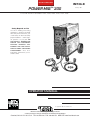
PRODUCT DESCRIPTION
The POWER MIG 300 is a complete semiautomatic
multi-process DC arc welding machine offering CV
and CC DC welding. It is rated for 300 amps, 32 volts
at a 60% duty cycle. The standard machine is
equipped to weld CC-Stick, CC-GTAW, CV-FCAW,
and synergic and non-synergic CV-GMAW / GMAW-P
and Pulse-on-Pulse and Power Mode welding
processes. See the descriptions for Pulse on
Pulse™and Power Mode welding processes later in
this section.
Mode #5 and mode #6 are non-synergic CV GMAW
modes for bare and flux cored wires, respectively. In
these modes, the user presets the wire feed speed
(WFS) on the left meter and the welding voltage on
the right. These two settings are independent; that is,
if the WFS is changed the voltage will remain constant, or vice versa.
All of the other mode numbers designated as "CV" are
synergic. Again, WFS is shown on the left meter and
voltage is shown on the right meter. However, in using
these modes, the WFS is preset and the voltage is
preset only once. Now, when the WFS is changed, the
voltage will change with it, so that the arc appearance
and arc length will stay the same without the necessity
to re-adjust the voltage.
The modes shown as "GMAW-P" or " GMAW-PP" are
all synergic pulsed modes. In these modes WFS is
shown on the left meter and "Trim" is shown on the
right meter. The user adjusts WFS to obtain an arc
with the correct arc energy for the material thickness
being welded. The Trim, which is adjustable from values of –1.5 to 0 (OFF) and up to +1.5 controls the arc
length. Higher values of Trim give longer arc lengths.
Once the user has adjusted the Trim for one WFS, the
power supply will synergically change many variables
so that, as the WFS is changed, the arc length and
arc appearance will remain the same. The synergic
modes are usable with both push and push – pull
torches, as described later in this Manual. When using
a spool gun, however, although the synergic pulsed
modes are still accessible, they must be used in a
non-synergic manner as described in the Accessory
Section.
B-2
Other features
Optional kits are available for push-pull welding, spool
gun operation, push feeding of 3/64 aluminum with the
standard POWER MIG 300 gun and wire feeder. A
Dual Cylinder Mounting Kit is also offered.
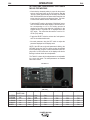
CONTROLS AND SETTINGS
(See Figure B.1)
1. WIRE FEED SPEED (WFS) / AMP METER - This
meter displays either the WFS or current value
(Amps) depending on the status of the machine.
Located below the display is the text "WFS" and
"Amps." An LED light is illuminated to the left of one
of these units to indicate the units of the value displayed on the meter.
• Prior to CV operation, the meter displays the
desired preset WFS value.
• Prior to CC-Stick and CC-GTAW operation, the
meter displays the preset current value.
• During Welding, the meter displays actual average
amps.
• After welding, the meter holds the actual current
value for 5 seconds. During this time, the display
is blinking to indicate that the machine is in the
"Hold" period. Output adjustment while in the
"Hold" period results in the "prior to operation"
characteristics stated above.
• After the 5 second "Hold" period, the meter displays the set WFS (CV modes) or Amp (CC
modes) value.
The digital microcomputer based control system
allows easy and accurate adjustment of weld parameters through the multi-process panel located on the
front of the machine. The POWER MIG 300 is
equipped with a 6-pin and 7-pin connector to allow
operation of a push-pull gun for feeding aluminum
wires, a spool gun, remotes, and a foot amptrol.
POWER MIG 300
Figure B.1
B-3
B-3
OPERATIONS
2. VOLT / TRIM METER - This meter displays either
the voltage or trim value depending on the status of
the machine. Located below the display is the text
"Volts" and "Trim." An LED light is illuminated to
the left of one of these in order to indicate the units
of the value displayed in the meter.
5. MULTI-PROCESS PANEL - This panel enables selection
of weld modes as well as adjustment of certain weld
parameters within each weld mode.
CV Processes
• Prior to GMAW and FCAW operation, the meter
displays the desired preset Voltage value.
• Prior to synergic GMAW-P and GMAW-PP operation, the meter displays the desired preset Trim
value. Trim adjusts the synergic default voltage
as a percentage of that voltage. A trim value of 1
is the default and results in the recommended
voltage setting for a given wire feed speed.
Adjusting trim to a value of .95, adjusts the voltage to 95% of the recommended voltage.
• During Welding, the meter displays actual average volts.
• After welding, the meter holds the actual voltage
value for 5 seconds. During this time , the display
is blinking to indicate that the machine is in the
"Hold" period. Output adjustment while in the
"Hold" period results in the "prior to operation"
characteristics stated above.
• Weld Mode (Process selection choices)
• Preflow / Postflow
• Run-In
Choice of weld parameters
• Start
that can be adjusted.
• Arc Control
Complete descriptions of
• Crater
each parameter are found
• Burnback
later in this section.
• Spot
Only one LED will be illuminated at any time. The Weld
Mode attribute will always be a valid selection (the other
attributes may not be available in all processes).
• After the 5 second "Hold" period, the meter displays the set Voltage (GMAW, FCAW) or Trim
(GMAW-P) value.
CC Processes
• The meter displays the status of the output.
• When output is enabled, the meter will display "ON."
• When there is no output, the meter will display "OFF."
3. OUTPUT CONTROLS - The POWER MIG 300 has 2
encoder knobs to adjust weld parameters.
The eight discrete LED’s are used to identify which selection will be shown on the display. The possible selections
are:
}
5A. SELECT Toggle Switch
• This switch toggles through the 8 selections detailed
above the switch.
• A red LED is located next to each possible selection
and is illuminated when that choice can be changed.
5B. Display Meter
• This meter displays the active weld mode (a set of
weld parameters that have been determined to provide the recommended results for a particular welding
process) when the “Weld Mode” LED is illuminated or
when any one of the other seven LED’s is illuminated
the meter indicates what value that welding parameter has been set to.
5C. SET Toggle Switch
• This switch adjusts (up or down) the value shown on
the display meter. When the WELD MODE LED is illuminated, this switch is changing the weld mode of the
machine. The most commonly used modes are displayed in the chart on the right half of the MultiProcess Panel.
If the LED next to a weld parameter
(Preflow/Postflow, Run-In, Start, etc.) is illuminated,
the SET switch will adjust the setting of that specific
weld parameter. The setting is shown on the display
meter.
• Each encoder changes the displayed value of the meter
located directly above that encoder.
• In CC-GTAW modes, the left encoder sets the maximum welding current. Full depression of a foot or hand
amptrol results in the preset level of current.
6. ON/OFF POWER SWITCH
• In CC-Stick and CC-GTAW, the right encoder activates
and de-activates the output. Turning the encoder clockwise enables the output if not using a remote trigger
device. To de-energize the output, turn the encoder
counter-clockwise. The display above will indicate the
"ON" or "OFF" status of the output.
4. THERMAL - This status light illuminates when the power
source has been driven into thermal overload.
POWER MIG 300
B-4
B-4
OPERATION
SETTING AND CONFIGURING THE POWER
MIG 300 FOR WELDING
• Check that the electrode polarity is correct for the process
and turn the Power Switch to the "ON" position. After the
"boot-up" period (approximately 20 seconds), the POWER
MIG 300 will default to the last preset weld mode that was
active when the machine was powered down. The MultiProcess Panel defaults with the "Weld Mode" active.
• Toggle the SET switch to the desired "Weld Mode" operation. The Multi-Process Meter displays a weld mode number corresponding to a CC or CV welding process as
detailed by the chart on the right side of the panel. In the
example shown in Figure B.2 “3” is displayed above the
SET switch. This means that the machine is set for CCGTAW (TIG) welding.
• Toggle the SELECT switch to activate the "weld parameters" for the selected weld mode.
• Set each parameter using the SET switch to adjust the
parameter displayed on the display meter.
NOTE: If the LED next to the weld parameter is flashing, the
WFS/AMP and/or the Volt/Trim values can also be adjusted
for that parameter using the control knobs below each display meter. An LED below each of the displays will also be
flashing to indicate which value is adjustable.
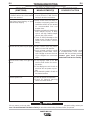
The Table B.1 shows which weld parameters are adjustable
for a given weld mode. The weld parameters are detailed
later in this section.
FIGURE B.2
3
TABLE B.1
CC-STICK
CC-GTAW
CV-FCAW
CV-GMAW
CV-GMAW-P
POWER
PREFLOW /
POSTFLOW
----Yes
----Yes
Yes
Yes
RUN IN
--------Yes
Yes
Yes
Yes
START ARC CONTROL
Yes
Yes
Yes
Yes
Yes
Yes
Yes
----Yes
Yes
Yes
Yes
POWER MIG 300
CRATER
BURNBACK
SPOT
--------Yes
Yes
Yes
Yes
--------Yes
Yes
Yes
Yes
--------Yes
Yes
Yes
Yes
B-5
OPERATION
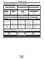
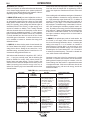
MULTI-PROCESS PANEL FUNCTIONS
Weld Mode
Setting the Weld Mode is selecting the proper program
from the ones available in the machine’s memory for a
particular welding application. The table on the right side
of the front panel (See Figure B.2) gives information on
the different programs available in this machine. It
describes the type of process (CV, CC, synergic
GMAW), type of metal (mild steel, stainless steel, aluminum), type of shielding gas and size of electrode recommended for a particular mode.
The Weld Mode selection is enabled by toggling the
SELECT switch until the LED next to Weld Mode is lit. A
Weld Mode number will be displayed on the display
meter. Toggling the SET switch up or down will increase
or decrease the WELD MODE number displayed. The
machine will change to the selected weld mode after two
seconds of SET switch inactivity. If the SELECT switch is
changed before two seconds of SET switch inactivity, the
machine will not change modes. The last active Weld
Mode will be saved at power down so that it will be
selected with the next power up of the machine.
Preflow / Postflow
• The Preflow setting allows a time to be selected for
shielding gas to flow after the trigger is pulled and prior
to wire feeding and establishing an arc.
• The Postflow setting allows a time to be selected for
shielding gas to continue to flow after the trigger is
released and output current is turned off.
• The Preflow timer will be selected by toggling the
SELECT switch until the LED next to PREFLOW
/POSTFLOW is lit. The display meter will read Pre. The
present Preflow time will be displayed and can be
changed by positioning the SET switch up or down.
• The Postflow timer will be selected by pressing down
the SELECT switch an additional time. The LED next
to PREFLOW / POSTFLOW will remain lit; but the display meter will now read Pos. The present Postflow
time will be displayed and can be changed by positioning the SET switch up or down.
• The default value for both Preflow and Postflow is
"OFF" (0 seconds).
• Preflow can be adjusted from 0 to 2.5 seconds in 0.1
second increments.
• Postflow can be adjusted from 0 to 10.0 seconds in 0.1
second increments.
B-5
Run-In
• The Run-In function offers the ability to set a wire feed
speed, from trigger until an arc is established, that is independent of the Welding or Start wire feed speed. Setting a
Run-In WFS lower than the welding WFS avoids stubbing
problems when starting the arc.
• Run-In is selected by toggling the SELECT switch until the
LED next to RUN-IN is lit. A Run-In WFS may be adjusted
using the SET switch on the Multi-Process Panel. The
Display meter on the Multi-Process Panel will indicate the
run-in speed. Do not use the Output Control Knob on the
upper case front to adjust the WFS. This will change the
welding WFS displayed in the meters on the upper case
front.
• The default value for Run-In is "OFF."
• Run-In speed is adjustable from 50 ipm to 150 ipm
(Inches per Minute).
Start Procedure
This machine provides the option of setting a Starting
Procedure to start the weld, and from there, to ramp to the
welding procedure over a specified amount of time.
Typically starting on a higher starting procedure than the
welding procedure is known as a “Hot Start”. Setting a starting procedure lower than the welding procedure is known as
a “Cold Start”.
For SMAW (Stick) welding setting a “Hot Start” helps to
minimize stubbing the electrode.
For GTAW (TIG) welding setting a “Cold Start” minimizes
burn-through of thin materials when not using a manual
amperage control.
For Wire Feed welding using a start procedure can help
improve starting characteristics. A good example is when
welding aluminum. Aluminum’s high thermal conductivity
results in heat spreading around the plate very fast.
Therefore more energy is necessary at the very beginning to
heat up the starting point of the weld. Once the welding
begins, it is not necessary to give this extra heat anymore
so a ramp down to the welding procedure is necessary.
To set a Start Procedure begin by using the SELECT switch
to select the Start LED. Using the SET switch, enter the
desired Start ramp time duration (its available values range
from 0.01 seconds to 0.50 seconds in increments of 0.01
seconds or the default value of OFF). This value will be displayed on the digital meter of the multiprocess panel (See
Figure B.2).
After setting the Start time also set the WFS, and
voltage/trim. The way to know what information needs
to be entered is to look for flashing LED’s. If an LED is
flashing that parameter value needs to be entered.
POWER MIG 300
B-6
OPERATION
Arc Control (See Table B.2)
There are no specific unit values offered because the setting
of this feature largely depends upon operator preference.
Arc Control has a different effect on the character of the arc
depending upon the welding process applied.
In SMAW (STICK mode), arc control adjusts the arc force. It
can be set to the lower range for a soft and less penetrating
arc characteristic (negative numeric values) or to the higher
range (positive numeric values) for a crisp and more penetrating arc. Normally, when welding with cellulosic types of
electrodes (E6010, E7010, E6011), a higher energy arc is
required to maintain arc stability. This is usually indicated
when the electrode sticks to the work-piece or when the arc
pops-out during manipulative technique. For low hydrogen
types of electrodes (E7018, E8018, E9018, etc.) a softer arc
is usually desirable and the lower end of the Arc Control
suits these types of electrodes. In either case the arc control is available to increase or decrease the energy level
delivered to the arc.
In GMAW-S, the short-circuiting mode of metal transfer, the
Arc Control features the ability to increase or decrease the
energy level at the arc. Setting the arc control from 1 to 10
decreases energy, and setting the Arc Control from 0 to –10
increases the energy delivered to the arc.
B-6
Carbon steel electrodes employed in GMAW-S usually perform best when the droplet size is regulated by pinch to
reduce the droplet size transferred with each short-circuit
event.
When welding with solid stainless steel types of electrodes it
is usually desirable to increase the energy delivered to the
arc. High percentage argon blends with a 2 % addition of
oxygen or a three part shielding gas blend comprised of
90% Helium + 7.5% Argon + 2.5 % carbon dioxide are usually employed. The added energy is associated, in this scenario, with increasing the inductance (negative numeric values). By adding to the energy level the weld bead appearance improves – spatter levels decrease and wetting action
at the toes of a fillet weld increases. The arc is softer with
the higher inductance setting and the arc lends itself to
faster travel speed.
In GMAW-P, the pulsed spray mode of metal transfer, the
Arc Control is, once again, used to increase and decrease
the focus of the energy delivered to the arc. Increasing the
setting in the range of +1 to +10 results in an increase in
pulsed frequency, and the effect is to narrow the arc cone
and concentrate the available energy to a smaller area.
Decreasing the Arc Control setting from –1 to –10 results in
a reduction of pulsed frequency – the result is a broader arc
cone, which creates a wider weld bead.
Solid carbon steel electrodes in a range from .025"- .045" (.6
Important to note here is that if a component of a pulsed
mm – 1.1 mm) are nominally used, and the shielding gas
waveform is increased, then another must be decreased.
blend for GMAW-S is usually 100% carbon dioxide or a
Adding pulsed frequency through an increase in the Arc
blend of argon and carbon dioxide. The Arc Control in this
Control setting, then also results in a proportional decrease
scenario is set to control the droplet size and more pinch is
in background current. If this were not the case, then the arc
added (increasing pinch reduces energy to the arc) to
would become too long, with too much energy, and the arc
achieve the "bacon frying" sound associated with this mode
would be unusable.
of metal transfer.
TABLE B.2-Arc control settings by process
PROCESS
SMAW (STICK)
GMAW – S (Short
circuiting metal
transfer
ARC
CONTROL
SYNONYM
Arc Force
SETTING
Lower (-1 to -10) for
low hydrogen types of
electrodes. Higher (+1
to +10) for cellulosic
and other types.
Inductance or
Pinch Control
Setting -1 to -10 for
softer higher energy
arc. Setting +1 to +10
for a crisper lower
energy arc.
GMAW – P (Pulsed
spray metal transfer)
Pulsed frequency
control
Pulse – on –Pulse™
(Aluminum Only)
Pulsed frequency
array control
Minus settings reduces
frequency. Plus
settings increase
frequency.
Minus settings result in
lower array frequency
and the plus settings
increase the array
frequency.
POWER MIG 300
APPLICATION AND
RESULT
Minus settings are soft
and buttery for low
hydrogen electrodes.
Plus settings are harsh
and digging for other
types of electrodes.
The minus settings
result a more fluid
puddle and larger
droplet size. The lower
settings reduce the
droplet size and reduce
energy to the arc.
Wider arc cone and
weld bead. Narrower
arc cone and narrower
weld bead.
Minus settings result in
a wider bead with more
distinct ripples. Plus
settings narrow the
resultant bead and the
ripples are less distinct.
B-7
OPERATION
B-7
In the case of special waveforms designed for pulsed welding aluminum, Pulse on Pulse™, the effect is similar to what
occurs with standard pulse. As the Arc Control is increased
from +1 to +10 the frequency of the Pulse on Pulse array
increases. As the frequency increases the weld bead ripples
become less distinct and the arc cone narrows. When the
Arc Control is set from -1 to -10 the Pulse on Pulse arrays
decrease in frequency, the weld bead ripples become more
distinct, and the bead width increases.
• In the GMAW, FCAW, and Power weld modes, crater
WFS and voltage are adjustable using the control knobs
on the upper case front. This in indicated by the flashing
LED’s next to "WFS" and "VOLTS."
• In the GMAW-P weld modes, Crater WFS and trim are
adjustable. This is indicated by the flashing LEDs next to
"WFS" and "TRIM."
In GMAW-PP mode, arc control adjusts the modulation frequency, which means the speed at which the ripples are
produced in the weld. (See Pulse-on-pulse description later
in this section.) When faster travel speeds are desired, arc
control needs to be set higher. When slower travel speeds
are desired, arc control needs to be set lower.
Burnback
Setting the Burnback means setting the adjustable time
delay between turning off the wire feeding and turning off
the arc. Burnback helps to prevent wire sticking to the puddle.
• The Arc-control adjustment is selected by toggling the
SELECT switch until the LED next to ARC CONTROL is
lit. The Arc-control value will be displayed. Arc-control can
be adjusted by toggling the SET switch up or down.
• The default value is "OFF."
Crater
The crater is the end of the weld, which normally solidifies
creating a concave surface. This can result in stresses that
can cause cracks in the center of the crater. The purpose of
the Crater control is to fill up the crater, so that its surface
becomes flat.
Crater control in this machine is more efficient than in other
machines. Normally, in other machines, the crater filling procedure is a step down from the welding WFS to the crater
filling WFS. In this machine instead of a step down, the transition is a ramp down, which results in a more controlled filling up of the crater and so, less stresses present in it.
The values to enter are first the desired time to stay at the
Crater settings and the desired WFS and voltage/trim to fill
the crater.
• The Crater timer is selected by toggling the SELECT
switch until the LED next to CRATER is lit and flashing. A
crater time may be set using the SET switch.
• The Burnback feature will allow current to continue to flow
for a specified time period at the end of a weld after wire
feeding has stopped.
• The Burnback timer will be selected by toggling the
SELECT switch until the LED next to BURNBACK is lit. A
burnback time may be set using the SET switch.
• The default value is "OFF" (0 seconds).
• Burnback time is adjustable from 0 to 0.25 seconds in
0.01 second increments.
Spot
The Spot Timer adjusts arc on-time for spot or tack welds.
• With the Spot feature active (Spot time selected), when
the trigger is pulled and the arc is established, the weld
will continue until the expiration of the spot timer and the
next active state will be enabled (crater or burnback). The
trigger must be released and pulled again for another Spot
cycle.
• The Spot timer is selected by toggling the SELECT switch
until the LED next to SPOT is lit. The present SPOT time
will be displayed and can be changed by toggling the SET
switch up or down.
• The default value is "OFF" (0 seconds).
• The available values for crater control time go from "Off"
to 0.1 seconds and from there to 10.0 seconds in increments of 0.1 seconds.
• The Crater function offers the ability to set an endpoint for
WFS and Voltage that will be reached over a specified
time period. At the end of the weld when the trigger is
released, the crater timer will begin and the WFS and
Volts settings will ramp down from the Weld Mode WFS
and Voltage settings to the Crater WFS and Voltage settings over the time selected. This creates a ramp down of
the WFS and Volts during the Crater time.
• Spot can be adjusted from 0 to 10.0 seconds in 0.1 second increments.
WIRE DRIVE ROLL
The drive rolls installed with the POWER MIG 300 have two
grooves, one side for .030" (0.8mm) solid steel electrode,
and the other for the .045”(1.2mm) electrode. The actual
drive roll size is stenciled on the side opposite of its groove.
If feeding problems occur, a check may be required to make
sure that the wire size and the drive roll size matches. See
"Procedure for Changing Drive Rolls" in this section.
POWER MIG 300
OPERATION
B-8
B-8
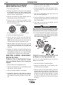
PROCEDURE FOR CHANGING
DRIVE AND IDLE ROLL SETS
5. Rotate the spindle and adapter so the retaining
spring is at the 12 o'clock position.
1. Turn off the power source.
6. Position the Readi-Reel so that it will rotate in a direction when feeding so as to be de-reeled from top the
of the coil.
2. Release the pressure on the idle roll by swinging
the adjustable pressure arm down toward the back
of the machine. Lift the cast idle roll assembly and
allow it to sit in an upright position.
3. Remove the outside wire guide retaining plate by
loosening the two large knurled screws.
4. Twist the drive roll retaining mechanism to the
unlocked position as shown below and remove the
drive roll. (See Figure B.3)
FIGURE B.3
7. Set one of the Readi-Reel inside cage wires on the
slot in the retaining spring tab.
8. Lower the Readi-Reel to depress the retaining spring
and align the other inside cage wires with the grooves
in the molded adapter.
9. Slide cage all the way onto the adapter until the
retaining spring "pops up" fully.
CAUTION
UNLOCKED POSITION
LOCKED POSITION
5. Remove the inside wire guide plate.
6. Replace the drive and idle rolls and inside wire
guide with a set marked for the new wire size.
NOTE: Be sure that the gun liner and contact tip
are also sized to match the selected wire size.
Check to be sure the retaining ring has fully returned to the locking
position and has securely locked the Readi-Reel cage in place.
Retaining spring must rest on the cage, not the welding electrode.
----------------------------------------------------------------------------------------------10. To remove Readi-Reel from Adapter, depress retaining spring tab with thumb while pulling the ReadiReel cage from the molded adapter with both hands.
Do not remove adapter from spindle.
FIGURE B.4
7. Manually feed the wire from the wire reel, over the
drive roll groove and through the wire guide and
then into the brass bushing of the gun and cable
assembly.
8. Replace the outside wire guide retaining plate by
tightening the two large knurled screws. Reposition
the adjustable pressure arm to its original position
to apply pressure. Adjust pressure as necessary.
WIRE REEL LOADING - READI-REELS,
SPOOLS OR COILS
TO MOUNT 10 to 44 Lb. (4.5-20 kg) SPOOLS (12"/300
mm Diameter) or 14Lb.(6 Kg) Innershield Coils:
To Mount a 30 Lb. (14 kg) Readi-Reel Package
(Using the Molded Plastic K363-P Readi-Reel
Adapter):
(For 13-14 lb. (6 Kg) Innershield coils, a K435 Coil
Adapter must be used).
1. Open the Wire Drive Compartment Door
2. Depress the Release Bar on the Retaining Collar
and remove it from the spindle.
3. Place the Optional Adapter on the spindle
4. Re-install the Retaining Collar. Make sure that the
Release Bar “pops up” and that the collar retainers
fully engage the retaining ring groove on the spindle.
1. Open the Wire Drive Compartment Door
2. Depress the Release Bar on the Retaining Collar
and remove it from the spindle.
3. Place the spool on the spindle making certain the
spindle brake pin enters one of the holes in the
back side of the spool (Note: an arrow mark on the
spindle lines up with the brake holding pin to assist
in lining up a hole). Be certain the wire comes off
the reel in a direction so as to de-reel from the top
of the coil.
POWER MIG 300
B-9
OPERATION
4. Re-install the Retaining Collar. Make sure that the
Release Bar “pops up” and that the collar retainers
fully engage the retaining ring groove on the spindle.
B-9
1. Press end of gun against a solid object that is electrically isolated from the welder output and press
the gun trigger for several seconds.
2. If the wire “birdnests”, jams or breaks at the drive
roll, the idle roll pressure is too great. Back the
adjustment knob out 1/2 turn, run new wire through
gun, and repeat above steps.
FEEDING WIRE ELECTRODE
WARNING
When triggered, the electrode and drive mechanism are electrically “hot” relative to work and
ground and remain “hot” several seconds after
the gun trigger is released.
-----------------------------------------------------------------------NOTE: Check that drive rolls, guide plates and gun
parts are proper for the wire size and type being used.
Refer to Table C.1 in ACCESSORIES section.
1. Turn the Readi-Reel or spool until the free end of
the electrode is accessible.
2. While securely holding the electrode, cut off the
bent end and straighten the first six inches. (If the
electrode is not properly straightened, it may not
feed properly through the wire drive system).
3. Release the pressure on the idle roll by swinging
the adjustable pressure arm down toward the back
of the machine. Lift the cast idle roll assembly and
allow it to sit in an upright position. Leave the outer
wire guide plate installed. Manually feed the wire
through the incoming guide bushing and through
the guide plates (over the drive roll groove). Push a
sufficient wire length to assure that the wire has fed
into the gun and cable assembly without restriction.
Reposition the adjustable pressure arm to its original position to apply pressure to the wire.
4. Press gun trigger to feed the electrode wire through
the gun.
IDLE ROLL PRESSURE SETTING
The idle roll pressure adjustment knob is set at the
factory at the #2 hash mark. This is an approximate
setting. The optimum idle roll pressure varies with
type of wire, wire diameter, surface conditions, lubrication, and hardness. As a general rule, hard wires
may require greater pressure, and soft, or aluminum
wire, may require less pressure than the factory setting. The optimum idle roll setting can be determined
as follows:
3. If the only result was drive roll slippage, loosen the
adjustment knob on the conductor plate and pull
the gun cable forward about 6" (15 cm). There
should be a slight waviness in the expose wire. If
there is not waviness, the pressure is too low.
Tighten the adjustment knob 1/4 turn, reinstall the
gun cable and repeat the above steps.
AVOIDING WIRE FEEDING
PROBLEMS
Wire feeding problems can be avoided by observing
the following gun handling procedures:
a. Do not kink or pull cable around sharp corners.
b. Keep the gun cable as straight as possible when
welding or loading electrode through cable.
c. Do not allow dolly wheels or trucks to run over
cables.
d. Keep cable clean by following maintenance instructions.
e. Use only clean, rust-free electrode. Lincoln electrodes have proper surface lubrication.
f. Replace the contact tip when the arc starts to
become unstable or the contact tip end is fused or
deformed.
g. Keep wire reel spindle brake tension to the minimum required to prevent excess reel over-travel
which may cause wire “loop-offs” from the coil.
h. Use proper drive rolls and wire drive/idle roll pressure for wire size and type being used.
POWER MIG 300
B-10
OPERATION
SPECIAL WELDING PROCESSES
AVAILABLE ON THE POWER MIG 300
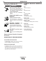
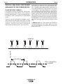
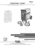
PULSE WELDING (GMAW-P)
The pulsed-arc process is, by definition, a spray transfer process wherein spray transfer occurs in pulses at
regularly spaced intervals. In the time between pulses,
the welding current is reduced and no metal transfer
occurs.
Pulsed-arc transfer is obtained by operating a power
source between low and high current levels. The high
current level or “pulse” forces an electrode drop to the
workpiece. The low current level or “background”
maintains the arc between pulses. (See Figure B.5).
B-10
Pulsed MIG is an advanced form of welding that takes
the best of all the other forms of transfer while minimizing or eliminating their disadvantages. Unlike short circuit, pulsed MIG does not create spatter or run the risk
of cold lapping. The welding positions in pulsed MIG
are not limited as they are with globular or spray and its
wire use is definitely more efficient. Unlike the spray arc
process, pulsing offers controlled heat input that allows
better welding on thin materials, lower wire feed speeds
and leads to less distortion and improved overall quality
and appearance. This is especially important with stainless, nickel and other alloys that are sensitive to heat
input.
In GMAW-P mode, arc control adjusts the background
current and frequency of the wave. When arc control
goes up, the frequency increases thus increasing the
droplet transfer rate.
FIGURE B.5
PEAK AMPS
EACH PULSE DELIVERS ONE DROPLET OF WELD MATERIAL
FREQUENCY
SPRAY TRANSITION
CURRENT
POWER MIG 300
B-11
B-11
OPERATION
When Arc Control is used in the Pulse on Pulse
modes, it does the same things it does in the other
pulsed modes: decreasing the Arc Control decreases
the droplet transfer and weld deposition rate.
Increasing the Arc Control increases the droplet transfer and weld deposition rate. Since Arc Control varies
weld droplet transfer rate, the Arc Control can be used
to vary the ripple spacing in the weld bead.
PULSE-ON-PULSE™ (GMAW-PP)
Pulse on Pulse™ is a Lincoln process specifically
designed for use in welding relatively thin (less than
1/4" thick) aluminum (See Table B.3). It gives weld
beads with very consistent uniform ripple.
In Pulse on Pulse modes, two distinct pulse types are
used, instead of the single pulse type normally used in
GMAW-P. A number of high energy pulses are used
to obtain spray transfer and transfer metal across the
arc. Such pulses are shown in Figure B.6. After a
number "N" of such pulses, depending on the wire
feed speed used, an identical number "N" of low energy pulses are performed. These low energy pulses,
shown in Figure B.6, do not transfer any filler metal
across the arc and help to cool the arc and keep the
heat input low.
BENEFITS OF PULSE ON PULSE FROM
LINCOLN ELECTRIC
• Excellent appearance of the weld bead
• Improved cleaning action
• Reduced porosity
FIGURE B.6
"N" PULSES
Table B.3 shows WFS and Trim settings for common
aluminum types and wire sizes when welding with
Pulse-on-Pulse. The welds made to obtain the values
in the table were fillet welds in the flat position. The
values in the table can be helpful as a starting point to
establish a welding procedure. From there, adjustments need to be made to set the proper procedure
for each specific application (out-of-position, other
types of joints, etc.).
"N" PULSES
HIGH HEAT
PULSES
LOW HEAT
PULSES
PEAK
AMPS
BACKGROUND
AMPS
TIME
The Peak Current, Background Current, and
Frequency are identical for the high energy and low
energy pulses. In addition to cooling the weld down,
the major effect of the low energy pulses is that they
form a weld ripple. Since they occur at very regular
time intervals, the weld bead obtained is very uniform
with a very consistent ripple pattern. In fact, the bead
has its best appearance if no oscillation of the welding
gun ("whipping") is used.(See Figure B.7)
The comments on Table B.3 show values of WFS
below which it is not recommended to weld. The reason is, that below these values the weld transfer will
change from a spray arc to a short-arc, which is not
advisable when welding aluminum.
FIGURE B.7
WELDING PROCEDURES FOR PULSE-ON-PULSE (TABLE B.3)
Aluminum 4043
Aluminum 5356
Aluminum 5356
100% Ar.
100% Ar.
100% Ar.
100% Ar.
WIRE
E4043
E4043
E5356
E5356
WIRE SIZE
0.035
3/64
0.035
3/64
WELD MODE
98
99
101
102
250 / 1.0
200 / 1.0
230 / 1.0
225 / 1.0
10 ga.
400 /1.0
280 / 1.0
425 / 1.0
400 / 1.0
3/16
550 / 1.0
340 / 1.0
670 / 1.0
500 / 1.0
1/4
600 / 1.0
400 / 1.0
700 / 1.0
550 / 0.9
Not Recommended
below 200 WFS
Not Recommended
below 100 WFS
Not Recommended
below 200 WFS
Not Recommended
below 200 WFS
WFS / TRIM
Aluminum 4043
GAS
MATERIAL
THICKNESS
MATERIAL
14 ga.
COMMENTS
POWER MIG 300
B-12
B-12
OPERATION
POWER MODE™
Start by setting the wire feed speed based upon material thickness and appropriate travel speed. Then
adjust the Volts/Trim knob as follows:
The Power Mode™ process was developed by
Lincoln to maintain a stable and smooth arc at low
procedure settings which are needed to weld thin
metal without pop-outs or burning-through. For
Aluminum welding, it provides excellent control and
the ability to maintain constant arc length. This results
in improved welding performance in two primary types
of applications.
• For steel, listen for the traditional “frying egg”
sound of a good short-arc MIG procedure to know
you have the process set correctly.
• For aluminum, simply adjust the Volts/Trim knob
until the desired arc length is obtained.
• Short Arc MIG at low procedure settings.
Note the Volts/Trim display is simply a relative number
and DOES NOT correspond to voltage.
• Aluminum MIG welding.
Power Mode™ is a method of high speed regulation
of the output power whenever an arc is established. It
provides a fast response to changes in the arc. The
higher the Power Mode Setting, the longer the arc. If a
welding procedure is not established, the best way to
determine the Power Mode Setting is by experimentation until the desired output result is established.
Some procedure recommendations appear in Table
B.4.
In the Power Mode two variables need to be set:
• Wire Feed Speed
• Power Mode Trim
Setting up a Power Mode procedure is similar to setting a CV MIG procedure. Select a shielding gas
appropriate for a short arc process.
• For steel, use 75/25 Ar/CO2 shield gas.
• For Stainless, select a Helium blend Tri-Mix.
• For Aluminum, use 100% Ar.
Recommended Welding Procedures for Power Mode - Table B.4
Aluminum 4043 Aluminum 5356
Mild Steel
Mild Steel
Mild Steel
Mild Steel
Mild Steel
Mild Steel
Stainless Steel Stainless Steel
WIRE
E4043
E5356
L56
L56
L56
L56
L56
L56
E308L
WIRE SIZE
0.035
0.035
0.025
0.025
0.030
0.030
0.035
0.035
0.030
0.035
GAS
100% Ar.
100% Ar.
100% CO2
75/25 Ar/CO2
100% CO2
75/25 Ar/CO2
100% CO2
75/25 Ar/CO2
Tri-mix
Tri-mix
80 / 1.5
50 / 0.5
110 / 2.0
WFS / POWER MODE SETTING
MATERIAL THICKNESS
MATERIAL
E308L
22 ga.
Not Recommended
100 / 0.8
Not Recommended
90 / 1.0
20 ga.
120 / 1.0
120 / 1.0
100 / 0.7
100 /1.0
18 ga.
140 / 1.7
140 / 1.5
110 / 1.5
110 / 1.5
100 / 2.5
100 / 2.5
110 / 2.0
16 ga.
190 / 2.0
190 / 2.0
125 / 2.0
125 / 2.0
125 / 3.0
125 / 3.0
140 / 2.5
130 / 2.7
260 / 3.0
260 / 3.0
160 / 2.3
160 / 2.3
160 / 3.8
160 / 3.5
210 / 3.0
190 / 3.5
330 / 5.0
330 / 4.5
14 ga.
400 / 2.0
400 / 2.5
230 / 3.5
230 / 3.5
200 / 5.0
200 / 4.5
270 / 5.0
230 / 6.0
10 ga.
500 / 7.0
500 / 7.0
300 / 6.0
300 / 6.0
240 / 6.5
240 / 7.0
325 / 6.5
300 / 7.0
3/16
570 / 9.0
600 / 7.8
400 / 7.5
400 / 7.0
1/4
700 / 9.1
700 / 8.5
12 ga.
COMMENTS
Not
Not
Recommended Recommended
below 400
below 400
WFS
WFS
POWER MIG 300
C-1
DRIVE ROLL KITS
Refer to Table C.1 for various drive roll kits that are
available for the POWER MIG. All items in Bold are
supplied standard with the POWER MIG.
TABLE C.1
Wire
Size
.023”-.030” (0.6-0.8 mm)
.035” (0.9 mm)
.045” (1.2 mm)
.040” (1.0mm)
.035-.045” (0.9-0.2mm)
.035” (0.9 mm)
Cored
.045” (1.2 mm)
Aluminum
3/64” (1.2 mm)
Solid
Steel
C-1
ACCESSORIES
Drive Roll Kit
KP1696-030S
KP1696-035S
KP1696-045S
KP-1696-2
KP-1696-1
KP1697-035C
KP1697-045C
KP1695-3/64A
*.035 Aluminum recommended for Push-Pull systems only.
3/64" (1.2 mm) ALUMINUM
FEEDING KIT (K2153-1)
Length
Part No.
10' (3.0 m)
12' (3.6 m)
15' (4.5 m)
K470-1
K470-7
K470-3
English Wire
Size
Metric Wire
Size
.035 – .045"
0.9 – 1.2 mm
MAGNUM GUN CONNECTION KIT
(Optional K466-6)
Using the optional K466-6 Magnum Connection kit for
the POWER MIG permits use of standard Magnum
200, 300 or 400 gun and cable assemblies.
K1692-2 SPOOL GUN (PRINCETM XL)
When the POWER MIG Gun Selector Switch is in the
“Standard / Spool Gun” position, the POWER MIG provides gun trigger switch transfer between the Magnum
gun or the spool gun for the same polarity welding with
different wire and gas processes.
CAUTION
This kit helps push feeding aluminum through standard machine feeder and gun. It provides gun and
wire drive conversion parts to weld with 3/64" (1.2
mm) aluminum wire. 5356 alloy aluminum wire is recommended for best push feeding performance.
Kit includes drive rolls and wire guide plate for the
wire drive, liner and two contact tips for the gun, along
with installation instructions.
K363P READI-REEL ADAPTER
The K363P Readi-Reel Adapter mounts to the 2"
spindle. It is needed to mount the 22-30 lb. ReadiReels.
DUAL CYLINDER MOUNTING KIT
(K1702-1)
Permits stable side-by-side mounting of two full size
(9" dia. x 5' high) gas cylinders with “no lift” loading.
Simple installation and easy instructions provided.
Includes upper and lower cylinder supports, wheel
axles and mounting hardware.
ALTERNATIVE MAGNUM GMAW
GUN AND CABLE ASSEMBLIES
The following Magnum 300 gun and cable assemblies
are separately available for use with the POWER MIG
300. Each is rated 300 amps 60% duty cycle (or 300
amps 40% duty) and is equipped with the integrated
connector, twist-lock trigger connector, fixed nozzle
and insulator, and includes a liner, diffuser, and contact tips for the wire sizes specified:
Closing either gun trigger will cause the electrode of
both guns to be electrically “HOT”. Be sure unused
gun is positioned so electrode or tip will not contact
metal case or other metal common to work.
----------------------------------------------------------------------Because the control circuitry senses each gun through
its trigger leads, weld parameters are displayed and
adjustable for the last gun that was triggered.
1. Pulling the trigger for the built-in feeder gun
(Magnum 300):
• Disables spool gun operation.
• Changes the displays of the POWER MIG 300 to
correspond to feeder gun operation.
• Closing feeder gun trigger starts feeder gun welding and makes both electrodes electrically “HOT”.
2. Pulling SPOOL GUN Trigger:
• Disables built-in feeder gun operation.
• Changes the displays of the POWER MIG 300 to
correspond to Spool Gun operation.
• Closing spool gun trigger starts spool gun welding
and makes both electrodes electrically “HOT”.
3. Operation with POWER MIG 300:
• Install the spool gun per the installation instructions
• Turn the POWER MIG 300 input power ON.
• Make sure that the Gun Selector Switch is in the
“Standard / Spool Gun” position.
• Pull and release the trigger of the Spool Gun. The
Power Mig recognizes the spool gun as active and weld
parameters are adjustable for welding with the Spool
Gun
POWER MIG 300
C-2
Non-Synergic Weld Modes (Mode 5)
• Voltage is adjustable at the power source. The
right control knob on the power source will
adjust the voltage that is displayed in the meter
directly above it.
•
•
The left Display (WFS / AMPS) on the POWER
MIG 300 will have 4 dashes (----) to indicate
that the left control knob on the power source is
inactive. Wire Feed Speed is set at the Spool
Gun.
The following procedure settings for Aluminum
4043 can be used as initial settings for making
test welds to determine final settings:
Wire Dia.
In. (mm)
WFS Setting
Spool Gun
.030" (.8 mm)
.035" (.9 mm)
3/64" (1.2 mm)
270
250
240
Arc Voltage
Setting
PUSH-PULL FEEDING CONNECTION
ADAPTER KIT (K2154-1)
The push-pull adapter kit provides direct connection of
a Cobra Gold or Prince XL torch to the POWER MIG 300
wire feeder welder.
The kit is intended for use with the following Cobra
Gold or Prince XL torches:
Air Cooled 15’(5m) K1589-1 Water-Cooled 15’(5m) K1590-1
Air Cooled 25’(8m) K1589-2 Water-Cooled 25’(8m) K1590-2
Air Cooled 50’(15m) K1589-3 Water-Cooled 50’(15m) K1590-3
Prince XL
The POWER MIG 300 is designed to enable synergic
weld modes and synergic pulse processes with the
spool gun. The actual wire feed speed (WFS) of the
spool gun must be measured and manually set on the
POWER MIG 300 as a work point for the POWER
MIG 300 (SPD).
• In synergic modes when the spool gun trigger is
pulled, an adjustable value for the SPD work
point is displayed in the left meter. The letters
SPD are displayed in the right meter.
The left control knob adjusts the SPD value.
The right control knob is inactive.
Measure the actual WFS, in inches per minute,
at the spool gun and set the SPD at the
POWER MIG 300 to match this value. WFS can
be measured by pulling the trigger of the spool
gun and feeding wire for 6 seconds. Measure
the length of wire (in inches) that was fed and
multiply by 10.
• The POWER MIG 300 is now configured and
ready to weld in the synergic mode.
• Adjustment of the SPD value from the set value
has the affect of adjusting trim or arc length.
• To increase the arc length; increase the SPD
value at the POWER MIG 300 to a value higher
than the actual WFS.
Remember; do not change the WFS at the spool
gun.
• To decrease the arc length; decrease the SPD
value at the POWER MIG 300 to a value lower
than the actual WFS.
•
Remember: The dialed in SPD value at the POWER
MIG 300 does not control the WFS at the spool gun.
Rather, it is adjusting the POWER MIG 300 synergic
work point. Therefore, adjusting the SPD value will
not change your actual WFS at the spool gun.
WFS can only be changed at the spool gun.
Cobra Gold
15V
16V
20V
4. Synergic Weld Modes
•
C-2
ACCESSORIES
Air Cooled 15’(5m) K1591-1 Water-Cooled 15’(5m) K1592-1
Air Cooled 25’(8m) K1591-2 Water-Cooled 25’(8m) K1592-2
Air Cooled 50’(15m) K1591-3 Water-Cooled 50’(15m) K1592-3
CAUTION
Remove all input power to the POWER MIG 300
before installing the Connection Adapter Kit.
------------------------------------------------------------------------
WARNING
Refer to the Owner’s Manual of the Torch for
Amperage and Duty Cycle rating information. The
torch rating may not match the rating of the power
source.
------------------------------------------------------------------------
MAKING A WELD WITH THE PRINCE XL
OR COBRA GOLD TORCH INSTALLED
• Set the idle roll pressure on the wire drive between
an indicator reading of 0-2. A recommended start
point is 1.5.
• Set the Gun Selection toggle switch located inside
the wire drive compartment directly above the pushpull control cable connector to "PUSH-PULL GUN."
• Depending on the weld mode, set the Voltage or
Trim at the POWER MIG 300 using the right control
knob located on the upper case front panel.
• The Wire Feed Speed (WFS) is set using the control
knob on the Torch. The left control knob on the
POWER MIG 300 is inactive. The actual WFS being set
at the torch is displayed on the POWER MIG 300.
• All weld parameters normally available for the active
weld mode are available during push-pull operation.
Refer to the Operation Section of this manual.
POWER MIG 300
D-1
MAINTENANCE
SAFETY PRECAUTIONS
D-1
CONTACT TIP AND GAS NOZZLE
INSTALLATION
WARNING
ELECTRIC SHOCK can kill.
• Have an electrician install and
service this equipment.
• Turn the input power off at the
fuse box before working on
equipment
• Do not touch electrically hot
parts.
GENERAL MAINTENANCE
In extremely dusty locations, dirt may clog the air passages causing the welder to run hot. Blow dirt out of
the welder with low-pressure air at regular intervals to
eliminate excessive dirt and dust build-up on internal
parts.
The fan motors have sealed ball bearings which
require no service.
DRIVE ROLLS AND GUIDE PLATES
After every coil of wire, inspect the wire drive mechanism. Clean it as necessary by blowing with low pressure compressed air. Do not use solvents for cleaning
the idle roll because it may wash the lubricant out of
the bearing. All drive rolls are stamped with the wire
sizes they will feed. If a wire size other than that
stamped on the roll is used, the drive roll must be
changed.
For instructions on replacing or changing drive roll,
see “Wire Drive Rolls” in Operation section.
a. Choose the correct size contact tip for the electrode being used (wire size is stenciled on the side
of the contact tip) and screw it snugly into the gas
diffuser.
b. Be sure the nozzle insulator is fully screwed onto
the gun tube and does not block the gas holes in
the diffuser. (NOTE: Insulator is not required when
using the optional fixed gas nozzles.)
c. Slip the appropriate gas nozzle onto the nozzle
insulator. Adjustable gas nozzles are available with
a .62” (15.9 mm) or .50” (12.7 mm) I.D., and in both
standard (flush) and recessed design. The proper
nozzle should be selected based on the welding
application. Different length fixed nozzles are also
available to fit 300 and 400 amp gun tubes to allow
either spray or short-circuiting transfer welding.
Choose the gas nozzle as appropriate for the
GMAW process to be used. Typically, the contact
tip end should be flush to .12” (3.1 mm) extended
for the short-circuiting transfer process and .12”
(3.1 mm) recessed for spray transfer. For the
Outershield (FCAW) process, 1/8” (3 mm) recess is
recommended.
GUN TUBES AND NOZZLES
a. Replace worn contact tips as required.
b. Remove spatter from inside of gas nozzle and from
tip after each 10 minutes of arc time or as required.
GUN CABLE CLEANING
To help prevent feeding problems, clean cable liner
after using approximately 300 pounds (136 kg) of
electrode. Remove the cable from the wire feeder and
lay it out straight on the floor. Remove the contact tip
from the gun. Using an air hose and only partial pressure, gently blow out the cable liner from the gas diffuser end.
POWER MIG 300
D-2
D-2
MAINTENANCE
CAUTION
Excessive pressure at the start may cause the dirt
to form a plug.
Flex the cable over its entire length and again blow
out the cable. Repeat this procedure until no further
dirt comes out. If this has been done and feed problems are experienced, try liner replacement, and refer
to trouble shooting section on rough wire feeding.
5. Seat Liner bushing into back of gun. Secure Liner
by tightening set screw. Do not install the gas diffuser at this time.
6. Lay the cable straight and trim Liner to 9/16”.
Remove burrs.
7. Secure the gas diffuser into the tube.
8. Tighten the set screw against the Liner.
CAUTION
LINER REMOVAL AND REPLACEMENT
(SEE FIGURE D.1)
LINER REMOVAL, INSTALLATION AND TRIMMING
INSTRUCTIONS FOR MAGNUM 300
NOTE: The variation in cable lengths prevents the
interchangeability of liners between guns. Once a liner
has been cut for a particular gun, it should not be
installed in another gun unless it can meet the liner
cutoff length requirement. Liners are shipped with the
jacket of the liner extended the proper amount.
This screw should only be gently tightened. Over
tightening will split or collapse the liner and cause
poor wire feeding.
------------------------------------------------------------------------
1. Remove the gas nozzle.
2. Remove the gas diffuser from the gun tube. If gas
diffuser contains a small set screw, loosen the set
screw.
3. Lay gun and cable out straight on a flat surface.
Loosen set screw of the connector on the back end
of the gun.
4. Insert the untrimmed Liner into the back end of the
gun.
FIGURE D.1
INSULATION TUBE
FEEDR END
CABLE HANDLE
GUN HANDLE
GUN TUBE
BRASS CABLE
CONNECTOR
MOLDED GAS PLUG
SET SCREW
SET SCREW
CLAMPING SCREW
GAS DIFFUSER
LINER ASSEMBLY (LINER BUSHING TO BE SEATED
TIGHT AGIANST BRASS CABLE CONNECTOR)
NOZZLE INSULATION
GAS NOZZLE
POWER MIG 300
9/16 (14.3mm)
LINER TRIM
LENGTH
E-1
TROUBLESHOOTING
E-1
WARNING
Service and Repair should only be performed by Lincoln Electric Factory Trained Personnel.
Unauthorized repairs performed on this equipment may result in danger to the technician and
machine operator and will invalidate your factory warranty. For your safety and to avoid Electrical
Shock, please observe all safety notes and precautions detailed throughout this manual.
__________________________________________________________________________
This Troubleshooting Guide is provided to help you
locate and repair possible machine malfunctions.
Simply follow the three-step procedure listed below.
Step 1. LOCATE PROBLEM (SYMPTOM).
Look under the column labeled “PROBLEM (SYMPTOMS)”. This column describes possible symptoms
that the machine may exhibit. Find the listing that
best describes the symptom that the machine is
exhibiting.
Step 3. RECOMMENDED COURSE OF ACTION
This column provides a course of action for the
Possible Cause, generally it states to contact your
local Lincoln Authorized Field Service Facility.
If you do not understand or are unable to perform the
Recommended Course of Action safely, contact your
local Lincoln Authorized Field Service Facility.
Step 2. POSSIBLE CAUSE.
The second column labeled “POSSIBLE CAUSE” lists
the obvious external possibilities that may contribute
to the machine symptom.
CAUTION
If for any reason you do not understand the test procedures or are unable to perform the tests/repairs safely, contact your
Local Lincoln Authorized Field Service Facility for technical troubleshooting assistance before you proceed.
POWER MIG 300
E-2
E-2
TROUBLESHOOTING
Observe all Safety Guidelines detailed throughout this manual
PROBLEMS
(SYMPTOMS)
POSSIBLE AREAS OF
MISADJUSTMENT(S)
RECOMMENDED
COURSE OF ACTION
Major physical or electrical damage 1. Contact your local authorized
Lincoln Electric Field Service
is evident when the sheet metal
facility for technical assistance.
covers are removed.
Input fuses keep blowing, or input 1. Make certain that the fuses or
breakers are properly sized. See
breaker keeps tripping
installation section of the manual
for recommended fuse and
breaker sizes.
2. Welding procedure is drawing too
much output current, or duty
cycle is too high. Reduce output
current, duty cycle or both.
3. There is internal damage to the
power source. Contact an authorized Lincoln Electric Service
facility.
Machine will not power up (No lights) 1. Make certain that the power
switch is in the "ON" position.
2. Input voltage selection made
improperly. Power down, check
input voltage reconnect according to diagram on reconnect
cover.
If all recommended possible areas
of misadjustment have been
checked and the problem persists,
Contact your local Lincoln
Authorized Field Service Facility.
Machine won’t weld, can’t get any 1. If the displays show an Err ###
output.
see the fault section for corrective action.
2. If the displays are not lit refer to
machine will not power up section.
3. If the thermal symbol is lit refer to
the thermal section.
Thermal symbol is lit
1. Check for proper fan operation
2. Check for material blocking
intake or exhaust louvers.
CAUTION
If for any reason you do not understand the test procedures or are unable to perform the tests/repairs safely, contact your
Local Lincoln Authorized Field Service Facility for technical troubleshooting assistance before you proceed.
POWER MIG 300
E-3
E-3
TROUBLESHOOTING
Observe Safety Guideline detailed in the beginning of this manual.
PROBLEMS
(SYMPTOMS)
POSSIBLE AREAS OF
MISADJUSTMENT(S)
RECOMMENDED
COURSE OF ACTION
OUTPUT PROBLEMS
Output voltage and wire feed is present when gun trigger is not pulled
(not activated).
1. Check Weld Mode to make sure
the unit is in a CV Mode And not
a CC Mode.
2. Remove gun assembly from
machine. If problem is solved
gun assembly is faulty. Repair or
replace.
3. If problem persists when gun
assembly is removed from
machine then the problem is
within the POWER MIG 300.
Machine output is low. Welds are
“cold”, weld bead is rounded or
bumped up demonstrating poor wetting into plate.
1. Check input voltage. Make sure
input voltage matches nameplate rating and reconnect panel
configuration.
2. Make sure settings for wire feed
speed and voltage are correct
for process being used.
3. Make sure output polarity is correct for process being used.
4. Check welding cables and gun
assembly for loose or faulty connections.
Poor arc striking with electrode
sticking or blasting off.
If all recommended possible areas
of misadjustment have been
checked and the problem persists,
Contact your local Lincoln
Authorized Field Service Facility.
1. Make sure settings for wire feed
speed and voltage are correct
for process being used.
2. The Run-In (Fast or Slow) speed
may be wrong for process and
technique being used. See
Operation Section.
3. The gas shielding may be
improper for process being used.
CAUTION
If for any reason you do not understand the test procedures or are unable to perform the tests/repairs safely, contact your
LOCAL AUTHORIZED LINCOLN ELECTRIC FIELD SERVICE FACILITY for assistance before you proceed.
POWER MIG 300
E-4
TROUBLESHOOTING
E-4
Observe Safety Guidelines detailed in the beginning of this manual.
PROBLEMS
(SYMPTOMS)
POSSIBLE AREAS OF
MISADJUSTMENT(S)
RECOMMENDED
COURSE OF ACTION
FEEDING PROBLEMS
Rough wire feeding or wire will not
feed but drive rolls are turning.
The wire feed stops while welding.
When trigger is released and pulled
again the wire feed starts.
1. The gun cable may be kinked or twisted.
2. The wire may be jammed in the gun
cable, or gun cable may be dirty.
3. Check drive roll tension and
position of grooves.
4. Check for worn or loose drive rolls.
5. The electrode may be rusty or dirty.
6. Check for damaged or incorrect
contact tip.
7. Check wire spindle for ease of
rotation and adjust break tension knob if necessary.
1. Check the wire feed drive rolls
and motor for smooth operation.
2. Check for restrictions in the wire
feed path. Check the gun and
cable for restrictions.
3. Make sure gun liner and tip are
correct for wire size being used.
4. Make sure drive rolls and guide plates
are clean and are the correct size.
If all recommended possible areas
of misadjustment have been
checked and the problem persists,
Contact your local Lincoln
Authorized Field Service Facility.
5. Check spindle for ease of rotation.
CAUTION
If for any reason you do not understand the test procedures or are unable to perform the tests/repairs safely, contact your
LOCAL AUTHORIZED LINCOLN ELECTRIC FIELD SERVICE FACILITY for assistance before you proceed.
POWER MIG 300
E-5
E-5
TROUBLESHOOTING
Observe Safety Guidelines detailed in the beginning of this manual.
PROBLEMS
(SYMPTOMS)
POSSIBLE AREAS OF
MISADJUSTMENT(S)
RECOMMENDED
COURSE OF ACTION
GAS FLOW PROBLEMS
Gas does not flow when gun trigger
is pulled.
1. Make sure gas supply is connected properly and turned “on”.
2. If the gas solenoid does actuate
(click) when the gun trigger is
pulled there may be a restriction
in the gas supply line.
3. The gun cable assembly may be
faulty. Check or replace.
If all recommended possible areas
of misadjustment have been
checked and the problem persists,
Contact your local Lincoln
Authorized Field Service Facility.
4. If gas solenoid does not operate
when gun trigger is pulled the
problem is within the POWER
MIG 300.
5. Make sure the gun is pushed all
the way into gun mount and is
properly seated.
CAUTION
If for any reason you do not understand the test procedures or are unable to perform the tests/repairs safely, contact your
LOCAL AUTHORIZED LINCOLN ELECTRIC FIELD SERVICE FACILITY for assistance before you proceed.
POWER MIG 300
E-6
E-6
TROUBLESHOOTING
Observe all Safety Guidelines detailed throughout this manual
Fault Codes
Code
39
44
47
81
82
Description
Glitch on the primary over
current fault interrupt; possibly
caused by noise or a signal level
(misc. hardware fault #1)
Main CPU problem. The DSP
has detected a problem with the CPU.
Glitch on the CAP/heart beat
interrupt; possibly caused by
noise or a signal level right at
the trip threshold.
(misc. hardware fault #2)
Motor overload-average motor
current exceeded 8.00 amps for
more than 0.50 seconds
Motor overcurrent-average motor
current exceeded 3.50 amps for
more than 10.0 seconds
Misadjustment(s)
Check the machine ground.
If problem persists contact an
authorized Lincoln Field Service
Shop.
Check the machine ground.
Corrective Action
Self-clearing as
condition ceases.
If problem persists contact an
authorized Shop.
Verify motor armature is not
binding. Verify Wire Spool
is not binding.
Verify wire can move freely in
cable. Verify Spool Brake is not
set to tight.
Displays
Description
Scrolling dash
Appears at power up while the machine is going through its self configuration
"Err" "####"
Fault code display. The first fault to occur will be displayed for three
seconds. The display will cycle through fault codes for all faults that
persist after the initial three-second period are displayed for 1 second each.
"----" "----"
Weld mode is changing
"####" "####"(on steady) Machine output is on. Left display is current, right display is voltage.
If actively welding, the displays are arc current and arc voltage. If
not actively welding, the display will show work point.
"####" "####" (blinking)
Weld just finished – the average arc voltage and current will be
blinked for 5 seconds following a weld. If the work point changes
during this 5 second period, the display will revert to the above
mode.
CAUTION
If for any reason you do not understand the test procedures or are unable to perform the tests/repairs safely, contact your
Local Lincoln Authorized Field Service Facility for technical troubleshooting assistance before you proceed.
POWER MIG 300
E-7
E-7
TROUBLESHOOTING
Observe all Safety Guidelines detailed throughout this manual
PROBLEMS
(SYMPTOMS)
POSSIBLE AREAS OF
MISADJUSTMENT(S)
RECOMMENDED
COURSE OF ACTION
PUSH PULL WIRE FEEDING PROBLEMS
While loading wire, the rear drive
rolls stop while pushing wire
through the torch.
1. Check torch cable for kinks.
Torch cable should be laid out
relatively straight.
2. Check to see that the spindle
brake is not set too tight. There
should be an aluminum spacer
behind the spindle brake. Refer
to the push-pull connection kit for
this spacer.
3. Check the wire at the spool.
Make sure wire is not crossed
and is de-reeling properly.
4. Increase wire feed speed to 350400 ipm.
If all recommended possible areas
of misadjustment have been
checked and the problem persists,
Contact your local Lincoln
Authorized Field Service Facility.
5. If problem continues after a thru
d are checked then the Stall
Factor Number needs to be
increased. (See: Stall Factor
Number Adjustment)
While loading wire, the wire bird
nests before the wire gets all the
way through the torch.
1. Check torch cable for kinks.
Torch cable should be laid out
relatively straight.
2. Make sure liner conduit is inserted all the way into the rear wire
drive so that it is up against the
inner black plastic wire guide.
3. Inner black plastic wire guide is
worn out. Replace guide.
4. Slow down wire feed speed while
pushing wire up through the
liner. Recommended setting =
350 ipm.
5. Clean or replace contact tip.
CAUTION
If for any reason you do not understand the test procedures or are unable to perform the tests/repairs safely, contact your
Local Lincoln Authorized Field Service Facility for technical troubleshooting assistance before you proceed.
POWER MIG 300
E-8
E-8
TROUBLESHOOTING
Observe all Safety Guidelines detailed throughout this manual
PROBLEMS
(SYMPTOMS)
POSSIBLE AREAS OF
MISADJUSTMENT(S)
RECOMMENDED
COURSE OF ACTION
PUSH PULL WIRE FEEDING PROBLEMS
While loading wire the wire bird
nests if the wire misses the outlet
guide while shooting the gap in the
torch.
1. Straighten the first six inches of
the wire before feeding it into the
rear wire drive.
2. Make sure the torch drive rolls
are tightened slightly to help the
wire jump the gap.
3. Slow down wire feed speed while
pushing wire through torch liner.
Recommend setting = 350 ipm.
4. If problem continues after a thru
c are checked then the Stall
Factor Number needs to be
decreased. (See: Stall Factor
Number Adjustment)
Arc length varies while welding (arc
length is not constant).
If all recommended possible areas
of misadjustment have been
checked and the problem persists,
Contact your local Lincoln
Authorized Field Service Facility.
1. PM 300 drive rolls set too tight.
The tension arm should be set at
1 to 1-1/2.
2. Check to see that the spindle
brake is not set too tight. There
should be an aluminum spacer
behind the spindle brake. Refer
to the push-pull connection kit for
this spacer.
3. Clean or replace contact tip.
4. If problem continues after a and
c are checked then the Stall
Factor Number needs to be
increased. (See Stall Factor
Number Adjustment)
CAUTION
If for any reason you do not understand the test procedures or are unable to perform the tests/repairs safely, contact your
Local Lincoln Authorized Field Service Facility for technical troubleshooting assistance before you proceed.
POWER MIG 300
E-9
E-9
TROUBLESHOOTING
Observe all Safety Guidelines detailed throughout this manual
PROBLEMS
(SYMPTOMS)
POSSIBLE AREAS OF
MISADJUSTMENT(S)
RECOMMENDED
COURSE OF ACTION
PUSH PULL WIRE FEEDING PROBLEMS
During Welding the wire continues
to burn back to the tip.
1. Check to see that the spindle
brake is not set too tight. There
should be an aluminum spacer
behind the spindle brake. Refer
to the push-pull connection kit for
this spacer.
2. POWER MIG 300 drive rolls set too
tight. The tension arm should be
set at 1 to 1-1/2.
3. Push-Pull torch drive rolls set too
tight. Refer to owners manual for
proper setting.
4. If pulse welding the trim value
may be set too high.
If all recommended possible areas
of misadjustment have been
checked and the problem persists,
Contact your local Lincoln
Authorized Field Service Facility.
5. Clean or replace contact tip.
6. If problem continues after a thru
e are checked then the Stall
Factor Number needs to be
increased. (See Stall Factor
Number Adjustment)
Wire bird nests while welding.
1. Torch liner conduit not inserted
all the way so that it is touching
the inner black plastic wire guide.
2. Inner black plastic wire guide is
worn out. Replace guide.
3. Push-Pull torch drive rolls set too
tight. Refer to owners manual for
proper setting.
4. If problem continues after a thru
c are checked then lower your
Stall Factor Number. (See: Stall
Factor Number Adjustment)
CAUTION
If for any reason you do not understand the test procedures or are unable to perform the tests/repairs safely, contact your
Local Lincoln Authorized Field Service Facility for technical troubleshooting assistance before you proceed.
POWER MIG 300
E-10
TROUBLESHOOTING
E-10
Observe all Safety Guidelines detailed throughout this manual
PUSH PULL WIRE FEEDING PROBLEMS
STALL FACTOR - an adjustment on the POWER MIG 300 that allows the welder to adjust the maximum amount of
power going to the rear drive motor. The purpose is to send only enough power to the rear drive motor to pull the
wire off the spool and get the wire up the torch liner.
STALL FACTOR NUMBER ADJUSTMENT
1. Turn the POWER MIG 300 off.
2. Hold the Push-Pull Torch trigger in and turn the power back on. Continue to hold the trigger in while machine
powers up.
3. Once the machine displays "SF" in the left display and a number 5 to 35 in the right display the trigger can be
released.
4. Use the volts / trim knob to adjust the Stall Factor Number.
5. Once the Stall Factor Number is adjusted push the select switch up.
6. The display should scroll the word “SAVEd” if the number was changed. The display will scroll "no CHANGE" if
the SF number was not changed.
7. The machine should automatically switch back to normal operation after it is done saving the SF number.
CAUTION
If for any reason you do not understand the test procedures or are unable to perform the tests/repairs safely, contact your
Local Lincoln Authorized Field Service Facility for technical troubleshooting assistance before you proceed.
POWER MIG 300
1
2
3
4
5
6
7
8
9
10
J341
J34
6
6
3
14
7
3
1
6
12
7
2
1
9 PIN
P50
123
456
789
H1
L1
SELECT
SWITCH
3417
3411A
3416
L2
H4
76
75
SPOOL GUN/ D E F
G
PUSH-PULL
A
C
AMPHENOL
B
(VIEWED
FROM
REAR)
E D
FOOT
C
AMPTROL F
AMPHENOL A B
H4
LINE
SWITCH
L2
H1
H1
H1
L1
CONTROL
RECTIFIER
3214
-
4
X2
X4
X1
502
115V
FAN
MOTOR
TO +
STUD
FAN
L2
L9
L3
2520
2
77A
4A
2A
75A
3218
3214
76A
GND
4A
4
2
2A
75
75A
76
76A
77
77A
3218
L5
3234
3233
503A
831:B
3244
3243
834
GAS
SOLENOID
833
832:W
GEARBOX
WIRE
DRIVE
MOTOR
2530
77
X6
X5
X3
X6
X5
472
3234
H4
L4
+
472B
H3
H5
H2
H1
471B
R1
SPI SPOOL GUN BOARD
715
716
472
437
471
SHIELDED CABLE
1101 3244
1102 3243
431
C2
C1
B2
B3
J99
B1
412
411
B6
LEM
C4
802
804
801
806
1 2 3 4
B5
410
C3
407
B4
408
841:R
844:B
TACH
847:U
L8
431
B6
851
852
1 2 3
B2
503A
855
SPOOL GUN/
PUSH-PULL
SWITCH
4
J361
ENCODER
P.C. BOARD
401
L7
L6
J36
J37
-STUD
8512
LOCATED ON
CASE FRONT
FLEX
FEEDER BOARD
903
S3 RS232
CONNECTOR
1
2
3
4
5
6
7
20
TP6
TP5
901
TP4
FLEX
903B
R2
901B
L1
CHOKE +STUD
405
1103
DISPLAY
P.C. BOARD
1104 437
406 402
503
403
GUN TRIGGER
SHIELDED
CABLE
300A CHOPPER BOARD
DIODE
BRIDGE
B5
B1
832:W 834 836
831:B 833 835
C5
2400/100
FAN +
~ RELAY -
DIGITAL POWER SUPPLY BOARD
806
804
801
802
715
716
615
604
611
607
604
502
503
410
411
412
405
406
407
408
401
402
403
SHIELDED
CABLE
251
253
254
1
2
3
4
5
6
7
8
1
2
3
4
5
6
7
8
9
10
11
12
13
14
15
16
1
2
3
4
5
6
7
8
9
10
11
12
13
14
15
16
1
2
3
4
1
2
3
4
5
6
7
8
9
10
11
12
1
2
3
4
5
6
7
8
9
10
J8
J7
J6
J5
J4
J3
254
253
251
B
O
A
R
D
C
O
N
T
R
O
L
901
903
12-21-2001A
G3852
1102 1104
1101 1103
ENHANCED DIAGRAM
NOTE: This diagram is for reference only. It may not be accurate for all machines covered by this manual. The specific diagram for a particular code is pasted inside
the machine on one of the enclosure panels. If the diagram is illegible, write to the Service Department for a replacement. Give the equipment code number..
9 PIN
J50
3 2 1
6 5 4
9 8 7
(VIEWEDFROM LEAD SIDE OF RECEPTACLE)
PANEL RECEPTACLE CAVITY NUMBERING SEQUENCE
ALL CASE FRONT COMPONENTS SHOWN VIEWED FROM REAR.
L2 THRU L9 ARE RF CHOKES
SET
SWITCH
3415
3411A
3411
3414
SHIELDED CABLE
W
B
G
RECONNECT PANEL
H5 H2 H3 H4
1
4
2
FLEX
3414
3415
3416
3417
CONNECTOR CAVITY NUMBERING SEQUENCE
(VIEWED FROM COMPONENT SIDE OF BOARD)
16
9
4
5
1
8
1
8
10
6
1
4
1
5
LEAD COLOR CODE:
B=BLACK OR GRAY
R=RED OR PINK
W=WHITE
G=GREEN (W/YELLOW STRIPE)
1
2
3
4
5
6
7
8
3411
(SHOWN
CONNECTED
FOR 230V)
MSP III BOARD
1
SHIELDED
CABLE
FEEDER
BOARD
P.C. BOARD CONNECTION DETAIL
SPOOL GUN
BOARD
SHIELDED
CABLE
+
C6
6800/75
471
J321
FLEX CIRCUIT
3233
1
2
3
4
5
6
7
8
J32
1
2
3
4
5
6
7
8
9
10
CONTROL
BOARD
1
2
3
4
J323
J82
1
2
3
4
MSP III
BOARD
1
2
3
4
J324
J86
1
2
3
4
5
6
7
8
9
10
ENCODER
BOARD
J84
500 ohms
50 watts
1
2
3
4
J41
1
2
3
4
1
2
3
4
5
6
7
8
J87
J81
615
607
J85
1
2
3
4
5
6
7
8
9
10
11
12
13
14
15
16
1
2
3
4
5
6
J83
J42
1
2
3
4
5
6
B7
B8
1
2
3
4
J43
1
2
3
4
5
6
7
8
9
10
11
12
1
2
3
4
DISPLAY
BOARD
J9
WIRING DIAGRAM POWER MIG 300 (FOR CODE 10562)
J10A
POWER MIG 300
1
2
3
4
5
6
+
J10B
+
1
2
-
1
2
500 ohms
50 watts
J2
1
2
3
4
5
6
7
8
9
10
11
12
13
14
15
16
1
2
3
4
J88
J1
1
2
3
4
5
6
1
2
3
4
5
6
7
8
9
10
11
12
13
14
15
16
J11
WIRING DIAGRAMS
1
2
3
4
F-1
F-1
8
16
1
6
7
6
12
7
6
3
1
8
14
1
4
4
1
5
FLEX
3414
3415
3416
3417
SET
SWITCH
3415
3411A
3411
3414
6
1
3
1
4
2
10
5
2
1
SHIELDED CABLE
W
B
G
RECONNECT PANEL
H5 H2 H3 H4
9 PIN
P50
9 PIN
J50
H1
L1
SELECT
SWITCH
3417
3411A
3416
L2
H4
76
75
SPOOL GUN/ D E F
G
PUSH-PULL
A
C
AMPHENOL
B
(VIEWED
FROM
REAR)
E D
FOOT
C
AMPTROL F
AMPHENOL A B
H4
LINE
SWITCH
L2
H1
H1
H1
L1
CONTROL
RECTIFIER
3214
-
4
77
502
TO +
STUD
FAN
L9
2
77A
4A
2A
75A
3218
3214
76A
GND
4A
4
2
2A
75
75A
76
76A
77
77A
3218
L5
3234
3233
503A
831:B
3244
3243
834
GAS
SOLENOID
833
832:W
GEARBOX
WIRE
DRIVE
MOTOR
L3
SPI SPOOL GUN BOARD
FAN +
~ RELAY -
715
716
2520
R1
831
832
833
C5
2400/100
834
835
836
841:R
DIODE
BRIDGE
B5
B1
300A CHOPPER BOARD
2530
X2
X4
X1
115V
FAN
MOTOR
L2
H4
L4
X6
X5
X3
X6
X5
H3
H5
H2
H1
+
472B
SHIELDED CABLE
1101 3244
1102 3243
DIGITAL POWER SUPPLY BOARD
472
437
471
431
C2
C1
844:B
TACH
B2
B3
J99
B1
412
411
847:U
LEM
C4
804
801
806
852
1 2 3 4
GUN
TRIGGER
802
1 2 3 4
L8 851
B6
B5
410
C3
407
B4
408
1104 437
406 402
B6
855
8512
DISPLAY J37
P.C. BOARD
B2
503A
503
403
SPOOL GUN/
PUSH-PULL
SWITCH
431
401
FEEDER BOARD
L7
L6
855A
903B
TP6
903
TP5
901
TP4
8511
858
857
8510
859
PANEL ENCODERS
VOLTS/TRIM WFS/AMPS
3 2 1
3 2 1
FLEX
-STUD
R2
901B
L1
CHOKE +STUD
405
1103
1
2
3
4
5
6
7
20
S3 RS232
CONNECTOR
806
804
801
802
715
716
615
604
611
607
604
502
503
410
411
412
405
406
407
408
401
402
403
SHIELDED
CABLE
251
253
254
1
2
3
4
5
6
7
8
1
2
3
4
5
6
7
8
9
10
11
12
13
14
15
16
1
2
3
4
5
6
7
8
9
10
11
12
13
14
15
16
1
2
3
4
1
2
3
4
5
6
7
8
9
10
11
12
1
2
3
4
5
6
7
8
9
10
J8
J7
J6
J5
J4
J3
254
253
251
B
O
A
R
D
C
O
N
T
R
O
L
901
903
A
G4068
1102 1104
1101 1103
WIRING DIAGRAMS
NOTE: This diagram is for reference only. It may not be accurate for all machines covered by this manual. The specific diagram for a particular code is pasted inside
the machine on one of the enclosure panels. If the diagram is illegible, write to the Service Department for a replacement. Give the equipment code number..
123
456
789
3 2 1
6 5 4
9 8 7
(VIEWED FROM LEAD SIDE OF RECEPTACLE)
PANEL RECEPTACLE CAVITY NUMBERING SEQUENCE
L2 THRU L9 ARE RF CHOKES
ALL CASE FRONT COMPONENTS SHOWN VIEWED FROM REAR.
CONNECTOR CAVITY NUMBERING SEQUENCE
(VIEWED FROM COMPONENT SIDE OF BOARD)
1
9
LEAD COLOR CODE:
B=BLACK OR GRAY
R=RED OR PINK
W=WHITE
G=GREEN (W/YELLOW STRIPE)
J34
2
3
4
5
6
7
8
9
10
1
2
3
4
5
6
7
8
3411
(SHOWN
CONNECTED
FOR 230V)
MSP III BOARD
J341
SHIELDED
CABLE
FEEDER
BOARD
P.C. BOARD CONNECTION DETAIL
SPOOL GUN
BOARD
471B
472
3234
J321
SHIELDED
CABLE
+
C6
6800/75
471
1
2
3
4
5
6
7
8
J32
1
2
3
4
5
6
7
8
9
10
FLEX CIRCUIT
3233
1
2
3
4
J323
J82
1
2
3
4
CONTROL
BOARD
1
2
3
4
J324
J86
MSP III
BOARD
J84
500 ohms
50 watts
1
2
3
4
J41
1
2
3
4
1
2
3
4
5
6
7
8
1
2
3
4
5
6
7
8
9
10
J81
615
607
J85
J87
1
2
3
4
5
6
J83
J42
1
2
3
4
5
6
B7
B8
1
2
3
4
J43
1
2
3
4
5
6
7
8
9
10
11
12
1
2
3
4
5
6
7
8
9
10
11
12
13
14
15
16
DISPLAY
BOARD
J9
WIRING DIAGRAM POWER MIG 300 (FOR CODES 10952 ONLY)
J10A
1
2
3
4
5
6
POWER MIG 300
J10B
+
1
2
+
1
2
-
J11
500 ohms
50 watts
J2
1
2
3
4
5
6
7
8
9
10
11
12
13
14
15
16
1
2
3
4
J88
J1
1
2
3
4
5
6
1
2
3
4
5
6
7
8
9
10
11
12
13
14
15
16
1
2
3
4
F-2
F-2
WIRING DIAGRAMS
POWER MIG 300
NOTE: This diagram is for reference only. It may not be accurate for all machines covered by this manual. The specific diagram for a particular code is pasted inside
the machine on one of the enclosure panels. If the diagram is illegible, write to the Service Department for a replacement. Give the equipment code number..
WIRING DIAGRAM POWER MIG 300 (FOR CODES 10958 AND 11000)
F-3
F-3
2
3
4
5
6
7
8
9
10
16
9
6
1
14
12
6
3
7
8
6
1
4
4
1
1
FLEX
SET
SWITCH
3415
3411A
3411
3414
1
3
4
2
1
10
5
2
9 PIN
P50
9 PIN
J50
E
D
C
F
FOOT
AMPTROL A B
AMPHENOL
L2
8111
8115
3218
3214
4A
2A
8
7
6
5
4
3
2
1
10
9
1
2
10
9
8
7
6
5
4
3
2
1
J810
L4
H4
1
2
3
4
5
6
7
8
75A
GND
4A
4
2
2A
75
75A
76
76A
77
77A
H4
LINE
SWITCH
L2
H1
H1
H1
SPI SPOOL
GUN BOARD
77A
SPOOL GUN D E F
G
PUSH-PULL
A
C
AMPHENOL
B
76A
(VIEWED FROM REAR)
L1
L1
-
502
L3
FAN
75
846A
77
3218
3214
8514
76
1
2
3
4
5
6
7
8
9
10
833
2520
R1
832
DIODE
BRIDGE
C5
2400/100
834 836
833 835
8111
836
B5
B1
B2
B1
TACH
C2
C1
B W
B3
841:R
844:B
846
847:U
L8
802
853 4
852
851
2B
853
1 2 3 4
1104
406 402
855
SPOOL GUN/
PUSH-PULL
SWITCH
8512
DISPLAY J37
P.C. BOARD
B6
B2
503A
503
DUAL PROCEDURE
801
804 806
851A
2
LEM
C4
C3
1 2 3 4
TRIGGER
B6
B5
B4
403
401
FEEDER BOARD
L7
L6
855A
TP6
903
TP5
901
TP4
8514
8511
8115
858
857 8510
859
PANEL ENCODERS
VOLTS/TRIM WFS/AMPS
3 2 1
3 2 1
FLEX
-STUD
903B
R2
901B
L1
CHOKE +STUD
405
1103
831
834
GAS
SOLENOID
715
716
408 410
411 407
412
472
471
1102 3233
1101 3234
846
W B
J86
GEARBOX
WIRE DRIVE
MOTOR
TO + STUD
503A
FAN +
~ RELAY -
300A CHOPPER BOARD
2530
X2
X4
X1
115V
FAN
MOTOR
H4
L5
X6
X5
X3
X6
H3
H5
H2
H1
+
L9
1
2
3
4
5
6
7
20
S3 RS232
CONNECTOR
806
804
801
802
715
716
615
604
611
607
604
502
503
410
411
412
405
406
407
408
401
402
403
SHIELDED
CABLE
251
253
254
1
2
3
4
5
6
7
8
1
2
3
4
5
6
7
8
9
10
11
12
13
14
15
16
1
2
3
4
5
6
7
8
9
10
11
12
13
14
15
16
1
2
3
4
1
2
3
4
5
6
7
8
9
10
11
12
1
2
3
4
5
6
7
8
9
10
J8
J7
J6
J5
J4
J3
254
253
251
B
O
A
R
D
C
O
N
T
R
O
L
901
903
A
G4511
1102 1104
1101 1103
ENHANCED DIAGRAM
NOTE: This diagram is for reference only. It may not be accurate for all machines covered by this manual. The specific diagram for a particular code is pasted inside
the machine on one of the enclosure panels. If the diagram is illegible, write to the Service Department for a replacement. Give the equipment code number..
123
456
789
3 2 1
6 5 4
9 8 7
(VIEWED FROM LEAD SIDE OF RECEPTACLE)
PANEL RECEPTACLE CAVITY NUMBERING SEQUENCE
L2 THRU L9ARE RF CHOKES
ALL CASE FRONT COMPONENTS SHOWN VIEWED FROM REAR.
6
1
H1
SELECT
SWITCH
3417
3411A
3416
W
B
G
RECONNECT PANEL
SHIELDED CABLE
5
7
3414
3415
3416
3417
3411
CONNECTOR CAVITY NUMBERING SEQUENCE
(VIEWED FROM COMPONENT SIDE OF BOARD)
8
1
LEAD COLOR CODE:
B=BLACK OR GRAY
R=RED OR PINK
W=WHITE
G=GREEN (W/YELLOW STRIPE)
J34
J341
1
2
3
4
5
6
7
8
MSP III BOARD
(SHOWN
CONNECTED
FOR 230V)
H5 H2 H3 H4
CONTROL
RECTIFIER
X5
L2
1
2
3
4
J81
P.C. BOARD CONNECTION DETAIL
472B
1
2
3
4
J82
SHIELDED
CABLE
471B
472
3234
DIGITAL POWER SUPPLY BOARD
J83
FLEX CIRCUIT
+
C6
6800/75
471
1
2
3
4
5
6
3233
1
2
3
4
5
6
7
8
J84
CONTROL
BOARD
P86
1
2
3
4
B7
B8
615
607
2
3
4
5
6
7
8
500 ohms
50 watts
J42
1
2
3
4
5
6
J85
J87
J811
J89
1
J41
J43
1
2
3
4
5
6
7
8
9
10
11
12
1
2
3
4
5
6
7
8
9
10
11
12
13
14
15
16
MSP III
BOARD
J9
DISPLAY
BOARD
J10A
1
2
3
4
5
6
WIRING DIAGRAM POWER MIG 300 (FOR CODES 11097, 11098)
J10B
POWER MIG 300
1
2
+
1
2
+
-
J88
J2
500 ohms
50 watts
1
2
3
4
1
2
3
4
5
6
7
8
9
10
11
12
13
14
15
16
J1
1
2
3
4
5
6
1
2
3
4
5
6
7
8
9
10
11
12
13
14
15
16
J11
WIRING DIAGRAM
1
2
3
4
F-4
F-4
F-5
POWER MIG 300
M19231
DIMENSION PRINT
3-00F
F-5
NOTES
POWER MIG 300
NOTES
POWER MIG 300
● Do not touch electrically live parts or
WARNING
Spanish
AVISO DE
PRECAUCION
French
ATTENTION
German
WARNUNG
Portuguese
ATENÇÃO
● Keep flammable materials away.
● Wear eye, ear and body protection.
● Mantenga el material combustible
● Protéjase los ojos, los oídos y el
electrode with skin or wet clothing.
● Insulate yourself from work and
ground.
● No toque las partes o los electrodos
bajo carga con la piel o ropa mojada.
● Aislese del trabajo y de la tierra.
● Ne laissez ni la peau ni des vête-
ments mouillés entrer en contact
avec des pièces sous tension.
● Isolez-vous du travail et de la terre.
● Berühren Sie keine stromführenden
Teile oder Elektroden mit Ihrem
Körper oder feuchter Kleidung!
● Isolieren Sie sich von den
Elektroden und dem Erdboden!
● Não toque partes elétricas e elec-
trodos com a pele ou roupa molhada.
● Isole-se da peça e terra.
fuera del área de trabajo.
● Gardez à l’écart de tout matériel
inflammable.
● Entfernen Sie brennbarres Material!
cuerpo.
● Protégez vos yeux, vos oreilles et
votre corps.
● Tragen Sie Augen-, Ohren- und Kör-
perschutz!
● Mantenha inflamáveis bem guarda-
dos.
● Use proteção para a vista, ouvido e
corpo.
Japanese
Chinese
Korean
Arabic
READ AND UNDERSTAND THE MANUFACTURER’S INSTRUCTION FOR THIS EQUIPMENT AND THE CONSUMABLES TO BE
USED AND FOLLOW YOUR EMPLOYER’S SAFETY PRACTICES.
SE RECOMIENDA LEER Y ENTENDER LAS INSTRUCCIONES DEL FABRICANTE PARA EL USO DE ESTE EQUIPO Y LOS
CONSUMIBLES QUE VA A UTILIZAR, SIGA LAS MEDIDAS DE SEGURIDAD DE SU SUPERVISOR.
LISEZ ET COMPRENEZ LES INSTRUCTIONS DU FABRICANT EN CE QUI REGARDE CET EQUIPMENT ET LES PRODUITS A
ETRE EMPLOYES ET SUIVEZ LES PROCEDURES DE SECURITE DE VOTRE EMPLOYEUR.
LESEN SIE UND BEFOLGEN SIE DIE BETRIEBSANLEITUNG DER ANLAGE UND DEN ELEKTRODENEINSATZ DES HERSTELLERS. DIE UNFALLVERHÜTUNGSVORSCHRIFTEN DES ARBEITGEBERS SIND EBENFALLS ZU BEACHTEN.
● Keep your head out of fumes.
● Use ventilation or exhaust to
● Turn power off before servicing.
● Do not operate with panel open or
guards off.
remove fumes from breathing zone.
● Los humos fuera de la zona de res-
piración.
● Mantenga la cabeza fuera de los
humos. Utilice ventilación o
aspiración para gases.
● Gardez la tête à l’écart des fumées.
● Utilisez un ventilateur ou un aspira-
● Desconectar el cable de ali-
mentación de poder de la máquina
antes de iniciar cualquier servicio.
● Débranchez le courant avant l’entre-
tien.
teur pour ôter les fumées des zones
de travail.
● Vermeiden Sie das Einatmen von
Schweibrauch!
● Sorgen Sie für gute Be- und
Entlüftung des Arbeitsplatzes!
● Mantenha seu rosto da fumaça.
● Use ventilação e exhaustão para
remover fumo da zona respiratória.
● Strom vor Wartungsarbeiten
● No operar con panel abierto o
guardas quitadas.
● N’opérez pas avec les panneaux
ouverts ou avec les dispositifs de
protection enlevés.
● Anlage nie ohne Schutzgehäuse
abschalten! (Netzstrom völlig öffnen; Maschine anhalten!)
oder Innenschutzverkleidung in
Betrieb setzen!
● Não opere com as tampas removidas.
● Desligue a corrente antes de fazer
● Mantenha-se afastado das partes
serviço.
● Não toque as partes elétricas nuas.
● Não opere com os paineis abertos
moventes.
WARNING
Spanish
AVISO DE
PRECAUCION
French
ATTENTION
German
WARNUNG
Portuguese
ATENÇÃO
ou guardas removidas.
Japanese
Chinese
Korean
Arabic
LEIA E COMPREENDA AS INSTRUÇÕES DO FABRICANTE PARA ESTE EQUIPAMENTO E AS PARTES DE USO, E SIGA AS
PRÁTICAS DE SEGURANÇA DO EMPREGADOR.
• World's Leader in Welding and Cutting Products •
• Sales and Service through Subsidiaries and Distributors Worldwide •
Cleveland, Ohio 44117-1199 U.S.A. TEL: 216.481.8100 FAX: 216.486.1751 WEB SITE: www.lincolnelectric.com