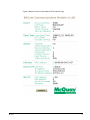
1
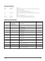
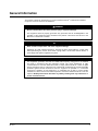
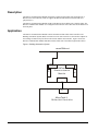
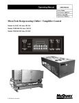
Installation and Maintenance Manual
IM 736-4
Group: Controls
Part Number: IM 736
Date: October 2006
Supercedes: IM 736-3
MicroTech II®
Chiller Unit Controller
BACnet® Communication Module (MS/TP)
• WSC
Water-Cooled Centrifugal, Single-Compressor
• WDC
Water-Cooled Centrifugal, Dual-Compressor
• WPV
Water-Cooled Centrifugal, Single-Compressor
• HSC
Water-Cooled Single-Compressor Centrifugal, Heat Recovery
• HDC
Water Cooled Dual-Compressor Centrifugal, Heat Recovery
• TSC
Water-Cooled Single-Compressor Centrifugal, Templifier™
• WMC
Water-Cooled Centrifugal, Magnetic Bearing
• WCC
Water-Cooled Centrifugal, Counterflow
• AGZ
Air-Cooled Global Scroll
• ACZ
Air-Cooled Scroll Condensing Unit
• WGZ
Water-Cooled Global Scroll
• AGS
Air-Cooled Global Screw
• WGS
Water-Cooled Global Screw
NOTICE
Use this manual to physically install the McQuay MicroTech II Communication Module into the chiller unit
controller and connect the chiller unit controller to your network. Use the appropriate McQuay Engineering
Data (ED), known as the Protocol Information document, to integrate the unit into your network. The Protocol
Information document contains addressing details, BACnet® and LONW ORKS® protocol information, and a list
of the data points available to the network. See the Reference Documents section of this manual for Protocol
Information document numbers. MicroTech II control integration literature is available from your local McQuay
International sales representative and www.mcquay.com.
© 2006 McQuay International
Contents
Figures ................................................................................................................................................... 2
Revision History.................................................................................................................................... 3
Reference Documents............................................................................................................................ 3
Limited Warranty .................................................................................................................................. 4
General Information .............................................................................................................. 5
Description ............................................................................................................................................ 6
Application ............................................................................................................................................ 6
Component Data.................................................................................................................................... 7
Connectors......................................................................................................................................... 7
Indicators ........................................................................................................................................... 7
Switch ................................................................................................................................................ 7
Installation.............................................................................................................................. 8
Mounting ............................................................................................................................................... 8
Installing a new BACnet Communication Module ............................................................................ 8
Mounting a BACnet Communication Module ................................................................................... 8
Replacing an Existing BACnet Communication Module .................................................................. 9
Unit Setup for BACnet Network Control ........................................................................................ 11
Integration ............................................................................................................................ 13
Access to Properties ............................................................................................................................ 13
Configuring the Unit Controller....................................................................................................... 13
Network Connection............................................................................................................................ 13
BACnet MS/TP Addressing ............................................................................................................ 13
Configure the BACnet Communication Module ................................................................................. 13
Upgrading BACnet Communication Module Firmware ...................................................................... 13
Changing the Network Settings ....................................................................................................... 16
Configuring the HTTP Interface...................................................................................................... 19
Service Information ............................................................................................................. 25
Test Procedures ................................................................................................................................... 25
Replaceable Parts List ......................................................................................................................... 25
Installation Kit ................................................................................................................................. 25
Appendix A: Hexadecimal Conversion Table ................................................................... 26
Figures
Figure 1. Building Automation System ................................................................................................. 6
Figure 2. BACnet Communication Module External Connectors (Top View) ...................................... 7
Figure 3. BACnet Communication Module Mounted in a Centrifugal Chiller Control Panel ............. 10
Figure 4. Serial Card Slot in Unit Controller....................................................................................... 11
Figure 5. Serial Card Slot Detail ......................................................................................................... 11
Figure 6. BACnet Communication Module HTTP Interface Page ...................................................... 15
Figure 7. Ping and Response ........................................................................................................... 19
Figure 8. MS/TP Data Transmission Rate Switch ............................................................................... 21
Figure 9. BACnet Communication Module Configuration Page ........................................................ 22
2
IM 736-4
Revision History
IM736-0
January 24, 2003
Initial release
IM736-1
May, 2005
Added WGS, WMC, HSC, HDC and TSC to front page and to the “Reference Documents” section
Edited part numbers in parts list
Added note in “Unit Setup for BACnet Control” section
Added note in “Changing the MSTP Data Transmission Rate” section
IM736-2
November, 2005
Added module location, power wiring, and set screen information for scroll and screw compressor
chillers.
Added Table 1 and Password table.
IM 736-3
June, 2006
Removed references to BACnet IP/Ethernet and moved them to IM 837
IM 736-4
October, 2006
Added new section for downloading firmware from mcquaybiz or mcquay.com
Reference Documents
Number
Company
Title
Source
ANSI/ASHRAE 1352001
American Society of Heating,
Refrigerating and AirConditioning Engineers
BACnet® A Data Communication Protocol for Building Automation
and Control Networks
www.ashrae.org
IMM AGS
McQuay International
MicroTech II Air-Cooled Screw Chiller Installation and Maintenance
Manual
www.mcquay.com
IOMM ACZ/AGZ
McQuay International
MicroTech II Air-Cooled Condensing Unit Installation, Operation,
and Maintenance Manual
www.mcquay.com
IOMM ACZ1
McQuay International
MicroTech II Air-Cooled Condensing Unit Installation, Operation,
and Maintenance Manual
www.mcquay.com
IOMM AGZ1
McQuay International
MicroTech II Air-Cooled Scroll Chiller Installation, Operation, and
Maintenance Manual
www.mcquay.com
IOMM AGZ
McQuay International
MicroTech II Air-Cooled Scroll Chiller Installation, Operation, and
Maintenance Manual
www.mcquay.com
IOMM WGZ
McQuay International
MicroTech II Water-Cooled Scroll Chiller Installation Manual
www.mcquay.com
IOMM WPV
McQuay International
MicroTech II Centrifugal Chiller Installation, Operation, and
Maintenance Manual
www.mcquay.com
IOMM WSCWDC
McQuay International
MicroTech II Chiller Unit Controller Installation, Operation, and
Maintenance Manual
www.mcquay.com
OM AGS
McQuay International
MicroTech II Air-Cooled Screw Chiller Operating Manual
www.mcquay.com
OM CentrifMicro II
McQuay International
MicroTech II Unit Controller for Centrifugal Chillers and Templifiers
Operating Manual
www.mcquay.com
ED 15062
McQuay International
MicroTech II Chiller Unit Controller Protocol Information, BACnet
MS/TP and LONWORKS® Networks
www.mcquay.com
OM WGS
McQuay International
MicroTech II Water-Cooled Screw Chiller Operating Manual
www.mcquay.com
OM WMC
McQuay International
MicroTech II Magnetic Bearing Compressor Chiller
www.mcquay.com
IOMM TSC
McQuay International
MicroTech II Templifier Single Compressor Centrifugal Installation,
Operation, and Maintenance Manual
www.mcquay.com
IM 736-4
3
Limited Warranty
Consult your local McQuay Representative for warranty details. Refer to Form 933-43285Y. To find
your local McQuay Representative, go to www.mcquay.com.
Notice
Copyright © 2006 McQuay International, Minneapolis MN. All rights reserved throughout the world.
McQuay International reserves the right to change any information contained herein without prior
notice. The user is responsible for determining whether this software is appropriate for his or her
application.
® ™ The following are trademarks or registered trademarks of their respective companies: BACnet
from the American Society of Heating, Refrigerating and Air-Conditioning Engineers, Inc.; LONWORKS
and LONMARK from Echelon, Inc.; Windows from Microsoft Corporation; McQuay, MicroTech II and
Templifier from McQuay International.
4
IM 736-4
General Information
This manual contains the information you need to install the BACnet® Communication Module,
incorporate it into the network, and maintain it.
!
WARNING
Electric shock hazard. Can cause personal injury or equipment damage.
This equipment must be properly grounded. Only personnel that are knowledgeable in the
operation of the equipment being controlled must perform connections and service to the
MicroTech II Chiller Unit Controller.
!
CAUTION
Static sensitive components. Can cause equipment damage.
Discharge any static electrical charge by touching the bare metal inside the control panel
before performing any service work. Never unplug cables, circuit board terminal blocks, or
power plugs while power is applied to the panel.
NOTICE
This equipment generates, uses and can radiate radio frequency energy and, if not installed
and used in accordance with this instruction manual, may cause interference to radio
communications. It has been tested and found to comply with the limits for a Class A digital
device, pursuant to part 15 of the FCC rules. These limits are designed to provide reasonable
protection against harmful interference when the equipment is operated in a commercial
environment. Operation of this equipment in a residential area is likely to cause harmful
interference in which case the user will be required to correct the interference at his or her own
expense. McQuay International disclaims any liability resulting from any interference or
for the correction thereof.
IM 736-4
5
Description
The BACnet Communication Module incorporates a MicroTech II Chiller Unit Controller into a
BACnet Local Area Network (LAN). It supports the BACnet MS/TP (EIA 485) data link layer
(physical layer).
The BACnet Communication Module mounts in the MicroTech II Chiller Unit Controller panel. The
BACnet Communication Module is a rectangular metal enclosure with connectors and an indicator on
the front panel.
Application
The BACnet Communication Module connects the MicroTech II Chiller Unit Controller to the
Building Automation System (BAS) on a BACnet Local Area Network. It is the interface adapter for
the exchange of BACnet objects between the network and the unit controller. Figure 1 shows the
BACnet Communication Module and MicroTech II Chiller Unit Controller integrated into a BAS.
Figure 1. Building Automation System
RS-485 BACn et
RS-485
(Iso lat ed )
24
VAC
Et h er n et
BACn et
Co m m u n icat io n
Mo d u le
PWR
Ch iller (RS-232)
Ser ial Car d
Po r t
Micr o Tech II
Ch iller Un it Co n t r o ller
6
IM 736-4
Component Data
Figure 2 shows the external connectors of the BACnet Communication Module.
Figure 2. BACnet Communication Module External Connectors (Top View)
BCM
Chiller (RS232)
MCQ–3302742 Rev.___
BCM Ethernet
PWR
BCM RS485
(Isolated)
24VAC
Connectors
The BACnet Communication Module uses two of the connectors mounted on the top panel.
Chiller (RS232)
This connector is the interface between the MicroTech II Chiller Unit Controller and the BACnet
Communication Module.
BCM RS485 (Isolated)
This connector is the interface to the BACnet MS/TP network.
24 VAC
This connector is for the input power.
Indicators
The BACnet Communication Module has one indicator mounted on the top panel.
PWR
This indicator lights when power is applied to the BACnet Communication Module.
Switch
The BACnet Communication Module has one switch to condition BACnet Communication Module
for different data transmission rates on an MS/TP network. This switch is located inside BACnet
Communication Module (see Figure 8.)
Switch
This slide switch has two positions: one for 9600 and 19200 bps (baud) and one for 38400 bps. The
default position is 38400 bps.
IM 736-4
7
Installation
The BACnet Communication Module can be factory or field installed. The sales representative
should use the appropriate chiller selection software program in McQuayTools™ to include the
BACnet Communication Module with the unit.
For field installation, the BACnet Communication Module kit may be ordered through the McQuay
sales office or through McQuay Parts. The BACnet Communication Module kit includes the BACnet
Communication Module, cables, serial card connector, and this installation manual. The BACnet
Communication Module is also sold separately (i.e. just the module itself) through McQuay Parts.
See Replaceable Parts List for part numbers.
Mounting
Installing a new BACnet Communication Module
You can add a new BACnet Communication Module to the MicroTech II control system in order to
incorporate it into an existing BACnet network.
Mounting a BACnet Communication Module
To mount a BACnet Communication Module:
1. Remove power from the MicroTech II Chiller Unit Controller.
2. See Table 1 for BACnet Communication Module location and mount the module. Where studs
are indicated, mount the module on the studs with the hardware included in the kit (see Figure 3).
For other locations, drill mounting holes using the module as a template, exercising care not to
drill through to a component or wiring. Secure the module with machine screws.
Table 1. Module Location and Power Wiring
Chiller Model
Power Connection Terminals
Mounting Location
AGS-B
HOT>TB1-60, COM>TB1-75
Studs in control panel
AGZ-A/ACZ-A
HOT>31-32, COM>21-28
Studs inside left-hand control panel door
AGZ-B/ACZ-B
HOT>42-54, COM>81-84
Upper right-hand corner of control panel door
AGS-C
HOT>TB1-60, COM>TB1-75
Studs in control panel
HSC
HOT>UTB1-70, COM>UTB1-71
Studs on door of the unit control panel
HDC
HOT>UTB1-70, COM>UTB1-71
Studs on door of the unit control panel
TSC
HOT>UTB1-70, COM>UTB1-71
Studs on door of the unit control panel
WCC
HOT>UTB1-70, COM>UTB1-71
Studs on door of the unit control panel
WDC
HOT>UTB1-70, COM>UTB1-71
Studs on door of the unit control panel
WGS
HOT>42-54, COM>81-84
Mount horizontally behind the unit controller
WGZ
HOT>31-43, COM>56-60
Upper right-hand corner of control panel door
WMC
HOT>UTB1-70, COM>UTB1-71
Studs on top of the panel door
WPV
HOT>UTB1-70, COM>UTB1-71
Studs on door of the unit control panel
WSC
HOT>UTB1-70, COM>UTB1-71
Studs on door of the unit control panel
NOTES:
a.
If a range of terminal numbers is given, such as 42-54, connect to any terminal in the range.
b. The two-pin power connector wires are marked HOT and COM (common).
3. Locate the Serial Card slot on the MicroTech II Chiller Unit Controller (see Figure 4.)
4. Remove the cover from the Serial Card slot if it has not already been removed. Use a small
screwdriver to pry the cover off from one end.
5. Remove the plastic knock-out in the cover.
8
IM 736-4
6. Figure 5 details the Serial Card slot with the 8-pin plug that mates to the receptacle on the RS 232
Serial Interface Card. Grasp the RS 232 Serial Interface Card, with the network connector on the
underside. The 8-pin receptacle must mate to the 8-pin plug in the MicroTech II Chiller Unit
Controller. The plug has a guide on each end to direct the card into the mating guide on the
receptacle.
Note:
This operation relies more on feeling the RS 232 Serial Interface Card into the connector
than seeing the connectors mate.
7. Insert the RS 232 Serial Interface Card, pointing up, into the slot, rolling it into a level position as
you move it into the slot.
8. Keeping the RS 232 Serial Interface Card level, move it in the slot until you feel the connectors
line up. The correct position seems to be level, toward the left side of the slot, and down slightly
from the top.
9. When you feel the connectors align, press the RS 232 Serial Interface Card into the connector.
Verify that it is firmly seated in the connector.
10. Replace the cover on the Serial Card slot. Slip the cover over the network connector plug.
11. Connect the BACnet Communication Module to the MicroTech II Chiller Unit Controller.
a. Plug the Serial Cable in both the RS 232 Serial Interface Card and the BACnet
Communication Module’s Chiller (RS232) connector.
b. Route the Serial Cable across the hinge and over to the BACnet Communication Module.
12. Connect power to the BACnet Communication Module.
a. Plug the power wires into the BACnet Communication Module’s 24 VAC connector and
neatly route the wires to the unit terminals as indicated in Table , using existing raceways
and/or self-adhesive wire bases whenever possible.
13. Connect the BACnet Communication Module to the network (see Figure 2.)
a. Route the network cable through a knockout to the appropriate connector on the BACnet
Communication Module.
14. Restore power to the MicroTech II Chiller Unit Controller.
Replacing an Existing BACnet Communication Module
To replace a BACnet Communication Module
1.
2.
3.
4.
5.
6.
7.
Remove power from the MicroTech II Chiller Unit Controller.
Remove the power wires from the terminal block.
Locate the Serial Card slot on the MicroTech II Chiller Unit Controller (see Figure 4.)
Pull the network cable connector from the BACnet Communication Module.
Remove the cover from the Serial Card slot. Use a small screwdriver to pry it off from one end.
Grasp the RS 232 Serial Interface Card and carefully pull it from the controller.
Install the new RS 232 Serial Interface Card:
a. Grasp the RS 232 Serial Interface Card, with the network connector on the underside. The 8pin receptacle must mate to the 8-pin plug in the MicroTech II Chiller Unit Controller. The
plug has a guide on each end to direct the RS 232 Serial Interface Card into the mating guide
on the receptacle. Figure 5 details the Serial Card slot showing how the 8-pin plug mates to
the receptacle on the RS 232 Serial Interface Card.
Note:
b.
IM 736-4
This operation relies more on feeling the RS 232 Serial Interface Card into the
connector than seeing the connectors mate.
Insert the RS 232 Serial Interface Card, pointing up, into the slot, rolling it into a level
position as you move it into the slot.
9
c.
Keeping the RS 232 Serial Interface Card level, move it in the slot until you feel the
connectors line up. The correct position seems to be level, toward the left side of the slot,
and down slightly from the top.
d. When you feel the connectors align, press the RS 232 Serial Interface Card into the
connector. Verify that it is firmly seated in the connector.
8. Replace the cover on the Serial Card slot. Slip the cover over the network connector plug.
9. Remove the BACnet Communication Module from the control panel door.
10. Mount the BACnet Communication Module on the studs with the hardware included in the kit.
(see Figure 3.)
11. Connect the BACnet Communication Module to the MicroTech II Chiller Unit Controller.
a. Plug the Serial Cable in both the RS 232 Serial Interface Card and the BACnet
Communication Module.
b. Route the cable across the hinge and over to the BACnet Communication Module.
12. Connect power to the BACnet Communication Module.
a. Plug the power wires into the BACnet Communication Module PWR connector and route
the wires per instructions in paragraph 13 on page 9.
13. Connect the BACnet Communication Module to the network (see Figure 2.)
a. Route the network cable through a knockout and to the appropriate connector on the BACnet
Communication Module.
14. Restore power to the MicroTech II Chiller Unit Controller.
Figure 3. BACnet Communication Module Mounted in a Centrifugal Chiller Control Panel
Power Cables
BCM Serial Cable
Network Cable
Serial Card Connector
10
IM 736-4
Figure 4. Serial Card Slot in Unit Controller
®
Ai r Condition ing
Serial Card Slot
IDC15
ID7
ID6
ID5
ID4
ID3
ID2
Y4
Y3
Y2
Y1
VG0
ID1
J5
J4
VG
J19
ID15
8-Pin Connector
for Serial Card
ID15H
Figure 5. Serial Card Slot Detail
Unit Setup for BACnet Network Control
Setup for MicroTech II Centrifugal Chiller Network Control:
1.
2.
3.
4.
Disable the chiller. The chiller should not be operating while performing this setup.
At the chiller touchscreen interface panel:
a. In the SETPOINTS MODE screen, set the #9 setpoint, BAS Protocol to BACnet. Use the
Operator Password of “2001.”
b. In the SETPOINTS MODE screen, set the #3 setpoint, Control Source to Local.
Verify with the chiller/control company technician that the chiller is operational on BAS.
In the SETPOINTS MODE screen, set the #3 setpoint, Control Source to BAS.
Setup for all Other MicroTech II Chillers Network Control:
1.
2.
IM 736-4
Set the Set Unit Setpoint screen 1 initially to Source = Keypad.
Change the Protocol to BACnet in the applicable menu screen shown in the table below.
11
Table 2. MicroTech II Chiller Unit Controller Menu Screens
Model
Menu Screen
Password
AGZ-A
ACZ-A
AGZ-B
ACZ-B
AGS-B
AGS-C
WGS
WGZ
9
6
9
7
12
14
15
10
2001
2001
2001
2001
8945
8453
8745
2001
NOTE: Models AGZ-A/B, ACZ-A/B, and WGZ have one unit controller, while models AGS-B/C and WGS have one unit controller and multiple
circuit controllers. Unit settings for AGS-B/C and WGS models are adjusted on the unit controller.
3.
4.
12
Verify with the chiller/control company technician that the chiller is operational on a BAS.
Set the Set Unit Setpoint screen 1 to Source = Network.
IM 736-4
Integration
Access to Properties
To access a property, you must specify the object identifier including the device object identifier or
the object name including the device object name and the property identifier. See the MicroTech II
Chiller Unit Protocol Information document (ED 15062) for details.
Configuring the Unit Controller
The MicroTech II Chiller Unit Controller and BACnet Communication Module are designed,
programmed, and configured at the factory. The unit is ready to operate with the default parameter
values in the unit controller after you change the default parameter values in the HTTP Interface. If
you need to change the default values in the MicroTech II Chiller Unit Controller, see the appropriate
Operation Manual for default values and keypad operating instructions. Use the MicroTech II Chiller
Unit Controller Protocol Information document (ED 15062) for descriptions of the HTTP Interface
variables.
Network Connection
BACnet MS/TP Addressing
The BACnet MS/TP Medium Access Control (MAC) address is a variable one-octet address that
must be set during the BACnet Communication Module configuration. See your system integrator for
a MAC address. This address and two other parameters for MS/TP networks are available for
adjusting in the BACnet Configuration page (see Configure the BACnet Communication Module
section.) The MS/TP MAC address must be unique to the MS/TP network. Valid MAC addresses run
from 0 to 127.
Configure the BACnet Communication Module
The BACnet Communication Module is configured using an HTML Interface page in an HTTP
server residing in the BACnet Communication Module. You can only access the HTTP Interface via
the BACnet Communication Module Ethernet port at its IP address. In order to access this page, your
computer must be on a similar subnet as the BACnet Communication Module, which is shipped set to
a default IP subnet mask (255.255.0.0), and IP address (172.16.5.8.). You must change the network
settings on your computer to closely match the subnet. After you have configured the BACnet
Communication Module, you should restore the original network settings to your computer. The
configuration process is the same regardless of your computer’s operating system.
Figure 6 shows the HTTP Interface page. It has a total of six areas of information: three are BACnet
specific and three are network specific. The parameters that require setting depend on the data link
layer of the BAS network. Device, Date/Time, and Alarms require settings for all BACnet networks.
BACnet MS/TP networks require network settings.
Upgrading BACnet Communication Module Firmware
If an update to the BACnet Communication Module firmware is required or recommended, you must
follow all of the procedures previously described in IM 736 to verify proper installation, network
setup and configuration. Refer to the following sections: Installing a new BACnet Communication
Module, Unit Setup for BACnet Network Control, and Configure the BACnet Communication
Module.
IM 736-4
13
Once these steps are complete and your PC is on a similar IP address and subnet mask as the BACnet
Communication Module, follow the instructions listed below to download the firmware from the
McQuay website.
1. Go to www.mcquay.com\Products\Controls\Application Software and click on the “MicroTech II
Chiller BACnet Communication Module v1.xx Update” file.
2. Save the contents of the zip file to a selected folder on your hard drive.
3. Open the zip file from your hard drive and print this section of IM 736.
4. Verify that the BACnet Communication Module is set to the default IP address of 172.16.5.
Note:
5.
6.
7.
Step 4 is required so that the automatic firmware download process works properly.
Double click on the transfer.bat file to install the BACnet Communication Module firmware.
Cycle power to the BACnet Communication Module.
Verify that the correct BACnet Communication Module firmware version has been downloaded.
•
Open Internet Explorer.
•
Type the BACnet Communication Module’s IP address in the web browser.
•
The BACnet Communication Module User Interface will open and you should see
“BACnet Communication Module v1.xx” text at the top of the page.
If you have any questions or concerns about the firmware download process, please contact the
McQuay Controls Customer Support Team at 1-866-4McQuay (462-7829).
14
IM 736-4
Figure 6. BACnet Communication Module HTTP Interface Page
IM 736-4
15
Changing the Network Settings
The BACnet Communication Module is assigned a factory default IP address and Subnet Mask.
These are only temporary but are required so that you know where to access the BACnet
Communication Module in order to change network parameters. The BACnet Communication
Module is configured using a minimal HTTP server that is accessed using Internet Explorer®.
Required Tools
You need the following tools to configure the BACnet Communication Module for network
operation:
• PC with Ethernet card and TCP/IP protocol.
• Internet Explorer browser.
• Ethernet Cable (Either an Ethernet crossover cable for direct connection or a standard Ethernet
cable for connecting through a hub.)
Procedure
The procedure for changing the network settings varies depending the operating system in your
computer.
You must access the HTTP Interface page at its IP address. In order to access the configuration page,
your computer must be on the same subnet as the BACnet Communication Module. Doing so will
allow you to:
1.
Change the network settings on your computer and options in Internet Explorer.
2.
Access the HTTP Interface page to change the BACnet Communication Module parameters.
3.
Change the network settings of your computer and Internet Explorer options back to the way they
were before the configuration process.
Details regarding each of these items are described below.
To Change the IP address in the BACnet Communication Module:
Note:
1.
2.
3.
4.
5.
6.
You can only connect to the BACnet Communication Module via the Ethernet port. To
install the BACnet Communication Module using an MS/TP (RS-485) network, you must
connect via an Ethernet cable directly to the BACnet Communication Module, then change
the settings for the MS/TP network, and finally install the BACnet Communication Module
in the MS/TP network.
Connect to the BACnet Communication Module via the Ethernet port.
Request the Subnet Mask of the network for the BACnet Communication Module from the
network administrator.
Request an IP address for the BACnet Communication Module from the network administrator.
Change the network settings on your computer to access the BACnet Communication Module.
Use the appropriate procedure below for your operating system.
Open the browser on your computer.
In the Internet Explorer, go to Tools/Internet Options/Connections/LAN Settings.
a. Note the selections for future reference.
b. Verify that Automatically Detect Settings, Use Automatic Configuration Script, and Use a
Proxy Server for Your LAN are not selected.
Note:
7.
16
Verify that these settings are disabled to confirm that the changes you make to the
BACnet Communication Module with the browser take effect.
Type http://172.16.5.8/ in the Address box of the browser and press the Enter key to access the
BACnet Communication Module.
IM 736-4
8.
Make changes to the configuration file in the BACnet Communication Module (see the Changing
the MS/TP Data Transmission Rate section.)
9. Reboot the BACnet Communication Module to change the settings.
10. In the browser on your computer:
a. Go to Tools/Internet Options/Connections/LAN Settings.
b. Restore the settings as noted in Step 6a.
11. Restore the network settings on your computer (see following page for instructions based on your
operating system.)
Network Settings for Microsoft Windows® 95 and 98
To change the network setting in Microsoft Windows 95 and 98 computer:
1. Open the Control Panel on your computer.
2. Open the Network Applet.
3. Select the TCP/IP-Ethernet card combination on your computer.
4. Select the Properties button.
5. Select the IP Address tab.
6. Note the IP address and Subnet mask if they have values or that Obtain IP address automatically
is selected.
7. Select Specify an IP address.
8. Change the Subnet mask to 255.255.0.0.
9. Change the IP address to 172.16.X.X (where X.X is unique on the subnet but not 172.16.5.8).
10. Click the OK button.
11. Reboot your computer to change the Subnet Mask and IP address.
To restore the network setting in Microsoft Windows 95 and 98 computer:
1. Open the Control Panel on your computer.
2. Open the Network Applet.
3. Select the TCP/IP-Ethernet card combination on your computer.
4. Select the Properties button.
5. Select the IP Address tab.
6. Restore the settings noted as previously noted.
7. Click the OK button.
8. Reboot your computer to restore the original Subnet Mask and IP address.
Network Setting for Microsoft Windows NT
To change the network settings in a Microsoft Windows NT computer:
1. Open the Control Panel on your computer.
2. Open the Network Applet.
3. Select the Protocols tab.
4. Select the TCP/IP-Ethernet card combination on your computer.
5. Select the Properties button.
6. Select the appropriate adapter.
7. Note the IP address and Subnet mask if they have values or that Obtain IP address automatically
is selected.
8. Select Specify an IP address.
9. Change the Subnet mask to 255.255.0.0.
10. Change the IP address to 172.16.X.X (where X.X is unique on the subnet but not 172.16.5.8).
11. Click on the Apply button.
IM 736-4
17
To restore the network settings in a Microsoft Windows NT computer:
1. Open the Control Panel on your computer.
2. Open the Network Applet.
3. Select the Protocols tab.
4. Select the TCP/IP-Ethernet card combination on your computer.
5. Select the Properties button.
6. Select the appropriate adapter.
7. Restore the settings as previously noted.
8. Click the Apply button.
Network Setting for Microsoft Windows 2000
To change the network settings in a Microsoft Windows 2000 computer:
1. Select My Network Places on the desktop and right click.
2. Open Properties.
3. Select Local Area Connections and right click.
4. Open Properties.
5. Select TCP/IP.
6. Click on Properties button.
7. Note settings for future reference.
8. Select Use the following IP address.
9. Change the Subnet mask to 255.255.0.0.
10. Change the IP address to 172.16.X.X (where X.X is unique on the subnet but not 172.16.5.8).
11. Click OK.
To restore the network settings in a Microsoft Windows 2000 computer:
1. Select My Network Places on the desktop and right click.
2. Open Properties.
3. Select Local Area Connections and right click.
4. Open Properties.
5. Select TCP/IP.
6. Restore the network settings as previously noted.
7. Click OK.
Test Network Communications
You can determine whether your computer is properly configured to access the BACnet
Communication Module.
To test whether your computer is properly addressed to communicate with the
BACnet Communication Module:
1.
2.
3.
4.
18
Open a DOS window (go to Start button\Programs\Accessories\Command Prompt.)
Type “ping 172.16.5.8” at the DOS prompt.
Press Enter.
Observe response. See Figure 7 for a typical response.
IM 736-4
Figure 7. Ping and Response
Configuring the HTTP Interface
To change the parameters in the HTTP Interface, select the Configure button at the bottom of the
HTTP Interface home page. Figure 6 shows the Configuration page in the HTTP Interface.
To Configuring the HTTP Interface:
1. Connect to the BACnet Communication Module via the Ethernet port for configuration.
2. Browse to the HTTP Interface page Figure 6
3. Select the Configure button. The HTTP Configuration page opens (see Figure 9.)
4. Enter the password. Default password is 1234.
5. Adjust the parameters for particular network.
Note:
The factory default setting for the BACnet Communication Module’s MS/TP data
transmission rate is 38400 bps. If this is the data transmission rate you want for your
network, skip step 6.
6.
To install the BACnet Communication Module on an MS/TP network, set the Data Transmission
Rate switch to the data transmission rate of your network. (see Changing the MS/TP Data
Transmission Rate section.) Select the Change or Reboot button to set the changes into the
BACnet Communication Module. You only need to reboot for the parameters that indicate a
reboot is necessary.
7. Select the Home button to return to the HTTP Interface page.
8. Verify that the changes were made. If the changes were not made, verify that the LAN Settings
are not selected in Internet Explorer.
9. Close your browser.
10. Remove the connection to Ethernet port you made in Step 1.
Changing the MS/TP Data Transmission Rate
The MS/TP Data Transmission Rate is changed with a switch inside BACnet Communication
Module. The switch has two positions: one for 9600 bps and 19200 bps and one for 38400 bps. The
switch is shipped from the factory in the 38400 bps position. You do not have to change this switch
if your network uses 38400 bps. In addition to setting this switch, you must also set the transmission
rate on the HTTP interface. After you set the data transmission rate, verify that you have removed the
Ethernet cable from the BACnet Communication Module so that MS/TP communications can proceed
efficiently.
IM 736-4
19
!
WARNING
Electric shock hazard. Can cause personal injury or equipment damage.
This equipment has exposed electrical connections inside BACnet Communication Module.
Only personnel that are knowledgeable in the operation of this equipment must perform
connections and service to the BACnet Communication Module.
To Change the MS/TP Data Transmission Rate:
1. Remove power from the BACnet Communication Module.
2. Remove the four screws that secure to cover to the BACnet Communication Module and lift the
cover.
3. Locate the MS/TP data transmission rate switch mounted on top of the isolation module. Figure
8 shows the inside of the BACnet Communication Module when the cover is removed.
Note:
4.
5.
6.
Carefully (without touching the connections on the transformer or any other wires) slide the
switch to the position you want. Use a non-conductive tool.
Replace the cover and the four screws that secure the cover.
Restore power to the BACnet Communication Module.
Note:
20
The default position for this switch is in the High (H) (38400 bps) position.
The Isolator Module may have jumpers to select the baud rate instead of the switch as
shown below. See the silk screen next to the jumpers for properly setting these jumpers.
IM 736-4
Figure 8. MS/TP Data Transmission Rate Switch
Processor
Isolat or
Transf orm
MS/TP Dat a Transmission Rat e
Def ault Posit ion is High
Note: This switch has been replaced with jumpers on newer versions of
the isolator module. Contact the McQuay Controls Customer Support
group with any questions regarding this switch.
Note: Drawing shown as mounted on the chiller panel door with connectors on top.
Changing Parameters in the HTTP Interface Page
Password
In order to change any parameters, you must enter a password in the Configuration page. The initial
password is 1234. You can change this password by following these steps: enter your password, enter
the new password, and reboot.
IM 736-4
21
Figure 9. BACnet Communication Module Configuration Page
Configurable Parameters
Table 3 defines the configurable parameters of the BACnet Communication Module in the same order
as they appear on the HTTP Configuration page (see Figure 9). Change parameters as required for
you network.
22
IM 736-4
Table 3. Configurable Parameters
Section
Password
Parameter
Password
New Password
Device
Device Instance
LAN Type
MS/TP
Client Timeout
Normal or Busy Network/The time
the BACnet Communication
Module waits for a response to a
ConfirmedEventNotification.
Limits the frequency, in minutes,
of Who Is requests the BACnet
Communication Module issues.
Password that allows the BACnet
Communication Module to be
reinitialized from the network.
Who Is Frequency
Reinit Password
Date/Time
Alarms
Year
Current Year
Month (1..12)
Current Month
Day (1..31)
Current Day
Initial Value/Note
1234
3000/This must be unique
throughout the entire BACnet
network.
BACnet/IP
Normal/Setting to Normal gives
ADPU timeout = 3000ms. Setting
to Busy Network gives ADPU
timeout = 10000 ms.
1 (per minute)
Blank/Blank indicates no password
is required. If a password is
entered, a password is required
before a BACnet client can
reinitialize this BACnet
Communication Module.
If the network has a BACnet Time
Master the Time and Date
parameters are set automatically.
Hours (0..23)
Current Hours
Minutes (0..59)
Current Minutes
Seconds (0..59)
Current Seconds
UCT Offset (-720..720)
Daylight Savings?
Difference, in minutes, of the
Universal Coordinated Time and
local time.
Yes or No
Set New Time?
Yes or No
Enabled?
Problem Priority (0..255)
Yes or No/Enabling this feature
provides alarm annunciation from
the BACnet Communication
Module to a BACnet Client.
BACnet Clients can also poll
variables in BACnet
Communication Module for alarm
information. See the Protocol
Information document (ED 15062)
for details.
0-4194303/Device Object of the
BACnet device that receives the
alarm notification.
Process ID used at the receiving
BACnet device to determine the
response action to the alarm
notification.
Priority for Problem Alarms
Fault Priority (0..255)
Priority for Fault Alarms
0
Warning Priority (0..255)
Priority for Warning Alarms
255
Alarm Destination Device Instance
Alarm Destination Process ID
IM 736-4
Value (Range)/Definition
Enter the password before
changing any parameters on this
page.
You can change the password;
enter the new password here.
0-4194303/Device Instance of the
BACnet Communication Module
No/Must be set to No for a
BACnet client to synchronize the
time on the network.
No/If the network does not have a
BACnet Time Master, you must set
the time manually.
No/Yes enables the BACnet
Communication Module to send a
ConfirmedEventNotification
message to a single BACnet device
whenever an alarm occurs in the
chiller. This message has an Event
Type = Complex Event and has
proprietary properties in its Event
Values section. Not all BACnet
devices can accept this message.
1
1/May be changed to suit the BAS
preference.
0
23
Section
Parameter
Value (Range)/Definition
Initial Value/Note
MS/TP
MAC address
0-127/Media Access Control
Address (unique hardware address)
of the BACnet Communication
Module.
Max Masters
Maximum Number of Master
Controllers currently on the
network that the BACnet
Communication Module can poll.
Maximum Number of Information
Frames the BACnet
Communication Module can send
before it must pass the token.
1/See the BAS systems integrator.
This value must be entered as a
hexadecimal value. See Appendix
A: Hexadecimal Conversion on
page 26.
127 Master Controllers/ See the
BAS system integrator. BAS
integrators can decrease this value
to improve network performance.
5 Frames
Max Info Frames
Baudrate
9600 bps, 19200 bps, and
38400 bps/Data Transmission rate
on the MS/TP network
38400 bps/ See the BAS system
integrator. Be sure to set the
Switch to the correct position.*
*Although 76800 bps selectable, it is not a valid speed.
24
IM 736-4
Service Information
Test Procedures
If you can control the unit from its keypad, but you are not able to communicate with unit via the
network:
• Check the network wiring
• Check communications
• Use the standard TCP/IP suite of protocols to check your connectivity with other devices.
For example, type “ping <IP address of the MicroTech II BACnet Communications
Module>.” If you get a response from that IP address, you are connected to the BACnet
Communication Module.
If the BACnet Communication Module still does not respond, call the McQuay Controls Customer
Support group at 866-4MCQUAY (866-462-7829).
Replaceable Parts List
Installation Kit
IM 736-4
Description
Part No.
MicroTech II BACnet Communication Module-MS/TP kit
350147404
MicroTech II BACnet Communication Module, no RS 232 Serial
Interface Card
330274201
MicroTech II BACnet Communication Module Serial Cable (72 in.)
330274204
RS 232 Serial Interface Card
330343102
Connector-Wago
330803003
Tool-Wago Connector
330803050
25
Appendix A: Hexadecimal Conversion Table
Dec
0
1
2
3
4
5
6
7
8
9
10
11
12
13
14
15
16
17
18
19
20
21
22
23
24
25
26
27
28
29
30
31
26
Hex
0
1
2
3
4
5
6
7
8
9
A
B
C
D
E
F
10
11
12
13
14
15
16
17
18
19
1A
1B
1C
1D
1E
1F
Dec
32
33
34
35
36
37
38
39
40
41
42
43
44
45
46
47
48
49
50
51
52
53
54
55
56
57
58
59
60
61
62
63
Hex
20
21
22
23
24
25
26
27
28
29
2A
2B
2C
2D
2E
2F
30
31
32
33
34
35
36
37
38
39
3A
3B
3C
3D
3E
3F
Dec
64
65
66
67
68
69
70
71
72
73
74
75
76
77
78
79
80
81
82
83
84
85
86
87
88
89
90
91
92
93
94
95
Hex
40
41
42
43
44
45
46
47
48
49
4A
4B
4C
4D
4E
4F
50
51
52
53
54
55
56
57
58
59
5A
5B
5C
5D
5E
5F
Dec
96
97
98
99
100
101
102
103
104
105
106
107
108
109
110
111
112
113
114
115
116
117
118
119
120
121
122
123
124
125
126
127
Hex
60
61
62
63
64
65
66
67
68
69
6A
6B
6C
6D
6E
6F
70
71
72
73
74
75
76
77
78
79
7A
7B
7C
7D
7E
7F
IM 736-4
This document contains the most current product information as of this printing. For the most current product
information, please go to www.mcquay.com. All McQuay equipment is sold pursuant to McQuay’s Standard Terms
and Conditions of Sale and Limited Warranty.
(763) 553-5330 • www.mcquay.com