1
View Safety Info
SVM204-A
OUTBACK® 185
For use with machine code number:
October, 2010
11516
Return to Master TOC
View Safety Info
View Safety Info
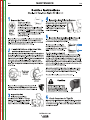
Safety Depends on You
Return to Master TOC
Return to Master TOC
RETURN TO MAIN MENU
Lincoln arc welding and cutting
equipment is designed and built
with safety in mind. However,
your overall safety can be
increased by proper installation
. . . and thoughtful operation on
your part. DO NOT INSTALL,
OPERATE OR REPAIR THIS
EQUIPMENT WITHOUT READING THIS MANUAL AND THE
SAFETY PRECAUTIONS CONTAINED THROUGHOUT. And,
most importantly, think before you
act and be careful.
View Safety Info
Return to Master TOC
SERVICE MANUAL
Copyright © Lincoln Global Inc.
• World's Leader in Welding and Cutting Products •
• Sales and Service through Subsidiaries and Distributors Worldwide •
Cleveland, Ohio 44117-1199 U.S.A. TEL: 1.888.935.3877 FAX: 216.486.1751 WEB SITE: www.lincolnelectric.com
SAFETY
Return to Master TOC
i
i
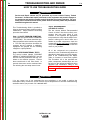
WARNING
CALIFORNIA PROPOSITION 65 WARNINGS
Diesel engine exhaust and some of its constituents
The engine exhaust from this product contains
are known to the State of California to cause canchemicals known to the State of California to cause
cer, birth defects, and other reproductive harm.
cancer, birth defects, or other reproductive harm.
The Above For Gasoline Engines
The Above For Diesel Engines
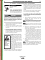
ARC WELDING can be hazardous. PROTECT YOURSELF AND OTHERS FROM POSSIBLE SERIOUS INJURY OR DEATH.
KEEP CHILDREN AWAY. PACEMAKER WEARERS SHOULD CONSULT WITH THEIR DOCTOR BEFORE OPERATING.
Return to Master TOC
Return to Master TOC
Read and understand the following safety highlights. For additional safety information, it is strongly recommended that you
purchase a copy of “Safety in Welding & Cutting - ANSI Standard Z49.1” from the American Welding Society, P.O. Box 351040,
Miami, Florida 33135 or CSA Standard W117.2-1974. A Free copy of “Arc Welding Safety” booklet E205 is available from the
Lincoln Electric Company, 22801 St. Clair Avenue, Cleveland, Ohio 44117-1199.
BE SURE THAT ALL INSTALLATION, OPERATION, MAINTENANCE AND REPAIR PROCEDURES ARE
PERFORMED ONLY BY QUALIFIED INDIVIDUALS.
FOR ENGINE
powered equipment.
1.h. To avoid scalding, do not remove the
radiator pressure cap when the engine is
hot.
1.a. Turn the engine off before troubleshooting and maintenance
work unless the maintenance work requires it to be running.
____________________________________________________
1.b.Operate engines in open, well-ventilated
areas or vent the engine exhaust fumes
outdoors.
____________________________________________________
1.c. Do not add the fuel near an open flame welding arc or when the engine is running. Stop
the engine and allow it to cool before refueling to prevent spilled fuel from vaporizing on
contact with hot engine parts and igniting. Do
not spill fuel when filling tank. If fuel is spilled,
wipe it up and do not start engine until fumes
have been eliminated.
____________________________________________________
1.d. Keep all equipment safety guards, covers and devices in position and in good repair.Keep hands, hair, clothing and tools
away from V-belts, gears, fans and all other moving parts
when starting, operating or repairing equipment.
____________________________________________________
Return to Master TOC
1.e. In some cases it may be necessary to remove safety
guards to perform required maintenance. Remove
guards only when necessary and replace them when the
maintenance requiring their removal is complete.
Always use the greatest care when working near moving
parts.
___________________________________________________
1.f. Do not put your hands near the engine fan.
Do not attempt to override the governor or
idler by pushing on the throttle control rods
while the engine is running.
ELECTRIC AND
MAGNETIC FIELDS
may be dangerous
2.a. Electric current flowing through any conductor causes
localized Electric and Magnetic Fields (EMF). Welding
current creates EMF fields around welding cables and
welding machines
2.b. EMF fields may interfere with some pacemakers, and
welders having a pacemaker should consult their physician
before welding.
2.c. Exposure to EMF fields in welding may have other health
effects which are now not known.
2.d. All welders should use the following procedures in order to
minimize exposure to EMF fields from the welding circuit:
2.d.1. Route the electrode and work cables together - Secure
them with tape when possible.
2.d.2. Never coil the electrode lead around your body.
2.d.3. Do not place your body between the electrode and
work cables. If the electrode cable is on your right
side, the work cable should also be on your right side.
2.d.4. Connect the work cable to the workpiece as close as
possible to the area being welded.
___________________________________________________
1.g. To prevent accidentally starting gasoline engines while
turning the engine or welding generator during maintenance
work, disconnect the spark plug wires, distributor cap or
magneto wire as appropriate.
2.d.5. Do not work next to welding power source.
OUTBACK® 185
SAFETY
Return to Master TOC
Return to Master TOC
ii
ELECTRIC SHOCK can kill.
ARC RAYS can burn.
3.a. The electrode and work (or ground) circuits
are electrically “hot” when the welder is on.
Do not touch these “hot” parts with your bare
skin or wet clothing. Wear dry, hole-free
gloves to insulate hands.
4.a.
Use a shield with the proper filter and cover
plates to protect your eyes from sparks and
the rays of the arc when welding or observing
open arc welding. Headshield and filter lens
should conform to ANSI Z87. I standards.
3.b. Insulate yourself from work and ground using dry insulation.
Make certain the insulation is large enough to cover your full
area of physical contact with work and ground.
4.b. Use suitable clothing made from durable flame-resistant
material to protect your skin and that of your helpers from
the arc rays.
In addition to the normal safety precautions, if welding
must be performed under electrically hazardous
conditions (in damp locations or while wearing wet
clothing; on metal structures such as floors, gratings or
scaffolds; when in cramped positions such as sitting,
kneeling or lying, if there is a high risk of unavoidable or
accidental contact with the workpiece or ground) use
the following equipment:
• Semiautomatic DC Constant Voltage (Wire) Welder.
• DC Manual (Stick) Welder.
• AC Welder with Reduced Voltage Control.
4.c. Protect other nearby personnel with suitable, non-flammable
screening and/or warn them not to watch the arc nor expose
themselves to the arc rays or to hot spatter or metal.
3.c. In semiautomatic or automatic wire welding, the electrode,
electrode reel, welding head, nozzle or semiautomatic
welding gun are also electrically “hot”.
3.d. Always be sure the work cable makes a good electrical
connection with the metal being welded. The connection
should be as close as possible to the area being welded.
3.e. Ground the work or metal to be welded to a good electrical
(earth) ground.
3.f. Maintain the electrode holder, work clamp, welding cable and
welding machine in good, safe operating condition. Replace
damaged insulation.
3.g. Never dip the electrode in water for cooling.
Return to Master TOC
ii
3.h. Never simultaneously touch electrically “hot” parts of
electrode holders connected to two welders because voltage
between the two can be the total of the open circuit voltage
of both welders.
3.i. When working above floor level, use a safety belt to protect
yourself from a fall should you get a shock.
3.j. Also see Items 6.c. and 8.
FUMES AND GASES
can be dangerous.
5.a. Welding may produce fumes and gases
hazardous to health. Avoid breathing these
fumes and gases.When welding, keep
your head out of the fume. Use enough
ventilation and/or exhaust at the arc to keep
fumes and gases away from the breathing zone. When
welding with electrodes which require special
ventilation such as stainless or hard facing (see
instructions on container or MSDS) or on lead or
cadmium plated steel and other metals or coatings
which produce highly toxic fumes, keep exposure as
low as possible and within applicable OSHA PEL and
ACGIH TLV limits using local exhaust or mechanical ventilation. In confined spaces or in some circumstances,
outdoors, a respirator may be required. Additional precautions are also required when welding on galvanized
steel.
5. b. The operation of welding fume control equipment is affected
by various factors including proper use and positioning of the
equipment, maintenance of the equipment and the specific
welding procedure and application involved. Worker exposure level should be checked upon installation and periodically thereafter to be certain it is within applicable OSHA PEL
and ACGIH TLV limits.
5.c. Do not weld in locations near chlorinated hydrocarbon vapors
coming from degreasing, cleaning or spraying operations.
The heat and rays of the arc can react with solvent vapors to
form phosgene, a highly toxic gas, and other irritating products.
Return to Master TOC
5.d. Shielding gases used for arc welding can displace air and
cause injury or death. Always use enough ventilation,
especially in confined areas, to insure breathing air is safe.
5.e. Read and understand the manufacturer’s instructions for this
equipment and the consumables to be used, including the
material safety data sheet (MSDS) and follow your
employer’s safety practices. MSDS forms are available from
your welding distributor or from the manufacturer.
5.f. Also see item 1.b.
OUTBACK® 185
SAFETY
Return to Master TOC
iii
WELDING and CUTTING
SPARKS can cause fire or
explosion.
6.a. Remove fire hazards from the welding area.If
this is not possible, cover them to prevent the welding sparks
from starting a fire. Remember that welding sparks and hot
materials from welding can easily go through small cracks
and openings to adjcent areas. Avoid welding near hydraulic
lines. Have a fire extinguisher readily available.
6.b. Where compressed gases are to be used at the job site,
special precautions should be used to prevent hazardous
situations. Refer to “Safety in Welding and Cutting” (ANSI
Standard Z49.1) and the operating information for the
equipment being used.
Return to Master TOC
6.c. When not welding, make certain no part of the electrode
circuit is touching the work or ground. Accidental contact can
cause overheating and create a fire hazard.
6.d. Do not heat, cut or weld tanks, drums or containers until the
proper steps have been taken to insure that such procedures
will not cause flammable or toxic vapors from substances
inside. They can cause an explosion even though they have
been “cleaned”. For information, purchase “Recommended
Safe Practices for the Preparation for Welding and Cutting of
Containers and Piping That Have Held Hazardous
Substances”, AWS F4.1 from the American Welding Society
(see address above).
6.e. Vent hollow castings or containers before heating, cutting or
welding. They may explode.
iii
CYLINDER may explode
if damaged.
7.a. Use only compressed gas cylinders
containing the correct shielding gas for the
process used and properly operating
regulators designed for the gas and
pressure used. All hoses, fittings, etc. should be suitable for
the application and maintained in good condition.
7.b. Always keep cylinders in an upright position securely
chained to an undercarriage or fixed support.
7.c. Cylinders should be located:
• Away from areas where they may be struck or subjected to
physical damage.
• A safe distance from arc welding or cutting operations and
any other source of heat, sparks, or flame.
7.d. Never allow the electrode, electrode holder or any other
electrically “hot” parts to touch a cylinder.
7.e. Keep your head and face away from the cylinder valve outlet
when opening the cylinder valve.
7.f. Valve protection caps should always be in place and hand
tight except when the cylinder is in use or connected for
use.
7.g. Read and follow the instructions on compressed gas
cylinders, associated equipment, and CGA publication P-l,
“Precautions for Safe Handling of Compressed Gases in
Cylinders,” available from the Compressed Gas Association
1235 Jefferson Davis Highway, Arlington, VA 22202.
Return to Master TOC
6.f. Sparks and spatter are thrown from the welding arc. Wear oil
free protective garments such as leather gloves, heavy shirt,
cuffless trousers, high shoes and a cap over your hair. Wear
ear plugs when welding out of position or in confined places.
Always wear safety glasses with side shields when in a
welding area.
6.g. Connect the work cable to the work as close to the welding
area as practical. Work cables connected to the building
framework or other locations away from the welding area
increase the possibility of the welding current passing through
lifting chains, crane cables or other alternate circuits. This can
create fire hazards or overheat lifting chains or cables until
they fail.
FOR ELECTRICALLY
powered equipment.
8.a. Turn off input power using the disconnect
switch at the fuse box before working on
the equipment.
8.b. Install equipment in accordance with the U.S. National
Electrical Code, all local codes and the manufacturer’s
recommendations.
8.c. Ground the equipment in accordance with the U.S. National
Electrical Code and the manufacturer’s recommendations.
6.h. Also see item 1.c.
6.I. Read and follow NFPA 51B “ Standard for Fire Prevention
During Welding, Cutting and Other Hot Work”, available from
NFPA, 1 Batterymarch Park,PO box 9101, Quincy, Ma
022690-9101.
Return to Master TOC
6.j. Do not use a welding power source for pipe thawing.
Refer to http://www.lincolnelectric.com/safety for additional safety information.
OUTBACK® 185
SAFETY
Return to Master TOC
Return to Master TOC
Return to Master TOC
Return to Master TOC
iv
iv
PRÉCAUTIONS DE SÛRETÉ
6. Eloigner les matériaux inflammables ou les recouvrir afin de
prévenir tout risque d’incendie dû aux étincelles.
Pour votre propre protection lire et observer toutes les instructions
et les précautions de sûreté specifiques qui parraissent dans ce
manuel aussi bien que les précautions de sûreté générales suivantes:
7. Quand on ne soude pas, poser la pince à une endroit isolé de
la masse. Un court-circuit accidental peut provoquer un
échauffement et un risque d’incendie.
Sûreté Pour Soudage A L’Arc
1. Protegez-vous contre la secousse électrique:
a. Les circuits à l’électrode et à la piéce sont sous tension
quand la machine à souder est en marche. Eviter toujours
tout contact entre les parties sous tension et la peau nue
ou les vétements mouillés. Porter des gants secs et sans
trous pour isoler les mains.
b. Faire trés attention de bien s’isoler de la masse quand on
soude dans des endroits humides, ou sur un plancher metallique ou des grilles metalliques, principalement dans
les positions assis ou couché pour lesquelles une grande
partie du corps peut être en contact avec la masse.
c. Maintenir le porte-électrode, la pince de masse, le câble de
soudage et la machine à souder en bon et sûr état defonctionnement.
d.Ne jamais plonger le porte-électrode dans l’eau pour le
refroidir.
e. Ne jamais toucher simultanément les parties sous tension
des porte-électrodes connectés à deux machines à souder
parce que la tension entre les deux pinces peut être le total
de la tension à vide des deux machines.
f. Si on utilise la machine à souder comme une source de
courant pour soudage semi-automatique, ces precautions
pour le porte-électrode s’applicuent aussi au pistolet de
soudage.
2. Dans le cas de travail au dessus du niveau du sol, se protéger
contre les chutes dans le cas ou on recoit un choc. Ne jamais
enrouler le câble-électrode autour de n’importe quelle partie du
corps.
8. S’assurer que la masse est connectée le plus prés possible de
la zone de travail qu’il est pratique de le faire. Si on place la
masse sur la charpente de la construction ou d’autres endroits
éloignés de la zone de travail, on augmente le risque de voir
passer le courant de soudage par les chaines de levage,
câbles de grue, ou autres circuits. Cela peut provoquer des
risques d’incendie ou d’echauffement des chaines et des
câbles jusqu’à ce qu’ils se rompent.
9. Assurer une ventilation suffisante dans la zone de soudage.
Ceci est particuliérement important pour le soudage de tôles
galvanisées plombées, ou cadmiées ou tout autre métal qui
produit des fumeés toxiques.
10. Ne pas souder en présence de vapeurs de chlore provenant
d’opérations de dégraissage, nettoyage ou pistolage. La
chaleur ou les rayons de l’arc peuvent réagir avec les vapeurs
du solvant pour produire du phosgéne (gas fortement toxique)
ou autres produits irritants.
11. Pour obtenir de plus amples renseignements sur la sûreté, voir
le code “Code for safety in welding and cutting” CSA Standard
W 117.2-1974.
PRÉCAUTIONS DE SÛRETÉ POUR
LES MACHINES À SOUDER À
TRANSFORMATEUR ET À
REDRESSEUR
3. Un coup d’arc peut être plus sévère qu’un coup de soliel, donc:
a. Utiliser un bon masque avec un verre filtrant approprié ainsi
qu’un verre blanc afin de se protéger les yeux du rayonnement de l’arc et des projections quand on soude ou
quand on regarde l’arc.
b. Porter des vêtements convenables afin de protéger la peau
de soudeur et des aides contre le rayonnement de l‘arc.
c. Protéger l’autre personnel travaillant à proximité au
soudage à l’aide d’écrans appropriés et non-inflammables.
4. Des gouttes de laitier en fusion sont émises de l’arc de
soudage. Se protéger avec des vêtements de protection libres
de l’huile, tels que les gants en cuir, chemise épaisse, pantalons sans revers, et chaussures montantes.
1. Relier à la terre le chassis du poste conformement au code de
l’électricité et aux recommendations du fabricant. Le dispositif
de montage ou la piece à souder doit être branché à une
bonne mise à la terre.
2. Autant que possible, I’installation et l’entretien du poste seront
effectués par un électricien qualifié.
3. Avant de faires des travaux à l’interieur de poste, la debrancher à l’interrupteur à la boite de fusibles.
4. Garder tous les couvercles et dispositifs de sûreté à leur place.
5. Toujours porter des lunettes de sécurité dans la zone de
soudage. Utiliser des lunettes avec écrans lateraux dans les
zones où l’on pique le laitier.
OUTBACK® 185
Return to Master TOC
Return to Master TOC
Return to Master TOC
v
SAFETY
Electromagnetic Compatibility (EMC)
Conformance
Products displaying the CE mark are in conformity with European Community Council Directive of 15 Dec
2004 on the approximation of the laws of the Member States relating to electromagnetic compatibility,
2004/108/EC. It was manufactured in conformity with a national standard that implements a harmonized
standard: EN 60974-10 Electromagnetic Compatibility (EMC) Product Standard for Arc Welding Equipment.
It is for use with other Lincoln Electric equipment. It is designed for industrial and professional use.
Introduction
All electrical equipment generates small amounts of electromagnetic emission. Electrical emission may be
transmitted through power lines or radiated through space, similar to a radio transmitter. When emissions
are received by other equipment, electrical interference may result. Electrical emissions may affect many
kinds of electrical equipment; other nearby welding equipment, radio and TV reception, numerical controlled
machines, telephone systems, computers, etc. Be aware that interference may result and extra precautions
may be required when a welding power source is used in a domestic establishment.
Installation and Use
The user is responsible for installing and using the welding equipment according to the manufacturer’s
instructions. If electromagnetic disturbances are detected then it shall be the responsibility of the user of the
welding equipment to resolve the situation with the technical assistance of the manufacturer. In some cases
this remedial action may be as simple as earthing (grounding) the welding circuit, see Note. In other cases
it could involve construction of an electromagnetic screen enclosing the power source and the work complete with associated input filters. In all cases electromagnetic disturbances must be reduced to the point
where they are no longer troublesome.
Note: The welding circuit may or may not be earthed for safety reasons according to national
codes. Changing the earthing arrangements should only be authorized by a person who is
competent to access whether the changes will increase the risk of injury, e.g., by allowing
parallel welding current return paths which may damage the earth circuits of other equipment.
Assessment of Area
Before installing welding equipment the user shall make an assessment of potential electromagnetic problems in the surrounding area. The following shall be taken into account:
a) other supply cables, control cables, signaling and telephone cables; above, below and adjacent to the
welding equipment;
b) radio and television transmitters and receivers;
c) computer and other control equipment;
d) safety critical equipment, e.g., guarding of industrial equipment;
Return to Master TOC
e) the health of the people around, e.g., the use of pacemakers and hearing aids;
f) equipment used for calibration or measurement
g) the immunity of other equipment in the environment. The user shall ensure that other equipment being
used in the environment is compatible. This may require additional protection measures;
h) the time of day that welding or other activities are to be carried out.
OUTBACK® 185
v
Return to Master TOC
vi
SAFETY
Electromagnetic Compatibility (EMC)
The size of the surrounding area to be considered will depend on the structure of the building and other
activities that are taking place. The surrounding area may extend beyond the boundaries of the premises.
Methods of Reducing Emissions
Return to Master TOC
Return to Master TOC
Mains Supply
Welding equipment should be connected to the mains supply according to the manufacturer’s recommendations. If interference occurs, it may be necessary to take additional precautions such as filtering of the mains
supply. Consideration should be given to shielding the supply cable of permanently installed welding equipment, in metallic conduit or equivalent. Shielding should be electrically continuous throughout its length. The
shielding should be connected to the welding power source so that good electrical contact is maintained
between the conduit and the welding power source enclosure.
Maintenance of the Welding Equipment
The welding equipment should be routinely maintained according to the manufacturer’s recommendations.
All access and service doors and covers should be closed and properly fastened when the welding equipment is in operation. The welding equipment should not be modified in any way except for those changes
and adjustments covered in the manufacturers instructions. In particular, the spark gaps of arc striking and
stabilizing devices should be adjusted and maintained according to the manufacturer’s recommendations.
Welding Cables
The welding cables should be kept as short as possible and should be positioned close together, running at
or close to floor level.
Equipotential Bonding
Bonding of all metallic components in the welding installation and adjacent to it should be considered.
However, metallic components bonded to the work piece will increase the risk that the operator could
receive a shock by touching these metallic components and the electrode at the same time. The operator
should be insulated from all such bonded metallic components.
Earthing of the Workpiece
Where the workpiece is not bonded to earth for electrical safety, not connected to earth because of its size
and position, e.g., ships hull or building steelwork, a connection bonding the workpiece to earth may reduce
emissions in some, but not all instances. Care should be taken to prevent the earthing of the workpiece
increasing the risk of injury to users, or damage to other electrical equipment. Where necessary, the connection of the workpiece to earth should be made by a direct connection to the workpiece, but in some
countries where direct connection is not permitted, the bonding should be achieved by suitable capacitance,
selected according to national regulations.
Return to Master TOC
Screening and Shielding
Selective screening and shielding of other cables and equipment in the surrounding area may alleviate
problems of interference. Screening of the entire welding installation may be considered for special applications. 1
_________________________
1 Portions of the preceding text are contained in EN 60974-10: “Electromagnetic Compatibility (EMC) product standard for arc welding equipment.”
OUTBACK® 185
vi
I
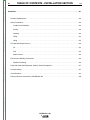
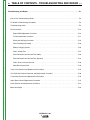
- MASTER TABLE OF CONTENTS FOR ALL SECTIONS RETURN TO MAIN MENU
Page
Safety . . . . . . . . . . . . . . . . . . . . . . . . . . . . . . . . . . . . . . . . . . . . . . . . . . . . . . . . . . . . . . . . . . . . . . . . . . .i-vi
Installation . . . . . . . . . . . . . . . . . . . . . . . . . . . . . . . . . . . . . . . . . . . . . . . . . . . . . . . . . . . . . . . . . .Section A
Operation . . . . . . . . . . . . . . . . . . . . . . . . . . . . . . . . . . . . . . . . . . . . . . . . . . . . . . . . . . . . . . . . . .Section B
Accessories . . . . . . . . . . . . . . . . . . . . . . . . . . . . . . . . . . . . . . . . . . . . . . . . . . . . . . . . . . . . . . . .Section C
Maintenance . . . . . . . . . . . . . . . . . . . . . . . . . . . . . . . . . . . . . . . . . . . . . . . . . . . . . . . . . . . . . . . .Section D
Theory of Operation . . . . . . . . . . . . . . . . . . . . . . . . . . . . . . . . . . . . . . . . . . . . . . . . . . . . . . . . . .Section E
Troubleshooting and Repair . . . . . . . . . . . . . . . . . . . . . . . . . . . . . . . . . . . . . . . . . . . . . . . . . . .Section F
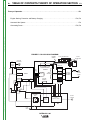
Electrical Diagrams . . . . . . . . . . . . . . . . . . . . . . . . . . . . . . . . . . . . . . . . . . . . . . . . . . . . . . . . . .Section G
Parts Manual . . . . . . . . . . . . . . . . . . . . . . . . . . . . . . . . . . . . . . . . . . . . . . . . . . . . . . . . . . . . . . . . . . .P-591
OUTBACK® 185
I
Return to Master TOC
A-1
TABLE OF CONTENTS - INSTALLATION SECTION
A-1
Installation . . . . . . . . . . . . . . . . . . . . . . . . . . . . . . . . . . . . . . . . . . . . . . . . . . . . . . . . . . . . . . . . . . . . . . . . . . . . .A-1
Technical Specifications . . . . . . . . . . . . . . . . . . . . . . . . . . . . . . . . . . . . . . . . . . . . . . . . . . . . . . . . . . . . . . . .A-2
Safety Precautions . . . . . . . . . . . . . . . . . . . . . . . . . . . . . . . . . . . . . . . . . . . . . . . . . . . . . . . . . . . . . . . . . . . .A-3
Location and Ventilation . . . . . . . . . . . . . . . . . . . . . . . . . . . . . . . . . . . . . . . . . . . . . . . . . . . . . . . . . . . . .A-3
Storing . . . . . . . . . . . . . . . . . . . . . . . . . . . . . . . . . . . . . . . . . . . . . . . . . . . . . . . . . . . . . . . . . . . . . . . . . .A-3
Return to Master TOC
Stacking . . . . . . . . . . . . . . . . . . . . . . . . . . . . . . . . . . . . . . . . . . . . . . . . . . . . . . . . . . . . . . . . . . . . . . . . .A-4
Tilting . . . . . . . . . . . . . . . . . . . . . . . . . . . . . . . . . . . . . . . . . . . . . . . . . . . . . . . . . . . . . . . . . . . . . . . . . . .A-4
Lifting . . . . . . . . . . . . . . . . . . . . . . . . . . . . . . . . . . . . . . . . . . . . . . . . . . . . . . . . . . . . . . . . . . . . . . . . . . .A-4
Pre-Operation Engine Service . . . . . . . . . . . . . . . . . . . . . . . . . . . . . . . . . . . . . . . . . . . . . . . . . . . . . . . . . . .A-4
Oil . . . . . . . . . . . . . . . . . . . . . . . . . . . . . . . . . . . . . . . . . . . . . . . . . . . . . . . . . . . . . . . . . . . . . . . . . . . . . .A-4
Fuel . . . . . . . . . . . . . . . . . . . . . . . . . . . . . . . . . . . . . . . . . . . . . . . . . . . . . . . . . . . . . . . . . . . . . . . . . . . .A-4
Spark Arrester . . . . . . . . . . . . . . . . . . . . . . . . . . . . . . . . . . . . . . . . . . . . . . . . . . . . . . . . . . . . . . . . . . . .A-4
Electrical and Welding Connections . . . . . . . . . . . . . . . . . . . . . . . . . . . . . . . . . . . . . . . . . . . . . . . . . . . . . . .A-5
Machine Grounding . . . . . . . . . . . . . . . . . . . . . . . . . . . . . . . . . . . . . . . . . . . . . . . . . . . . . . . . . . . . . . . .A-6
Premises Wiring . . . . . . . . . . . . . . . . . . . . . . . . . . . . . . . . . . . . . . . . . . . . . . . . . . . . . . . . . . . . . . . . . . . . . .A-7
Circuit Breakers . . . . . . . . . . . . . . . . . . . . . . . . . . . . . . . . . . . . . . . . . . . . . . . . . . . . . . . . . . . . . . . . . . . . . .A-7
Electrical Devices used with the OUTBACK® 185 . . . . . . . . . . . . . . . . . . . . . . . . . . . . . . . . . . . . . . . . . . .A-8
Return to Master TOC
Return to Master TOC
Plugs and Hand-Held Equipment, Auxiliary Power Receptacles . . . . . . . . . . . . . . . . . . . . . . . . . . . . . . . . .A-7
OUTBACK® 185
INSTALLATION
Return to Master TOC
Return to Section TOC
A-2
A-2
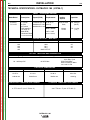
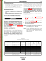
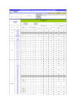
TECHNICAL SPECIFICATIONS - OUTBACK® 185 (K2706-1)
INPUT - GASOLINE ENGINE
Make/Model
Description
KOHLER
CS 12.75
Speed (RPM)
3750RPM High Idle
1 cylinder
4 cycle
1825RPM Low Idle
air-cooled
3400RPM Full Load
OHV gasoline
12.75 HP @
3600 RPM
Aluminum Block
Displacement
21.96 cu. in
(360 cc)
Ignition
System
Electric & Recoil
Start;
Bore x Stroke
Manual
Choke
Capacities
Fuel: 6.86 gal.
(24.9L)
Oil: 1.2 Qts.
(1.1L)
3.35” x 2.48”
(85 mm x 63mm)
Return to Master TOC
Return to Section TOC
w/ Cast Iron Sleeve
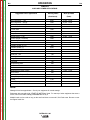
RATED OUTPUT - WELDER
AMPS @ DC CONSTANT CURRENT
DUTY CYCLE
100
130
150
185
VOLTS @ RATED AMPERES
100%
60%
20%
MAX OUTPUT
25
25
25
---
OUTPUT -WELDER AND GENERATOR
Welding Ranges
Welding Open Circuit Voltage
Return to Master TOC
Return to Section TOC
50 - 185 Amps DC
80 VDC Max.
PHYSICAL DIMENSIONS
HEIGHT
25.47 in.
646.94 mm
WIDTH
21.12 in.
536.45 mm
DEPTH
WEIGHT
31.48 in.
310.0 lbs.
799.59 mm
OPERATING TEMPERATURE RANGE
140.6 kg
STORAGE TEMPERATURE RANGE
-40° F TO 131° F (-40° C TO 55° C)
Return to Master TOC
0° F TO 104° F (-18° C TO 40° C)
Return to Section TOC
AC Auxiliary Power
4600 Watts 115V 1PH
100% Duty Cycle
5700 Peak Watts
5200 Continuous Watts
120 / 230 V 1PH
OUTBACK® 185
INSTALLATION
Return to Master TOC
Return to Master TOC
Return to Section TOC
Return to Section TOC
A-3
SAFETY PRECAUTIONS
LOCATION AND VENTILATION
Read this entire installation section before you
start installation.
WARNING
Do not attempt to use this equipment until you
have thoroughly read all operating and maintenance manuals supplied with your machine. They
include important safety precautions, detailed
engine starting, operating and maintenance
instructions, and parts lists.
Hazards of Electric Shock,
Exhaust & Moving Parts
Engine
WARNING
• Do not touch electrically live parts
or electrode with skin or wet clothing.
• Always wear dry insulating gloves.
Return to Master TOC
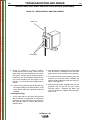
The OUTBACK® 185 must be used outdoors. Do not set
the machine in puddles or otherwise submerge it in water.
Such practices pose safety hazards and cause improper
operation and corrosion of parts.
Always operate the OUTBACK® 185 with the case roof on
and all machine components completely assembled. This will
help to protect you from the dangers of moving parts, hot
metal surfaces, and live electrical devices.
1.
2.
3.
ENGINE EXHAUST can kill.
Return to Section TOC
Whenever you use the OUTBACK® 185, be sure that clean
cooling air can flow around the machine’s gasoline engine
and the generator. Avoid dusty, dirty areas. Also, keep the
machine away from heat sources. Do not place the back end
of the generator anywhere near hot engine exhaust from
another machine. And of course, make sure that engine
exhaust is ventilated to an open, outside area.
STORING
ELECTRIC SHOCK can kill.
• Insulate yourself from work and
ground.
• Use in open, well ventilated areas
or vent exhaust outside.
• Do not stack anything on or near
the engine.
4.
5.
MOVING PARTS can injure.
• Do not operate with doors open or
guards off.
• Stop engine before servicing.
6.
• Keep away from moving parts.
7.
Store the machine in a cool, dry place when it is not in
use. Protect it from dust and dirt. Keep it where it can not
be accidentally damaged from construction activities,
moving vehicles and other hazards.
If you will be storing the machine for over 30 days, you
should drain the fuel to protect fuel system and carburetor parts from gum deposits. Empty all fuel from the tank
and run the engine until it stops from lack of fuel.
You can store the machine for up to 24 months if you use
a stabilizing Additive in the fuel system. Mix the additive
with the fuel in the tank and run the engine for a short
time to circulate the additive through the carburetor.
While the engine is still warm, drain the oil and refill with
fresh 10W30 oil.
Remove the spark plug and pour approximately 1/2
ounce (15ml) of engine oil into the cylinder. Replace the
spark plug and crank the engine slowly to distribute the
oil.
Clean any dirt and debris from the cylinder and cylinder
head fins and housing, rotating screen, and muffler
areas.
Store in a clean, dry area.
Return to Master TOC
Only qualified personnel should install, use, or
service this equipment.
Return to Section TOC
A-3
OUTBACK® 185
INSTALLATION
Return to Master TOC
Return to Master TOC
Return to Section TOC
Return to Section TOC
A-4
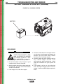
STACKING
OIL
OUTBACK® 185 machines CANNOT be stacked.
The OUTBACK® 185 is shipped with the engine filled
with SAE 10W30 oil. CHECK THE OIL LEVEL
BEFORE YOU START THE ENGINE. This is an added
precaution. Do not screw in dipstick when checking oil
level. DO NOT OVERFILL. Be sure the fill plug is tight
after servicing.
TILTING
Place the machine on a secure, level surface whenever you use it or store it. Any surfaces you place it on
other than the ground must be firm, non-skid, and
structurally sound.
FUEL
The gasoline engine is designed to run in a level position for best performance. It can operate at an angle,
but this should never be more than 15 degrees in any
direction. If you do operate it at a slight angle, be sure
to check the oil regularly and keep the oil level full.
Also, fuel capacity will be a little less at an angle.
Fill the fuel tank with clean, fresh, regular grade (minimum 87 octane lead free gasoline. DO NOT MIX OIL
WITH GAS. The OUTBACK® 185 capacity is approximately 6.8 gallons (25.74 Liter). DO NOT OVERFILL,
allow room in the fuel tank for fuel expansion.
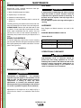
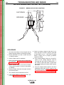
LIFTING
SPARK ARRESTER
The OUTBACK® 185 should be lifted by two people.
(See Technical Specification page for weight). The
LowLift™ grab bars on both ends make lifting easier.
Some federal, state or local laws may require gasoline
engines to be equipped with exhaust spark arresters
when they are operated in certain locations where
unarrested sparks may present a fire hazard. The
standard muffler included with this machine does not
qualify as a spark arrester. For areas requiring spark
arrestors, use K2793-1.
PRE-OPERATION ENGINE SERVICE
Return to Section TOC
Return to Master TOC
Return to Master TOC
Read and understand the engine operating and
maintenance instructions supplied with this machine
before you operate the OUTBACK® 185.
Return to Section TOC
A-4
CAUTION
An incorrect additional arrester may lead to damage to the engine or adversely affect performance.
------------------------------------------------------------------------
WARNING
• Keep hands away from muffler or HOT engine
parts.
• Stop the engine when fueling.
• Do not smoke when fueling.
• Remove fuel cap slowly to release pressure.
• Do not overfill tank.
• Wipe up spilled fuel and allow fumes to clear
before starting engine.
• Keep sparks and flame away from tank.
------------------------------------------------------------------------
OUTBACK® 185
INSTALLATION
Return to Section TOC
Return to Master TOC
Return to Section TOC
Return to Master TOC
A-5
A-5
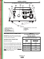
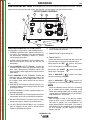
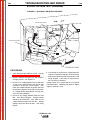
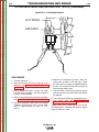
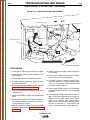
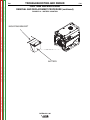
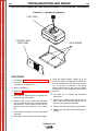
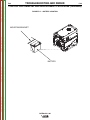
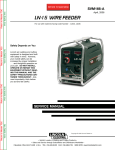
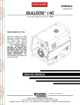
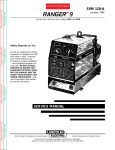
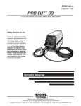
OUTBACK® 185 OUTPUT CONNECTIONS
9
1
8
4
7
5
6
10
3
2
FIGURE A.1
Return to Master TOC
Return to Section TOC
1.
2.
3.
4.
5.
6.
CURRENT CONTROL DIAL
WELD OUTPUT TERMINALS (2)
GROUND STUD
CIRCUIT BREAKERS (2) - 20 AMP
CIRCUIT BREAKER 30 Amp
RECEPTACLE - 240 VOLT, 50 AMP
7. DUPLEX RECEPTACLE (2)- 120 VOLT, 20 AMP
8. HOURMETER
9. ENGINE SWITCH
10. CHOKE
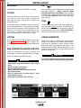
ELECTRICAL OUTPUT CONNECTIONS
See Figure A.1 for the location of the current control
dial, weld output terminals, ground stud, circuit breakers, 240 and 120 volt receptacles.
TABLE A.1
RECOMMENDED WELDING CABLE
SIZE AND LENGTH
TOTAL COMBINED LENGTH OF
ELECTRODE AND WORK CABLES
WELDING CABLE CONNECTIONS
Cable
Length
125 Amps
30% Duty Cycle
Cable Size and Length
Return to Master TOC
Return to Section TOC
Be sure to use welding cables that are large enough.
The correct size and length becomes especially important when you are welding at a distance from the welder.
Table A.1 lists recommended cable sizes and lengths for
rated current and duty cycle. Length refers to the distance from the welder to the work and back to the
welder. Cable diameters are increased for long cable
lengths to reduce voltage drops.
0-50 ft (0-15m)
6 AWG
50-100 ft (15-30 m)
5 AWG
100-150 ft (30-46 m)
3 AWG
150-200 ft (46-61 m)
2 AWG
200-250 ft (61-76m)
1 AWG
OUTBACK® 185
INSTALLATION
Cable Installation
Return to Master TOC
Return to Section TOC
A-6
MACHINE GROUNDING
Install the welding cables to your OUTBACK® 185 as
follows. See Figure A.1 for the location of parts.
1. The gasoline engine must be OFF to install welding cables.
2. Remove the 1/2-13 flanged nuts from the output
terminals.
3. Connect the electrode holder and work cables to
the weld output terminals. Normally, the electrode
cable is connected to the positive (+) output stud.
Return to Master TOC
Return to Section TOC
4. Tighten the flanged nuts securely.
5. Be certain that the metal piece you are welding
(the “work”) is securely connected to the work
clamp and cable.
6. Check and tighten the connections periodically.
CAUTION
• Loose connections will cause the output studs to
overheat and the studs may eventually melt.
• Do not cross welding cables at output stud connection. Keep isolated and separate from one another.
Return to Section TOC
Return to Master TOC
Return to Master TOC
------------------------------------------------------------------------
Return to Section TOC
A-6
Lincoln Electric offers a welding accessory kit with #6
welding cables. See the ACCESSORIES section of
this manual for more information.
Because this portable engine driven welder or generator creates its own power, it is not necessary to connect
its frame to an earth ground, unless the machine is
connected to premises wiring (your home, shop, etc.).
To prevent dangerous electric shock, other equipment
to which this engine driven welder supplies power,
must:
a) be grounded to the frame of the welder using a
grounded type plug
or
b) be double insulated
When this welder is mounted on a truck or trailer, the
machine grounding
stud must be securely connected to the metal frame of the vehicle.
In general if the machine is to be grounded, it should
be connected with a #8 or larger copper wire to a solid
earth ground such as a metal water pipe going into the
ground for at least ten feet and having no insulated
joints, or to the metal framework of a building which
has been effectively grounded. The U.S. National
Electrical Code lists a number of alternate means of
grounding electrical equipment. A machine grounding
stud marked with the symbol
is provided on the
front of the welder.
WARNING
DO NOT GROUND MACHINE TO A PIPE WHICH CARRIES EXPLOSIVE OR COMBUSTIBLE MATERIAL.
------------------------------------------------------------------------
For more information on welding , see WELDING
OPERATION in the OPERATION section of this manual.
OUTBACK® 185
INSTALLATION
Return to Master TOC
Return to Section TOC
A-7
PLUGS AND HAND HELD EQUIPMENT
PREMISES WIRING
For further protection against electric shock, any electrical equipment connected to the generator receptacles must use a three-blade, grounded type plug or an
Underwriter’s Laboratories (UL) approved double insulated tool with a two blade plug.
The OUTBACK® 185 is not recommended for premises wiring. The OUTBACK® 185 does not have a combined 120/240 volt receptacle and cannot be connected to a premises as described in other Lincoln literature.
WARNING
Return to Master TOC
Return to Section TOC
Never operate this machine with damaged or
defective cords. All electrical equipment must be
in safe operating condition.
------------------------------------------------------------------------
AUXILIARY POWER RECEPTACLES
The control panel of the OUTBACK® 185 features
three auxiliary power receptacles:
•
•
Two 20 amp,120 volt duplex (double outlet)
receptacle.
A 50 amp, 240 volt single outlet receptacle.
See Figure A.1
Return to Section TOC
Return to Master TOC
Return to Master TOC
Through these receptacles the machine can supply up
to 5700 watts surge or 5200 watts continuous of singlephase 60 Hertz AC power. The machine output voltages meet UL standards and fall within ± 10% of the
rated voltage.
Return to Section TOC
A-7
The OUTBACK® 185 is intended only for backup,
intermittent use power. Certain electrical devices cannot be powered by the OUTBACK® 185. Refer to
Table A.2 for these devices.
CIRCUIT BREAKERS
Auxiliary power is protected by circuit breakers. When
the machine is operated in high temperature environments, the breakers may tend to trip at lower loads
than normally.
CAUTION
NEVER BYPASS THE CIRCUIT BREAKERS. WITHOUT OVERLOAD PROTECTION, THE UNIT COULD
OVERHEAT AND/OR CAUSE DAMAGE TO THE
EQUIPMENT BEING USED.
------------------------------------------------------------------------
OUTBACK® 185
INSTALLATION
Return to Master TOC
Return to Master TOC
Return to Master TOC
Return to Master TOC
Return to Section TOC
Return to Section TOC
Return to Section TOC
Return to Section TOC
A-8
A-8
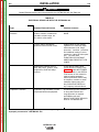
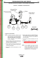
CAUTION
Certain Electrical devices cannot be powered by the OUTBACK® 185. See Table A.2
TABLE A.2
ELECTRICAL DEVICE USE WITH THE OUTBACK® 185
Type
Common Electrical Devices
Possible Concerns
Resistive
Heaters, toasters, incandescent
light bulbs, electric range, hot
pan, skillet, coffee maker.
NONE
Capacitive
TV sets, radios, microwaves,
appliances with electrical control.
Voltage spikes or high voltage
regulation can cause the capacitative elements to fail. Surge
protection, transient protection,
and additional loading is recommended for 100% fail-safe operation. DO NOT RUN
THESE DEVICES WITHOUT
ADDITIONAL RESISTIVE TYPE
LOADS.
Inductive
Single-phase induction motors,
drills, well pumps, grinders, small
refrigerators, weed and hedge
trimmers.
These devices require large
current inrush for starting. (See
Table B.3, AUXILIARY POWER
APPLICATIONS, in the OPERATION section of this manual for
required starting wattages.)
Some synchronous motors may
be frequency sensitive to attain
maximum output torque, but
they SHOULD BE SAFE from
any frequency induced failures.
Capacitive / Inductive
Computers, high resolution TV sets,
complicated electrical equipment.
An inductive type line conditioner along with transient and
surge protection is required,
and liabilities still exist.
DO NOT USE THESE DEVICES
WITH A OUTBACK® 185.
The Lincoln Electric Company is not responsible for any damage to electrical components
improperly connected to a OUTBACK® 185.
OUTBACK® 185
Return to Master TOC
B-1
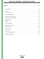
TABLE OF CONTENTS - OPERATION SECTION
B-1
Operation . . . . . . . . . . . . . . . . . . . . . . . . . . . . . . . . . . . . . . . . . . . . . . . . . . . . . . . . . . . . . . . . . . . . . . . . . . . . . .B-1
Safety Instructions . . . . . . . . . . . . . . . . . . . . . . . . . . . . . . . . . . . . . . . . . . . . . . . . . . . . . . . . . . . . . . . . . . . .B-2
Symbols . . . . . . . . . . . . . . . . . . . . . . . . . . . . . . . . . . . . . . . . . . . . . . . . . . . . . . . . . . . . . . . . . . . . . . . . . . . .B-3
General Description
. . . . . . . . . . . . . . . . . . . . . . . . . . . . . . . . . . . . . . . . . . . . . . . . . . . . . . . . . . . . . . . . . .B-4
Recommended Applications . . . . . . . . . . . . . . . . . . . . . . . . . . . . . . . . . . . . . . . . . . . . . . . . . . . . . . . . . . . .B-4
Return to Master TOC
Operational Features and Controls . . . . . . . . . . . . . . . . . . . . . . . . . . . . . . . . . . . . . . . . . . . . . . . . . . . . . . .B-4
Design Features and Advantages . . . . . . . . . . . . . . . . . . . . . . . . . . . . . . . . . . . . . . . . . . . . . . . . . . . . . . . .B-4
Welding Capability . . . . . . . . . . . . . . . . . . . . . . . . . . . . . . . . . . . . . . . . . . . . . . . . . . . . . . . . . . . . . . . . . . . .B-4
Limitations . . . . . . . . . . . . . . . . . . . . . . . . . . . . . . . . . . . . . . . . . . . . . . . . . . . . . . . . . . . . . . . . . . . . . . . . . .B-4
Controls and Settings . . . . . . . . . . . . . . . . . . . . . . . . . . . . . . . . . . . . . . . . . . . . . . . . . . . . . . . . . . . . . . . . .B-5
Welder/Generator Controls . . . . . . . . . . . . . . . . . . . . . . . . . . . . . . . . . . . . . . . . . . . . . . . . . . . . . . . . . . . . .B-5
Engine Operation
. . . . . . . . . . . . . . . . . . . . . . . . . . . . . . . . . . . . . . . . . . . . . . . . . . . . . . . . . . . . . . . . . . . .B-6
Welding Operation
. . . . . . . . . . . . . . . . . . . . . . . . . . . . . . . . . . . . . . . . . . . . . . . . . . . . . . . . . . . . . . . . . . .B-7
Auxiliary Power . . . . . . . . . . . . . . . . . . . . . . . . . . . . . . . . . . . . . . . . . . . . . . . . . . . . . . . . . . . . . . . . . . . . . .B-8
Auxiliary Power Application . . . . . . . . . . . . . . . . . . . . . . . . . . . . . . . . . . . . . . . . . . . . . . . . . . . . . . . . . . . . .B-9
Return to Master TOC
Return to Master TOC
Electrode selection Guide . . . . . . . . . . . . . . . . . . . . . . . . . . . . . . . . . . . . . . . . . . . . . . . . . . . . . . . . . . .B-8
OUTBACK® 185
OPERATION
Return to Master TOC
Return to Section TOC
B-2
SAFETY INSTRUCTIONS
WARNING
WARNING
ELECTRIC SHOCK
can kill.
ENGINE EXHAUST can kill.
• Use in open, well ventilated areas
or vent exhaust outside.
• Do not touch electrically live parts
or electrode with skin or wet
clothing.
• Do not stack anything on or near
the engine.
• Insulate yourself from work and
ground.
MOVING PARTS can injure.
• Do not operate with doors open or
guards off.
Return to Master TOC
Return to Section TOC
• Always wear dry insulating
gloves.
• Stop engine before servicing.
• Keep away from moving parts.
FUMES AND GASES
can be dangerous.
Only qualified personnel should install, use, or
service this equipment.
• Keep your head out of fumes.
• Use ventilation or exhaust to
remove fumes from breathing
zone.
Observe additional Safety Guidelines detailed
throughout this manual.
WELDING SPARKS
can cause fire or
explosion
Return to Section TOC
Return to Master TOC
Return to Master TOC
• Keep flammable material away.
Return to Section TOC
B-2
• Do not weld on containers that
have held combustibles.
ARC RAYS
can burn.
• Wear eye, ear and body
protection.
OUTBACK® 185
OPERATION
Return to Master TOC
Return to Master TOC
Return to Master TOC
Return to Master TOC
Return to Section TOC
Return to Section TOC
Return to Section TOC
Return to Section TOC
B-3
B-3
GRAPHIC SYMBOLS USED ON THIS EQUIPMENT OR IN THIS MANUAL
WARNING /
CAUTION
CHOKE
OIL
AIR CLEANER
FUEL
CIRCUIT
BREAKER
WORK CLAMP
GROUND
(AUXILIARY
POWER)
FAST
ELECTRODE
WELDING ARC
SLOW
ENGINE OFF
AUTO IDLE
OUTBACK® 185
ENGINE START
OPERATION
Return to Master TOC
Return to Section TOC
B-4
GENERAL DESCRIPTION
The OUTBACK® 185 is designed for commercial use
welder/generator applications. As a welder it provides
185 amps of DC constant current for welding with DC
stick electrodes. A single dial lets you select a full
range of welding output from 50 to 185 amps.
As a generator it can supply up to surge watts or continuous watts of 120 / 240 volt, single-phase AC power.
The machine is portable.
Return to Master TOC
Return to Section TOC
A Kohler CS 12.75 HP air cooled, OHV gasoline
engine powers the welder / generator. It has an engine
warranty of 3 years.
RECOMMENDED APPLICATIONS
Welder
The OUTBACK® 185 provides excellent constant current DC welding output for stick (SMAW) welding.
Generator
The OUTBACK® 185 gives smooth AC generator output for continuous auxiliary power usage within the
engine manufacturer’s required maintenance recommendations.
Return to Section TOC
Return to Master TOC
Return to Section TOC
Return to Master TOC
OPERATIONAL
CONTROLS
FEATURES
AND
The OUTBACK® 185 was designed for simplicity.
Therefore, it has very few operating controls. A single
dial on the control panel lets you select either welder
or generator use. For welding, the same dial selects
continuous current output over the machine’s 50 to
185 amp range.
The gasoline engine controls include a recoil starter,
choke and stop switch. See ENGINE OPERATION in
the OPERATION section of this manual for details
about starting, running, stopping, and breaking in the
gasoline engine.
B-4
DESIGN FEATURES AND
ADVANTAGES
• 185 amp DC constant current welding for stick
electrodes.
• Lightweight / portable.
• Full range, continuous welding output control with
a single knob.
• Automatic shutdown under low oil level condition.
• Hour Meter Standard.
• Surge watts or Watts of continuous 120 / 240 volt
single phase AC auxiliary power.
• Kohler CS 12.75 HP overhead cam air-cooled
gasoline engine. Smooth running, long life.
WELDING CAPABILITY
The OUTBACK® 185 rated 185 amps, 20 VDC at 10%
duty cycle on a ten-minute basis. This means that you
can load the welder to 185 amps for one minute out of
every ten-minute period. The machine is capable of
higher duty cycles at lower output currents. For example, you can load the welder to 120 amps for ten minutes out of ten for a 100% duty cycle.
The current is continuously variable from 50 to 185
amps DC. The OUTBACK® 185 can, therefore, weld
with all 3/32”, 1/8” and most 5/32” diameter Lincoln DC
electrodes.
LIMITATIONS
• The OUTBACK® 185 is not recommended for any
processes besides those that are normally performed using stick welding (SMAW) procedures.
• The OUTBACK® 185 is not recommended for pipe
thawing.
• During welding, generator power is limited to 100
watts, and output voltages can drop from 120 to 80
volts and 240 to 160 volts. Therefore, DO NOT
OPERATE ANY SENSITIVE ELECTRICAL EQUIPMENT WHILE YOU ARE WELDING.
OUTBACK® 185
OPERATION
Return to Section TOC
Return to Master TOC
Return to Section TOC
Return to Master TOC
B-5
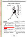
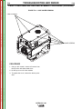
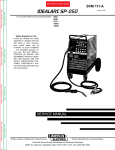
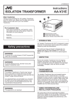
CONTROLS AND SETTINGS
All welder/generator controls are located on the Output Control Panel. Gasoline
engine controls are mounted on the engine. See Figure B.1 and the figures in engine operation section.
OUTPUT PANEL CONTROLS
12
10
1
Return to Master TOC
Return to Section TOC
7
2
11
5
6
3 or 4
WELDER/GENERATOR CONTROLS
See Figure B.1 for the location of the following features:
1. CURRENT CONTROL DIAL: Adjusts continuous current output. The amperages on the dial correspond to
the approximate amperages needed for specific
Lincoln welding electrodes.
3. WELD POSITIVE OUTPUT TERMINAL: Provides the
connection point for either the electrode holder or the
work cable. (Because the OUTBACK® 185 is a DC
output machine, either output terminal can be used for
either cable.)
4. WELD NEGATIVE OUTPUT TERMINAL: Provides the
connection point for either the electrode holder or the
work cable. (Because the OUTBACK®185 is a DC output machine, either output terminal can be used for
either cable.)
5. GROUND STUD: Provides a connection point for connecting the machine case to earth ground for the safest
grounding procedure.
6. CIRCUIT BREAKER: Provides overload protection for
weld output terminals.
Return to Master TOC
9
8
2. 30 AMP CIRCUIT BREAKER: Provide separate overload current protection for the 120 Volt and 240 Volt
Receptacles
Return to Section TOC
B-5
7. CIRCUIT BREAKERS (2): Provide separate overload current protection for the 120 volt and 240 volt receptacles
8. 240 VOLT RECEPTACLE: Connection point for supplying 250 volt power to operate one electrical device.
9. 120 VOLT DUPLEX RECEPTACLES (2): Connection
point for supplying 120 volt power to operate devices
needed for maintenance purposes.
FIGURE B.1
10. HOUR METER: Records the time that the engine has
run for maintenance purposes.
11. ENGINE CHOKE: Engine starting aid.
12. ENGINE SWITCH:
Used to start the engine, Select High Idle or Auto Idle
while the engine is running and stops the engine.
When placed in the “OFF”
position, the ignition
circuit is de-energized to shut down the engine.
When held in the “START”
starter motor is energized.
position, the engine
When in “HIGH IDLE” (
) position, the engine
will run continuously at high idle.
When in “AUTO IDLE” (
/
) position, the
engine will run continuously and the idler operates as
follows:
• Welding
When the electrode touches the work, the welding
arc is initiated and the engine accelerates to full
speed. After welding ceases (and no auxiliary power
is being drawn), the engine will return to low idle after
approximately 10 to 14 seconds.
• Auxiliary Power
With the engine running at low idle and auxiliary
power for lights or tools is drawn (approximately 0150 watts or greater) from the receptacles, the
engine will accelerate to high speed. If no power is
being drawn from the receptacles (and not welding)
for 10-14 seconds, the idler reduces the engine
speed to low idle.
OUTBACK® 185
OPERATION
Return to Master TOC
Return to Section TOC
B-6
ENGINE OPERATION
Break-in Period
Starting/Shutdown Instructions
It is normal for any engine to use larger quantities of oil
until break-in is accomplished. Check the oil level
twice a day during the break-in period (about 50 running hours). Change the oil after the first 5 hours of
operation. See the Engine Instruction Manual for further details.
Be sure all Pre-Operation Engine Service has been
performed. Also, Read owners manual before starting
for the first time. (See INSTALLATION section)
Remove all loads connected to the AC power receptacles. Before starting, first open the fuel shutoff valve.
Return to Master TOC
Always pull the choke control out when starting the
engine; cold, warm or hot.
Return to Section TOC
B-6
Turn the engine switch to the “Start”
position and
crank the engine until it starts, slowly return the choke
control to the full “in” position (choke open), and turn
the switch to the Auto Idle (
/
) position.
Do not turn the switch to the “start” position while the
engine is running because this will cause damage to
the ring gear and/or starter motor.
Stopping the Engine
Remove all welding and auxiliary power loads and
allow engine to run for a few minutes to cool the
engine.
Stop the engine by placing the engine switch in the
“Off” (
) position.
CAUTION
IN ORDER TO ACCOMPLISH THIS BREAK-IN, THE
UNIT SHOULD BE SUBJECTED TO MODERATE
LOADS, WITHIN THE RATING OF THE MACHINE.
AVOID LONG IDLE RUNNING PERIODS. REMOVE
LOADS AND ALLOW ENGINE TO COOL SEVERAL
MINUTES AT LOW IDLE BEFORE SHUTDOWN.
-----------------------------------------------------------------------
Low Oil Sensing
This engine has a built in sensor which responds to low
oil level (not pressure). When activated, the system
will shut the engine down. The engine will not restart
until sufficient oil is added. Check oil level frequently
and add oil as required to the full mark on the dipstick.
DO NOT OVERFILL.
Typical Fuel Consumption
Return to Section TOC
Return to Master TOC
Return to Section TOC
Return to Master TOC
KOHLER CS 12.75 HP
WARNING
Close the fuel valve when the machine is
transported to prevent fuel leakage from
the carburetor.
------------------------------------------------------------------------
NO LOAD.
2250 R.P.M
.20 GALLONS/HOUR
.75 ( LITERS/HOUR)
NO LOAD
3750 R.P.M.
.40 GALLONS/HOUR
1.51 ( LITERS/HOUR)
DC CC WELD OUTPUT
100 AMPS, 25 VOLTS
.73 GALLONS/HOUR
2.77 ( LITERS/HOUR)
AUXILIARY POWER
5200 KVA
.99 GALLONS/HOUR
3.74 ( LITERS/HOUR)
OUTBACK® 185
OPERATION
Return to Master TOC
Return to Section TOC
B-7
WELDING OPERATION
WARNING
ELECTRIC SHOCK can kill.
• Do not touch electrically live parts
or electrode with skin or wet clothing.
• Insulate yourself from work and
ground.
• Always wear dry insulating gloves.
ENGINE EXHAUST can kill.
Return to Master TOC
Return to Section TOC
• Use in open, well ventilated areas
or vent exhaust outside.
• Do not stack anything on or near
the engine.
MOVING PARTS can injure.
• Do not operate with doors open or
guards off.
• Stop engine before servicing.
• Keep away from moving parts.
Only qualified personnel should install, use, or
service this equipment.
Return to Master TOC
Return to Section TOC
The OUTBACK® 185 can deliver from 50 to 185
amps of welding output current . Output can be
adjusted by setting the current control dial on the output control panel.
You can get maximum welding output by setting the
dial to 185 AMPS. At high current settings like this,
some output may decrease as the machine is used.
If you are welding for a long time, you may need to
turn the dial slightly upward to maintain the same
results.
The numbers on the dial correspond to the approximate amps needed to weld using specific Lincoln
welding rods. Table B.2, WELDING APPLICATIONS,
give you the recommended dial settings based on the
thickness of the work and the size and type of rod
you’re using.
B-7
4. Insert the electrode into the electrode holder.
5. Set the current control dial to the desired output
current .
6. Start the gasoline engine.
See ENGINE OPERATION in this section of
the manual.
7. Strike an arc and begin welding.
AFTER YOU FINISH THE WELD:
Stop the gasoline engine. See ENGINE OPERATION in this section of the manual.
2. Allow the electrode and work to cool completely.
3. Remove the work clamp from the work.
4. Remove any remaining piece of electrode from the
electrode holder.
5. If you are finished using the OUTBACK® 185 for
welding, disconnect the welding cables from the weld
output terminals. Reattach the flange nuts and leave
them on the terminals.
For DC+ welding, the electrode cable is to be connected
to the “+” output stud and work cable to the “-” output
stud. (For DC- welding, reverse these connections.)
1.
Semi-automatic Wire Welding with a Lincoln Wire
Feeder/Welder
The OUTBACK® 185 generator power can be used to
supply up to 5,200 watts continuous input power to a
Lincoln Wire Feeder/Welder. The Wire Feeder/ Welder is
equipped with all the supplies needed for Flux-Cored Arc
Welding (FCAW). Also some Wire Feeder/Welders come
equipped with the essentials needed for Gas Metal Arc
Welding (GMAW) or MIG processes, while others require
the purchase of a conversion kit. These products are
available where Lincoln products are sold. Contact your
local authorized Lincoln representative for more details.
Plasma Cutting with Lincoln Pro-Cut 25.
The OUTBACK® 185 generator power can be used to
supply up to 5,200 watts continuous input power to a ProCut 25. The Pro-Cut will work satisfactorily under the following conditions:
Return to Master TOC
Return to Section TOC
TO USE THE OUTBACK® 185 FOR WELDING:
1. Remove the flange nuts from the weld output terminals and place the work and electrode welding
cables over the terminals. See Figure B.1 and
B.1a. Replace and tighten the flange nuts
securely. Be sure the connections are tight.
2.
Select the appropriate electrode. See Table B.2
3.
Attach the work clamp securely to the work you are
welding.
1. Set the Current Control on the OUTBACK® 185 to the
185 amp position. (Higher Settings may result in a
shutdown of the Pro-Cut 25.)
2. Leave the "ON/OFF" switch on the Pro-Cut "OFF"
until the OUTBACK® 185 has been started and is at
full operating speed.
OUTBACK® 185
OPERATION
120V Receptacle Operation:
Return to Master TOC
Return to Section TOC
B-8
• Set the Output Control on the Pro-Cut 25 no higher
than the 15 amp position.( Higher settings may cause
circuit breaker on the OUTBACK® 185 to trip.)
• Maximum material thickness that can be cut is 1/4".
240V Receptacle Operation:
• The Pro-Cut 25 may be used for its full range of control.
• Maximum material thickness that can be cut is 3/8".
Return to Master TOC
Return to Section TOC
WARNING
Be sure that any electrical equipment plugged into the
generator AC power receptacles can withstand a ±10%
voltage and a ±5% frequency variation. Some electronic devices cannot be powered by the OUTBACK®
185 Refer to Table A.2, ELECTRICAL DEVICE USE
WITH THE OUTBACK® 185, in the INSTALLATION
section of this manual.
Return to Master TOC
The OUTBACK® 185 is rated at 5700 Peak watts or
5200 continuous watts. It provides both 120 volt and
240 volt power. You can draw up to 20 amps from
either side of the 120 volt duplex receptacle, but not
more than 35.4 amps from both sides at once. Up to
17.7 amps can be drawn from the single 240 volt
receptacle.
AUXILIARY POWER APPLIthe wattage requirements of
of loads you can power with
sure to read the notes at the
2. Set the current control dial on the output control
panel to “MAX.” See Figure B.1.
3. Plug the load(s) into the appropriate 120 volt or
240 volt power receptacle.
NOTE: During welding, the maximum generator output for auxiliary loads is 100 watts.
NOTE: You can supply multiple loads as long as the
total load does not exceed 5700 Peak watts or
5200 continuous watts. Be sure to start the
largest loads first.
TABLE B.2
ELECTRODE SELECTION GUIDE
CURRENT RANGE (AMPS)
AWS
CLASSIFICATION
Return to Master TOC
You can use Table B.3,
CATIONS, to determine
the most common types
the OUTBACK® 185 Be
bottom of the table.
1. Start the gasoline engine. See ENGINE OPERATION in this section of the manual.
GENERAL INFORMATION
Return to Section TOC
Electrical loads in watts are calculated by multiplying
the voltage rating of the load by the number of amps it
draws. (This information is given on the load device
nameplate.) For example, a device rated 120 volts, 2
amps will need 240 watts of power (120 x 2 = 240).
TO USE THE OUTBACK® 185 AS AN AUXILIARY
POWER SUPPLY:
AUXILIARY POWER OPERATION
Return to Section TOC
B-8
ELECTRODE
POLARITY
ELECTRODE TYPE
E6010
FLEETWELD® 5P
E6011
FLEETWELD® 35
E6011
FLEETWELD® 180
E6013
FLEETWELD® 37
E7018
EXCALIBUR® 7018
E7018
JETWELD® LH-73
E708-17 & E308L-17 BLUE MAX® 308/308L AC-DC
ENi-CI
SOFTWELD® 99Ni
WEARSHIELD® ABR
DC+
DC+
DC+
DC±
DC+
DC+
DC+
DC+
DC+
SHEET THICKNESS
OUTBACK® 185
3/32 SIZE
50-75
50-75
50-80
70-95
70-100
65-85
50-80
50-80
1/8 AND
THINNER
1/8 SIZE
75-135
70-110
55-110
100-135
90-125
90-125
75-110
80-110
50-150
5/32 SIZE
90-175
80-145
105-135
145-180
125-185
130-185
95-150
100-140
50-185
1/8 AND THICKER
OPERATION
Return to Master TOC
Return to Master TOC
Return to Master TOC
Return to Section TOC
Return to Section TOC
Return to Section TOC
B-9
B-9
TABLE B.3
AUXILIARY POWER APPLICATIONS
Suggested Power Applications
*Air Compressor - 1 HP
*Air Compressor - 3/4 HP
*Airless Sprayer - 1/3 HP
Chain Saw
Circular Saw
Coffee Maker
*Deep Freezer
*Electric Motor - 1 HP
Electric Range (1 element)
Electric Skillet
*Furnace Fan - 1/3 HP
Portable Grinder (4 1/2”)
Portable Grinder (7”)
Halogen Work Light
Hand Drill - 1/4”
Hand Drill - 3/8”
1500 Watt Heater
Hedge Trimmer
Light Bulb
Reciprocating Saw
Radial Arm Saw
Radio
*Refrigerator/Freezer (small)
Slow Cooker
*Submersible Pump - 1 HP
*Sump Pump
Toaster
Weed Trimmer
Lincoln Wire Feeder/Welder
Running Watts
(Continuous)
2,000
1,250
600
1,200
1,200
1,000
500
1,000
1,500
1,250
1,200
600
2,000
500
500
700
1,750
450
100
900
2,600
50
600
200
1,000
600
1,100
500
4,000
*Start-up Watts
(Peak)
4,000 - 8,000
3,100 - 5,000
1,500 - 2,400
750 - 2,000
2,500 - 4,000
3,000 - 4,800
1,500 - 2,400
2,500 - 4,000
1,500 - 2,400
NOTES:
Wattages listed are approximate. Check your equipment for actual wattage.
Return to Master TOC
Return to Section TOC
Equipment with unusually high *START-UP WATTS are listed. For start-up of other equipment that uses a
motor, listed in the table, multiply RUNNING WATTS by 2.
Multiple loads can be used as long as the total load does not exceed 5,700 Peak watts. Be sure to start
the largest loads first.
OUTBACK® 185
Return to Section TOC
Return to Master TOC
Return to Section TOC
Return to Master TOC
Return to Master TOC
Return to Section TOC
Return to Master TOC
Return to Section TOC
B-10
NOTES
OUTBACK® 185
B-10
TABLE OF CONTENTS - ACCESSORIES SECTION
C-1
Accessories . . . . . . . . . . . . . . . . . . . . . . . . . . . . . . . . . . . . . . . . . . . . . . . . . . . . . . . . . . . . . . . . . . . . . . . . . . . .C-1
Options / Accessories . . . . . . . . . . . . . . . . . . . . . . . . . . . . . . . . . . . . . . . . . . . . . . . . . . . . . . . . . . . . . . . . .C-2
Return to Master TOC
Return to Master TOC
Return to Master TOC
Return to Master TOC
C-1
OUTBACK® 185
Return to Master TOC
Return to Master TOC
Return to Section TOC
Return to Section TOC
C-2
ACCESSORIES
OPTIONS/ACCESSORIES
The following options/accessories are available for
your OUTBACK®185 from your local Lincoln
Distributor:
Accessory Kit (K875) – Includes the following:
• Twenty feet (6.1 meters) of #6 AWG electrode cable
with lug.
• Fifteen feet (4.6 meters) of #6 work cable with lugs.
• Work Clamp
• Headshield with No. 10 filter
• Insulated electrode holder and sample electrodes
150 amp capacity.
Undercarriage (K2722-1) - A two-wheeled, hand movable undercarriage is available for field installation.
Rotor Removal Kit (S20925) - A service kit with thru
bolt and impact bolt’s for removing the generator rotor
from tapered engine crank shaft.
Spark Arrestor Kit (K2793-1) - Attaches to muffler
exhaust tube. Virtually eliminates spark emissions.
Return to Section TOC
Return to Master TOC
Return to Section TOC
Return to Master TOC
Canvas Covers (K2804-1) - To protect the Outback®
185 when not in use. Made from attractive red canvas
which is flame retardant, mildew resistant and water
repellent.
OUTBACK® 185
C-2
Return to Master TOC
D-1
TABLE OF CONTENTS - MAINTENANCE SECTION
D-1
Maintenance . . . . . . . . . . . . . . . . . . . . . . . . . . . . . . . . . . . . . . . . . . . . . . . . . . . . . . . . . . . . . . . . . . . . . . . . . . .D-1
Service Instructions . . . . . . . . . . . . . . . . . . . . . . . . . . . . . . . . . . . . . . . . . . . . . . . . . . . . . . . . . . . . . . . . . . .D-2
Safety Precautions . . . . . . . . . . . . . . . . . . . . . . . . . . . . . . . . . . . . . . . . . . . . . . . . . . . . . . . . . . . . . . . . . . . .D-3
Routine and Periodic Maintenance . . . . . . . . . . . . . . . . . . . . . . . . . . . . . . . . . . . . . . . . . . . . . . . . . . . . . . .D-3
Engine Adjustments . . . . . . . . . . . . . . . . . . . . . . . . . . . . . . . . . . . . . . . . . . . . . . . . . . . . . . . . . . . . . . . . . . .D-4
Engine Maintenance Parts . . . . . . . . . . . . . . . . . . . . . . . . . . . . . . . . . . . . . . . . . . . . . . . . . . . . . . . . . . . . . .D-4
Operational Clearance . . . . . . . . . . . . . . . . . . . . . . . . . . . . . . . . . . . . . . . . . . . . . . . . . . . . . . . . . . . . . . . . .D-4
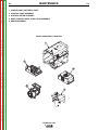
Major Component Locationss . . . . . . . . . . . . . . . . . . . . . . . . . . . . . . . . . . . . . . . . . . . . . . . . . . . . . . . . . . .D-5
Return to Master TOC
Return to Master TOC
Return to Master TOC
Slip Rings . . . . . . . . . . . . . . . . . . . . . . . . . . . . . . . . . . . . . . . . . . . . . . . . . . . . . . . . . . . . . . . . . . . . . . . . . . .D-4
OUTBACK® 185
Return to Section TOC
Return to Master TOC
Return to Section TOC
Return to Master TOC
Return to Master TOC
Return to Section TOC
Return to Master TOC
Return to Section TOC
D-2
MAINTENANCE
OUTBACK® 185
D-2
MAINTENANCE
Return to Master TOC
Return to Section TOC
D-3
SAFETY PRECAUTIONS
WARNING
• Have qualified personnel do all maintenance and
troubleshooting work.
• Turn the engine off before working inside the
machine.
Return to Master TOC
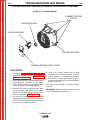
• If guards are missing from the machine, get replacements from a Lincoln Distributor. See the EXPLODED VIEW AND PARTS LIST at the back of this manual.
OIL: Check the oil level after every 5
hours of operation or daily. BE SURE
TO MAINTAIN THE OIL LEVEL.
Change the oil the first time after 20 hours of operation. Then, under normal operating conditions, change
the oil after every 100 hours or once a year, whichever occurs first. If the engine is operated under heavy
load or in high ambient temperatures, change the oil
every 50 hours.
Drain the oil from the drain plug located on either side
of the engine bottom, as shown in Figure D.1. Refill
through the oil fill plug until the oil reaches the full mark
on the dip stick. See Engine Owner’s manual for specific oil recommendations.
FIGURE D.1 - OIL DRAIN AND
REFILL LOCATION
-----------------------------------------------------------------------Read the Safety Precautions in the front of this manual and in the Kohler Operating and Maintenance
Instructions manual before working on the OUTBACK®185 Keep all equipment safety guards, covers,
and devices in position and in good repair. Keep your
hands, hair, clothing, and tools away from the recoil
housing, fans, and all other moving parts when starting, operating, or repairing this machine.
OIL
Return to Section TOC
• Remove guards only when necessary to perform
maintenance and replace them when the maintenance requiring their removal is complete.
D-3
Do not screw in
FILL to FULL mark on
dipstick to check oil
dipstick - recheck
ROUTINE AND PERIODIC
MAINTENANCE
Return to Master TOC
Return to Master TOC
Return to Section TOC
Return to Section TOC
ENGINE MAINTENANCE
12 mm
HEX
CAUTION
To prevent the engine from accidentally starting, disconnect the spark plug lead before servicing the
engine.
-----------------------------------------------------------------------See the Kohler Owner’s manual for a summary of
maintenance intervals for the engine. Follow either the
hourly or the calendar intervals, whichever come first.
More frequent service may be required, depending on
your specific application and operating conditions. The
Kohler Owner’s manual shows engine maintenance
replacement parts and numbers.
Drain
plug
OIL DRAIN
PLUG
Tighten dipstick
firmly before starting
Oil drain
FUEL: At the end of each day’s use, refill
the fuel tank to minimize moisture condensation and dirt contamination in the fuel
line.
AIR CLEANER: With normal operating
conditions, the maintenance schedule for
cleaning and re-oiling the foam pre-filter is
every 50 hours and replacement of the air
cleaner filter element every 100 hours.
More frequent servicing is required with dusty operating conditions. Refer to the maintenance section of the
Engine Owner’s Manual for more information.
OUTBACK® 185
MAINTENANCE
Return to Master TOC
Return to Section TOC
D-4
To service the pre-cleaner:
SLIP RINGS
Remove the cover. Carefully remove the foam precleaner from the filter element.
1. Wash in liquid detergent and water.
2. Squeeze dry in a clean cloth.
3. Saturate in clean engine oil.
4. Squeeze in a clean, absorbent cloth to remove all
excess oil.
Return to Master TOC
Carefully place the pre-cleaner back over the filter element and reinstall the air cleaner cover and wing nuts.
Return to Section TOC
D-4
CLEAN ENGINE: Remove dirt and debris with a cloth
or a brush. Do not clean with a forceful spray of water.
Water might contaminate the fuel system. Use low
pressure air to blow out the machine periodically. In
particularly dirty locations this may be required once a
week.
SPARK PLUG SERVICE
To service spark plug, remove the 9 screws securing
the side panel. Remove side panel and place provided
fiber spacer between the muffler and bottom of control
panel. See Figure D.2.
CAUTION
A slight amount of darkening and wear of the slip
rings and brushes is normal. Brushes should be
inspected when a general overhaul is necessary. If
brushes are to be replace, clean slip rings with a
fine emery paper.
Do not attempt to polish slip rings while engine is
running.
-----------------------------------------------------------------------
HARDWARE
Both English and Metric fasteners are used in this
welder.
ENGINE MAINTENANCE PARTS
Kohler CS 12.75
Air Filter Element
Air Filter Pre-Cleaner
Spark Plug
(Resistor Type)
63 083 19-S
63 083 17-S
Champion RC 12YC
(Gap .030” [.76mm])
FIGURE D.2
OPERATIONAL CLEARANCE
Return to Master TOC
Return to Master TOC
Return to Section TOC
Return to Section TOC
CAUTION
Approximately 12-18” of clearance should be
around this unit during operation for air flow.
Reducing this clearance will reduce air flow to the
machine causing operational temperatures to
increase. Possible damage to the machine can
result if to much air flow is restricted.
------------------------------------------------------------------------
ENGINE ADJUSTMENTS
WARNING
OVERSPEED IS HAZARDOUS - The maximum
allowable high idle speed for this machine is 3750
RPM, no load. Do NOT tamper with the governor
components or setting or make any other
adjustments to increase the maximum speed.
Severe personal injury and damage to the machine
can result if operated at speeds above maximum.
-----------------------------------------------------------------------Adjustments to the engine are to be made only by a
Lincoln Service Center or an authorize Field Service
Shop.
OUTBACK® 185
MAINTENANCE
Return to Master TOC
Return to Section TOC
D-5
D-5
1. CRADLE ASBLY, BATTERY & ROOF
2. CONTROL PANEL ASSEMBLY
3. STATOR & ROTOR ASSEMBLY
4. REAR CONTROL PANEL & FUEL TANK ASSEMBLY
5. ENGINE ASSEMBLY
Return to Master TOC
Return to Section TOC
MAJOR COMPONENT LOCATION
1
2
Return to Section TOC
Return to Master TOC
Return to Section TOC
Return to Master TOC
4
3
5
OUTBACK® 185
Return to Section TOC
Return to Master TOC
Return to Section TOC
Return to Master TOC
Return to Master TOC
Return to Section TOC
Return to Master TOC
Return to Section TOC
D-6
NOTES
OUTBACK® 185
D-6
TABLE OF CONTENTS-THEORY OF OPERATION SECTION
Return to Master TOC
E-1
E-1
Theory of Operation . . . . . . . . . . . . . . . . . . . . . . . . . . . . . . . . . . . . . . . . . . . . . . . . . . . . . . . . . . . . . . . . . . . . .E-1
Engine Starting, Protection and Battery Charging . . . . . . . . . . . . . . . . . . . . . . . . . . . . . . . . . . . . . . . .E-2, E-3
Automatic Idle System . . . . . . . . . . . . . . . . . . . . . . . . . . . . . . . . . . . . . . . . . . . . . . . . . . . . . . . . . . . . . . . . .E-4
Return to Master TOC
Generating Power . . . . . . . . . . . . . . . . . . . . . . . . . . . . . . . . . . . . . . . . . . . . . . . . . . . . . . . . . . . . . . . . .E-5, E-6
FIGURE E.1 BLOCK LOGIC DIAGRAM
CURRENT
SENSOR
OIL
LEVEL
MODULE
(KOHLER)
OIL LEVEL
INDICATOR
240 VAC
RECEPTACLE
CB1
CB3
CB4
CB2
REACTOR
OIL LEVEL
SWITCH
Return to Master TOC
120 VAC RECEPTACLES
AUXIIARY WINDINGS
STATOR
SLIP
RINGS
_
+
IGNITION
ROTOR
ENGINE
OUTPUT
RECTIFIER
(2 PHASE)
WELD
WINDINGS
CHOKE
BRUSHES
STARTER /
SOLENOID
ALTERNATOR
EXCITER
WINDING
IDLE
SOLENOID
BOOST
WINDING
10 AMP
FUSE
OFF
AUTO
_
+
HIGH
START
Return to Master TOC
BATTERY
ENGINE
SHUTDOWN
RELAY
AUTOMATIC
IDLER
CIRCUIT
HOUR
METER
OUTPUT
CONTROL CIRCUIT
FIELD / CONTROL PC BOARD
OUTBACK® 185
OUTPUT
CONTROL
+
OUTPUT
STUDS
THEORY OF OPERATION
Return to Master TOC
Return to Section TOC
E-2
E-2
FIGURE E.2 - ENGINE STARTING, PROTECTION AND BATTERY CHARGING
CURRENT
SENSOR
OIL
LEVEL
MODULE
(KOHLER)
120 VAC RECEPTACLES
OIL LEVEL
INDICATOR
240 VAC
RECEPTACLE
CB1
CB3
CB4
CB2
REACTOR
OIL LEVEL
SWITCH
AUXIIARY WINDINGS
STATOR
SLIP
RINGS
_
+
IGNITION
ROTOR
ENGINE
OUTPUT
RECTIFIER
(2 PHASE)
WELD
WINDINGS
CHOKE
+
OUTPUT
STUDS
BRUSHES
STARTER /
SOLENOID
ALTERNATOR
EXCITER
WINDING
IDLE
SOLENOID
BOOST
WINDING
10 AMP
FUSE
Return to Master TOC
Return to Section TOC
OFF
AUTO
_
+
HIGH
START
BATTERY
ENGINE
SHUTDOWN
RELAY
AUTOMATIC
IDLER
CIRCUIT
HOUR
METER
Return to Master TOC
Return to Section TOC
ENGINE STARTING
A 12 Volt battery supplies power to the rotary
run/stop/idle switch through a fuse that is located
inside the control box. There is also a lead running
from the fuse to the PC board. This is for battery
charging only.
When the switch is placed in the “Low Idle” or “High
Idle” position, a relay on the PC board is activated.
This relay activates the engine ignition system by
opening a ground lead from the engine magneto.
When the switch is held in the “Start” position, the
starter motor solenoid is activated, cranking the
engine. After the engine starts, the switch is released
and returns to the “high idle” position.
Return to Master TOC
OUTPUT
CONTROL
FIELD / CONTROL PC BOARD
ENGINE STARTING, PROTECTION
AND BATTERY CHARGING
Return to Section TOC
OUTPUT
CONTROL CIRCUIT
If the battery is too low to properly power the starter
motor, the built-in recoil starter can be used to crank
the engine. (As long as the battery can produce 6 volts
or more, the engine ignition system will remain
enabled.)
NOTE: This machine will only start if there is at least 6
volts available to activate the engine ignition system. If
the battery is removed or completely dead, the engine
will not start.
ENGINE PROTECTION
The Kohler engine has a built-in oil level sensor that is
connected to an oil level module. If the oil level is low,
the ignition magneto is disabled. This will prevent the
engine from starting, or shut it down. Low oil level will
also cause a warning light on the Outback®’s control
panel to flicker for a few seconds when cranking the
engine.
NOTE: Unshaded areas of Block Logic
Diagram are the subject of discussion
OUTBACK® 185
THEORY OF OPERATION
Return to Master TOC
Return to Section TOC
E-3
E-3
FIGURE E.3 - ENGINE STARTING, PROTECTION AND BATTERY CHARGING
CURRENT
SENSOR
OIL
LEVEL
MODULE
(KOHLER)
120 VAC RECEPTACLES
OIL LEVEL
INDICATOR
240 VAC
RECEPTACLE
CB1
CB3
CB4
CB2
REACTOR
OIL LEVEL
SWITCH
AUXIIARY WINDINGS
STATOR
SLIP
RINGS
_
+
IGNITION
ROTOR
ENGINE
OUTPUT
RECTIFIER
(2 PHASE)
WELD
WINDINGS
CHOKE
+
OUTPUT
STUDS
BRUSHES
STARTER /
SOLENOID
ALTERNATOR
EXCITER
WINDING
IDLE
SOLENOID
BOOST
WINDING
10 AMP
FUSE
Return to Master TOC
Return to Section TOC
OFF
AUTO
_
+
HIGH
START
BATTERY
ENGINE
SHUTDOWN
RELAY
AUTOMATIC
IDLER
CIRCUIT
HOUR
METER
Return to Section TOC
Return to Master TOC
Return to Master TOC
OUTPUT
CONTROL
FIELD / CONTROL PC BOARD
ENGINE STARTING, PROTECTION
AND BATTERY CHARGING (continued)
Return to Section TOC
OUTPUT
CONTROL CIRCUIT
BATTERY CHARGING
The Kohler engine has a built-in battery charging system. Output from the charging system is applied to the
PC board where it is stabilized by the battery and then
used to power the board electronics, the generator
flashing system, and the hour meter. The remaining
output exits the PC board, is routed through a fuse
located inside the control box, and applied to the battery.
NOTE: The engine charging system must be functional for the Outback® 185 to produce weld or auxiliary
output.
NOTE: The battery must remain connected at all times.
If the battery is disconnected while the machine is running, unstable voltage from the charging system will
likely cause the PC board electronics to malfunction
and may cause permanent damage to the PC board.
NOTE: Unshaded areas of Block Logic
Diagram are the subject of discussion
OUTBACK® 185
THEORY OF OPERATION
Return to Master TOC
Return to Section TOC
E-4
E-4
FIGURE E.4 - AUTOMATIC IDLE SYSTEM
CURRENT
SENSOR
OIL
LEVEL
MODULE
(KOHLER)
120 VAC RECEPTACLES
OIL LEVEL
INDICATOR
240 VAC
RECEPTACLE
CB1
CB3
CB4
CB2
REACTOR
OIL LEVEL
SWITCH
AUXIIARY WINDINGS
STATOR
SLIP
RINGS
_
+
IGNITION
ROTOR
ENGINE
OUTPUT
RECTIFIER
(2 PHASE)
WELD
WINDINGS
CHOKE
+
OUTPUT
STUDS
BRUSHES
STARTER /
SOLENOID
ALTERNATOR
EXCITER
WINDING
IDLE
SOLENOID
BOOST
WINDING
10 AMP
FUSE
Return to Master TOC
Return to Section TOC
OFF
AUTO
_
+
HIGH
START
BATTERY
ENGINE
SHUTDOWN
RELAY
AUTOMATIC
IDLER
CIRCUIT
HOUR
METER
Return to Master TOC
The Outback® 185 is equipped with an automatic
engine idle system. A solenoid is used to pull the
engine throttle to a preset low speed position when 12
volts DC is applied. When no voltage is applied, the
solenoid is released allowing the engine governor to
control the RPM.
The “high” and “auto” positions on the rotary
run/stop/idle switch control the supply of positive (+)
battery voltage to the idle solenoid. When the switch is
in the “high” position, the solenoid is shut off and the
engine will remain in high idle. When the switch is in
the “auto” position, positive (+) battery voltage is
applied to the solenoid and the negative (-) connection
is controlled by the PC board as described below.
Weld and auxiliary current are detected by a toroidal
current sensor that is connected to the PC board.
When sufficient current flows through the sensor; the
PC board detects this and immediately interrupts the
negative (-) connection to the solenoid. The solenoid
is released and the engine RPM increases to the high
setting. When the current flow stops, the PC board will
begin a time delay of about 12 seconds. If the current
flow begins again during this time delay, the solenoid
remains inactive and the engine continues to operate
at high RPM. If no current flow is detected at the end
of the 12 second delay, the negative (-) connection to
the solenoid is restored and the engine will drop to low
idle RPM.
Return to Master TOC
The following explanation assumes that the rotary
switch is in the “auto” position and the engine is operating at low RPM.
Return to Section TOC
OUTPUT
CONTROL
FIELD / CONTROL PC BOARD
AUTOMATIC IDLE SYSTEM
Return to Section TOC
OUTPUT
CONTROL CIRCUIT
NOTE: Unshaded areas of Block Logic
Diagram are the subject of discussion
OUTBACK® 185
THEORY OF OPERATION
Return to Master TOC
Return to Section TOC
E-5
E-5
FIGURE E.5 - GENERATING POWER
CURRENT
SENSOR
OIL
LEVEL
MODULE
(KOHLER)
120 VAC RECEPTACLES
OIL LEVEL
INDICATOR
240 VAC
RECEPTACLE
CB1
CB3
CB4
CB2
REACTOR
OIL LEVEL
SWITCH
AUXIIARY WINDINGS
STATOR
SLIP
RINGS
_
+
IGNITION
ROTOR
ENGINE
OUTPUT
RECTIFIER
(2 PHASE)
WELD
WINDINGS
CHOKE
+
OUTPUT
STUDS
BRUSHES
STARTER /
SOLENOID
ALTERNATOR
EXCITER
WINDING
IDLE
SOLENOID
BOOST
WINDING
10 AMP
FUSE
Return to Master TOC
Return to Section TOC
OFF
AUTO
_
+
HIGH
START
BATTERY
ENGINE
SHUTDOWN
RELAY
AUTOMATIC
IDLER
CIRCUIT
HOUR
METER
Return to Master TOC
Return to Master TOC
Return to Section TOC
OUTPUT
CONTROL
FIELD / CONTROL PC BOARD
GENERATING POWER
Return to Section TOC
OUTPUT
CONTROL CIRCUIT
Flashing
When the engine is running, power from the engine
charging system is stabilized, and then applied to the
rotor brushes through a series of PC board mounted
current limiting resistors and a “flashing” diode.
Building Output
The flashing current produces a weak magnetic field in
the rotor, which is coupled to the now running engine.
This rotating magnetic field begins to generate AC output from all of the stator windings. Output from the
exciter winding is rectified by a diode bridge, filtered by
a capacitor, controlled by circuitry on the PC board,
and fed back into the rotating field winding, making the
magnetic field stronger. This stronger magnetic field
then produces higher voltage from the stator windings,
which feeds back to the rotor, making its magnetic field
even stronger.
“high” position, all of the windings should be putting out
maximum voltage almost immediately. The rotor field
voltage is now considerably higher than the flashing
voltage that was used to start the generating process.
The “flashing” diode on the control PC board blocks
that higher field voltage from intruding into the 12VDC
battery system.
AC Output
The generator is now producing normal AC power from
all four of the windings. These windings consist of two
64 VAC weld windings, a 120/240 VAC auxiliary power
winding, and an 82 VAC excitation winding.
This process of strengthening the magnetic field
through feedback from the exciter winding continues to
increase the output of the main generator. If the output
control is set to maximum and the idle switch is in the
NOTE: Unshaded areas of Block Logic
Diagram are the subject of discussion
OUTBACK® 185
THEORY OF OPERATION
Return to Master TOC
Return to Section TOC
E-6
E-6
FIGURE E.6 - GENERATING POWER
CURRENT
SENSOR
OIL
LEVEL
MODULE
(KOHLER)
120 VAC RECEPTACLES
OIL LEVEL
INDICATOR
240 VAC
RECEPTACLE
CB1
CB3
CB4
CB2
REACTOR
OIL LEVEL
SWITCH
AUXIIARY WINDINGS
STATOR
SLIP
RINGS
_
+
IGNITION
ROTOR
ENGINE
OUTPUT
RECTIFIER
(2 PHASE)
WELD
WINDINGS
CHOKE
+
OUTPUT
STUDS
BRUSHES
STARTER /
SOLENOID
ALTERNATOR
EXCITER
WINDING
IDLE
SOLENOID
BOOST
WINDING
10 AMP
FUSE
Return to Master TOC
Return to Section TOC
OFF
AUTO
_
+
HIGH
START
BATTERY
ENGINE
SHUTDOWN
RELAY
AUTOMATIC
IDLER
CIRCUIT
HOUR
METER
OUTPUT
CONTROL CIRCUIT
OUTPUT
CONTROL
FIELD / CONTROL PC BOARD
Return to Master TOC
Return to Section TOC
GENERATING POWER
(continued)
DC Weld Output
AC output from the two phase-shifted weld windings
pass through a reactor then to a two-phase bridge rectifier. DC output from the rectifier is then stabilized by
a choke and terminates at two weld output terminals.
Weld Output Control
Weld output is controlled by varying the current in the
rotating field winding. This is done through circuitry on
the PC board that detects the position of the output
control potentiometer and then limits the rotor current
accordingly.
Weld Boost:
The Outback® 185 is equipped with a weld boost circuit that improves weld performance. The reactor contains a weld boost winding that produces output relative to the weld current. In high welding load situations,
the exciter winding will tend to drop off in output while
the boost winding’s output tends to increase. The output from this boost winding is routed through a circuit
breaker. It is then rectified and added to the exciter circuit, resulting in a significant improvement in weld performance.
Return to Master TOC
Return to Section TOC
NOTE: Because the strength of the rotating field
affects the output of all the windings, auxiliary output
will also drop when the weld output control setting is
decreased.
NOTE: Unshaded areas of Block Logic
Diagram are the subject of discussion
OUTBACK® 185
Return to Master TOC
F-1
TABLE OF CONTENTS - TROUBLESHOOTING AND REPAIR
F-1
Troubleshooting and Repair . . . . . . . . . . . . . . . . . . . . . . . . . . . . . . . . . . . . . . . . . . . . . . . . . . . . . . . . . . . . . .F-1
How to Use Troubleshooting Guide . . . . . . . . . . . . . . . . . . . . . . . . . . . . . . . . . . . . . . . . . . . . . . . . . . . . . . .F-2
PC Board Troubleshooting Procedures . . . . . . . . . . . . . . . . . . . . . . . . . . . . . . . . . . . . . . . . . . . . . . . . . . . .F-3
Troubleshooting Guide . . . . . . . . . . . . . . . . . . . . . . . . . . . . . . . . . . . . . . . . . . . . . . . . . . . . . . . . . . . . . . . . .F-4
Test Procedures . . . . . . . . . . . . . . . . . . . . . . . . . . . . . . . . . . . . . . . . . . . . . . . . . . . . . . . . . . . . . . . . . . . . .F-13
Return to Master TOC
Engine RPM Adjustment Procedure . . . . . . . . . . . . . . . . . . . . . . . . . . . . . . . . . . . . . . . . . . . . . . . . . .F-13
Throttle Adjustment Procedure . . . . . . . . . . . . . . . . . . . . . . . . . . . . . . . . . . . . . . . . . . . . . . . . . . . . . .F-17
Brush and Slip Ring Procedure
. . . . . . . . . . . . . . . . . . . . . . . . . . . . . . . . . . . . . . . . . . . . . . . . . . . . .F-19
Rotor Flashing and Voltage . . . . . . . . . . . . . . . . . . . . . . . . . . . . . . . . . . . . . . . . . . . . . . . . . . . . . . . . .F-23
Battery Charging System . . . . . . . . . . . . . . . . . . . . . . . . . . . . . . . . . . . . . . . . . . . . . . . . . . . . . . . . . . F-25
Stator Voltage Test . . . . . . . . . . . . . . . . . . . . . . . . . . . . . . . . . . . . . . . . . . . . . . . . . . . . . . . . . . . . . . .F-27
Rotor Resistance and Ground Test (Static) . . . . . . . . . . . . . . . . . . . . . . . . . . . . . . . . . . . . . . . . . . . . .F-29
Rotor Resistance and Ground Test (Dynamic) . . . . . . . . . . . . . . . . . . . . . . . . . . . . . . . . . . . . . . . . . .F-31
Stator Short Circuit and Ground . . . . . . . . . . . . . . . . . . . . . . . . . . . . . . . . . . . . . . . . . . . . . . . . . . . . .F-33
Return to Master TOC
Weld Boost System Test . . . . . . . . . . . . . . . . . . . . . . . . . . . . . . . . . . . . . . . . . . . . . . . . . . . . . . . . . . .F-35
Case Cover Removal and Replacement Procedure . . . . . . . . . . . . . . . . . . . . . . . . . . . . . . . . . . . . . . . . .F-37
Fuel Tank and Enclosure Removal and Replacement Procedure
. . . . . . . . . . . . . . . . . . . . . . . . . . . . . .F-39
Control Box Removal and Replacement Procedure . . . . . . . . . . . . . . . . . . . . . . . . . . . . . . . . . . . . . . . . .F-43
Stator Removal and Replacement Procedure . . . . . . . . . . . . . . . . . . . . . . . . . . . . . . . . . . . . . . . . . . . . . .F-47
Rotor Removal and Replacement Procedure . . . . . . . . . . . . . . . . . . . . . . . . . . . . . . . . . . . . . . . . . . . . . .F-51
Return to Master TOC
Retest and Repair . . . . . . . . . . . . . . . . . . . . . . . . . . . . . . . . . . . . . . . . . . . . . . . . . . . . . . . . . . . . . . . . . . . .F-53
OUTBACK® 185
Return to Master TOC
Return to Section TOC
F-2
TROUBLESHOOTING AND REPAIR
HOW TO USE TROUBLESHOOTING GUIDE
WARNING
Service and Repair should only be performed by Lincoln Electric Factory Trained
Personnel. Unauthorized repairs performed on this equipment may result in danger to
the technician and machine operator and will invalidate your factory warranty. For your
safety and to avoid Electrical Shock, please observe all safety notes and precautions
detailed throughout this manual.
---------------------------------------------------------------------------------------------------------------------------
Return to Section TOC
Return to Master TOC
Return to Section TOC
Return to Master TOC
Return to Section TOC
Return to Master TOC
This Troubleshooting Guide is provided to
help you locate and repair possible machine
malfunctions. Simply follow the three-step
procedure listed below.
Step 1. LOCATE PROBLEM (SYMPTOM).
Look under the column labeled “PROBLEM
(SYMPTOMS)”. This column describes possible symptoms that the machine may exhibit. Find the listing that best describes the
symptom that the machine is exhibiting.
Symptoms are grouped into the following
categories: output problems.
Step 2. PERFORM EXTERNAL TESTS.
The second column labeled “POSSIBLE
AREAS OF MISADJUSTMENT(S)” lists the
obvious external possibilities that may contribute to the machine symptom. Perform
these tests/checks in the order listed. In
general, these tests can be conducted without removing the case wrap-around cover.
Step 3. RECOMMENDED
COURSE OF ACTION
The last column labeled “Recommended
Course of Action” lists the most likely components that may have failed in your
machine. It also specifies the appropriate
test procedure to verify that the subject component is either good or bad. If there are a
number of possible components, check the
components in the order listed to eliminate
one possibility at a time until you locate the
cause of your problem.
All of the referenced test procedures
referred to in the Troubleshooting Guide are
described in detail at the end of this chapter.
Refer to the Troubleshooting and Repair
Table of Contents to locate each specific
Test Procedure. All of the specified test
points, components, terminal strips, etc. can
be found on the referenced electrical wiring
diagrams and schematics. Refer to the
Electrical Diagrams Section Table of
Contents to locate the appropriate diagram.
CAUTION
If for any reason you do not understand the test procedures or are unable to perform the
tests/repairs safely, contact the Lincoln Electric Service Department for technical troubleshooting
assistance before you proceed. Call 1-888-935-3877.
-----------------------------------------------------------------------------------------------------------------------------------
OUTBACK® 185
F-2
Return to Master TOC
Return to Section TOC
F-3
TROUBLESHOOTING AND REPAIR
PC BOARD TROUBLESHOOTING PROCEDURES
WARNING
ELECTRIC SHOCK
can kill.
• Have an electrician install and
service this equipment. Turn the
input power OFF at the fuse box
before working on equipment. Do
not touch electrically hot parts.
Return to Master TOC
Return to Section TOC
CAUTION
Sometimes machine failures appear to be due to PC
board failures. These problems can sometimes be
traced to poor electrical connections. To avoid problems when troubleshooting and replacing PC boards,
please use the following procedure:
1. Determine to the best of your technical ability
that the PC board is the most likely component
causing the failure symptom.
2. Check for loose connections at the PC board
to assure that the PC board is properly
connected.
Return to Master TOC
Return to Master TOC
Return to Section TOC
3. If the problem persists, replace the suspect PC
board using standard practices to avoid static
electrical damage and electrical shock. Read
the warning inside the static resistant bag and
perform the following procedures:
Return to Section TOC
F-3
PC board can be damaged by static electricity.
- Remove your body’s static
charge before opening the staticshielding bag. Wear an anti-static
wrist strap. For safety, use a 1
Meg ohm resistive cord connected
to a grounded part of the
ATTENTION
Static-Sensitive equipment frame.
Devices
- If you don’t have a wrist strap,
Handle only at touch an un-painted, grounded,
Static-Safe
part of the equipment frame. Keep
Workstations
touching the frame to prevent
- Remove the PC board from the static-shielding bag
and place it directly into the equipment. Don’t set the
PC board on or near paper, plastic or cloth which
could have a static charge. If the PC board can’t be
installed immediately, put it back in the static-shielding bag.
- If the PC board uses protective shorting jumpers,
don’t remove them until installation is complete.
- If you return a PC board to The Lincoln Electric
Company for credit, it must be in the static-shielding
bag. This will prevent further damage and allow proper failure analysis.
4. Test the machine to determine if the failure
symptom has been corrected by the
replacement PC board.
NOTE: It is desirable to have a spare (known good)
PC board available for PC board troubleshooting.
NOTE: Allow the machine to heat up so that all
electrical components can reach their operating
temperature.
5. Remove the replacement PC board and
substitute it with the original PC board to
recreate the original problem.
a. If the original problem does not reappear by
substituting the original board, then the PC
board was not the problem. Continue to look
for bad connections in the control wiring
harness, junction blocks, and terminal strips.
b. If the original problem is recreated by the
substitution of the original board, then the PC
board was the problem. Reinstall the
replacement PC board and test the machine.
6. Always indicate that this procedure was
followed when warranty reports are to be
submitted.
NOTE: Following this procedure and writing on the
warranty report, “INSTALLED AND SWITCHED PC
BOARDS TO VERIFY PROBLEM,” will help avoid
denial of legitimate PC board warranty claims.
static build-up. Be sure not to
touch any electrically live parts at
the same time.
- Tools which come in contact with the PC board must
be either conductive, anti-static or static-dissipative.
OUTBACK® 185
TROUBLESHOOTING AND REPAIR
Return to Master TOC
Return to Section TOC
F-4
F-4
Observe Safety Guidelines detailed in the beginning of this manual.
PROBLEMS
(SYMPTOMS)
POSSIBLE AREAS OF
MISADJUSTMENT(S)
RECOMMENDED
COURSE OF ACTION
OUTPUT PROBLEMS
Major physical
damage.
or
electrical Contact the Lincoln Electric
Service Department at 1-888-9353877.
Return to Master TOC
Return to Master TOC
Return to Master TOC
Return to Section TOC
Return to Section TOC
Return to Section TOC
The engine will not crank while 1. Be certain that the battery is 1. Test the fuse located under the
white cover at the back of the
using the electric start function.
properly
connected
and
control box.
adequately charged.
2. Try cranking the engine using 2. Test for battery voltage at lead
210B where it connects to the
the recoil starter. If the engine
starter solenoid, while holding
will still not turn, or the recoil
the switch in the “start” position.
starter is hard to pull, remove
If voltage is present, the
the spark plug and check for
starter/solenoid assembly is
water or oil in the cylinder. Also
defective; contact the engine
check for high oil level.
manufacturer for parts and
3. If the engine cranks normally
service.
while using the recoil starter,
remove the top cover from the 3. If battery voltage is not present,
check the engine switch, and all
machine ad check the fuse.
connectors
and
wires
The fuse is located under the
connecting the fuse, switch and
white cover of the back of the
starter solenoid. See the wiring
control box.
diagram.
Engine will not start. The starter 1. If using the recoil starter, be 1. Check for battery voltage at the
PC board pin J3-10. (lead #211)
sure the engine switch is in the
motor will crank the engine
If voltage is not resent, the
“high” or “auto” position.
normally.
engine switch or wire #211 may
2. Check that the fuel valve is
be defective.
open, and that there is
sufficient, fresh gasoline in the 2. Check PC board ground at pin
J1-2. (lead GND-G)
tank.
3. Be certain that the battery is 3. Place the engine switch in the
“stop” position, unplug engine to
properly
connected
and
welder harness connector
adequately charged, even if
(P4/J4) located inside the
using the recoil starter.
control box at the bottom left.
4. Check the engine oil level.
CAUTION: Disconnecting
this plug disables the normal
5. Check or replace the fuel filter.
engine shut down function of
the engine switch.
6. Check or replace air filter.
7. Check the spark plug. Clean or
replace if necessary.
CAUTION
If for any reason you do not understand the test procedures or are unable to perform the tests/repairs safely,
contact the Lincoln Electric Service Department for technical troubleshooting assistance before you proceed.
Call 1-888-935-3877.
OUTBACK® 185
TROUBLESHOOTING AND REPAIR
Return to Master TOC
Return to Master TOC
F-5
Observe Safety Guidelines detailed in the beginning of this manual.
PROBLEMS
(SYMPTOMS)
POSSIBLE AREAS OF
MISADJUSTMENT(S)
RECOMMENDED
COURSE OF ACTION
OUTPUT PROBLEMS
(Continued)
8. Observe the oil level indicator
light while cranking the engine.
If the light is blinking while
cranking the engine, the oil level
may be low, or the oil level
system may be faulty. Contact
the engine manufacturer.
Reconnect P4/J4 to shut the
engine down.
Attempt to start the engine
using the recoil starter; if the
engine starts, check lead #212
for faulty insulation. If lead
#212 is good, replace the PC
board.
If the engine fails to start, have
the engine and oil level system
checked by a qualified engine
service technician.
1. Place the engine switch in the
“stop” position and check for
battery voltage at the PC board
pin J3-10. (lead #211) If
voltage is present, the switch is
defective.
The engine will not shut down.
Return to Section TOC
Return to Master TOC
Return to Master TOC
2. Locate and ground the
brown/white lead from the
engine ignition magneto. If the
engine still will not shut down,
the engine ignition magneto
may be defective. Contact a
qualified engine technician.
Return to Section TOC
Return to Section TOC
Return to Section TOC
F-5
3. If the engine shuts down when
the brown/white lead is
grounded, check wiring and
connections at leads #212,
GND-I, GND-J, and the brown
leads between connector J4/P4
and the engine ignition
magneto. If these leads and
connections are good, replace
the PC board.
CAUTION
If for any reason you do not understand the test procedures or are unable to perform the tests/repairs safely,
contact the Lincoln Electric Service Department for technical troubleshooting assistance before you proceed.
Call 1-888-935-3877.
OUTBACK® 185
TROUBLESHOOTING AND REPAIR
Return to Master TOC
Return to Master TOC
Return to Master TOC
Return to Master TOC
Return to Section TOC
Return to Section TOC
Return to Section TOC
Return to Section TOC
F-6
F-6
Observe Safety Guidelines detailed in the beginning of this manual.
PROBLEMS
(SYMPTOMS)
POSSIBLE AREAS OF
MISADJUSTMENT(S)
RECOMMENDED
COURSE OF ACTION
OUTPUT PROBLEMS
The engine runs erratically or 1. Check that the fuel valve is fully 1. Check the idle solenoid and
engine carburetor linkage for
stops running.
open, and that there is
damage, excessive dirt, or
sufficient, fresh gasoline in the
binding. If possible, perform
tank.
the engine RPM adjustment
2. The choke may be engaged.
procedure.
Be sure the choke handle is
pushed in completely after the 2. Place the engine switch in the
“stop” position, unplug engine
engine has begun to warm up.
to welder harness connector
3. Be certain that the battery is
(P4/J4) located inside the
properly
connected
and
control box at the bottom left.
adequately charged, even if
CAUTION: Disconnecting this
using the recoil starter.
plug disables the normal engine
shut down function of the
4. Check the engine oil level.
engine switch. Reconnect
P4/J4 to shut the engine down.
5. Check or replace the fuel filter.
6. Check or replace air filter.
3. Attempt to start the engine
using the recoil starter.
7. Check spark plug; clean or
4. If the problem persists check for
replace if necessary.
faulty insulation at the brown
8. Observe the oil level indicator
and
brown/white
wires
light while cranking the engine.
connecting P4/J4 to the engine
If the light is blinking while
magneto. If the insulation is
cranking the engine, the oil level
good, contact a qualified engine
may be low, or the oil level
repair technician.
system may be faulty. Contact
5. If the engine runs normally with
the engine manufacturer.
P4/J4 disconnected, check for
9.Perform
any
additional
battery voltage between J3-10
maintenance suggested in the
(+) and J1-2 (-). If the voltage
engine operator’s manual.
is low or erratic, check
conductors and connections at
GND-G, lead #211, lead 209A,
and lead 230. Check the fuse,
fuse holder, and the engine
switch. Replace or repair any
defective leads or components.
6. If the voltage between J3-10 (+)
and J1-2 (-) is normal, check for
defective insulation on lead
212. If insulation is good,
replace PC board.
CAUTION
If for any reason you do not understand the test procedures or are unable to perform the tests/repairs safely,
contact the Lincoln Electric Service Department for technical troubleshooting assistance before you proceed.
Call 1-888-935-3877.
OUTBACK® 185
TROUBLESHOOTING AND REPAIR
Return to Section TOC
Return to Master TOC
Return to Section TOC
Return to Master TOC
Return to Section TOC
Return to Master TOC
F-7
Observe Safety Guidelines detailed in the beginning of this manual.
PROBLEMS
(SYMPTOMS)
POSSIBLE AREAS OF
MISADJUSTMENT(S)
Return to Master TOC
RECOMMENDED
COURSE OF ACTION
OUTPUT PROBLEMS
Engine will not idle down. Weld 1. Check that the engine switch is 1. The idle solenoid may be
in the “Auto” position.
improperly adjusted. Perform
and auxiliary outputs are normal.
the Engine RPM adjustment
2. Check that the engine choke is
procedure.
fully open.
2. With the engine running, place
3. There may be a load on the
the engine switch in the “Auto”
weld or auxiliary output.
position. Check for battery
Disconnect all cables and cords.
voltage at the idle solenoid,
lead 213B. if battery voltage is
not present, check engine
switch, connector P4/J4, and
leads 213A and 213B.
3. If battery voltage was detected
in step #2 above, check
connector P4/J4, leads 215
and 215A.
4. Check for AC voltage at leads
260 (J2-3) and 261 (J2-4).
With no load on either the weld
or auxiliary output, the meter
should read about 26 mV. If
the voltage is significantly
higher than this, the toroidal
current transformer may be
faulty, or improperly wired.
This may also indicate a load
on machine input or faulty
internal components drawing
current.
5. If the above readings are
normal, replace the PC board.
Low idle ROM may be set too low.
Perform the engine RPM
adjustment procedure.
Engine idles own but will not stay
at low idle.
Return to Section TOC
F-7
CAUTION
If for any reason you do not understand the test procedures or are unable to perform the tests/repairs safely,
contact the Lincoln Electric Service Department for technical troubleshooting assistance before you proceed.
Call 1-888-935-3877.
OUTBACK® 185
TROUBLESHOOTING AND REPAIR
Return to Section TOC
Return to Master TOC
Return to Section TOC
Return to Master TOC
F-8
F-8
Observe Safety Guidelines detailed in the beginning of this manual.
PROBLEMS
(SYMPTOMS)
POSSIBLE AREAS OF
MISADJUSTMENT(S)
RECOMMENDED
COURSE OF ACTION
OUTPUT PROBLEMS
The engine will not go to high idle 1. Poor connection in weld circuit; 1. Unplug P4/J4 connector and
measure the idle solenoid
check cables, connectors, work
when a welding or auxiliary load
resistance between leads
clamp and electrode holder.
is applied. Engine idles up
213B and 215A. it should
Check that work clamp is
normally and outputs are normal
measure about 15 ohms.
making a good connection to
when the engine switch is placed
Measure the resistance from
the work piece.
in the “high” position.
lead 213B or lead 215A to
2. Load too low to activate the idle
chassis ground. Resistance
circuit. Plug in a device that
should be very high; 500,000
applies a load of 100 watts or
(500K) ohms or higher.
more.
Replace the solenoid if the
resistance is significantly
NOTE: Some tools and devices
different.
check for “good” power before
fully turning on. These devices 2. Reconnect P4/J4 and start the
will require the machine to be
machine placing the engine
placed in the “high” position
switch in the high” position.
before they will function.
Plug in a 100-watt light bulb.
Check for AC voltage at leads
260 (J2-3) and 261 (J2-4). The
meter should read about 1.2
volts. If voltage is significantly
lower, replace the toroidal
current transformer.
Return to Section TOC
Return to Master TOC
Return to Section TOC
Return to Master TOC
3. If the above readings are
normal, replace the PC board.
No weld or auxiliary output – 1. Make sure there is no load on 1. The brushes and slip rings may
be worn or faulty. Perform the
the machine. Disconnect all
Engine runs normally.
brush and slip ring service
cables and cords from the weld
procedure.
output terminals and the
auxiliary receptacles. Check for
2. With the engine running, check
DC open circuit voltage (OCV)
for battery voltage at the PC
(About 70 to 80 volts) at the
board, J3-9 (lead #208A). If
weld output terminals and check
voltage is not present, check
for AC auxiliary voltage at the
conductors and connection at
120 and 240 VAC receptacles.
leads 208A, 208, and the
engine wiring leading to the
2. Check that circuit breakers are
engine charging system. If the
not tripped.
connections are good, the
battery charging system may
be faulty. Contact a qualified
engine repair technician.
CAUTION
If for any reason you do not understand the test procedures or are unable to perform the tests/repairs safely,
contact the Lincoln Electric Service Department for technical troubleshooting assistance before you proceed.
Call 1-888-935-3877.
OUTBACK® 185
TROUBLESHOOTING AND REPAIR
Return to Master TOC
F-9
Observe Safety Guidelines detailed in the beginning of this manual.
PROBLEMS
(SYMPTOMS)
POSSIBLE AREAS OF
MISADJUSTMENT(S)
RECOMMENDED
COURSE OF ACTION
OUTPUT PROBLEMS
3. If voltage is present at J3-9, check
for battery voltage at J3-8 (lead
#224A). If voltage is not present,
replace the PC board.
(Continued)
4. If voltage is present at J3-8,
check for battery voltage at J19 (lead #224). If voltage is not
present, check leads 224 and
224A. Check the positive
terminal connections at the
hour meter.
Return to Master TOC
Return to Section TOC
Return to Section TOC
F-9
5. Check that the PC board is
properly grounded, pin J1-2
(lead GND-G).
6. Perform the rotor flashing,
voltage, and resistance
tests.
Return to Master TOC
Return to Section TOC
7. Perform the stator resistance
and voltage tests.
There is no weld output, or weld
voltage drops dramatically when
trying to strike an arc. The
115/230 VAC auxiliary output is
normal;
engine
operates
normally.
1. Check
weld
cables,
connections, work clamps, and
electrode holder.
2. With engine running at high
idle, and output control set to
maximum, check the DC
voltage at the weld output
terminals. It should measure
70 to 80 Volts RMS.
1. Check for loose or damaged
connections between the
output terminals, the choke,
the rectifier, the rector, and the
stator. See wiring diagram.
2. With engine running at high
idle, and output control set to
maximum, check for about 63
VAC from each of the two
stator weld windings (W1 to
W2) and (W3 to W4). See
wiring diagram. If voltage is
not present for either test, the
stator is probably defective.
Return to Master TOC
Return to Section TOC
3. With the engine still running,
check for about 63 VAC at
W1A to W2 and from W3A to
W4. If voltage is not present
for either test, the reactor may
be defective.
CAUTION
If for any reason you do not understand the test procedures or are unable to perform the tests/repairs safely,
contact the Lincoln Electric Service Department for technical troubleshooting assistance before you proceed.
Call 1-888-935-3877.
OUTBACK® 185
TROUBLESHOOTING AND REPAIR
Return to Master TOC
Return to Section TOC
F-10
F-10
Observe Safety Guidelines detailed in the beginning of this manual.
PROBLEMS
(SYMPTOMS)
POSSIBLE AREAS OF
MISADJUSTMENT(S)
RECOMMENDED
COURSE OF ACTION
OUTPUT PROBLEMS
4. With the engine still running,
check for about 70 to 80 VDC
at the output rectifier positive
and negative terminal. If
voltage is not present, the
rectifier is probably faulty.
(Continued)
Return to Master TOC
Return to Master TOC
Return to Section TOC
Return to Section TOC
5. If the is voltage at the rectifier
output, but not at the weld
terminals, the choke may be
open.
No 115/230 VAC auxiliary output – 1. Check for faulty extension 1. Check for AC voltage at the
back of the receptacles. If
Weld output is normal and engine
cords, tools, lights, etc. Plug in
voltage is present at the back
operates normally.
a known working device.
of the receptacles but the
2. Check for tripped circuit
receptacles still will not
breakers.
function,
replace
the
receptacle.
3. If the Outback® has optional
GFCI receptacles, try resetting 2. Check for 120 VAC from lead
them.
#5 to leads #3 and #6 at the
circuit breakers. See wiring
NOTE: Engine must be running at
diagram.
If 120 VAC is
high idle RPM or the GFCI
present,
one
or more circuit
receptacles will not reset.
breakers may be defective.
3. If AC voltage is not detected in
step 2 above, check leads
between the test points and the
stator winding. If the leads are
good, the stator is likely
defective.
Low weld and auxiliary output,
the engine operates normally.
1. The output control may be set 1. Perform the Engine RPM
adjustment procedure.
too low.
2. Engine RPM may be low.
3. The battery may be faulty.
2. The brushes and slip rings may
be worn or faulty. Perform the
brush and slip ring service
procedure.
Return to Master TOC
Return to Section TOC
3. Perform the battery and
charging system tests.
4. Perform the rotor and stator
voltage tests.
CAUTION
If for any reason you do not understand the test procedures or are unable to perform the tests/repairs safely,
contact the Lincoln Electric Service Department for technical troubleshooting assistance before you proceed.
Call 1-888-935-3877.
OUTBACK® 185
TROUBLESHOOTING AND REPAIR
Return to Master TOC
Return to Master TOC
Return to Master TOC
Return to Master TOC
Return to Section TOC
Return to Section TOC
Return to Section TOC
Return to Section TOC
F-11
F-11
Observe Safety Guidelines detailed in the beginning of this manual.
PROBLEMS
(SYMPTOMS)
POSSIBLE AREAS OF
MISADJUSTMENT(S)
RECOMMENDED
COURSE OF ACTION
OUTPUT PROBLEMS
The welding arc is “cold” or weld 1. The weld boost circuit breaker 1. Perform the Engine RPM
adjustment procedure.
may have tripped. This circuit
performance is poor. Engine
breaker is a small button on the
operates normally and auxiliary
bottom of the control box, not 2. The brushes and slip rings
output is normal.
may be worn or faulty. Perform
far from the positive weld output
the brush and slip ring
terminal.
service procedure,
2. Check the weld cables,
electrode holder, and work 3. Perform the battery and
charging system tests.
clamp. Try welding with a
known good set of short, 4. Perform the weld boost
adequately sized cables.
circuit tests.
3. The battery may be low or
defective.
4. The welding electrode may be
wet or contaminated. Try using
a fresh dry welding electrode.
CAUTION
If for any reason you do not understand the test procedures or are unable to perform the tests/repairs safely,
contact the Lincoln Electric Service Department for technical troubleshooting assistance before you proceed.
Call 1-888-935-3877.
OUTBACK® 185
Return to Section TOC
Return to Master TOC
Return to Section TOC
Return to Master TOC
Return to Master TOC
Return to Section TOC
Return to Master TOC
Return to Section TOC
F-12
NOTES
OUTBACK® 185
F-12
Return to Master TOC
Return to Section TOC
F-13
TROUBLESHOOTING AND REPAIR
ENGINE RPM ADJUSTMENT PROCEDURE
WARNING
Service and repair should be performed only by Lincoln Electric factory trained personnel.
Unauthorized repairs performed on this equipment may result in danger to the technician
or machine operator and will invalidate your factory warranty. For your safety and to avoid
electrical shock, please observe all safety notes and precautions detailed throughout this
manual.
Return to Master TOC
Return to Master TOC
Return to Master TOC
Return to Section TOC
Return to Section TOC
Return to Section TOC
If for any reason you do not understand the test procedures or are unable to perform the
test/repairs safely, contact the Lincoln Electric Service Department for electrical troubleshooting assistance before you proceed. Call 1-888-935-3877.
TEST DESCRIPTION
Test will determine whether the engine is operating at the correct speed (RPM) during
both HIGH and LOW idle conditions.
MATERIALS NEEDED
Miscellaneous hand tools and metric wrench set
High visibility marker
Strobe-tach, frequency counter, or vibratach
OUTBACK® 185
F-13
TROUBLESHOOTING AND REPAIR
Return to Section TOC
Return to Master TOC
Return to Section TOC
Return to Master TOC
Return to Section TOC
Return to Master TOC
F-14
ENGINE RPM ADJUSTMENT PROCEDURE (continued)
FIGURE F.1 – STROBE-TACH METHOD
FAN BLADE
STROBE-TACH MARK
PROCEDURE
Strobe-Tach Method
1. Turn the engine off.
2. Place a highly visible mark on a component that
rotates while the engine is running. The rotorcooling fan is a good place for this mark. See
Figure F.1.
Return to Master TOC
3. Connect the strobe-tach according to the manufacturer’s instructions.
Return to Section TOC
F-14
4. Start the engine and place the idle switch in the
“HIGH IDLE” position. Make sure that there is
no load on the machine.
5. Direct the strobe-tach light at the mark and synchronize the strobe-tach.
7. Move the idle switch to the “AUTO IDLE” position and wait for the idle solenoid to energize.
The engine RPM should drop and stabilize at
the low idle RPM.
8. Synchronize the strobe-tach to read the low idle
RPM.
9. The tach should read between 2250 and 2500
RPM.
10. If either of the readings is incorrect, proceed to
the Throttle Adjustment Procedure in this
section.
6. The tach should read between 3700 and 3800
RPM.
OUTBACK® 185
TROUBLESHOOTING AND REPAIR
Return to Master TOC
Return to Section TOC
F-15
ENGINE RPM ADJUSTMENT PROCEDURE (continued)
FIGURE F.2 – FREQUENCY COUNTER METHOD
Solenoid & Fuel
Pump Bracket
Electric Fuel Pump
Engine
Engine Speed
Control Lever
Return to Master TOC
(codes 10926 &11121 only)
Return to Section TOC
F-15
High Idle
Screw &
Jam Nut
Rubber
Boot
Low Idle
Jam Nuts
Solenoid
Swivel
Fitting
MOVING ENGINE
SPEED CONTROL
LEVER
Return to Master TOC
Return to Section TOC
INCREASE
(RPM)
Frequency Counter Method
Return to Master TOC
4. Move the idle switch to the “AUTO IDLE” position and wait for the idle solenoid to energize.
The engine RPM should drop and stabilize at
the low idle RPM.
NOTE: A dedicated frequency counter can be
used for this test, but many high quality
digital multimeters also have this function,
and can be easily utilized. See the manufacturer’s instructions for your frequency
counter or multimeter.
5. The frequency should read between 47.5 and
41.6 Hz.
1. Set your frequency counter per the meter manufacturer’s instructions and plug it into one of
the 120VAC auxiliary receptacles.
6. If either of the readings is incorrect, proceed to
the Throttle Adjustment Procedure later in
this section.
2. Start the engine and place the idle switch in the
“HIGH IDLE” position. Make sure that there is
no load on this machine.
Return to Section TOC
DECREASE
(RPM)
3. The frequency should read between 61.6 and
63.3 Hz.
NOTE: For the Outback® 185, and any other
Lincoln Electric 3600 RPM (2 Pole)
machine, engine RPM can be determined
by multiplying the frequency, in Hz. by 60.
(Example: 60 Hz. x 60 = 3600 RPM).
OUTBACK® 185
TROUBLESHOOTING AND REPAIR
Return to Master TOC
Return to Master TOC
Return to Master TOC
Return to Section TOC
Return to Section TOC
Return to Section TOC
F-16
ENGINE RPM ADJUSTMENT PROCEDURE (continued)
FIGURE F.3 – VIBRATACH METHOD
HIGH IDLE ADJUSTMENT
LOW IDLE ADJUSTMENT
TOP VIEW OF ENGINE
Vibratach Method
A Vibratach is used to measure the vibrations
caused by the running engine. It can be positioned
anywhere where the engine vibration is reasonably
strong.
4. Move the idle switch to the “AUTO IDLE” position and wait for the idle solenoid to energize,
and the engine RPM to drop and stabilize at the
low idle RPM.
1. Read and understand the manufacturer’s
instructions for the Vibratach.
5. Position and adjust the Vibratach; it should read
between 2250 and 2500 RPM.
2. Start the engine and place the idle switch in the
“HIGH IDLE” position. Make sure there is no
load on the machine.
6. If either of the readings is incorrect, proceed to
the Throttle Adjustment Procedure later in
this section.
Return to Master TOC
3. Position and adjust the Vibratach; is should
read between 3700 and 3800 RPM.
Return to Section TOC
F-16
OUTBACK® 185
Return to Master TOC
Return to Section TOC
F-17
TROUBLESHOOTING AND REPAIR
THROTTLE ADJUSTMENT PROCEDURE
WARNING
Service and repair should be performed only by Lincoln Electric factory trained personnel.
Unauthorized repairs performed on this equipment may result in danger to the technician
or machine operator and will invalidate your factory warranty. For your safety and to avoid
electrical shock, please observe all safety notes and precautions detailed throughout this
manual.
Return to Master TOC
Return to Master TOC
Return to Master TOC
Return to Section TOC
Return to Section TOC
Return to Section TOC
If for any reason you do not understand the test procedures or are unable to perform the
test/repairs safely, contact the Lincoln Electric Service Department for electrical troubleshooting assistance before you proceed. Call 1-888-935-3877.
TEST DESCRIPTION
This procedure will aid the technician in the adjustment of the throttle.
MATERIALS NEEDED
Flathead Screw
OUTBACK® 185
F-17
TROUBLESHOOTING AND REPAIR
Return to Master TOC
Return to Master TOC
Return to Master TOC
Return to Section TOC
Return to Section TOC
Return to Section TOC
F-18
THROTTLE ADJUSTMENT PROCEDURE (continued)
FIGURE F.4 – HIGH AND LOW IDLE ADJUSTMENT
HIGH IDLE ADJUSTMENT
LOW IDLE ADJUSTMENT
TOP VIEW OF ENGINE
PROCEDURE
High Idle Adjustment
Low Idle Adjustment
Check that the linkage attaching the solenoid to the
engine speed control lever is in good condition and
moves freely.
1. With engine running and no load applied to the
machine, place the engine switch in the “AUTO
IDLE” position. Wait for the idle solenoid to
energize and the engine speed to drop and stabilize at low idle RPM.
Return to Master TOC
1. Start the engine and place the engine switch in
the “HIGH IDLE” position. The solenoid should
be de-energized. Be certain that there is no
load on the machine.
Return to Section TOC
F-18
2. If the high idle RPM requires adjustment, using
flathead screw turn the high idle adjustment
screw. See Figure F.4. Turning the screw
clockwise will increase RPM and turning it
counterclockwise will decrease the RPM.
Engine high idle RPM should be between 3700
and 3800 RPM.
2. If the low idle RPM requires adjustment, turn
the low idle adjustment screw. See Figure F.4.
The low idle RPM should be between 2250 and
2500 RPM.
OUTBACK® 185
Return to Master TOC
Return to Section TOC
F-19
TROUBLESHOOTING AND REPAIR
BRUSH AND SLIP RING SERVICE PROCEDURE
WARNING
Service and repair should be performed only by Lincoln Electric factory trained personnel.
Unauthorized repairs performed on this equipment may result in danger to the technician
or machine operator and will invalidate your factory warranty. For your safety and to avoid
electrical shock, please observe all safety notes and precautions detailed throughout this
manual.
Return to Master TOC
Return to Master TOC
Return to Master TOC
Return to Section TOC
Return to Section TOC
Return to Section TOC
If for any reason you do not understand the test procedures or are unable to perform the
test/repairs safely, contact the Lincoln Electric Service Department for electrical troubleshooting assistance before you proceed. Call 1-888-935-3877.
PROCEDURE DESCRIPTION
This procedure provides guidance in testing and maintaining the brush and slip ring system.
MATERIALS NEEDED
500 or 600 grit emery cloth
220 or 320 grit commutator stone (Optional)
Needlenose Pliers
1/4” Nut Driver
OUTBACK® 185
F-19
TROUBLESHOOTING AND REPAIR
Return to Master TOC
Return to Section TOC
F-20
F-20
BRUSH AND SLIP RING SERVICE PROCEDURE (continued)
FIGURE F.5 – BRUSH HOLDER ASSEMBLY LOCATION
BRUSH HOLDER ASSEMBLY
SCREWS (2)
Return to Master TOC
Return to Section TOC
LOCKING TABS
COVER
Return to Master TOC
Return to Section TOC
GENERATOR END BRACKET
PROCEDURE
1. Remove the brush cover from the end of the
generator.
2. Pry outward at the top of the plastic brush cover
while depressing the two locking tabs at the
sides of the cover. See Figure F.5.
Return to Master TOC
Return to Section TOC
3. Remove the brush and brush holder assembly.
4. Use needle-nose pliers to remove the leads
from the brush terminals, and then use the 1/4”
nut driver to remove the two screws holding the
brush holder in place. The brush holder assembly can now be pulled straight out from the end
of the generator toward the front of the
machine.
5. Examine brushes and slip rings. The slip rings,
brush holder, and brushes should be clean and
free from oil or grease. The brushes should be
making good, continuous contact with the slip
rings.
6. The brushes should be of sufficient length and
have adequate spring tension. Generally, the
brushes should be replaced if either brush has
less than 1/4” remaining before it reaches the
end of its travel. Spring tension should be sufficient to hold the brushes firmly against the slip
rings.
7. The brushes should be removed from the brush
holder and be examined. The terminals should
be clean. The shunt, (braided lead connecting
the carbon brush to the terminal) should be in
good condition and firmly connected to the carbon brush and to the connection terminal.
8. If the slip rings are discolored, display evidence
of excessive sparking, or the brushes have
worn prematurely; these may be signs of a
grounded or shorted roter. Perform The Rotor
Resistance Test.
OUTBACK® 185
TROUBLESHOOTING AND REPAIR
Return to Section TOC
Return to Master TOC
Return to Section TOC
Return to Master TOC
F-21
F-21
BRUSH AND SLIP RING SERVICE PROCEDURE (continued)
FIGURE F.6 – BRUSH REMOVAL AND REPLACEMENT
CABLE TIE
Return to Master TOC
Return to Section TOC
BRUSHES
9. Check for evidence of sticking brushes.
Sticking brushes will normally result in the slip
rings being pitted and discolored from excessive arcing. Another sign of sticking brushes is
instability or loss of both weld and auxiliary output, but the machine may also begin to work
properly for a short time after being jarred or
moved.
10. If there is any evidence that the brushes may
have been sticking in the brush holders, a new
brush holder and brush assembly should be
installed.
2. Use low-pressure compressed air to thoroughly
blow the carbon, commutator stone and sandpaper dust from the machine before operating.
3. To install the brush holder assembly, push the
brushes into the brush holder assembly and
place a plastic cable tie through the holes provided. See Figure F.6.
4. Slide the brush holder assembly back into the
generator and secure with the two screws
removed earlier. Reattach the leads and
remove the cable tie. Replace the plastic generator cover.
Return to Master TOC
Return to Section TOC
Cleaning Slip Rings
1. In the event that the slip rings have become
dirty, discolored or mildly pitted, it will become
necessary to clean them using very fine 500 or
600 grit emery cloth or a 220 or 320 grit commutator stone.
OUTBACK® 185
Return to Section TOC
Return to Master TOC
Return to Section TOC
Return to Master TOC
Return to Master TOC
Return to Section TOC
Return to Master TOC
Return to Section TOC
F-22
NOTES
OUTBACK® 185
F-22
Return to Master TOC
Return to Section TOC
F-23
TROUBLESHOOTING AND REPAIR
ROTOR FLASHING AND VOLTAGE TEST
WARNING
Service and repair should be performed only by Lincoln Electric factory trained personnel.
Unauthorized repairs performed on this equipment may result in danger to the technician
or machine operator and will invalidate your factory warranty. For your safety and to avoid
electrical shock, please observe all safety notes and precautions detailed throughout this
manual.
Return to Master TOC
Return to Master TOC
Return to Master TOC
Return to Section TOC
Return to Section TOC
Return to Section TOC
If for any reason you do not understand the test procedures or are unable to perform the
test/repairs safely, contact the Lincoln Electric Service Department for electrical troubleshooting assistance before you proceed. Call 1-888-935-3877.
TEST DESCRIPTION
This test will determine if correct voltage is being applied to the rotor slip rings.
MATERIALS NEEDED
Misc. hand tools
Multimeter
OUTBACK® 185
F-23
TROUBLESHOOTING AND REPAIR
Return to Master TOC
Return to Section TOC
F-24
F-24
ROTOR FLASHING AND VOLTAGE TEST (continued)
FIGURE F.7 – BRUSH AND SLIP RING LOCATIONS
SLIP RINGS
Return to Master TOC
Return to Section TOC
BRUSHES
Return to Master TOC
Return to Section TOC
+
-
PROCEDURE
1. Be certain the battery is fully charged and the
battery charging system is functioning normally.
2. Ensure that there is no load on either the weld
or auxiliary outputs.
3. Set the output control to maximum.
4. Remove the plastic brush cover from the end of
the generator. See Brush and Slip Ring
Service Procedure.
Return to Master TOC
Return to Section TOC
5. Attach voltmeter leads to the brush terminals.
(The positive terminal is closest to the generator winding)
6. Start the engine and place the engine switch in
the “HIGH” position.
9. Check for battery voltage at lead 224 (J1-9).
Check that the PC board is properly grounded
at lead GND-G (J1-2). If the board is getting
battery voltage and is properly grounded,
replace the board.
10. If the voltage reading is about 3 to 5 volts DC,
check for AC voltage between Lead #7
(Terminal B2) and Lead #9 (Terminal B1). If
the voltage is about the same or higher than
the voltage reading of the brush leads, replace
the board.
11. If the AC voltage between leads #7 and #9 is
significantly lower than the DC voltage on the
brush leads, perform the Stator Short Circuit
and Ground Test and Stator Voltage Test.
7. The voltmeter should read about 50 VDC.
8. If the voltage reading is zero or near zero, perform the Rotor Resistance Test.
OUTBACK® 185
Return to Master TOC
Return to Section TOC
F-25
TROUBLESHOOTING AND REPAIR
BATTERY CHARGING SYSTEM TEST
WARNING
Service and repair should be performed only by Lincoln Electric factory trained personnel.
Unauthorized repairs performed on this equipment may result in danger to the technician
or machine operator and will invalidate your factory warranty. For your safety and to avoid
electrical shock, please observe all safety notes and precautions detailed throughout this
manual.
Return to Master TOC
Return to Master TOC
Return to Master TOC
Return to Section TOC
Return to Section TOC
Return to Section TOC
If for any reason you do not understand the test procedures or are unable to perform the
test/repairs safely, contact the Lincoln Electric Service Department for electrical troubleshooting assistance before you proceed. Call 1-888-935-3877.
TEST DESCRIPTION
This test will determine if the battery charging system is functioning properly.
MATERIALS NEEDED
Misc. hand tools
Multimeter
Jumper lead with a 10-amp inline fuse or circuit breaker
OUTBACK® 185
F-25
TROUBLESHOOTING AND REPAIR
Return to Master TOC
Return to Section TOC
F-26
F-26
BATTERY CHARGING SYSTEM TEST (continued)
FIGURE F.8 – CHARGING SYSTEM
Return to Section TOC
Return to Master TOC
Return to Section TOC
Return to Master TOC
BATTERY
+
-
PROCEDURE
WARNING
DO NOT REMOVE BATTERY
CABLE WHILE MACHINE IS RUNNING, OR ATTEMPT TO OPERATE
THE ENGINE WITHOUT A BATTERY CONNECTED. Serious damage to the PC board may result.
Return to Master TOC
Return to Section TOC
1. Be sure the battery is fully charged, in good
condition and is securely connected.
2. Start the engine and test the voltage at the battery terminals. The meter should read between
13.5 and 14.5 volts DC.
3. If the voltage is low, shut off the engine.
4. Disconnect lead #208 from the engine alternator and place a fused jumper lead between the
alternator and the positive battery terminal.
See Figure F.8. See wiring diagram.
5. Start the engine and check voltage at the battery. If the DC voltage is now 13.5 to 14.5,
check leads 208, 208A, and lead 209. If these
leads and connections are good, replace the
board.
6. If the voltage is still low, or if the inline fuse
blows, the engine charging system is most likely faulty. Contact a qualified engine repair technician.
OUTBACK® 185
Return to Master TOC
Return to Section TOC
F-27
TROUBLESHOOTING AND REPAIR
STATOR VOLTAGE TEST
WARNING
Service and repair should be performed only by Lincoln Electric factory trained personnel.
Unauthorized repairs performed on this equipment may result in danger to the technician
or machine operator and will invalidate your factory warranty. For your safety and to avoid
electrical shock, please observe all safety notes and precautions detailed throughout this
manual.
Return to Master TOC
Return to Section TOC
If for any reason you do not understand the test procedures or are unable to perform the
test/repairs safely, contact the Lincoln Electric Service Department for electrical troubleshooting assistance before you proceed. Call 1-888-935-3877.
TEST DESCRIPTION
This test determines if the stator is producing the correct voltage from each of the windings. This test should be performed if rotor voltage is normal but one or more of the output voltage readings are incorrect.
MATERIALS NEEDED
Return to Section TOC
Return to Master TOC
Return to Section TOC
Return to Master TOC
Miscellaneous hand tools
Wiring diagram
Multimeter
OUTBACK® 185
F-27
Return to Master TOC
Return to Master TOC
Return to Master TOC
Return to Master TOC
Return to Section TOC
Return to Section TOC
Return to Section TOC
Return to Section TOC
F-28
TROUBLESHOOTING AND REPAIR
F-28
STATOR VOLTAGE TEST (continued)
FIGURE F.9 – HIGH AND LOW IDLE ADJUSTMENT
HIGH IDLE ADJUSTMENT
LOW IDLE ADJUSTMENT
TOP VIEW OF ENGINE
PROCEDURE
1. Verify that the engine RPM is normal. See the
Engine RPM Adjustment Procedure.
2. Start the machine and place the idle switch in
the high position. See Figure F.9.
3. Check for AC voltage between the neutral stud
on the control panel bottom and the #3 lead
connection at the CB1 circuit breaker. Also
check the voltage between the neutral stud and
the #6 lead connection at the CB1 circuit breaker. Voltage should read between 115 and 130*
volts. See wiring diagram.
5. If the voltage is not present or is significantly different from expected readings, check the wiring
between test points and the stator winding. See
wiring diagram. If the wiring is in good condition, the stator is defective.
*Voltage shown is for a stator that is at normal full
load temperature. Readings will likely be slightly
higher if machine is cold.
4. Check for AC voltage between leads W1 and
W2. See Wiring Diagram. Voltage reading
should be about 64*VAC. Also check for AC
voltage between leads W3 and W4. Voltage
reading should be about 62*VAC. See wiring
digram.
OUTBACK® 185
Return to Master TOC
Return to Section TOC
F-29
TROUBLESHOOTING AND REPAIR
ROTOR RESISTANCE AND GROUND TEST (STATIC)
WARNING
Service and repair should be performed only by Lincoln Electric factory trained personnel.
Unauthorized repairs performed on this equipment may result in danger to the technician
or machine operator and will invalidate your factory warranty. For your safety and to avoid
electrical shock, please observe all safety notes and precautions detailed throughout this
manual.
Return to Master TOC
Return to Master TOC
Return to Master TOC
Return to Section TOC
Return to Section TOC
Return to Section TOC
If for any reason you do not understand the test procedures or are unable to perform the
test/repairs safely, contact the Lincoln Electric Service Department for electrical troubleshooting assistance before you proceed. Call 1-888-935-3877.
TEST DESCRIPTION
This test will determine if the rotor winding is open, shorted or grounded.
MATERIALS NEEDED
Miscellaneous hand tools
Ohmmeter (analog type meter required for dynamic resistance test)
Wiring Diagram
OUTBACK® 185
F-29
TROUBLESHOOTING AND REPAIR
Return to Master TOC
Return to Section TOC
F-30
F-30
ROTOR RESISTANCE AND GROUND TEST (STATIC) (continued)
FIGURE F.10 – ROTOR RESISTANCE
SLIP RINGS
Return to Master TOC
Return to Section TOC
BRUSHES
Return to Master TOC
Return to Master TOC
Return to Section TOC
Return to Section TOC
+
-
PROCEDURE
2. Remove the plastic cover from the end of the
generator. See Brush and Slip Ring Service
Procedure.
6. Measure the resistance to ground. Place one
meter probe on either of the slip rings. Place
the other probe on any good, unpainted chassis
ground. The resistance should be very high, at
least 500,000 (500k) ohms.
3. Using needle-nose pliers, remove the leads
from the brush terminals. This will electrically
isolate the rotor windings.
7. If the test does not meet the resistance specifications, then the rotor may be faulty and should
be replaced.
4. Remove the brush and brush holder assembly.
See Brush and Slip Ring Service Procedure.
8. If this test meets resistance specifications, continue testing using the Dynamic Rotor
Resistance and Ground Test.
1. Turn the engine off.
5. Using the ohmmeter, check the rotor winding
resistance across the slip rings. Normal resistance is approximately 9* ohms, at 77°F.
(25°C.)
*Voltage shown is for a stator that is at normal full
load temperature. Readings will likely be slightly
higher if machine is cold.
OUTBACK® 185
Return to Master TOC
Return to Section TOC
F-31
TROUBLESHOOTING AND REPAIR
ROTOR RESISTANCE AND GROUND TEST (DYNAMIC)
WARNING
Service and repair should be performed only by Lincoln Electric factory trained personnel.
Unauthorized repairs performed on this equipment may result in danger to the technician
or machine operator and will invalidate your factory warranty. For your safety and to avoid
electrical shock, please observe all safety notes and precautions detailed throughout this
manual.
Return to Master TOC
Return to Master TOC
Return to Master TOC
Return to Section TOC
Return to Section TOC
Return to Section TOC
If for any reason you do not understand the test procedures or are unable to perform the
test/repairs safely, contact the Lincoln Electric Service Department for electrical troubleshooting assistance before you proceed. Call 1-888-935-3877.
TEST DESCRIPTION
This test will aid the technician in checking for faults in the rotor winding.
MATERIALS NEEDED
Analog Ohmmeter
OUTBACK® 185
F-31
TROUBLESHOOTING AND REPAIR
Return to Master TOC
Return to Section TOC
F-32
F-32
ROTOR RESISTANCE AND GROUND TEST (DYNAMIC) (continued)
FIGURE F.11 – BRUSH AND SLIP RING LOCATIONS
SLIP RINGS
Return to Master TOC
Return to Section TOC
BRUSHES
Return to Master TOC
Return to Master TOC
Return to Section TOC
Return to Section TOC
+
-
PROCEDURE
5. Start the engine and run it at high idle speed.
The resistance should read approximately 9*
ohms at 77°F. (25°C.)
NOTE: This test is performed using a good quality analog type ohmmeter. Many digital
meters will not provide stable or accurate
resistance readings while the rotor is spinning.
6. Shut off engine, and move one of the ohmmeter
leads to a good clean chassis ground connection.
1. This test requires that the brushes and slip rings
are clean, in good condition, and are properly
seated.
7. Restart the engine and run it at high idle speed.
The resistance should be very high, at least
500,000 (500k) ohms.
2. Perform the Brush and Slip Ring Service
Procedure. Then reinstall the brush holder and
brush assembly.
8. If the resistance readings differ significantly
from the values indicated, re-check the brushes
and the brush spring tension. If the brushes
and slip rings are good, replace the rotor.
3. Insulate the lead wires that had been disconnected from the brushes during the static rotor
resistance test.
9. Re-attach the brush leads and install the brush
cover.
4. Securely attach the ohmmeter leads to the
brush terminals. Use clips or terminals to
attach the leads BEFORE starting the engine.
See Figure F.11.
*NOTE: The resistance of the copper windings will
change the temperature. Higher temperatures will produce higher resistance, and
lower temperatures will produce lower
resistance.
OUTBACK® 185
Return to Master TOC
Return to Section TOC
F-33
TROUBLESHOOTING AND REPAIR
STATOR SHORT CIRCUIT AND GROUND TEST
WARNING
Service and repair should be performed only by Lincoln Electric factory trained personnel.
Unauthorized repairs performed on this equipment may result in danger to the technician
or machine operator and will invalidate your factory warranty. For your safety and to avoid
electrical shock, please observe all safety notes and precautions detailed throughout this
manual.
Return to Master TOC
Return to Section TOC
If for any reason you do not understand the test procedures or are unable to perform the
test/repairs safely, contact the Lincoln Electric Service Department for electrical troubleshooting assistance before you proceed. Call 1-888-935-3877.
TEST DESCRIPTION
This test will determine if there are undesirable electrical connections between the stator
windings and chassis ground, or between individual windings within the stator. This test
should be performed if flashing voltage is present at the rotor slip rings, but the voltage
output on leads #7 and #9 is too low.
MATERIALS NEEDED
Return to Section TOC
Return to Master TOC
Return to Section TOC
Return to Master TOC
Miscellaneous hand tools
Ohmmeter
OUTBACK® 185
F-33
TROUBLESHOOTING AND REPAIR
Return to Master TOC
Return to Section TOC
F-34
STATOR SHORT CIRCUIT AND GROUND TEST (continued)
PROCEDURE
1. Perform Case Cover Removal Procedure.
2. Disconnect anything that may be connected to
the auxiliary receptacles or the weld output terminals.
3. Disconnect and isolate GND-C lead from the
ground stud on the control panel front. See
wiring diagram.
Return to Master TOC
Return to Section TOC
4. Disconnect and isolate lead #5 from the neutral
stud on the control panel bottom. See wiring
diagram.
5. Disconnect the #7 and #9 leads from the PC
board.
6. Using an ohmmeter, check the resistance
between chassis ground and each of the following points; resistance should read very high:
500,000 (500k) ohms minimum.
a) The #5 lead that had been disconnected from
the neutral stud. (This tests for a grounded
auxiliary winding.)
b) The #7 or #9 lead. (This tests for a grounded exciter winding.)
Return to Section TOC
Return to Master TOC
Return to Master TOC
c) W1 or W2 lead. (This tests for a grounded
weld winding.)
Return to Section TOC
F-34
d) W3 or W4 lead. (This tests for a grounded
weld winding.)
If any of these readings are less than 500,000
(500k) ohms, check for grounded components or
wiring that remain connected to the stator, such as
circuit breakers, receptacles, output rectifier, reactor, etc. See Wiring Diagram. If necessary, disconnect and isolate the stator leads as close to the
stator winding as possible. If the low resistance to
ground is determined to be in the stator windings,
the stator is defective and should be replaced.
7. If the stator is not grounded, check for short circuit connections between the windings that
should be isolated from each other.
8. Using an ohmmeter; check the resistance
between the following points. Resistance
should red very high, 500,000 (500k) ohms minimum.
a) The #5 lead that had been disconnected
from the neutral stud, and either lead #7 or
lead #9. (This checks for a connection
between the auxiliary power winding and
the excited winding.)
b) The #5 lead that had been disconnected
from the neutral stud, and lead W1 or W2.
(This checks for a connection between the
wire auxiliary power winding and one of
the weld windings.)
c) The #5 lead that has been disconnected from
the neutral stud, and lead W3 or W4. (This
checks for a connection between the auxiliary
power winding and the other weld winding.)
d) Lead #7 and lead W1 or W2. (This checks
for a connection between the exciter winding and one of the weld windings.)
e) Lead #7 and lead W3 or W4. (This checks
for a connection between the exciter winding and the other weld winding.)
If any of the above readings is less than 500,000
(500k) ohms, check for damaged, contaminated, or
shorted wiring, or defective components connected
to the stator windings. If necessary, disconnect
and isolate leads as close to the stator winding as
possible. See Wiring Diagram. If the low resistance is determined to be between the windings
within the stator, the stator is defective and should
be replaced.
OUTBACK® 185
Return to Master TOC
Return to Section TOC
F-35
TROUBLESHOOTING AND REPAIR
WELD BOOST SYSTEM TEST
WARNING
Service and repair should be performed only by Lincoln Electric factory trained personnel.
Unauthorized repairs performed on this equipment may result in danger to the technician
or machine operator and will invalidate your factory warranty. For your safety and to avoid
electrical shock, please observe all safety notes and precautions detailed throughout this
manual.
Return to Master TOC
Return to Section TOC
If for any reason you do not understand the test procedures or are unable to perform the
test/repairs safely, contact the Lincoln Electric Service Department for electrical troubleshooting assistance before you proceed. Call 1-888-935-3877.
TEST DESCRIPTION
This test checks the functionality of the weld boost system. This test should be done if
the weld terminal open circuit voltage and engine RPM are normal, but the machine weld
output is low.
MATERIALS NEEDED
Return to Section TOC
Return to Master TOC
Return to Section TOC
Return to Master TOC
Resistive load bank
Misc. hand tools
Multimeter
OUTBACK® 185
F-35
Return to Section TOC
Return to Master TOC
Return to Section TOC
Return to Master TOC
F-36
TROUBLESHOOTING AND REPAIR
F-36
WELD BOOST SYSTEM TEST (continued)
FIGURE F.12 – HIGH AND LOW IDLE ADJUSTMENT
HIGH IDLE ADJUSTMENT
LOW IDLE ADJUSTMENT
Return to Master TOC
Return to Section TOC
TOP VIEW OF ENGINE
PROCEDURE
1. Check that the CB4 circuit breaker is not tripped.
2. Check that the battery is fully charged and in
good condition.
3. Set the output dial to the Maximum position.
4. Start the engine and place the engine switch in
the High idle position.
5. Verify that the engine RPM is correct. See the
Engine RPM adjustment procedure.
Return to Master TOC
Return to Section TOC
6. Turn on the load bank and adjust to get a 165 to
190 Amp load.
7. Check engine RPM, it should not fall below 3300
RPM.
8. Read the DC voltage at the output terminals. If
the voltage is between 21 and 27, the boost system is functioning normally.
9. If the weld terminal voltage is low. Shut off the
engine and perform the Case Cover Removal
Procedure.
10. Start the engine and apply a load of about 80
to 100 Amps.
11. Check for AC voltage between leads 13 and 14
at the PC board. See wiring diagram.
12. If voltage is present, rotate the output control
knob and observe the voltage between leads
13 and 14. The voltage should rise and fall as
the output control is moved.
13. If the voltage at leads 13 and 14 is responding
as described above, the PC board is probably
defective.
14. If no significant voltage is detected at leads 13
and 14, and if the voltage does not respond to
changes to the output control knob setting,
check for a defective CB4 circuit breaker.
Check for poor connections or damaged wires
at leads 13, 13A and 14. If the breaker and
wires are good, the reactor is likely defective.
OUTBACK® 185
Return to Master TOC
Return to Section TOC
F-37
TROUBLESHOOTING AND REPAIR
CASE COVER REMOVAL AND REPLACEMENT PROCEDURE
WARNING
Service and repair should be performed only by Lincoln Electric factory trained personnel.
Unauthorized repairs performed on this equipment may result in danger to the technician
or machine operator and will invalidate your factory warranty. For your safety and to avoid
electrical shock, please observe all safety notes and precautions detailed throughout this
manual.
Return to Master TOC
Return to Master TOC
Return to Master TOC
Return to Section TOC
Return to Section TOC
Return to Section TOC
If for any reason you do not understand the test procedures or are unable to perform the
test/repairs safely, contact the Lincoln Electric Service Department for electrical troubleshooting assistance before you proceed. Call 1-888-935-3877.
TEST DESCRIPTION
This procedure will aid the technician in the removal and replacement of the case sheet
metal covers.
MATERIALS NEEDED
3/8” Wrench
OUTBACK® 185
F-37
Return to Section TOC
Return to Master TOC
Return to Section TOC
Return to Master TOC
Return to Section TOC
Return to Master TOC
Return to Section TOC
Return to Master TOC
F-38
TROUBLESHOOTING AND REPAIR
F-38
CASE COVER REMOVAL AND REPLACEMENT PROCEDURE (continued)
FIGURE F.13 – CASE COVER REMOVAL
CASE SCREWS
CASE SCREWS
PROCEDURE
1. Using a 3/8” wrench, remove all screws from
the top of the red sheet metal cover.
2. Lift the top cover off of the machine
3. To replace the cover, reverse the above procedure.
OUTBACK® 185
Return to Master TOC
Return to Section TOC
F-39
TROUBLESHOOTING AND REPAIR
FUEL TANK AND ENCLOSURE
REMOVAL AND REPLACEMENT PROCEDURE
WARNING
Service and repair should be performed only by Lincoln Electric factory trained personnel.
Unauthorized repairs performed on this equipment may result in danger to the technician
or machine operator and will invalidate your factory warranty. For your safety and to avoid
electrical shock, please observe all safety notes and precautions detailed throughout this
manual.
Return to Master TOC
Return to Master TOC
Return to Master TOC
Return to Section TOC
Return to Section TOC
Return to Section TOC
If for any reason you do not understand the test procedures or are unable to perform the
test/repairs safely, contact the Lincoln Electric Service Department for electrical troubleshooting assistance before you proceed. Call 1-888-935-3877.
TEST DESCRIPTION
This procedure will aid the technician in the removal and replacement of the fuel tank
enclosure.
MATERIALS NEEDED
Approved gasoline container and pump
7/16” Wrench
Rags
Pliers
3/8” Wrench
OUTBACK® 185
F-39
TROUBLESHOOTING AND REPAIR
Return to Master TOC
Return to Section TOC
F-40
F-40
FUEL TANK AND ENCLOSURE
REMOVAL AND REPLACEMENT PROCEDURE (continued)
FIGURE F.14 – FUEL TANK REMOVAL
FUEL TANK
Return to Master TOC
Return to Section TOC
3/8’ SCREWS
3/8’ SCREWS
Return to Master TOC
Return to Section TOC
FUEL TANK ENCLOSURE
PROCEDURE
WARNING
Because gasoline is highly
flammable, the following
procedures should be done in
a well-ventilated area; far
away from flame, sparks, or
any other sources of ignition.
1. Perform the Case Cover Removal Procedure.
Return to Master TOC
Return to Section TOC
2. Close gasoline valve. “Red Lever” located on
bottom of gas tank.
3. Using a 7/16” wrench, disconnect the negative
battery cable. See Figure F.15. Note washer
placement; label and disconnect for reassembly.
5. Using pliers, remove fuel line clamp located on
gasoline valve.
6. Carefully remove the fuel line from the gasoline
valve.
7. Flex the end of the sheet steel fuel tank enclosure out slightly and lift the tank out of the
machine.
8. If access to the top of the engine is required,
using the 3/8” wrench, remove the five screws
holding the bottom of the fuel tank enclosure
and lift it out of the machine.
4. Pump gasoline into an approved gasoline container.
OUTBACK® 185
Return to Master TOC
Return to Section TOC
F-41
TROUBLESHOOTING AND REPAIR
FUEL TANK AND ENCLOSURE
REMOVAL AND REPLACEMENT PROCEDURE (continued)
FIGURE F.15 – BATTERY LOCATION
Return to Master TOC
Return to Section TOC
MOUNTING BRACKET
+
-
Return to Section TOC
Return to Master TOC
Return to Section TOC
Return to Master TOC
BATTERY
OUTBACK® 185
F-41
Return to Section TOC
Return to Master TOC
Return to Section TOC
Return to Master TOC
Return to Master TOC
Return to Section TOC
Return to Master TOC
Return to Section TOC
F-42
NOTES
OUTBACK® 185
F-42
Return to Master TOC
Return to Section TOC
F-43
TROUBLESHOOTING AND REPAIR
CONTROL BOX REMOVAL AND REPLACEMENT PROCEDURE
WARNING
Service and repair should be performed only by Lincoln Electric factory trained personnel.
Unauthorized repairs performed on this equipment may result in danger to the technician
or machine operator and will invalidate your factory warranty. For your safety and to avoid
electrical shock, please observe all safety notes and precautions detailed throughout this
manual.
Return to Master TOC
Return to Master TOC
Return to Master TOC
Return to Section TOC
Return to Section TOC
Return to Section TOC
If for any reason you do not understand the test procedures or are unable to perform the
test/repairs safely, contact the Lincoln Electric Service Department for electrical troubleshooting assistance before you proceed. Call 1-888-935-3877.
TEST DESCRIPTION
This procedure will aid the technician in the removal and replacement of the control box.
MATERIALS NEEDED
Cable Ties
Wire Marking Supplies
Wiring Diagram
Phillips Screwdriver
3/8” Wrench
7/16” Wrench
Needle Nose Pliers
OUTBACK® 185
F-43
TROUBLESHOOTING AND REPAIR
Return to Master TOC
Return to Master TOC
Return to Master TOC
Return to Section TOC
Return to Section TOC
Return to Section TOC
F-44
CONTROL BOX REMOVAL AND REPLACEMENT PROCEDURE (continued)
FIGURE F.16 – CONTROL BOX REMOVAL
FUEL TANK
CONTROL BOX
END PANEL
3/8’ SCREWS
PROCEDURE
1. Perform the Case Cover Removal Procedure.
2. Using the 7/16” wrench, loosen battery mounting bracket. See Figure F.16.
3. Remove the battery.
4. Perform the Fuel Tank and Enclosure Removl
Procedure.
Return to Master TOC
5. Disconnect the spark plug wire to prevent accidental starting of the engine.
Return to Section TOC
F-44
6. Replace three of the screws that had been
removed when the fuel tank enclosure bottom
was removed. These screws are used to temporarily secure the end panel on the control
box.
7. Using Phillips screwdriver, remove choke cable
mounting.
9. Using the wiring diagram, identify all of the
wires, wire splices, and plugs that connect control box components to the engine and generator. If any wire or connector is not clearly
marked, mark them so they can be properly
reconnected. It is also helpful to make notes as
needed.
10. Cut cable ties as needed and disconnect
these wires.
11. Remove any remaining 3/8” screws from left
side of the control box and gently lift the control box off the generator assembly.
12. Reverse the above procedure to reassemble.
13. Replace any cable ties removed during disassembly.
8. Using pliers, remove choke cable from engine.
OUTBACK® 185
Return to Section TOC
Return to Master TOC
Return to Section TOC
Return to Master TOC
Return to Master TOC
Return to Section TOC
Return to Master TOC
Return to Section TOC
F-45
TROUBLESHOOTING AND REPAIR
FIGURE F.17 – BATTERY LOCATION
MOUNTING BRACKET
+
-
BATTERY
OUTBACK® 185
F-45
CONTROL BOX REMOVAL AND REPLACEMENT PROCEDURE (continued)
Return to Section TOC
Return to Master TOC
Return to Section TOC
Return to Master TOC
Return to Master TOC
Return to Section TOC
Return to Master TOC
Return to Section TOC
F-46
NOTES
OUTBACK® 185
F-46
Return to Master TOC
Return to Section TOC
F-47
TROUBLESHOOTING AND REPAIR
STATOR REMOVAL AND REPLACEMENT PROCEDURE
WARNING
Service and repair should be performed only by Lincoln Electric factory trained personnel.
Unauthorized repairs performed on this equipment may result in danger to the technician
or machine operator and will invalidate your factory warranty. For your safety and to avoid
electrical shock, please observe all safety notes and precautions detailed throughout this
manual.
Return to Master TOC
Return to Master TOC
Return to Master TOC
Return to Section TOC
Return to Section TOC
Return to Section TOC
If for any reason you do not understand the test procedures or are unable to perform the
test/repairs safely, contact the Lincoln Electric Service Department for electrical troubleshooting assistance before you proceed. Call 1-888-935-3877.
DESCRIPTION
This procedure will aid the technician in the removal and replacement of the stator.
MATERIALS NEEDED
1/2” Wrench
7/16” Wrench
Hoist
OUTBACK® 185
F-47
TROUBLESHOOTING AND REPAIR
Return to Master TOC
Return to Section TOC
F-48
F-48
STATOR REMOVAL AND REPLACEMENT PROCEDURE (continued)
FIGURE F.18 – STATOR REMOVAL
HAMMER TAPPING
POINTS
TOLERANCE RING
Return to Master TOC
Return to Section TOC
BRUSH ASSEMBLY
CAST END BRACKET
Return to Master TOC
Return to Section TOC
BEARING BRACKET END COVER
PROCEDURE
1. Perform the Control Box Removal Procedure.
2. Remove the brushes. See the Brush and Slip
Ring Service Procedure.
3. Label and disconnect any wiring connecting the
engine/generator assembly to the tubular
frame. Remove cable ties and flexible plastic
conduit as needed. See wiring diagram.
Return to Master TOC
Return to Section TOC
4. Using the 1/2” wrench, remove the nuts securing the generator and engine to the rubber
mounts. Note ground lead and washer placement for reassembly. See Figure F.19.
6. Using a 7/16” wrench, remove the four bolts
connecting the cast stator brackets. Note the
precise position of all hardware components
and washers. Using a plastic hammer, gently
and evenly tap outward on the end cast bracket. See Figure F.18.
The stator frame assembly can now be carefully
removed.
IMPORTANT: Handle and store the stator carefully to avoid damage to the windings.
5. Use a hoist or get a helper and lift the engine
and generator assembly out of the tubular steel
frame. Place the engine and generator assembly on a strong, solid work surface.
OUTBACK® 185
Return to Master TOC
Return to Master TOC
Return to Master TOC
Return to Section TOC
Return to Section TOC
Return to Section TOC
F-49
TROUBLESHOOTING AND REPAIR
STATOR REMOVAL AND REPLACEMENT PROCEDURE (continued)
FIGURE F.19 – NUTS & RUBBER ENGINE MOUNTS
RUBBER ENGINE MOUNT
“OTHER ENGINE MOUNTS NOT
VISIBLE FROM THIS ANGLE”
Installing the stator assembly:
1. If the rotor has been removed, it must be
replaced before installation of the stator assembly. See the Rotor Removal Procedure.
Important! Always use a new tolerance ring
when reassembling the brush-end end bracket.
It is also highly recommended that the bearing
be replaced.
2. Examine the cast end brackets and the stator
assembly. Be sure the locating points are free
of varnish and any debris.
Return to Master TOC
3. Place the stator in the cast end bracket.
Return to Section TOC
F-49
4. Clean the bearing recess in the brush end
bracket and install a new tolerance ring.
6. Adjust the stator and brackets as needed and
install the stator through bolts, placing the hardware components the same as they were
before removal.
7. Place the engine and generator assembly into
the tubular frame of the machine and loosely
install the rubber mount fasteners.
8. Make final adjustments to the position of the
brackets and stator. The stator lead bundle
should exit the end bracket at the center of the
hole provided. Evenly tighten the stator through
bolts to a torque of 4.5 to 5.5 ft-lbs.
9. Tighten the mounting fasteners.
5. Place the brush end bracket over the stator.
Use a plastic or rubber hammer to tap the
bracket in place.
OUTBACK® 185
Return to Master TOC
Return to Section TOC
F-50
TROUBLESHOOTING AND REPAIR
F-50
STATOR REMOVAL AND REPLACEMENT PROCEDURE (continued)
FIGURE F.20 – STATOR LOCATION
Return to Section TOC
Return to Master TOC
Return to Section TOC
Return to Master TOC
TOLERANCE RING
STATOR
10. Check the air gap between the rotor and the
stator. Feeler gages are inserted between the
rotor and stator through the brush access
opening. A .010 gage should be able to pass
completely through the air gap and a .030
gage should not penetrate the air gap any farther than any tapered portion on the end of the
gage.
11. Reinstall the control box and fuel tank previously removed.
Return to Master TOC
Return to Section TOC
12. Replace the case wraparound cover.
OUTBACK® 185
Return to Master TOC
Return to Section TOC
F-51
TROUBLESHOOTING AND REPAIR
ROTOR REMOVAL AND REPLACEMENT PROCEDURE
WARNING
Service and repair should be performed only by Lincoln Electric factory trained personnel.
Unauthorized repairs performed on this equipment may result in danger to the technician
or machine operator and will invalidate your factory warranty. For your safety and to avoid
electrical shock, please observe all safety notes and precautions detailed throughout this
manual.
Return to Master TOC
Return to Master TOC
Return to Master TOC
Return to Section TOC
Return to Section TOC
Return to Section TOC
If for any reason you do not understand the test procedures or are unable to perform the
test/repairs safely, contact the Lincoln Electric Service Department for electrical troubleshooting assistance before you proceed. Call 1-888-935-3877.
DESCRIPTION
This procedure will aid the technician in the removal and replacement of the rotor.
MATERIALS NEEDED
Rotor Puller Tool (See parts pages for the tool part number)
Impact Wrench
OUTBACK® 185
F-51
TROUBLESHOOTING AND REPAIR
Return to Section TOC
Return to Master TOC
Return to Section TOC
Return to Master TOC
F-52
F-52
ROTOR REMOVAL AND REPLACEMENT PROCEDURE (continued)
FIGURE F.21 – ROTOR LOCATION
ROTOR
Return to Master TOC
Return to Section TOC
THROUGH BOLT
PROCEDURE
IMPORTANT
1. Perform the Stator Removal Procedure.
2. Remove the long through-bolt from the bearing
end of the rotor. (An impact wrench works best
for removing this through-bolt). See Figure
F.21.
3. Remove the rotor from the engine crankshaft
using the Lincoln rotor-pulling tool. See instructions supplied with the tool.
Return to Master TOC
Return to Section TOC
IMPORTANT
It is highly recommended that a new bearing be
installed before the rotor is secured to the
engine crankshaft.
2. Thoroughly clean the engine crankshaft and the
rotor shaft where it mates to the engine crankshaft. Place the rotor on the crankshaft.
3. When installing rotor thru-bolt, apply threadlocking compound, (Locktite 2760 or equivalent) torque the rotor thru-bolt to 22 to 24 ft-lbs.
Handle and store the rotor very carefully to
avoid damage to the windings.
4. After the rotor is secured to the engine crankshaft, check the run-out at the bearing outer
race. Run out should not exceed .015” F.I.M.
If necessary, the cast end bracket can now be
removed from the engine.
5. See the stator removal and installation procedures for further assembly instructions.
Replacing the Rotor
1. If the cast end bracket had been removed from
the engine, clean the mating surfaces and reinstall it on the engine at this time. Bolts should
be tightened to a torque of 22 to 24 ft-lbs.
OUTBACK® 185
TROUBLESHOOTING AND REPAIR
Return to Master TOC
Return to Section TOC
F-53
RETEST AFTER REPAIR
PROCEDURE
No-load test values
High idle (No load) RPM: 3700-3800 RPM (61.7 – 63.3 Hz)
Low idle RPM: 2250-2500 RPM (37.5 – 41.7 Hz)
Weld terminal open Circuit Voltage (OCV):
Return to Master TOC
Return to Section TOC
Weld control at maximum: 70 – 80 VDC
Weld control at minimum: 45 – 60 VDC
Full load test values:
Weld output control set to maximum.
Output amps: 165 – 190, Volts: 21 – 27, RPM: 3300 – 3650
Weld output set to minimum:
Output amps: 40 – 55, Volts: 20 – 28
Auxiliary receptacles with weld output control set to maximum:
Return to Section TOC
Return to Master TOC
Return to Section TOC
Return to Master TOC
230 Volt receptacles:
Load amps: 22. – 25, Volts: 216 – 250 VAC
120 Volt receptacles:
Load amps: 20.2 – 24, Volts: 108 – 130 VAC
NOTE: Values shown above are for a machine that is at normal full load temperature. Readings will
likely be slightly higher if machine is cold.
OUTBACK® 185
F-53
Return to Section TOC
Return to Master TOC
Return to Section TOC
Return to Master TOC
Return to Master TOC
Return to Section TOC
Return to Master TOC
Return to Section TOC
F-54
NOTES
OUTBACK® 185
F-54
TABLE OF CONTENTS - DIAGRAM SECTION
Return to Master TOC
G-1
G-1
Electrical Diagrams . . . . . . . . . . . . . . . . . . . . . . . . . . . . . . . . . . . . . . . . . . . . . . . . . . . . . . . . . . . . . . . . . . . . .G-1
Wiring Diagram - Complete Machine Code 11516 (L13878) . . . . . . . . . . . . . . . . . . . . . . . . . . . . . . . . . . . .G-2
Schematic – Complete Machine Code 11516 (G6205) . . . . . . . . . . . . . . . . . . . . . . . . . . . . . . . . . . . . . . . .G-3
Schematic – Field Control / Idle PC Board (G4793-1) . . . . . . . . . . . . . . . . . . . . . . . . . . . . . . . . . . . . . . . .G-4
Many PC Board Assemblies are now totally encapsulated, surface mounted and or multi-layered and are therefore considered to be unserviceable. Assembly drawings of these boards are
no longer provided.
Return to Master TOC
Return to Master TOC
Return to Master TOC
* NOTE:
OUTBACK® 185
Return to Master TOC
Return to Section TOC
G-2
G-2
ElEcTrical DiaGramS
WiriNG DiaGram - cOmplETE machiNE cODE 11516 (l13878)
WIRING DIAGRAM - OUTBACK 185
77
GND-J
GROUND STUD
ON CONTROL PANEL
FRONT
76
R1
75
Return to Master TOC
Return to Section TOC
OIL
LEVEL
MODULE
BLUE
224A
LOW OIL
INDICATOR
L.E.D.
BW
BW
Y
Y
7
9
GND-C
224
HOUR METER
3
3
BR
1
2
3
4
5
6
210B
BLACK
208
213B
YR
IDLE
SOLENOID
BW
215A
IGNITION
COILS
SPARK
PLUG
6
215
STARTER
SOLENOID
213
AUTO
POS
+
ENGINE
STARTER
Return to Master TOC
Return to Section TOC
6B
CB3, 20A
240 V
GND-E
CB1
6A 30A 6B
HIGH
W3
SILVER
5B
J5
D1
211
WRAP 1
TURN
210A
209
12
VOLT
BATTERY
3RD
W3A
EL-B
(TOP)
W4
_ +
CHOKE
L1
ELEC
+
ELECTRODE
4TH (TOP)
AC REACTOR
1ST (BOTTOM)
W1
W1A
(BOTTOM)
NEG
GND-H
J6
12
209A
ALT.
J4
SILVER
5A
WRAP IN
OPPOSITE
DIRECTIONS
OFF 213A
GND-D
5A
5B
NEUTRAL STUD
ON CONTROL
PANEL BOTTOM
210A
208A
3A 20A 3B
GND-C
5
GND-I
FUSE
230
BLACK
5
212
S1
11
CB2
P4
BR
GND-F
CB1
30A
GND-K
B
OIL
LEVEL
SENSOR
(CLOSED WHEN
OIL LEVEL
IS TOO LOW)
GND-G
GND-K
GND
GND
ROTOR
FIELD
ENGINE
2ND
W2
+
13A
SLIP
RINGS
GENERATOR
SUPPORT
FRAME
GROUND
200A
WORK
CB4
5A
-
200A
GND-G 215
76
219 10 8
224
GND-I 75
1
6
1
5
J3
10
260
260
6
213
261
1
2
3
4
J1
7
12
WORK
261
219
212
211
77 209 224A 208A
W2
14
8
10
13
13 14
J2
B1 B2
B3 B4
Return to Master TOC
Return to Section TOC
FIELD / IDLER PC BOARD
A
L13878PRINT
NOTE: This diagram is for reference only. It may not be accurate for all machines covered by this manual. The wiring diagram specific to your code is pasted inside one of the enclosure panels of your machine.
OUTBacK® 185
Return to Master TOC
G-3
ElEcTrical DiaGramS
SchEmaTic - cOmplETE machiNE cODE 11516 (G6205)
G6205
Return to Section TOC
G-3
ENGINEERING CONTROLLED
MANUFACTURER: No
CHANGE DETAIL: RELEASED A.02 FROM X.
GROUNDSTUD
ONCONTROL PANEL
FRONT
7
GND-G
GND-K
GND
82 VAC
9
GND-C
GND-F
CB1
30A
3
3
11
CB2
3A 20A 3B
GND-C
5
5
GND-D
5A
J4
SILVER
5A
J6
5B
NEUTRAL STUD
ONCONTROL
PANEL BOTTOM
CB1 6B
6A 30A
TOP
W3
3RD
ELEC
EL-B
BOTTOM
CHOKE
front top left
indicates quick 9
connections
4 places
B1
ROTOR
FIELD
B2
J1-11
J1-5
J2-3
under front edge
of control box ( LEFT)
1ST (BOTTOM)
W2
9 ohms
SLIP
30 min to 50 VDC max RINGS
brushes lower front
under cover
1. 2 volts AC @ 55 HZ
200A
219 Hi rpm with a100W bulb
on 115 aux
260 261
no load = 26mV.
7
4TH (TOP)
both top
right
+
ELECTRODE
AC REACTOR both
top front
64 VAC
< 90°
Pos. brush is closest to lamination
+
W1A
J5
12
D1
W3A
W4
W1
SILVER
5B
AC REACTOR
62 VAC
< 0°
Return to Master TOC
240 V
GND-E
WRAP 4 TURNS
INOPPOSITE
DIRECTIONS
Return to Section TOC
6B
CB3, 20A
6
2ND
_
WORK
MAY OPEN IF
MACHINE IS
OVERLOADED
13A
CB4
UNDER
CONTROL
BOX
14
13
J2-4 B3
WORK
Boost Coils
Used to supply bd.
power during
heavy weld short
ckt conditions.
6v in = 72 v out
under front edge
of control box ( RIGHT)
B4
FLASH CURRENT PATH
20
4.7V
77
GND-J
J3-6
76
R1
-
Return to Master TOC
Return to Section TOC
1.4V
OIL
LEVEL
MODULE
insulated inline
connectors
top engine area
topleft engine
75
B
BLUE
BW
BW
Y
Y
LOW OIL
(RED)
name plate area
Kohlers' part
inside control
box bottom left
BR
BR
BLACK
IDLE
SOLENOID
15 ohms 12 volt dc RW
top left rear engine
Energized for LOW idle
( spring on solenoid to hi )
LECO part
magneto type
BLACK
IGNITION
COILS
OIL
LEVEL
SENSOR
(CLOSED WHEN
OIL LEVEL
IS TOO LOW)
ALT.
left side engine
SPARK
PLUG
SEE SOLENOID DETAIL
BELOW
210B
208 board power
213B
215A
R
Return to Master TOC
Return to Section TOC
All engine components are
inside the engine housing.
Engine parts are from Kohler
Engine muffler is located in the middle RIGHT side area.
Engine oil fill / check / drain LEFT or RIGHTsides low on engine.
The black oil cover is fill, the gray one has a dip stick on it
Bolt in casting is drain plug. Spark plugs are resistor type
Battery or Pull start. Pull is done from the left rear side engine
Engine is a Kohler CS12.75 aluminum block
w/ case iron sleeve. 12.75HP @3600RPM. Air Cooler
1 cylinder. Manual choke (Front on left name plate)
Fuel consumption charts in IM manual
ENGINE
STARTER
GND-H
ENGINE
J3-8
224
J1-9
GND-G
GND-K
J1-12
8
.05
-
130V
38J
5K
10
J1-6
+10 VOLT
REGULATOR
CIRCUIT
J1-2
HOUR METER
+10V
J3-4
+10V
J3-3
IDLE TIMER
LOAD
SENSOR
(12 SEC.)
J3-9
J1-3
FUSE
S1
OFF
213
J2-1
209A
AUTO
10 amp 12vdc
J3-10
under white cover
HIGH
back of control box
POS
12
START
209
VOLT
+
J3-7
left front panel
BATTERY
front bottom right
Battery MUST be > 6 VDC to use pull start cord.
If removed (gone) or < 6vdc, engine will not start with pull cord.
NEG
( reason, CR 1 relay does not pull in on board)
STARTER
SOLENOID
Air filter left front, intake
is on backside of filter asbly.
J3-5
224A
212
GND-I
210A
208A
213A
215
1
2
3
4
5
6
There is an extra fuse
with the fuse holder
230
SUPPRESSOR FOR
D1 RECTIFIER
+
0.1
near LED
Kohlers' part
DRIVER
CIRCUIT
13 kHz.
+
J1-8
Board Schematic : G4793
7 Ohms
CR1
CR1
back wall of control box
GND
GENERATOR
SUPPORT
FRAME
GROUND
coil
frame
ground
SOLENOIDDETAIL
to starter motor
DOCUMENT CONTAINS PROPRIETARY INFORMATION OWNED BY LINCOLN GLOBAL, INC. AND MAY NOT BE DUPLICATED, COMMUNICATED
PROPRIETARY & CONFIDENTIAL: THIS
TO OTHER PARTIES OR USED FOR ANY PURPOSE WITHOUT THE EXPRESS WRITTEN PERMISSION OF LINCOLN GLOBAL, INC.
MANUFACTURING TOLERANCE PER E2056
UNLESS OTHERWISE SPECIFIED TOLERANCE: CONTROL: CLEVELAND
ON 2 PLACE DECIMALS IS ± .02 in. (± 0.5 mm)
mpatrzyk
ON 3 PLACE DECIMALS IS ± .002 in. (± 0.05 mm) DRAWN BY:
ON ALL ANGLES IS ± .5 OF A DEGREE
ENGINEER:
MATERIAL TOLERANCE (" t ") TO AGREE
APM
WITH PUBLISHED STANDARDS.
DO NOT SCALE THIS DRAWING APPROVED:
SCALE:
NONE
IF PRINTED
@ A1 SIZE
UNITS:
INCH
OUTBACK 185
MACHINE SCHEMATC
EQUIPMENT TYPE:
SUBJECT:
MATERIAL
DISPOSITION:
UF
APPROVAL
DATE:
3/6/2009
PROJECT
NUMBER:
CRM40758
1
1 OF ___
PAGE ___
DOCUMENT
NUMBER:
REFERENCE:
-
G6205
DOCUMENT
REVISION:
A
NOTE: This diagram is for reference only. It may not be accurate for all machines covered by this manual.
OUTBacK® 185
SchEmaTic - FiElD cONTrOl / iDlE pc BOarD (G4793-1)
J2
5.1K
5W
+10V
4
R27
C18
0.1uF
50V
100K
C17
0.022uF
50V
R43
750
3
2
2901N
100K
CR1
CR1
12VDC
CASE
J3
+10V
COM
10
2901N
R67
D19
0.2A
30V
10K
J1
J1
R69
475
7.5K
10
14
X5
R45
1K
224N
10
R48
475
8
X5
224N
R47
475
NC
9
C23
47pF
100V
2.67K
5
C13
6
820pF
50V
X7
7
9
R55
4.32K
33074A
C26
0.1uF
50V
NC
2
NC
8
4
2
1
3
R62
10K
C33
100pF
100V
C32
0.0047uF
50V
51.1K
VREF
RT/CT
VFB
COMP
CS
X3
2843A
VCC 7
OUT 6
GND 5
C7
82uF
35V
10K
Q7
195mA
60V
DZ3
17V
5W
2
COM
195mA
60V
Q6
Q5
.5A
40V
CLUSTER 1
3
1
33074A
+12V
R15
4
11
C28
0.022uF
50V
X4
4536B
Vss
8
4
4
16
Vdd
X5
224N
R33
3.32K
1A
400V
+10V
C35
0.022uF
50V
DZ7 18V
1W
D10
COM
3
12
5
3
GBPC3504W
B1
9
DZ5
18V
1W
D15
0.2A
30V
2
219
-FIELD
R4
1
Q3
56A
200V
249
C39
0.022uF
50V
X6
224N
11
2K
12
J1
X1
2901N
4
4
D6
3
GBPC3504W
B4
0.1
5W
OVERCURRENT
PROTECTION
CASE
C16
0.022uF
50V
D7
D5
14A
200V
R36
C30
0.0027uF
50V
7
2
J1
Q4
0.5A
40V
10K
R57
D2
3A
600V
B2
0.0018F
COM
224N
TP-B
5E
GND
#200B
+FIELD
B3
COM
NC
D11
1A
400V
160V
11
COM
C27
0.1uF
50V
15K
R59
C31
0.0047uF
50V
1
X5
NC
+10V
22.1K
R58
10K
COM
3
J1
1
33074A
R56
100K
C22
0.022uF
50V
700
R19
5W
CURRENT AMP
8
X7
NC
NC
C4
700
R20
5W
R35
C20
0.1uF 13
50V
10 FLASH
5W
D4
3A/FR
600V
D13
1A
400V
TP-A
TP-D
COM
R30
47.5
332
COM
R46
5
332
10
5W
COM
10
J3
100K
R37
C24
0.1uF
50V
D23
0.2A
30V
224N
COM
C36
0.022uF
50V
332
7
X6
6
COM
R61
C21
0.1uF
50V
COM
6.19K
C40
0.1uF
50V
C42
0.022uF
50V
X7
33074A
22
R34
3.32K
DZ6
8.2V
5W
11
DZ8
8.2V
5W
R18
750
C11
220uF
25V
2
R77
10
C41
0.022uF
50V
D21
1A/FR
400V
C43
0.1uF
50V
R52
475
33074A
X7
13
COM
R78
2K
221
GENERAL INFORMATION
TP-C
Q2
3A
100V
R16
20
5W
+10V
X7
14
R54
200
R53
10
J1
C37
47pF
100V
6
5
D22
0.2A
30V
COM
ELECTRICAL SYMBOLS PER E1537
CAPACITORS = MFD ( .022/50V UNLESS OTHERWISE SPECIFIED)
RESISTORS = Ohms ( 1/4W UNLESS OTHERWISE SPECIFIED)
DIODES = 1A,400V (UNLESS OTHERWISE SPECIFIED)
R- 78
LABELS
LAST NO. USED
Q- 7
TP- 2
C- 43
X- 7
B- 4
D- 23
DZ- 7
CR- 1
SUPPLY VOLTAGE NET
POWER SUPPLY SOURCE POINT
1
X2 8
431I
6
COM
C14
0.1uF
50V
R32
7
J1
X5
224N
224N
COMMON CONNECTION
3.01K
FRAME CONNECTION
C12
220uF
25V
R31
1
7
2
C29
100uF
16V
12
R44
100K
100K
75
4
J1
R29
10K CONTROL POT INPUT
Return to Master TOC
8
76
R68
475
C19
0.1uF
50V
R66
R28
47.5
1M
10K
8.25K
1
X6
#224
+12 BATTERY
From
RUN SWITCH
COM
R22
+10V
10
R73
R70
1A
30V
C38
0.1uF
50V
0.125
R3
3
COM
R60
J3
6
77
Return to Master TOC
4.75K
9
TP2
50V
15J
COM
+10V
+10V
J1
100K
+10V
CLUSTER 2
R7
R8
D17
0.2A
30V
C15
1.8uF
20V
D8
D20
0.2A
30V
224N
2
X1
R71
C5
0.1uF
50V
R5
2.21K
J2
4
+12V
8
X6
9
COM
COM
DZ1
12V
1W
3.32K
C25
0.1uF
50V
R12
D18
0.2A
30V
224N
R51
5
COM
14
X6
5
2
0.51
5W
R13
D16
0.2A
30V
D9
1A
30V
13
2901N
TOROID
J2
D14
1A/FR
400V
C10
22uF
63V
8.25K
R63
DZ2
12V
1W
J2
3
260
C6
0.1uF
50V
R6
2.21K
R10
162
J3
C9
0.047uF
250V
R75
R41
162K
14
X1
8
R9
162
Return to Section TOC
R25
12
+10V
C3
330uF
100V
R49
9
4
2
10
1.3K
1W
R17
26.7K
+10V
R50
J3
D3
14A
200V
CASE
J3
2901N
OVERCURRENT
PROTECTION
R76
D1
14A
200V
C2
330uF
100V
1
X1
DZ4
15V
11
COM
J3
261
13
R38
10K
R74
8
R23
475
#215
TO IDLE
SOLENOID
10K
R72
Return to Master TOC
Return to Section TOC
9
3
Q1
18A
200V
133K
J3
R40
7
J1
1 SET
2 RESET
3 IN1
X4
15 MONO_IN
14 OSC_INH
OUT1 4
6 8-BYPASS
OUT2 5
9 A
DECODE 13
10 B
4536B
11 C
12 D
7 CLOCK_INH
1
X1
6
5
1
D12
1A
400V
24.3K
C34
0.047uF
250V
R11
R2
R64
33.2K
R14
22.1K
7
22
4
+10V
10K
R39
R42
+10V
J3
J3
TO IDLE
SOLENOID
R65
13.7K
+10V
R24
C1
0.05uF
600V
TP1
130V
38J
- DIODES
J1
12
SNUBBER
3
1
J1
R26
6
+ DIODES
10
Return to Section TOC
G-4
ElEcTrical DiaGramS
R1
Return to Master TOC
Return to Section TOC
G-4
1K
CLUSTER INFORMATION
ASSEMBLY No. CLUSTER No.
L13696-1
1
DEVELOPMENT
1 & 2
COM
EARTH GROUND CONNECTION
THIS DOCUMENT CONTAINS PROPRIETARY INFORMATION OWNED BY LINCOLN GLOBAL, INC. AND MAY NOT BE DUPLICATED, COMMUNICATED
TO OTHER PARTIES, OR USED FOR ANY PURPOSE WITHOUT THE EXPRESS WRITTEN PERMISSION OF LINCOLN GLOBAL, INC.
SINCE COMPONENTS OR CIRCUITRY ON A
DESIGN
INFORMATION
PAGE 01 OF 01
OUTBACK 185
PRINTED CIRCUIT BOARD MAY CHANGE
WITHOUT AFFECTING THE INTERCHANGE- DRAWN BY: APM
9-16-2009
DOCUMENT
DOCUMENT
ABILITY OF A COMPLETE BOARD, THIS
SCHEMATIC,
FIELD/IDLE
CONTROL
PCB
REVISION:
NUMBER:
DIAGRAM MAY NOT SHOW THE EXACT
ENGINEER: APM
REFERENCE:
APPROVAL
PROJECT
COMPONENTS OR CIRCUITRY OF CONTROLS
--------- MATERIAL
4793-1G0
A
DRS
APPROVED:
4-24-2009
5026038
DATE:
NUMBER:
DISPOSITION:
HAVING A COMMON CODE NUMBER.
PROPRIETARY & CONFIDENTIAL:
EQUIPMENT TYPE:
SUBJECT:
NA
G
NOTE: This diagram is for reference only. It may not be accurate for all machines covered by this manual.
OUTBacK® 185