1
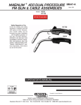
MAGNUM ® 400 DUAL PROCEDURE
GMA GUN & CABLE ASSEMBLIES
Models
IM646-A
March, 2008
K574
K1722
RETURN TO MAIN MENU
Safety Depends on You
K1722
Lincoln arc welding and cutting
equipment is designed and built
with safety in mind. However,
your overall safety can be
increased by proper installation
... and thoughtful operation on
your part. DO NOT INSTALL,
OPERATE OR REPAIR THIS
EQUIPMENT WITHOUT READING THIS MANUAL AND THE
SAFETY PRECAUTIONS CONTAINED THROUGHOUT. And,
most importantly, think before
you act and be careful.
K574
OPERATORʼS MANUAL
Copyright © Lincoln Global Inc.
• World's Leader in Welding and Cutting Products •
• Sales and Service through Subsidiaries and Distributors Worldwide •
Cleveland, Ohio 44117-1199 U.S.A. TEL: 216.481.8100 FAX: 216.486.1751 WEB SITE: www.lincolnelectric.com
i
i
SAFETY
WARNING
CALIFORNIA PROPOSITION 65 WARNINGS
Diesel engine exhaust and some of its constituents
are known to the State of California to cause cancer, birth defects, and other reproductive harm.
The Above For Diesel Engines
The engine exhaust from this product contains
chemicals known to the State of California to cause
cancer, birth defects, or other reproductive harm.
The Above For Gasoline Engines
ARC WELDING CAN BE HAZARDOUS. PROTECT YOURSELF AND OTHERS FROM POSSIBLE SERIOUS INJURY OR DEATH.
KEEP CHILDREN AWAY. PACEMAKER WEARERS SHOULD CONSULT WITH THEIR DOCTOR BEFORE OPERATING.
Read and understand the following safety highlights. For additional safety information, it is strongly recommended that you
purchase a copy of “Safety in Welding & Cutting - ANSI Standard Z49.1” from the American Welding Society, P.O. Box
351040, Miami, Florida 33135 or CSA Standard W117.2-1974. A Free copy of “Arc Welding Safety” booklet E205 is available
from the Lincoln Electric Company, 22801 St. Clair Avenue, Cleveland, Ohio 44117-1199.
BE SURE THAT ALL INSTALLATION, OPERATION, MAINTENANCE AND REPAIR PROCEDURES ARE
PERFORMED ONLY BY QUALIFIED INDIVIDUALS.
FOR ENGINE
powered equipment.
1.h. To avoid scalding, do not remove the
radiator pressure cap when the engine is
hot.
1.a. Turn the engine off before troubleshooting and maintenance
work unless the maintenance work requires it to be running.
____________________________________________________
1.b. Operate engines in open, well-ventilated
areas or vent the engine exhaust fumes
outdoors.
____________________________________________________
1.c. Do not add the fuel near an open flame
welding arc or when the engine is running.
Stop the engine and allow it to cool before
refueling to prevent spilled fuel from vaporizing on contact with hot engine parts and
igniting. Do not spill fuel when filling tank. If
fuel is spilled, wipe it up and do not start
engine until fumes have been eliminated.
____________________________________________________
1.d. Keep all equipment safety guards, covers and devices in
position and in good repair.Keep hands, hair, clothing and
tools away from V-belts, gears, fans and all other moving
parts when starting, operating or repairing equipment.
____________________________________________________
1.e. In some cases it may be necessary to remove safety
guards to perform required maintenance. Remove
guards only when necessary and replace them when the
maintenance requiring their removal is complete.
Always use the greatest care when working near moving
parts.
___________________________________________________
1.f. Do not put your hands near the engine fan.
Do not attempt to override the governor or
idler by pushing on the throttle control rods
while the engine is running.
ELECTRIC AND
MAGNETIC FIELDS
may be dangerous
2.a. Electric current flowing through any conductor causes
localized Electric and Magnetic Fields (EMF). Welding
current creates EMF fields around welding cables and
welding machines
2.b. EMF fields may interfere with some pacemakers, and
welders having a pacemaker should consult their physician
before welding.
2.c. Exposure to EMF fields in welding may have other health
effects which are now not known.
2.d. All welders should use the following procedures in order to
minimize exposure to EMF fields from the welding circuit:
2.d.1. Route the electrode and work cables together - Secure
them with tape when possible.
2.d.2. Never coil the electrode lead around your body.
2.d.3. Do not place your body between the electrode and
work cables. If the electrode cable is on your right
side, the work cable should also be on your right side.
2.d.4. Connect the work cable to the workpiece as close as
possible to the area being welded.
___________________________________________________
1.g. To prevent accidentally starting gasoline engines while
turning the engine or welding generator during maintenance
work, disconnect the spark plug wires, distributor cap or
magneto wire as appropriate.
2.d.5. Do not work next to welding power source.
Mar ʻ95
ii
ii
SAFETY
ARC RAYS can burn.
ELECTRIC SHOCK can
kill.
3.a. The electrode and work (or ground) circuits
are electrically “hot” when the welder is on.
Do not touch these “hot” parts with your bare
skin or wet clothing. Wear dry, hole-free
gloves to insulate hands.
3.b. Insulate yourself from work and ground using dry insulation.
Make certain the insulation is large enough to cover your full
area of physical contact with work and ground.
In addition to the normal safety precautions, if welding
must be performed under electrically hazardous
conditions (in damp locations or while wearing wet
clothing; on metal structures such as floors, gratings or
scaffolds; when in cramped positions such as sitting,
kneeling or lying, if there is a high risk of unavoidable or
accidental contact with the workpiece or ground) use
the following equipment:
• Semiautomatic DC Constant Voltage (Wire) Welder.
• DC Manual (Stick) Welder.
• AC Welder with Reduced Voltage Control.
3.c. In semiautomatic or automatic wire welding, the electrode,
electrode reel, welding head, nozzle or semiautomatic
welding gun are also electrically “hot”.
3.d. Always be sure the work cable makes a good electrical
connection with the metal being welded. The connection
should be as close as possible to the area being welded.
3.e. Ground the work or metal to be welded to a good electrical
(earth) ground.
3.f. Maintain the electrode holder, work clamp, welding cable and
welding machine in good, safe operating condition. Replace
damaged insulation.
3.g. Never dip the electrode in water for cooling.
3.h. Never simultaneously touch electrically “hot” parts of
electrode holders connected to two welders because voltage
between the two can be the total of the open circuit voltage
of both welders.
3.i. When working above floor level, use a safety belt to protect
yourself from a fall should you get a shock.
3.j. Also see Items 6.c. and 8.
4.a. Use a shield with the proper filter and cover
plates to protect your eyes from sparks and
the rays of the arc when welding or observing
open arc welding. Headshield and filter lens
should conform to ANSI Z87. I standards.
4.b. Use suitable clothing made from durable flame-resistant
material to protect your skin and that of your helpers from
the arc rays.
4.c. Protect other nearby personnel with suitable, non-flammable
screening and/or warn them not to watch the arc nor expose
themselves to the arc rays or to hot spatter or metal.
FUMES AND GASES
can be dangerous.
5.a. Welding may produce fumes and gases
hazardous to health. Avoid breathing these
fumes and gases. When welding, keep
your head out of the fume. Use enough
ventilation and/or exhaust at the arc to keep
fumes and gases away from the breathing zone. When
welding with electrodes which require special
ventilation such as stainless or hard facing (see
instructions on container or MSDS) or on lead or
cadmium plated steel and other metals or coatings
which produce highly toxic fumes, keep exposure as
low as possible and below Threshold Limit Values (TLV)
using local exhaust or mechanical ventilation. In
confined spaces or in some circumstances, outdoors, a
respirator may be required. Additional precautions are
also required when welding on galvanized steel.
5. b. The operation of welding fume control equipment is affected
by various factors including proper use and positioning of
the equipment, maintenance of the equipment and the specific welding procedure and application involved. Worker
exposure level should be checked upon installation and
periodically thereafter to be certain it is within applicable
OSHA PEL and ACGIH TLV limits.
5.c. Do not weld in locations near chlorinated hydrocarbon vapors
coming from degreasing, cleaning or spraying operations.
The heat and rays of the arc can react with solvent vapors to
form phosgene, a highly toxic gas, and other irritating products.
5.d. Shielding gases used for arc welding can displace air and
cause injury or death. Always use enough ventilation,
especially in confined areas, to insure breathing air is safe.
5.e. Read and understand the manufacturerʼs instructions for this
equipment and the consumables to be used, including the
material safety data sheet (MSDS) and follow your
employerʼs safety practices. MSDS forms are available from
your welding distributor or from the manufacturer.
5.f. Also see item 1.b.
AUG 06
iii
iii
SAFETY
WELDING and CUTTING
SPARKS can
cause fire or explosion.
6.a. Remove fire hazards from the welding area.
If this is not possible, cover them to prevent
the welding sparks from starting a fire.
Remember that welding sparks and hot
materials from welding can easily go through small cracks
and openings to adjacent areas. Avoid welding near
hydraulic lines. Have a fire extinguisher readily available.
6.b. Where compressed gases are to be used at the job site,
special precautions should be used to prevent hazardous
situations. Refer to “Safety in Welding and Cutting” (ANSI
Standard Z49.1) and the operating information for the
equipment being used.
6.c. When not welding, make certain no part of the electrode
circuit is touching the work or ground. Accidental contact
can cause overheating and create a fire hazard.
6.d. Do not heat, cut or weld tanks, drums or containers until the
proper steps have been taken to insure that such procedures
will not cause flammable or toxic vapors from substances
inside. They can cause an explosion even though they have
been “cleaned”. For information, purchase “Recommended
Safe Practices for the Preparation for Welding and Cutting of
Containers and Piping That Have Held Hazardous
Substances”, AWS F4.1 from the American Welding Society
(see address above).
6.e. Vent hollow castings or containers before heating, cutting or
welding. They may explode.
CYLINDER may explode
if damaged.
7.a. Use only compressed gas cylinders
containing the correct shielding gas for the
process used and properly operating
regulators designed for the gas and
pressure used. All hoses, fittings, etc. should be suitable for
the application and maintained in good condition.
7.b. Always keep cylinders in an upright position securely
chained to an undercarriage or fixed support.
7.c. Cylinders should be located:
• Away from areas where they may be struck or subjected to
physical damage.
• A safe distance from arc welding or cutting operations and
any other source of heat, sparks, or flame.
7.d. Never allow the electrode, electrode holder or any other
electrically “hot” parts to touch a cylinder.
7.e. Keep your head and face away from the cylinder valve outlet
when opening the cylinder valve.
7.f. Valve protection caps should always be in place and hand
tight except when the cylinder is in use or connected for
use.
7.g. Read and follow the instructions on compressed gas
cylinders, associated equipment, and CGA publication P-l,
“Precautions for Safe Handling of Compressed Gases in
Cylinders,” available from the Compressed Gas Association
1235 Jefferson Davis Highway, Arlington, VA 22202.
6.f. Sparks and spatter are thrown from the welding arc. Wear oil
free protective garments such as leather gloves, heavy shirt,
cuffless trousers, high shoes and a cap over your hair. Wear
ear plugs when welding out of position or in confined places.
Always wear safety glasses with side shields when in a
welding area.
6.g. Connect the work cable to the work as close to the welding
area as practical. Work cables connected to the building
framework or other locations away from the welding area
increase the possibility of the welding current passing
through lifting chains, crane cables or other alternate circuits. This can create fire hazards or overheat lifting chains
or cables until they fail.
6.h. Also see item 1.c.
6.I. Read and follow NFPA 51B “ Standard for Fire Prevention
During Welding, Cutting and Other Hot Work”, available
from NFPA, 1 Batterymarch Park,PO box 9101, Quincy, Ma
022690-9101.
6.j. Do not use a welding power source for pipe thawing.
FOR ELECTRICALLY
powered equipment.
8.a. Turn off input power using the disconnect
switch at the fuse box before working on
the equipment.
8.b. Install equipment in accordance with the U.S. National
Electrical Code, all local codes and the manufacturerʼs
recommendations.
8.c. Ground the equipment in accordance with the U.S. National
Electrical Code and the manufacturerʼs recommendations.
Jan, 07
iv
iv
SAFETY
PRÉCAUTIONS DE SÛRETÉ
Pour votre propre protection lire et observer toutes les instructions
et les précautions de sûreté specifiques qui parraissent dans ce
manuel aussi bien que les précautions de sûreté générales suivantes:
Sûreté Pour Soudage A LʼArc
1. Protegez-vous contre la secousse électrique:
a. Les circuits à lʼélectrode et à la piéce sont sous tension
quand la machine à souder est en marche. Eviter toujours
tout contact entre les parties sous tension et la peau nue
ou les vétements mouillés. Porter des gants secs et sans
trous pour isoler les mains.
b. Faire trés attention de bien sʼisoler de la masse quand on
soude dans des endroits humides, ou sur un plancher
metallique ou des grilles metalliques, principalement dans
les positions assis ou couché pour lesquelles une grande
partie du corps peut être en contact avec la masse.
c. Maintenir le porte-électrode, la pince de masse, le câble
de soudage et la machine à souder en bon et sûr état
defonctionnement.
d.Ne jamais plonger le porte-électrode dans lʼeau pour le
refroidir.
e. Ne jamais toucher simultanément les parties sous tension
des porte-électrodes connectés à deux machines à souder
parce que la tension entre les deux pinces peut être le
total de la tension à vide des deux machines.
f. Si on utilise la machine à souder comme une source de
courant pour soudage semi-automatique, ces precautions
pour le porte-électrode sʼapplicuent aussi au pistolet de
soudage.
2. Dans le cas de travail au dessus du niveau du sol, se protéger
contre les chutes dans le cas ou on recoit un choc. Ne jamais
enrouler le câble-électrode autour de nʼimporte quelle partie
du corps.
3. Un coup dʼarc peut être plus sévère quʼun coup de soliel,
donc:
a. Utiliser un bon masque avec un verre filtrant approprié
ainsi quʼun verre blanc afin de se protéger les yeux du rayonnement de lʼarc et des projections quand on soude ou
quand on regarde lʼarc.
b. Porter des vêtements convenables afin de protéger la
peau de soudeur et des aides contre le rayonnement de
lʻarc.
c. Protéger lʼautre personnel travaillant à proximité au
soudage à lʼaide dʼécrans appropriés et non-inflammables.
4. Des gouttes de laitier en fusion sont émises de lʼarc de
soudage. Se protéger avec des vêtements de protection libres
de lʼhuile, tels que les gants en cuir, chemise épaisse, pantalons sans revers, et chaussures montantes.
5. Toujours porter des lunettes de sécurité dans la zone de
soudage. Utiliser des lunettes avec écrans lateraux dans les
zones où lʼon pique le laitier.
6. Eloigner les matériaux inflammables ou les recouvrir afin de
prévenir tout risque dʼincendie dû aux étincelles.
7. Quand on ne soude pas, poser la pince à une endroit isolé de
la masse. Un court-circuit accidental peut provoquer un
échauffement et un risque dʼincendie.
8. Sʼassurer que la masse est connectée le plus prés possible
de la zone de travail quʼil est pratique de le faire. Si on place
la masse sur la charpente de la construction ou dʼautres
endroits éloignés de la zone de travail, on augmente le risque
de voir passer le courant de soudage par les chaines de levage, câbles de grue, ou autres circuits. Cela peut provoquer
des risques dʼincendie ou dʼechauffement des chaines et des
câbles jusquʼà ce quʼils se rompent.
9. Assurer une ventilation suffisante dans la zone de soudage.
Ceci est particuliérement important pour le soudage de tôles
galvanisées plombées, ou cadmiées ou tout autre métal qui
produit des fumeés toxiques.
10. Ne pas souder en présence de vapeurs de chlore provenant
dʼopérations de dégraissage, nettoyage ou pistolage. La
chaleur ou les rayons de lʼarc peuvent réagir avec les vapeurs
du solvant pour produire du phosgéne (gas fortement toxique)
ou autres produits irritants.
11. Pour obtenir de plus amples renseignements sur la sûreté,
voir le code “Code for safety in welding and cutting” CSA
Standard W 117.2-1974.
PRÉCAUTIONS DE SÛRETÉ POUR
LES MACHINES À SOUDER À
TRANSFORMATEUR ET À
REDRESSEUR
1. Relier à la terre le chassis du poste conformement au code de
lʼélectricité et aux recommendations du fabricant. Le dispositif
de montage ou la piece à souder doit être branché à une
bonne mise à la terre.
2. Autant que possible, Iʼinstallation et lʼentretien du poste seront
effectués par un électricien qualifié.
3. Avant de faires des travaux à lʼinterieur de poste, la debrancher à lʼinterrupteur à la boite de fusibles.
4. Garder tous les couvercles et dispositifs de sûreté à leur
place.
Mar. ʻ93
v
v
Thank You
for selecting a QUALITY product by Lincoln Electric. We want you
to take pride in operating this Lincoln Electric Company product
••• as much pride as we have in bringing this product to you!
CUSTOMER ASSISTANCE POLICY
The business of The Lincoln Electric Company is manufacturing and selling high quality welding equipment, consumables, and cutting equipment. Our challenge is to meet the needs of our customers and to exceed their expectations. On occasion, purchasers may ask Lincoln
Electric for advice or information about their use of our products. We respond to our customers based on the best information in our possession at that time. Lincoln Electric is not in a position to warrant or guarantee such advice, and assumes no liability, with respect to such information or advice. We expressly disclaim any warranty of any kind, including any warranty of fitness for any customerʼs particular purpose,
with respect to such information or advice. As a matter of practical consideration, we also cannot assume any responsibility for updating or
correcting any such information or advice once it has been given, nor does the provision of information or advice create, expand or alter any
warranty with respect to the sale of our products.
Lincoln Electric is a responsive manufacturer, but the selection and use of specific products sold by Lincoln Electric is solely within the control
of, and remains the sole responsibility of the customer. Many variables beyond the control of Lincoln Electric affect the results obtained in
applying these types of fabrication methods and service requirements.
Subject to Change – This information is accurate to the best of our knowledge at the time of printing. Please refer to www.lincolnelectric.com
for any updated information.
Please Examine Carton and Equipment For Damage Immediately
When this equipment is shipped, title passes to the purchaser upon receipt by the carrier. Consequently, Claims
for material damaged in shipment must be made by the purchaser against the transportation company at the
time the shipment is received.
Please record your equipment identification information below for future reference. This information can be
found on your machine nameplate.
Product _________________________________________________________________________________
Model Number ___________________________________________________________________________
Code Number or Date Code_________________________________________________________________
Serial Number____________________________________________________________________________
Date Purchased___________________________________________________________________________
Where Purchased_________________________________________________________________________
Whenever you request replacement parts or information on this equipment, always supply the information you
have recorded above. The code number is especially important when identifying the correct replacement parts.
On-Line Product Registration
- Register your machine with Lincoln Electric either via fax or over the Internet.
• For faxing: Complete the form on the back of the warranty statement included in the literature packet
accompanying this machine and fax the form per the instructions printed on it.
• For On-Line Registration: Go to our WEB SITE at www.lincolnelectric.com. Choose “Quick Links” and then
“Product Registration”. Please complete the form and submit your registration.
Read this Operators Manual completely before attempting to use this equipment. Save this manual and keep it
handy for quick reference. Pay particular attention to the safety instructions we have provided for your protection.
The level of seriousness to be applied to each is explained below:
WARNING
This statement appears where the information must be followed exactly to avoid serious personal injury or loss of life.
CAUTION
This statement appears where the information must be followed to avoid minor personal injury or damage to this equipment.
vi
vi
TABLE OF CONTENTS
Page
Installation ..................................................................................................................... Section A
General Description ......................................................................................................A-1, A-2
Connector Kit Installation to Gun Cable ............................................................................. A-3
K466-1 &-8 Installation ................................................................................................ A-3
K466-2 Installation ...................................................................................................... A-3
K466-3 Installation ...................................................................................................... A-3
K466-5 Installation ...................................................................................................... A-4
K466-7, & -10 Installation ............................................................................................ A-4
Liner Installation & Trimming Instructions ........................................................................... A-5
Installation of M18732 Series Liners for Feeding Aluminum Electrode ................................A-5
Contact Tip and Gas Nozzle Installation ............................................................................ A-6
Connection to Feeder ......................................................................................................... A-6
Connection to Lincoln Feeders ................................................................................... A-6
Connection to Adapted Feeders ................................................................................. A-7
Connection to Miller Feeders ...................................................................................... A-7
Connection to Hobart 2000 Feeders ........................................................................... A-7
Connection to -10 Series Feeders .............................................................................. A-7
_______________________________________________________________________________________
Operation ....................................................................................................................... Section B
Electrodes and Equipment ................................................................................................. B-1
Making a Weld .................................................................................................................... B-1
Avoiding Wire Feeding Problems ....................................................................................... B-1
_______________________________________________________________________________________
Maintenance .................................................................................................................. Section D
Removal, Installation and Trimming Instructions for Magnum® Liners .............................. D-1
Gun Tubes and Nozzles ..................................................................................................... D-1
Gun Cables ........................................................................................................................ D-1
Cable Cleaning ........................................................................................................... D-1
Cable Repair (K574 & K1722 Models) ................................................................................ D-1
Gun Tube End Repair .................................................................................................. D-1
Wire Feeder End Repair .............................................................................................. D-4
Thread Sizes for 400 Amp Consumables .....................................................................D-7
_______________________________________________________________________________________
Troubleshooting ........................................................................................................... Section E
_______________________________________________________________________________________
Parts Lists ...................................................................................................... P202-L and P202-X
_______________________________________________________________________________________
MAGNUM® 400 DUAL PROCEDURE GUNS
A-1
A-1
INSTALLATION
GENERAL DESCRIPTION
The Magnum®™ 400 DP Dual Procedure GMA gun
and cable assemblies have been designed to meet
NEMA specification EW3 for welding with steel electrode using the GMAW (gas metal arc welding) and
gas-shielded FCAW (flux-cored arc welding) processes. Magnum® 400 DP guns and cables are specifically designed for use with wire feeders with dual procedure capabilities. The K574 gun is equipped with a
two position trigger. Pulling the trigger in part of the
way will engage the first procedure set at the feeder.
Pulling the trigger the rest of the way will engage the
second procedure. An interlocking trigger is available
as a parts order. The K1722 Magnum® 400 DP Dual
Proecdure gun and cables are also designed for use
with wire feeders with dual procedure capabilities. The
guns are equipped with a rocker switch that is used to
select one of two welding procedures.
The K574 and K1722 are designed for use with K466
connector kits. The proper connector can be installed
the same as with any Magnum® Gun. The gun control cable connections however must be tailored to
each specific machine. The K574 comes with control
wires but no specific connectors are provided. The
K1722 has a connector that will mate with any Lincoln
-10 series wire feeder.
The Magnum® 400 DP guns are not factory equipped
with a feeder end connector. With the K466-1
Magnum® Connector Kit, they can be used with any
Lincoln LN-7 or LN-25 semiautomatic wire feeder. The
K466-1 should also be used with the LN-8 or LN-9
when feeding .052 and smaller electrodes. An optional
K481 Magnum® Fast-Connect Gas Tube Kit is available to provide tool-less gas tube connection to
Lincoln wire feeders. Non-GMA model wire feeders
require an optional gas solenoid valve.
The K466-6 connector kit allows connection of
Magnum® 400 DP guns to a Lincoln Wirematic.
The K466-7 connector kit allows connection of
Magnum® 400 DP guns to Hobart Series 2000 Wire
Feeders.
The K466-8 connector kit allows connection of
Magnum® 400 DP guns to an LN8 or LN9 when 1/16
and larger electrode is used.
The K466-9 connector kit allows connection of K497
to SP100T and related wire feeders.
The K466-10 connector kit allows connection of
Magnum® 400 DP guns to a 10 Series wire feeder.
The Magnum® 400 DP gun and cable assemblies are
fully compatible for use with comparable Tweco gun
size tips, diffusers, gas nozzles, and cable liners. The
Magnum® GMA gun family offers an expanding line of
quality, long life, expendable replacement parts and
accessories.
For best results when welding mild and alloy steels, it
is recommended that L-50 or L-56 Lincoln solid wire
electrodes be used for the GMAW process and
Lincoln Outershield cored electrodes for the gasshielded FCAW process.
WARNING
• Do not touch electrically live parts
such as output terminals or internal
wiring
------------------------------------------------------------------------
The 400 DP guns can also be used with any wire
feeder equipped with a Tweco® #1, 2, 3, 350 or 4 wire
feed adapter kit by using the K466-2 Magnum®
Connector Kit.
With the K466-3 or K466-4 Magnum® connector kits,
it is possible to connect Magnum® 400 guns directly
to a variety of Miller and Hobart wire feeders, respectively.
The K466-5 connector kit allows connection of
Magnum® 400 DP guns to an L Tec feeder connector
assembly. L-Tec feeders require a feeder connector
assembly (similar to a Tweco® adapter) in order to
connect to a gun and cable. The K466-5 contains a
brass connector to permit Magnum® guns to be connected to this feeder connector assembly.
MAGNUM® 400 DUAL PROCEDURE GUNS
A-2
A-2
INSTALLATION
MAGNUM® 400 Dual Procedure
400 AMPS at 60% DUTY CYCLE WITH CO2 GAS
400 AMPS at 50% DUTY CYCLE WITH MIXED GAS
Description
Product
Number
Gun
Cable
Length (m)
Wire Size
in. (mm)
K574-1
15 ft
(4.5)
.035 (0.9)
.045 (1.2)
K574-2
15 ft
(4.5)
K574-3
Contact Tips
Standard
Duty
Gas
Diffuser
Assembly
Gas
Nozzle
Insulator
Cable
Liner
Gun Tube
60°
KP14-35
-45
KP54A
KP24A-62
KP34A
KP44-3545-15
KP1928-1
.052 (1.3)
1/16 (1.6)
KP14-52
-116
KP54A
KP24A-62
KP34A
KP44-116-15
KP1928-1
15 ft
(4.5)
1/16 (1.6)
5/64 (2.0)
KP14-116
-564
KP54A
KP24A-62
KP34A
KP44-564-15
KP1928-1
K574-4
25 ft
(7.6)
.035 (0.9)
.045 (1.2)
KP14-35
-45
KP54A
KP24A-62
KP34A
KP44-3545-25
KP1928-1
K574-5
25 ft
(7.6)
.052 (1.3)
1/16 (1.6)
KP14-52
-116
KP54A
KP24A-62
KP34A
KP44-116-25
KP1928-1
K574-6
25 ft
(7.6)
1/16 (1.6)
5/64 (2.0)
KP14-116
-564
KP54A
KP24A-62
KP34A
KP44-564-25
KP1928-1
K1722-1
10 ft.
(3.0)
.035 (0.9)
.045 (1.2)
KP14-35
-45
KP54A
KP24A-62
KP34A
KP44-3545-15
KP1928-1
K1722-2
15 ft.
(4.5)
.035 (0.9)
.045 (1.2)
KP14-35
-45
KP54A
KP24A-62
KP34A
KP44-3545-15
KP1928-1
K1722-3
25 ft.
(7.6)
.035 (0.9)
.045 (1.2)
KP14-35
-45
KP54A
KP24A-62
KP34A
KP44-3545-25
KP1928-1
MAGNUM® 400 DUAL PROCEDURE GUNS
A-3
INSTALLATION
Read this entire installation section before you
start installation.
SAFETY PRECAUTIONS
WARNING
ELECTRIC SHOCK can kill.
• Do not touch electrically live parts
such as output terminals or internal wiring.
• Insulate yourself from the work and
ground.
• Always wear dry insulating gloves.
-----------------------------------------------------------------------Only qualified personnel should install, use or
service this equipment.
CONNECTOR KIT INSTALLATION TO GUN
CABLE
The K574 and K1722 Magnum® 400 dual procedure
cables are shipped as generic assemblies and must
be assembled with a connector kit.
NOTE: The K574 Magnum® 400 DP gun and cable is
not only shipped with a generic wire feeder end, it
is also shipped with generic gun control assemblies. The brass connector can be installed per
K466 instructions, but the gun control cable must
be tailored, by the user, to the specific machine.
To install on an LN-9 Lincoln wire feeder equipped
with a dual procedure kit, connect the cable marked
"1" to pin receptacles "A" and "C" of a S12020-6
five pin Amphenol plug (optional). (S12024-1 cable
clamp is required to secure the Amphenol plug to
the cable.) Connect the cable marked "2" to pin
receptacles "A" and "C" of a S12020-16 three pin
Amphenol plug (optional). (S12024-4 cable clamp
is required to secure Amphenol plug to the cable.)
To install on a DH-10 Lincoln wire feeder, a
S12024-12 cable clamp and a S12020-6 five pin
Amphenol plug are required. Slip the two control
cables through the cable clamp and connect the
two control cables to the Amphenol plug. Connect
the two leads of cable marked “1" to pins A & C and
connect the two leads of cable marked “2" to pins D
& E. Connect the cable clamp to the plug and
secure the leads.
The K1722 Magnum® 400DP gun and cable is
equipped with a control cable that attaches to a
Lincoln -10 series wire feeder. For other wire feeders the control cable has to be rewired with the
appropriate connectors to fit the wire feeder.
A-3
K466-1& -8 INSTALLATION (For Lincoln Feeders)
a. Remove brass cable connector and insulation tube
(see Figure B.1) from the kit. Slide the insulation
tube onto the connector from the threaded end and
screw it onto the feeder end of the gun cable.
Tighten the connection with the wrench provided.
b. Remove the molded gas plug fitting on the side of
the feeder end handle and replace it with the
barbed brass fitting provided in the kit. The included wrench will fit both the gas plug and barbed fitting.
c. The gun control cable provided is not used.
d. Place one tubing clamp onto each end of the flexible tubing provided, approximately 2” (51 mm) in
from each end. Slide one end of the tubing onto the
barbed connector on the feeder end cable handle
(step b) and move the clamp down near the end of
the tube to ensure a good gas seal.
NOTE: An optional K481 Magnum® Fast-Connect
Gas Tube Kit is available to provide tool-less gas
tube connection to Lincoln wire feeders. Install per
the instructions included with the kit.
K466-2 INSTALLATION (For Adapted Feeders and
-10 Series Lincoln Feeders)
a. Remove brass cable connector (see Figure B.1)
from the kit and screw it onto the feeder end of the
gun cable. Tighten the connection with the wrench
provided.
b. Check that the molded gas plug fitting is sealing
the gas fitting hole in the side of the feeder end
handle.
K466-3 INSTALLATION (For Miller Feeders; i.e.
Millermatic 200, Cricket, S-32P, 54D...)
a. Remove brass cable connector (see Figure B.1)
from the kit and screw it onto the feeder end of the
gun cable. Tighten the connection with the wrench
provided.
b. Check that the molded gas plug fitting is sealing
the gas fitting hole in the side of the feeder end
handle.
c. The gun control cable provided is not used.
MAGNUM® 400 DUAL PROCEDURE GUNS
A-4
INSTALLATION
K466-5 INSTALLATION (For L-Tec Feeders
equipped with an L-Tec feeder connector assembly,
MIG 35, MIG 31A, 225...)
a. Remove brass cable connector (see Figure B.1)
from the kit and screw it onto the feeder end of the
gun cable. Tighten the connection with the wrench
provided.
b. Check that the molded gas plug fitting is sealing
the gas fitting hole in the side of the feeder end
handle.
c. The gun control cable provided is not used.
K466-7, and K466-10 Installation (Hobart Series
2000 Feeders, and Lincoln -10 Series Feeders)
a. Remove brass cable connector (see Figure B.1)
from the connector kit and screw it onto the feeder
end of the gun cable. Tighten the connection with
the wrench provided.
b. Check that the molded gas plug fitting is sealing
the gas fitting hole in the side of the feeder end
handle.
c. The gun control cable provided is not used.
Figure B.1
MAGNUM® 400 DUAL PROCEDURE GUNS
A-4
A-5
A-5
INSTALLATION
LINER INSTALLATION AND TRIMMING INSTRUCTIONS
Installation of (KP44 and KP44N liner series)
a. Lay the gun and cable straight on a flat surface.
b. Make sure that the set screw in the connector end
is backed out so as not to damage liner or liner
bushing. Remove and save the gas nozzle, nozzle
insulator, and gas diffuser from the end of the gun
tube assembly.
c. Insert a new untrimmed liner into the connector
end of the cable. Be sure the liner bushing is stenciled appropriately for the wire size being used.
NOTE: For KP44N and KP45N liner series.
Before fully seating the liner bushing, it will be necessary to trim the linerʼs inner tube flush with the
liner bushing using a sharp blade. After trimming,
remove any burrs from inner tube and insure that
the opening is fully open.
d. Before installing the gas diffuser, fully seat the liner
bushing in the connector and:
For all K466 connector kits except K466-3 and
K466-4, tighten the set screw in the cable connector.
or
For K466-3 and K466-4, screw in the connector
cap provided in the kit until it seats on the face of
the bushing. Then insert the appropriate piece of
liner material into the connector cap and tighten the
set screw. Three pieces of liner material are included in these connector kits to help guide the electrode through the connector cap. The piece with
the smallest inner diameter is designed for .045”
(1.2 mm) maximum diameter electrode. The next
largest diameter is for 1/16” (1.6 mm) maximum
diameter electrode. The largest diameter piece of
liner material is for 5/64” (2.0 mm) maximum diameter electrode.
e. Be sure the cable is straight and then trim the liner
to the length shown in Figure B.1 (a gauge is
included on the wrench provided with the connection kit for gauging the cut-off length on 300 and
400 amp gun tubes). Remove any burrs from the
end of the liner.
f. Screw the gas diffuser onto the end of the gun tube
and tighten with the wrench provided.
g. Tighten the set screw in the side of the gas diffuser
against the cable liner using the Allen wrench provided.
CAUTION
This screw should only be gently tightened.
Overtightening will split or collapse the liner and
cause poor wire feeding.
-----------------------------------------------------------------------h. Replace the nozzle insulator and gas nozzle.
INSTALLATION OF KP1958 SERIES LINERS FOR
FEEDING ALUMINUM ELECTRODE
1. Lay the gun out straight on a flat surface and
remove the gas nozzle.
A. For all K466 except K466-3 and K466-4 connections, back out the set screw in the connector
end with a 5/64 (2.0 mm) Allen wrench.
B. For all K466-3 and K466-4 connections: Remove
the connector cap.
C. Back out the set screw in the diffuser for guns
that have a set screw in the diffuser.
2. Remove the liner and insert a new untrimmed liner
into the connector end of the cable. Check that the
coils of the spring liner can be seen through the
holes in the gas diffuser.
A. For all K466-3 and K466-4 connections: If the
liner is going to be replaced with a different size
liner, loosen the set screw on the connector cap
and replace the liner material with the correct
size.
3. Mark the liner 3/16" (5 mm) from the end of the
liner guide or connector. Pull the liner partially out
and cut off the liner at the mark using a sharp
knife.
4. Screw the brass liner nipple onto the liner and fully
seat the liner busing into the liner guide or the connector.
A. For connector kits, except K466-3 and K466-4,
tighten the set screw in the cable connector.
B. For K466-3 and K466-4, screw in the connector
cap.
5. For guns with a diffuser set screw, tighten the set
screw in the side of the gas diffuser against the
cable liner using the Allen wrench provided.
CAUTION
This screw should only be gently tightened.
Overtightening will split or collapse the liner and
cause poor wire feeding.
-----------------------------------------------------------------------6. Replace the nozzle insulator and gas nozzle.
MAGNUM® 400 DUAL PROCEDURE GUNS
A-6
INSTALLATION
A-6
CONTACT TIP AND GAS NOZZLE INSTALLATION
CONNECTION TO LINCOLN FEEDERS
a. Choose the correct size contact tip for the electrode being used (wire size is stenciled on the side
of the contact tip) and screw it snugly into the gas
diffuser.
Gun cable assemblies which were assembled with a
K466-1 or -8 Connection Kit will connect easily to any
Lincoln LN-9 with a dual procedure kit.
b. Be sure the nozzle insulator is fully screwed onto
the gun tube and does not block the gas holes in
the diffuser. (NOTE: Insulator is not required when
using the optional fixed gas nozzles.)
c. Slip the appropriate gas nozzle onto the nozzle
insulator. Adjustable gas nozzles are available with
a .62” (15.9 mm) or .50” (12.7 mm) I.D., and in both
standard (flush) and recessed design. The proper
nozzle should be selected based on the welding
application. Different length fixed nozzles are also
available to fit 400 amp gun tubes to allow either
spray or short-circuiting transfer welding.
Choose the gas nozzle as appropriate for the
GMAW process to be used. Typically, the contact
tip end should be flush to .12” (3 mm) extended for
the short-circuiting transfer process and .12” (3
mm) recessed for spray transfer and for the
Outershield7 (FCAW) process.
a. Check that the drive roll(s) and feeder guide tubes
are appropriate for the electrode size being used.
b. Fully push the brass connector end of the gun
cable into the conductor block on the outgoing side
of the feeder wire drive. Secure the cable using the
hand screw or set screw in the conductor block.
c. Insert the control cable plug from the gun into the
mating sockets on the wire feeder.
d. Slide the free end of the flexible hose onto the
barbed gas fitting on the front of the Lincoln feeder.
Move the corresponding tubing clamp down near
the end of the tube to assure a good gas seal.
CONNECTION TO ADAPTED FEEDERS
Gun cable assemblies which were assembled with a
K466-2 Connection Kit will connect easily to any properly adapted feeder.
CONNECTION TO FEEDER
NOTE: The K574 Magnum® 400 DS is shipped with
generic gun control cables, therefore Section (c) will
not apply. The gun control cables must be tailored, by
the user, to each specific wire feeder. The cables are
identified as procedure 1 and 2.
To install on Lincoln wirefeeders equipped with a dual
procedure kit, connect the cable marked "1" to the 5
pin amphenol located on the feeder case front. The
cable marked "2" should be connected to the 3 pin
amphenol located on the dual procedure box.
a. Check that the adapter and feeder outgoing guide,
as well as the drive roll, are appropriate for the
electrode size being used.
b. Fully push the brass connector end of the gun
cable into the brass adapter on the outgoing side of
the feeder wire drive. Secure the cable using the
hand screw or set screw in the adapter.
c. Insert the control cable plug into the mating socket
on the wire feeder.
MAGNUM® 400 DUAL PROCEDURE GUNS
A-7
INSTALLATION
A-7
CONNECTION TO MILLER FEEDERS
CONNECTION TO LINCOLN -10 SERIES FEEDERS
Gun and cable assemblies which were assembled
with a K466-3 Connector Kit will connect easily to a
variety of popular Miller wire feeders.
Gun cable assemblies which were assembled with a
K466-10 Connection Kit or K471-21 thru -23 gun and
cable assemblies will connect easily to a -10 Series
feeder.
a. Check that the gun liner, connector cap liner, drive
rolls and guide tubes are appropriate for the electrode size being used.
b. Fully push the brass connector end of the gun and
cable into the connector receptacle on the outgoing
side of the feeder wire drive. Tighten the hand
screw to clamp down on the connector.
c. Insert the control cable plug into the mating socket
on the wire feeder.
a. Check that the K1500-2 gun adapter is in place on
the wire feeder. Check that the feeder guide tubes,
as well as the drive roll(s), are appropriate for the
electrode size being used.
b. Fully push the brass connector end of the gun
cable into the gun adapter on the outgoing side of
the feeder wire drive and secure the cable using
the hand screw.
c. Insert the control cable plug into the mating socket
on the wire feeder.
CONNECTION TO HOBART 2000 FEEDERS
Gun and cable assemblies which were assembled
with a K466-7 Connector Kit will connect easily to a
variety of Hobart wire feeders.
a. Check that the adapter and feeder outgoing guide,
as well as the drive roll, are appropriate for the
electrode size being used.
b. Fully push the brass connector end of the gun
cable into the outgoing side of the feeder wire
drive. Secure the cable using the hand screw on
the wire feeder.
c. Connect the control cable plug into the mating
socket on the wire feeder.
MAGNUM® 400 DUAL PROCEDURE GUNS
B-1
OPERATION
B-1
ELECTRODES AND EQUIPMENT
a. Check that the welding power source is on and that
the shielding gas supply is set for the proper flow rate.
The Magnum® 400 Dual Procedure guns and cables
have been designed for use with Lincoln L-50 and
Super Arc L-56, solid steel wire electrodes for the
GMAW process and Lincoln Outershield7 cored electrodes for the gas-shielded FCAW process. Refer to
the appropriate Lincoln Process and Procedure
Guidelines for the electrode used for information on
recommended electrical and visible stickouts.
b. For the Magnum® 400 with dual procedure switch set
the rocker switch to the desired procedure.
MAKING A WELD
WARNING
Do not attempt to use this equipment until you
have thoroughly read all operating and maintenance manuals supplied with your machine. They
include important safety precautions, detailed
engine starting, operating and maintenance
instructions and parts lists.
ELECTRIC SHOCK can kill.
c. Position electrode over joint. End of the electrode
should be slightly off the work.
d. Lower welding helmet. close gun trigger and begin
welding. Hold the gun so the contact tip to work distance gives the correct electrical stickout as required
for the procedure being used.
e. To stop welding, release the gun trigger and then pull
the gun away from the work after the arc goes out.
Follow wire feeder instruction manual if using a trigger
interlock circuit.
f. When using a K574 Magnum® 400 Dual Procedure
gun and cable, the trigger operates as follows:
-Pulling the trigger in part of the way will engage the
first procedure set at the feeder.
-Pulling the trigger the rest of the way will engage the
second procedure.
If the optional interlocking trigger is installed,
• Do not touch electrically live parts
such as output terminals or internal wiring.
• Insulate yourself from the work and
ground.
• Always wear dry insulating gloves.
-----------------------------------------------------------------------FUMES AND GASES can be dangerous.
• Keep your head out of fumes.
-With the trigger pulled in all the way, the trigger can
be slid forward into the interlock position.
-To release interlock, squeeze trigger and pull back.
g. When using the K1722 Magnum® 400 with dual procedure switch, the trigger only starts and stops the
welding. The procedure is changed by actuating the
rocker switch that is built into the top of the gun.
AVOIDING WIRE FEEDING PROBLEMS
Wire feeding problems can be avoided by observing the
following gun handling procedures:
a. Do not kink or pull cable around sharp corners.
• Use ventilation or exhaust to
remove fumes from breathing zone.
-----------------------------------------------------------------------WELDING SPARKS can cause fire or
explosion.
• Keep flammable material away.
-----------------------------------------------------------------------ARC RAYS can burn.
• Wear eye, ear and body protection.
-----------------------------------------------------------------------Only qualified personnel should operate this
equipment.
b. Keep the electrode cable as straight as possible when
welding or loading electrode through cable.
c. Avoid wrapping excess cable around handle or front
of wire feeder especially on longer 20 and 25 ft (6.1
and 7.6 m) length guns.
d. Do not allow dolly wheels or trucks to run over cables.
e. Keep cable clean by following maintenance instructions.
f. Use only clean, rust-free electrode. The Lincoln electrodes have proper surface lubrication.
g. Replace contact tip when the arc starts to become
unstable or the contact tip end is fused or deformed.
MAGNUM® 400 DUAL PROCEDURE GUNS
D-1
D-1
MAINTENANCE
REMOVAL,
INSTALLATION
TRIMMING
INSTRUCTIONS
MAGNUM® LINERS
AND
FOR
NOTE: The variation in cable lengths prevents the
interchangeability of liners. Once a liner has been cut
for a particular gun, it should not be installed in another gun, unless it can meet the liner cut off length
requirement. Liners used to feed steel wire are
shipped with the jacket of the liner extended the proper amount.
a. Remove the gas nozzle and nozzle insulator.
Loosen the set screw located in the side of the diffuser with 5/64 (2.0 mm) Allen wrench (provided
with the gun or connector kit).
b. Remove the gas diffuser from gun.
NOTE: Small set screw in the diffuser must be
loosened, otherwise liner could be damaged when
attempting to remove gun tube.
Pull gun tube out from gun handle. To reinstall,
insert the gun tube, push in as far as possible and
retighten screws.
GUN CABLES
CABLE CLEANING
Clean cable liner after using approximately 300
pounds (136 kg) of electrode. Remove the cable from
the wire feeder and lay it out straight on the floor.
Remove the contact tip from the gun. Using an air
hose and only partial pressure, gently blow out the
cable liner from the gas diffuser end.
c. Lay gun and cable out straight on a flat surface.
For all K466 except K466-3 and K466-4
Connections:
Loosen set screw located in the brass cable connector at the wire feeder end of the cable using the
same 5/64 (2.0 mm) Allen wrench. Pull liner out of
cable. (REFER TO Figure B.1 IN INSTALLATION
FOR EACH)
<OR>
For K466-3 and K466-4 CONNECTIONS:
Remove the connector cap with the wrench provided. Pull liner out of cable. If the liner is going to be
replaced with a different size liner, loosen set
screw on the connector cap and remove piece of
liner material.
d. For installation and trimming instructions for
Magnum® liners see “LINER INSTALLATION” in
the INSTALLATION section.
GUN TUBES AND NOZZLES
a. Replace worn contact tips as required.
b. Remove spatter from inside of gas nozzle and from
tip after each 10 minutes of arc time or as required.
c. To remove gun tube from gun, loosen socket-head
clamping screw in handle with 3/16” (4.8 mm) Allen
wrench. Remove gas nozzle and nozzle insulator
and also loosen small set screw in the diffuser
using 5/64” (2.0 mm) Allen wrench.
CAUTION
Excessive pressure at the start may cause the dirt
to form a plug.
-----------------------------------------------------------------------Flex the cable over its entire length and again blow
out the cable. Repeat this procedure until no further
dirt comes out.
CABLE REPAIR
CABLE REPAIR FOR K574 & K1722
MODELS
Magnum® 400 Dual Procedure guns and cables feature the use of repairable cable connectors. If the
cable ever gets severely damaged, it may be cut
shorter and repaired by the user.
GUN TUBE END CABLE REPAIR FOR
K574 AND K1722 (Requires 4 #S8053-169
Terminals for K574 or 2 #S19492-2 terminals for K1722)
a) Remove the cable liner per previous instructions.
b) Remove the gun tube per previous instructions.
c) Remove the #6 screws from the gun handle, separate the two halves, and remove the cable from the
handle along with the trigger assembly for the
K574 guns. Before removing the trigger assembly,
carefully note trigger lead wiring as it will be important to reconnect these properly. For the K1722
also remove the rocker switch.
MAGNUM® 400 DUAL PROCEDURE GUNS
D-2
D-2
MAINTENANCE
(4 CONTROL LEADS)
CABLE
CONTROL LEAD
Figure E.1
d) Remove gun tube connector from cable by
unscrewing connector nut from gun tube connector. If the cable inner tube is difficult to remove
from the connector assembly, carefully slit it lengthwise with a knife up to the brass connector.
e) Uncouple the strain relief by pushing its outer
housing toward the middle of the cable. Move the
strain relief and the cable boot toward the middle of
the cable, past the damaged section.
f) For K574 models
Cut off damaged section of cable and strip off the
outer jacket 2.15 inches back. Be careful not to cut
the insulation on the control wires while stripping
jacket. Pull control leads back and trim the
exposed copper and inner tube back .50 inch.
Strip all four control leads .125 inch back and crimp
a new S8053-169 terminal to each lead. Apply
heat shrink tubing or electrical tape to terminals to
prevent electrical contact with other terminals. (See
Figure E.1).
For K1722 models:
Cut off damaged section of cable and strip off the
outer jacket 1.65 inches back. Be careful not to cut
the insulation on the control wires while stripping jacket. Strip all four control leads .25 inch back and crimp
a new S19492-2 terminal to both the black lead and
the white lead. Remove the leads connected to the
red and blue control leads from the cutoff cable and
solder these leads to the blue and red leads of the
newly trimmed cable. Insulate connections with heat
shrink tubing or tape. (See Figure E.2).
1/4" (6.4mm) SKIN
(4 CONTROL LEADS)
CABLE
CONTROL LEADS
(41.9mm SKIN)
Figure E.2
MAGNUM® 400 DUAL PROCEDURE GUNS
D-3
D-3
MAINTENANCE
g) Check that the cable boot and both halves of the
strain relief are on the cable. Slip the connector
nut over the copper strands with the thread end
out. Orient gun tube connector so machined flat is
on the same side of the cable as the red and white
control leads. Assemble gun tube connector to
cable by forcing the steel tube of the connector into
the inside diameter of the cable inner tube until the
copper strands are butted against the gun tube
connector shoulder. Keeping the copper strands
against the shoulder, pull the connector nut over
the copper strands, engage the gun tube connector
threads, and tighten in place. (See Figure E.3).
Figure E.3
NOTE: For best results, insert a .219"/240"
(5.6/6.1mm) diameter rod through the connector and
into core of cable approximately 5.00" (127 mm) when
pushing the connector tube into the cable core tube.
To tighten, hold the connector in place while turning
the nut, then remove the rod from the core. This procedure assures the inner core does not kink while
assembling or tightening.
h) For K574:
Pull the cut-off lead terminals off the trigger assembly and connect the replacement control lead terminals. (See Figure E.4).
STRAIN RELIEF HOUSING
CABLE ASSEMBLY
GUN HOUSING
CABLE BOOT
GUN TUBE
RED &
BLUE WIRES
TRIGGER ASSEMBLY
BLACK &
WHITE WIRES
DETAIL
(TRIGGER WIRING)
Figure E.4
MAGNUM® 400 DUAL PROCEDURE GUNS
D-4
D-4
MAINTENANCE
For K1722:
Connect the black lead and the white lead to the gun
trigger. Connect the other leads to the rocker switch
leads. (See Figure E.5).
SWITCH
STRAIN RELIEF
T0 RED LEAD
CABLE ASSEMBLY
STRAIN RELIEF
HOUSING
SWITCH WIRES
TO BLUE LEAD
GUN TUBE
CABLE BOOT
GUN HOUSING
TRIGGER ASSEMBLY
TRIGGER WIRES
Figure E.5
j) Position the cable boot and strain relief on the cable
so it fits in cable handle cavity and lock the strain
relief in place by pushing the two halves together.
WIRE FEEDER END REPAIR (K574 AND
K1722)
a) Remove the cable liner per previous instructions.
k) Assemble cable in left side of gun handle.
Assemble trigger into the proper handle cavity.(For
K1722 also assemble the rocker switch in the
groves provided in the handle.) Assemble right side
of gun handle and tighten the screws that hold the
handle together. (See Figures E.4 and E.5).
4.68
b) Remove the feeder end connector, molded gas
plug (or barbed fitting), cable handle nut, plastic
tailpiece, and connector cover (See Figure E.6).
NOTE: In order to remove the cable handle nut, the
tail of the connector cover must be depressed and the
cable handle nut rotated 1/4 turn counterclockwise as
viewed from the feeder end.
(119mm)
PRESS HERE TO
REMOVE THE CABLE
HANDLE NUT
CONNECTOR COVER
.43 (11 mm) MAX
Figure E.6
MAGNUM® 400 DUAL PROCEDURE GUNS
D-5
MAINTENANCE
c) Remove incoming connector from cable by
unscrewing connector nut from incoming connector. If the cable inner tube is difficult to remove
from the connector assembly, carefully slit it lengthwise with a knife up to the brass connector.
d) Move the cable boot, cable handle, and strain relief
toward the middle of the cable past the damaged
section.
e) Cut off the damaged section of cable and strip off
the outer jacket as shown in Figure E.2. Be careful
not to cut the insulation of the control wires while
stripping jacket. Strip all four control leads .25 (6.4
mm) inch back.
f) Check that the cable boot, cable handle and strain
relief are on the cable. Slip the connector nut over
the copper strands with the threaded end out.
Assemble incoming connector to cable by forcing
the steel tube of the connector into the inside diameter of the cable inner tube until the copper strands
are butted against the incoming connector shoulder. Keeping the copper strands against the shoulder, pull the connector nut over the copper strands,
engage the incoming connector threads, and tighten in place. (See Figure E.3).
D-5
NOTE: For best results, insert a 219"/.240" (5.6-6.1
mm) diameter rod through the connector and into core
of cable approximately 5.00" (127 mm) when pushing
the connector tube into the cable core tube. To tighten, hold the connector in place while turning the nut,
then remove the rod from the core. This procedure
assures the inner core does not kink while assembling
or tightening.
Position the plastic strain relief such that the tapered
end is 4.68 (119 mm) from the incoming connector
(See Figure E.6). Lock into place with steel housing.
Plastic strain relief may overhang cable jacket a maximum of .43" (11 mm).
g) Remove control cables from damaged section with
a soldering iron. Be sure control cables are still
threaded through the connector cover. Solder the
base leads of the control cables to the gun cable
leads.
For K574 the control cable for PROCEDURE 1
should be soldered to the black and white leads. (See
Figure E.7).
Figure E.7
MAGNUM® 400 DUAL PROCEDURE GUNS
D-6
MAINTENANCE
For K1722:
The control cable leads should be connected to the
same color leads on the gun cable. Insulate each of
the solder connections with either heat shrink tubing
or electrical tape. Anchor leads as shown in Figure
D-6
E.8. Position the plastic strain relief such that the
tapered end is 4.68 (119 mm) from the incoming connector (See Figure E.6). Lock into place with steel
housing. Plastic strain relief may overhang cable
jacket a maximum of .43" (11 mm).
Figure E.8
h) Position cable boot and cable handle on cable.
Move the connector cover into position while
pulling control cables to take up the slack. Install
tailpiece and fasten to cable handle with cable handle nut. (Refer to Figure E.6).
I) Replace the molded gas plug (or barbed fitting)
and feeder end connector. Install and trim liner per
previous instructions.
MAGNUM® 400 DUAL PROCEDURE GUNS
D-7
MAINTENANCE
THREAD SIZES FOR MAGNUM® 400 CONSUMABLES
MAGNUM® 400 DUAL PROCEDURE GUNS
D-7
E-1
TROUBLESHOOTING
E-1
HOW TO USE TROUBLESHOOTING GUIDE
WARNING
Service and Repair should only be performed by Lincoln Electric Factory Trained Personnel.
Unauthorized repairs performed on this equipment may result in danger to the technician and
machine operator and will invalidate your factory warranty. For your safety and to avoid
Electrical Shock, please observe all safety notes and precautions detailed throughout this
manual.
__________________________________________________________________________
This Troubleshooting Guide is provided to
help you locate and repair possible machine
malfunctions. Simply follow the three-step
procedure listed below.
Step 1. LOCATE PROBLEM (SYMPTOM).
Look under the column labeled “PROBLEM
(SYMPTOMS)”. This column describes
possible symptoms that the machine may
exhibit. Find the listing that best describes
the symptom that the machine is exhibiting.
Step 3. RECOMMENDED COURSE OF
ACTION
This column provides a course of action for
the Possible Cause, generally it states to
contact you local Lincoln Authorized Field
Service Facility.
Step 2. POSSIBLE CAUSE.
The second column labeled “POSSIBLE
CAUSE” lists the obvious external possibilities that may contribute to the machine
symptom.
If you do not understand or are unable to
perform the Recommended Course of
Action safely, contact you local Lincoln
Authorized Field Service Facility.
CAUTION
If for any reason you do not understand the test procedures or are unable to perform the tests/repairs safely, contact your
Local Lincoln Authorized Field Service Facility for technical troubleshooting assistance before you proceed.
MAGNUM® 400 DUAL PROCEDURE GUNS
E-2
E-2
TROUBLESHOOTING
Observe all Safety Guidelines detailed throughout this manual
PROBLEMS
(SYMPTOMS)
Drive rolls turn, but wire will not
feed or wire feeding is rough.
POSSIBLE
CAUSE
RECOMMENDED
COURSE OF ACTION
a. Gun cable kinked and/or twisted.
a. Keep as straight as possible.
Inspect cable and replace if necessary.
b. Wire jammed in gun and cable.
b. Remove wire from gun and cable
– feed in new wire. Note any
obstruction. Replace liner if
necessary.
c. Incorrect drive rolls and guide
tubes.
c. Be sure the wire diameter being
used is stamped on drive rolls
and guide tubes. Replace if necessary.
d. Gun cable liner dirty.
d. Clean liner or replace.
e. Worn drive rolls.
e. Replace or reverse split drive roll
type.
f. Electrode rusty and/or dirty.
f. Replace the electrode if it is rusty.
g. Worn or improper size cable liner. g. Replace cable liner.
h. Partially flashed, melted or
improper size contact tip.
Variable or “hunting” arc.
h. Replace the contact tip.
a. Contact tip worn or incorrect size. a. Replace contact tip.
b. Worn or undersize ground cables
or poor ground connections.
b. Inspect – repair or replace as
necessary.
c. Loose electrode connections.
c. Be sure the following connections
are tight: electrode cable to wire
feeder and power source, work
cable to power source and work,
gun cable to wire feeder contact
block, gun nozzle to body and
contact tip to nozzle.
CAUTION
If for any reason you do not understand the test procedures or are unable to perform the tests/repairs safely, contact your
Local Lincoln Authorized Field Service Facility for technical troubleshooting assistance before you proceed.
MAGNUM® 400 DUAL PROCEDURE GUNS
E-3
E-3
TROUBLESHOOTING
Observe all Safety Guidelines detailed throughout this manual
PROBLEMS
(SYMPTOMS)
POSSIBLE
CAUSE
Poor arc striking with sticking or
“blast-offs”, weld porosity, narrow
and ropy looking bead, or electrode
stubbing into plate while welding.
RECOMMENDED
COURSE OF ACTION
a. Improper procedures or techniques.
a. See “Gas Metal Arc Welding
Guide” (GS100).
b. Improper gas shielding.
b. Clean gas cone. Make certain
that gas diffuser is not restricted.
Make certain that gas cylinder is
not empty or turned off. Make
certain gas solenoid valve is
operating and gas flow rate is
proper.
Remove gun liner and check rubber seal for any sign of deterioration or damage. Be sure set
screw in brass connector is in
place and tightened against the
liner bushing.
Tip seizes in diffuser.
a. Tip overheating due to prolonged
or excessive high current and/or
duty cycle welding.
a. Do not exceed current and duty
cycle rating of gun.
A light application of high
temperature antiseize lubricant
(such as Lincoln E2067 Graphite
Grease) may be applied to tip
threads.
CAUTION
If for any reason you do not understand the test procedures or are unable to perform the tests/repairs safely, contact your
Local Lincoln Authorized Field Service Facility for technical troubleshooting assistance before you proceed.
MAGNUM® 400 DUAL PROCEDURE GUNS
NOTES
MAGNUM® 400 DUAL PROCEDURE GUNS
NOTES
MAGNUM® 400 DUAL PROCEDURE GUNS
NOTES
MAGNUM® 400 DUAL PROCEDURE GUNS
NOTES
MAGNUM® 400 DUAL PROCEDURE GUNS
G Do not touch electrically live parts or
WARNING
Spanish
AVISO DE
PRECAUCION
French
ATTENTION
German
WARNUNG
Portuguese
ATENÇÃO
G Keep flammable materials away.
G Wear eye, ear and body protection.
G Mantenga el material combustible
G Protéjase los ojos, los oídos y el
electrode with skin or wet clothing.
G Insulate yourself from work and
ground.
G No toque las partes o los electrodos
bajo carga con la piel o ropa mojada.
G Aislese del trabajo y de la tierra.
G Ne laissez ni la peau ni des vête-
ments mouillés entrer en contact
avec des pièces sous tension.
G Isolez-vous du travail et de la terre.
G Berühren Sie keine stromführenden
Teile oder Elektroden mit Ihrem
Körper oder feuchter Kleidung!
G Isolieren Sie sich von den
Elektroden und dem Erdboden!
G Não toque partes elétricas e elec-
trodos com a pele ou roupa molhada.
G Isole-se da peça e terra.
fuera del área de trabajo.
G Gardez à l’écart de tout matériel
inflammable.
G Entfernen Sie brennbarres Material!
cuerpo.
G Protégez vos yeux, vos oreilles et
votre corps.
G Tragen Sie Augen-, Ohren- und Kör-
perschutz!
G Mantenha inflamáveis bem guarda-
dos.
G Use proteção para a vista, ouvido e
corpo.
Japanese
Chinese
Korean
Arabic
READ AND UNDERSTAND THE MANUFACTURER’S INSTRUCTION FOR THIS EQUIPMENT AND THE CONSUMABLES TO BE
USED AND FOLLOW YOUR EMPLOYER’S SAFETY PRACTICES.
SE RECOMIENDA LEER Y ENTENDER LAS INSTRUCCIONES DEL FABRICANTE PARA EL USO DE ESTE EQUIPO Y LOS
CONSUMIBLES QUE VA A UTILIZAR, SIGA LAS MEDIDAS DE SEGURIDAD DE SU SUPERVISOR.
LISEZ ET COMPRENEZ LES INSTRUCTIONS DU FABRICANT EN CE QUI REGARDE CET EQUIPMENT ET LES PRODUITS A
ETRE EMPLOYES ET SUIVEZ LES PROCEDURES DE SECURITE DE VOTRE EMPLOYEUR.
LESEN SIE UND BEFOLGEN SIE DIE BETRIEBSANLEITUNG DER ANLAGE UND DEN ELEKTRODENEINSATZ DES HERSTELLERS. DIE UNFALLVERHÜTUNGSVORSCHRIFTEN DES ARBEITGEBERS SIND EBENFALLS ZU BEACHTEN.
G Keep your head out of fumes.
G Use ventilation or exhaust to
G Turn power off before servicing.
G Do not operate with panel open or
guards off.
remove fumes from breathing zone.
G Los humos fuera de la zona de res-
piración.
G Mantenga la cabeza fuera de los
humos. Utilice ventilación o
aspiración para gases.
G Gardez la tête à l’écart des fumées.
G Utilisez un ventilateur ou un aspira-
G Desconectar el cable de ali-
mentación de poder de la máquina
antes de iniciar cualquier servicio.
G Débranchez le courant avant
l’entretien.
teur pour ôter les fumées des zones
de travail.
G Vermeiden Sie das Einatmen von
Schweibrauch!
G Sorgen Sie für gute Be- und
Entlüftung des Arbeitsplatzes!
G Mantenha seu rosto da fumaça.
G Use ventilação e exhaustão para
remover fumo da zona respiratória.
G Strom vor Wartungsarbeiten
G No operar con panel abierto o
guardas quitadas.
G N’opérez pas avec les panneaux
ouverts ou avec les dispositifs de
protection enlevés.
G Anlage nie ohne Schutzgehäuse
abschalten! (Netzstrom völlig öffnen; Maschine anhalten!)
oder Innenschutzverkleidung in
Betrieb setzen!
G Não opere com as tampas removidas.
G Desligue a corrente antes de fazer
G Mantenha-se afastado das partes
serviço.
G Não toque as partes elétricas nuas.
G Não opere com os paineis abertos
moventes.
WARNING
Spanish
AVISO DE
PRECAUCION
French
ATTENTION
German
WARNUNG
Portuguese
ATENÇÃO
ou guardas removidas.
Japanese
Chinese
Korean
Arabic
LEIA E COMPREENDA AS INSTRUÇÕES DO FABRICANTE PARA ESTE EQUIPAMENTO E AS PARTES DE USO, E SIGA AS
PRÁTICAS DE SEGURANÇA DO EMPREGADOR.
• World's Leader in Welding and Cutting Products •
• Sales and Service through Subsidiaries and Distributors Worldwide •
Cleveland, Ohio 44117-1199 U.S.A. TEL: 216.481.8100 FAX: 216.486.1751 WEB SITE: www.lincolnelectric.com