1
View Safety Info
SVM127-A
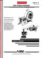
LN-9 Wire Feeder
November, 1996
For use with machines having Code Numbers: 9134, 9842, 9958, 10316, 10327
Return to Master TOC
View Safety Info
View Safety Info
Safety Depends on You
Return to Master TOC
Return to Master TOC
RETURN TO MAIN INDEX
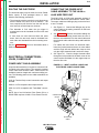
Lincoln arc welding equipment
is designed and built with safety
in mind. However, your overall
safety can be increased by
proper installation. . . and
thoughtful operation on your
part. DO NOT INSTALL,
OPERATE OR REPAIR THIS
EQUIPMENT WITHOUT READING THIS MANUAL AND THE
SAFETY PRECAUTIONS CONTAINED THROUGHOUT. And,
most importantly, think before
you act and be careful.
View Safety Info
Return to Master TOC
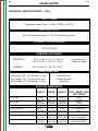
SERVICE MANUAL
World’s Leader in Welding and Cutting Products
Premier Manufacturer of Industrial Motors
Sales and Service through subsidiaries and Distributors Worldwide
22801 St. Clair Ave. Cleveland, Ohio 44117-1199 U.S.A. Tel. (216) 481-8100
Return to Master TOC
i
i
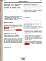
SAFETY
WARNING
CALIFORNIA PROPOSITION 65 WARNINGS
Diesel engine exhaust and some of its constituents
are known to the State of California to cause cancer, birth defects, and other reproductive harm.
The Above For Diesel Engines
The engine exhaust from this product contains
chemicals known to the State of California to cause
cancer, birth defects, or other reproductive harm.
The Above For Gasoline Engines
ARC WELDING CAN BE HAZARDOUS. PROTECT YOURSELF AND OTHERS FROM POSSIBLE SERIOUS INJURY OR DEATH.
KEEP CHILDREN AWAY. PACEMAKER WEARERS SHOULD CONSULT WITH THEIR DOCTOR BEFORE OPERATING.
Return to Master TOC
Return to Master TOC
Read and understand the following safety highlights. For additional safety information, it is strongly recommended that you
purchase a copy of “Safety in Welding & Cutting - ANSI Standard Z49.1” from the American Welding Society, P.O. Box 351040,
Miami, Florida 33135 or CSA Standard W117.2-1974. A Free copy of “Arc Welding Safety” booklet E205 is available from the
Lincoln Electric Company, 22801 St. Clair Avenue, Cleveland, Ohio 44117-1199.
BE SURE THAT ALL INSTALLATION, OPERATION, MAINTENANCE AND REPAIR PROCEDURES ARE
PERFORMED ONLY BY QUALIFIED INDIVIDUALS.
FOR ENGINE
powered equipment.
1.h. To avoid scalding, do not remove the
radiator pressure cap when the engine is
hot.
1.a. Turn the engine off before troubleshooting and maintenance
work unless the maintenance work requires it to be running.
____________________________________________________
1.b.Operate engines in open, well-ventilated
areas or vent the engine exhaust fumes
outdoors.
____________________________________________________
1.c. Do not add the fuel near an open flame welding arc or when the engine is running. Stop
the engine and allow it to cool before refueling to prevent spilled fuel from vaporizing on
contact with hot engine parts and igniting. Do
not spill fuel when filling tank. If fuel is spilled,
wipe it up and do not start engine until fumes
have been eliminated.
____________________________________________________
1.d. Keep all equipment safety guards, covers
and devices in position and in good
repair.Keep hands, hair, clothing and tools
away from V-belts, gears, fans and all other
moving parts when starting, operating or
repairing equipment.
Return to Master TOC
____________________________________________________
1.e. In some cases it may be necessary to remove safety
guards to perform required maintenance. Remove
guards only when necessary and replace them when the
maintenance requiring their removal is complete.
Always use the greatest care when working near moving
parts.
___________________________________________________
1.f. Do not put your hands near the engine fan. Do not attempt to
override the governor or idler by pushing on the throttle control rods while the engine is running.
___________________________________________________
1.g. To prevent accidentally starting gasoline engines while
turning the engine or welding generator during maintenance
work, disconnect the spark plug wires, distributor cap or
magneto wire as appropriate.
ELECTRIC AND
MAGNETIC FIELDS
may be dangerous
2.a. Electric current flowing through any conductor causes
localized Electric and Magnetic Fields (EMF). Welding
current creates EMF fields around welding cables and
welding machines
2.b. EMF fields may interfere with some pacemakers, and
welders having a pacemaker should consult their physician
before welding.
2.c. Exposure to EMF fields in welding may have other health
effects which are now not known.
2.d. All welders should use the following procedures in order to
minimize exposure to EMF fields from the welding circuit:
2.d.1. Route the electrode and work cables together - Secure
them with tape when possible.
2.d.2. Never coil the electrode lead around your body.
2.d.3. Do not place your body between the electrode and
work cables. If the electrode cable is on your right
side, the work cable should also be on your right side.
2.d.4. Connect the work cable to the workpiece as close as
possible to the area being welded.
2.d.5. Do not work next to welding power source.
LN-9 Wire Feeder
Return to Master TOC
Return to Master TOC
ii
SAFETY
ELECTRIC SHOCK can kill.
ARC RAYS can burn.
3.a. The electrode and work (or ground) circuits
are electrically “hot” when the welder is on.
Do not touch these “hot” parts with your bare
skin or wet clothing. Wear dry, hole-free
gloves to insulate hands.
4.a. Use a shield with the proper filter and cover
plates to protect your eyes from sparks and
the rays of the arc when welding or observing
open arc welding. Headshield and filter lens
should conform to ANSI Z87. I standards.
3.b. Insulate yourself from work and ground using dry insulation.
Make certain the insulation is large enough to cover your full
area of physical contact with work and ground.
4.b. Use suitable clothing made from durable flame-resistant
material to protect your skin and that of your helpers from
the arc rays.
In addition to the normal safety precautions, if welding
must be performed under electrically hazardous
conditions (in damp locations or while wearing wet
clothing; on metal structures such as floors, gratings or
scaffolds; when in cramped positions such as sitting,
kneeling or lying, if there is a high risk of unavoidable or
accidental contact with the workpiece or ground) use
the following equipment:
• Semiautomatic DC Constant Voltage (Wire) Welder.
• DC Manual (Stick) Welder.
• AC Welder with Reduced Voltage Control.
4.c. Protect other nearby personnel with suitable, non-flammable
screening and/or warn them not to watch the arc nor expose
themselves to the arc rays or to hot spatter or metal.
3.c. In semiautomatic or automatic wire welding, the electrode,
electrode reel, welding head, nozzle or semiautomatic
welding gun are also electrically “hot”.
3.d. Always be sure the work cable makes a good electrical
connection with the metal being welded. The connection
should be as close as possible to the area being welded.
3.e. Ground the work or metal to be welded to a good electrical
(earth) ground.
3.f. Maintain the electrode holder, work clamp, welding cable and
welding machine in good, safe operating condition. Replace
damaged insulation.
Return to Master TOC
ii
3.g. Never dip the electrode in water for cooling.
3.h. Never simultaneously touch electrically “hot” parts of
electrode holders connected to two welders because voltage
between the two can be the total of the open circuit voltage
of both welders.
3.i. When working above floor level, use a safety belt to protect
yourself from a fall should you get a shock.
3.j. Also see Items 6.c. and 8.
FUMES AND GASES
can be dangerous.
5.a. Welding may produce fumes and gases
hazardous to health. Avoid breathing these
fumes and gases.When welding, keep
your head out of the fume. Use enough
ventilation and/or exhaust at the arc to keep
fumes and gases away from the breathing zone. When
welding with electrodes which require special
ventilation such as stainless or hard facing (see
instructions on container or MSDS) or on lead or
cadmium plated steel and other metals or coatings
which produce highly toxic fumes, keep exposure as
low as possible and below Threshold Limit Values (TLV)
using local exhaust or mechanical ventilation. In
confined spaces or in some circumstances, outdoors, a
respirator may be required. Additional precautions are
also required when welding on galvanized steel.
5.b. Do not weld in locations near chlorinated hydrocarbon vapors
coming from degreasing, cleaning or spraying operations.
The heat and rays of the arc can react with solvent vapors to
form phosgene, a highly toxic gas, and other irritating
products.
5.c. Shielding gases used for arc welding can displace air and
cause injury or death. Always use enough ventilation,
especially in confined areas, to insure breathing air is safe.
5.d. Read and understand the manufacturer’s instructions for this
equipment and the consumables to be used, including the
material safety data sheet (MSDS) and follow your
employer’s safety practices. MSDS forms are available from
your welding distributor or from the manufacturer.
Return to Master TOC
5.e. Also see item 1.b.
LN-9 Wire Feeder
Return to Master TOC
iii
SAFETY
WELDING SPARKS can
cause fire or explosion.
6.a. Remove fire hazards from the welding area.
If this is not possible, cover them to prevent
the welding sparks from starting a fire.
Remember that welding sparks and hot
materials from welding can easily go through small cracks
and openings to adjacent areas. Avoid welding near
hydraulic lines. Have a fire extinguisher readily available.
6.b. Where compressed gases are to be used at the job site,
special precautions should be used to prevent hazardous
situations. Refer to “Safety in Welding and Cutting” (ANSI
Standard Z49.1) and the operating information for the
equipment being used.
Return to Master TOC
6.c. When not welding, make certain no part of the electrode
circuit is touching the work or ground. Accidental contact can
cause overheating and create a fire hazard.
6.d. Do not heat, cut or weld tanks, drums or containers until the
proper steps have been taken to insure that such procedures
will not cause flammable or toxic vapors from substances
inside. They can cause an explosion even though they have
been “cleaned”. For information, purchase “Recommended
Safe Practices for the Preparation for Welding and Cutting of
Containers and Piping That Have Held Hazardous
Substances”, AWS F4.1 from the American Welding Society
(see address above).
6.e. Vent hollow castings or containers before heating, cutting or
welding. They may explode.
Return to Master TOC
6.f. Sparks and spatter are thrown from the welding arc. Wear oil
free protective garments such as leather gloves, heavy shirt,
cuffless trousers, high shoes and a cap over your hair. Wear
ear plugs when welding out of position or in confined places.
Always wear safety glasses with side shields when in a
welding area.
Return to Master TOC
iii
6.g. Connect the work cable to the work as close to the welding
area as practical. Work cables connected to the building
framework or other locations away from the welding area
increase the possibility of the welding current passing
through lifting chains, crane cables or other alternate circuits.
This can create fire hazards or overheat lifting chains or
cables until they fail.
6.h. Also see item 1.c.
CYLINDER may explode
if damaged.
7.a. Use only compressed gas cylinders
containing the correct shielding gas for the
process used and properly operating
regulators designed for the gas and
pressure used. All hoses, fittings, etc. should be suitable for
the application and maintained in good condition.
7.b. Always keep cylinders in an upright position securely
chained to an undercarriage or fixed support.
7.c. Cylinders should be located:
• Away from areas where they may be struck or subjected to
physical damage.
• A safe distance from arc welding or cutting operations and
any other source of heat, sparks, or flame.
7.d. Never allow the electrode, electrode holder or any other
electrically “hot” parts to touch a cylinder.
7.e. Keep your head and face away from the cylinder valve outlet
when opening the cylinder valve.
7.f. Valve protection caps should always be in place and hand
tight except when the cylinder is in use or connected for
use.
7.g. Read and follow the instructions on compressed gas
cylinders, associated equipment, and CGA publication P-l,
“Precautions for Safe Handling of Compressed Gases in
Cylinders,” available from the Compressed Gas Association
1235 Jefferson Davis Highway, Arlington, VA 22202.
FOR ELECTRICALLY
powered equipment.
8.a. Turn off input power using the disconnect
switch at the fuse box before working on
the equipment.
8.b. Install equipment in accordance with the U.S. National
Electrical Code, all local codes and the manufacturer’s
recommendations.
8.c. Ground the equipment in accordance with the U.S. National
Electrical Code and the manufacturer’s recommendations.
LN-9 Wire Feeder
Return to Master TOC
iv
SAFETY
PRÉCAUTIONS DE SÛRETÉ
Pour votre propre protection lire et observer toutes les instructions
et les précautions de sûreté specifiques qui parraissent dans ce
manuel aussi bien que les précautions de sûreté générales suivantes:
Sûreté Pour Soudage A L’Arc
1.
Protegez-vous contre la secousse électrique:
a.
Return to Master TOC
b.
Les circuits à l’électrode et à la piéce sont sous tension
quand la machine à souder est en marche. Eviter toujours tout contact entre les parties sous tension et la
peau nue ou les vétements mouillés. Porter des gants
secs et sans trous pour isoler les mains.
Faire trés attention de bien s’isoler de la masse quand on
soude dans des endroits humides, ou sur un plancher
metallique ou des grilles metalliques, principalement
dans les positions assis ou couché pour lesquelles une
grande partie du corps peut être en contact avec la
masse.
c.
Maintenir le porte-électrode, la pince de masse, le câble
de soudage et la machine à souder en bon et sûr état
defonctionnement.
d.
Ne jamais plonger le porte-électrode dans l’eau pour le
refroidir.
e.
Ne jamais toucher simultanément les parties sous tension des porte-électrodes connectés à deux machines à
souder parce que la tension entre les deux pinces peut
être le total de la tension à vide des deux machines.
2.
Dans le cas de travail au dessus du niveau du sol, se protéger
contre les chutes dans le cas ou on recoit un choc. Ne jamais
enroule le câble-électrode autour de n’importe quelle partie du
corps.
3.
Un coup d’arc peut être plus sévère qu’un coup de soliel,
donc:
Return to Master TOC
Return to Master TOC
iv
a.
Utiliser un bon masque avec un verre filtrant approprié
ainsi qu’un verre blanc afin de se protéger les yeux du
rayonnement de l’arc et des projections quand on soude
ou quand on regarde l’arc.
b.
Porter des vêtements convenables afin de protéger la
peau de soudeur et des aides contre le rayonnementde
l’arc.
c.
Protéger l’autre personnel travaillant à proximité au
soudage à l’aide d’écrans appropriés et non-inflammables.
4.
Des gouttes de laiter en fusion sont émises de l’arc de
soudage. Se protéger avec es vêtements de protection libres
de l’huile, tels que les gants en cuir, chemise épaisse, pantalons sans revers, et chaussures montantes.
5.
Toujours porter des lunettes de sécurité dans la zone de
soudage. Utiliser des lunettes avec écrans lateraux dans les
zones où l’on pique le laitier.
6.
Eloigner les matériaux inflammables ou les recouvrir afin de
prévenir ttout risque d’incendie dû étincelles.
7. Quand on ne soude pas, poser la pince à une endroit isolé
de la masse. Un court-circuit accidental peut provoquer un
échauffement et un risque d’incendie.
8. S’assurer que la masse est connectée le plus prés possible
de la zone de travail qu’il est pratique de la faire. Si on place
la masse sur la charpente de la construction ou d’autres
endroits éloignés de la zone de travail, on augmente le
risque de voir passer le courant de soudage par les chaines
de levage, câbles de grue, ou atres circuits. Cela peut
provoquer des risques d’incendie ou d’echauffement des
chaines et des câbles jusqu’à ce qu’ils se rompent.
9. Assurer une ventilation suffisante dans la zone de soudage.
Ceci est particuliérement important pour le soudage de tôles
galvanisées plombées, ou cadmiées ou tout autre métal qui
produit des fumées toxiques.
10. Ne pas souder en présence de vapeurs de chlore provenant
d’opéerations de dégraissage, nettoyage ou pistolage. La
chaleur ou les rayons de l’arc peuvent réagir avec les
vapeurs du solvant pour produire du phosgéne (gas fortement roxique) ou autres produits irritants.
PRÉCAUTIONS DE SÛRETÉ POUR LES
MACHINES À SOUDER À TRANSFORMATEUR ET À REDRESSEUR
1.
Relier à la terre le chassis du poste conformement au code
de l’électricité et aux recommendations du fabricant. Le dispositif de montage ou la piece à souder doit être branché à
une bonne mise à la terre.
2.
Autant que possible, l’installation et l’entretien du poste
seront effectués par un électricien qualifié.
3.
Avant de faires des travaux à l’interieur de poste, la
debrancher à l’interrupteur à la boite de fusibles.
4.
Garder tous les couvercles et dispostifis de sûreté à leur
place.
LN-9 Wire Feeder
v
v
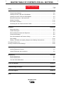
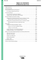
MASTER TABLE OF CONTENTS FOR ALL SECTIONS
RETURN TO MAIN INDEX
Page
Safety .................................................................................................................................................i-iv
Installation.............................................................................................................................Section A
Technical Specifications ..............................................................................................................A-2
Installing the LN-9 2-Roll and 4-Roll Models ..............................................................................A-3
Installing the LN-9F 2-Roll and 4-Roll Models ............................................................................A-3
Electrical Connections - LN-9 and LN-9F ...................................................................................A-4
Machine Grounding...................................................................................................................A-12
Work Cable Connection ............................................................................................................A-12
Connecting the Gun Cable to the Wire Feeder ........................................................................A-13
Operation...............................................................................................................................Section B
Safety Instructions.......................................................................................................................B-2
General Description ....................................................................................................................B-3
Recommended Processes and Equipment.................................................................................B-3
Controls and Settings..................................................................................................................B-4
Drive Roll Installation and Pressure Setting ...............................................................................B-9
Wire Loading .............................................................................................................................B-14
Making a Test Weld and Adjusting Response and Starting Characteristics .............................B-18
Procedure at End of Coil .................................................................................................................B-20
Security of Weld Procedure Settings...............................................................................................B-20
Accessories ..........................................................................................................................Section C
Auxiliary Equipment Contacts .....................................................................................................C-2
Optional Equipment and Accessories .........................................................................................C-2
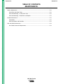
Maintenance ..........................................................................................................................Section D
Routine Maintenance ..................................................................................................................D-2
Periodic Maintenance .................................................................................................................D-2
Gun and Cable Maintenance ......................................................................................................D-3
Theory of Operation .............................................................................................................Section E
Troubleshooting and Repair ................................................................................................Section F
Electrical Diagrams ..............................................................................................................Section G
Parts ..............................................................................................................................................P-127
LN-9 Wire Feeder
Return to Master TOC
Section A-1
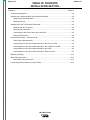
TABLE OF CONTENTS
- INSTALLATION SECTION -
Section A-1
Installation ................................................................................................................................Section A
Technical Specifications ..............................................................................................................A-2
Installing the LN-9N and LN-9S 2-Roll and 4-Roll Models .........................................................A-3
Attaching the Wire Reel Stand .............................................................................................A-3
Mounting the Unit .................................................................................................................A-3
Installing the LN-9F 2-Roll and 4-Roll Models ............................................................................A-3
Mounting the Wire Feed Unit................................................................................................A-3
Mounting the Control Box .....................................................................................................A-3
Connecting the Wire Feed Unit to the Control Box ..............................................................A-3
Return to Master TOC
Routing the Electrode ...........................................................................................................A-4
Electrical Connections – LN-9 and LN-9F ..................................................................................A-4
Power Input Cable Assembly................................................................................................A-4
Connecting the Power Input Cable Assembly to the LN-9 or LN-9S ...................................A-4
Connecting the Power Input Cable Assembly to the LN-9NE or LN-9SE ............................A-5
Connecting the Power Input Cable Assembly to the LN-9F.................................................A-6
Connecting the Power Input Cable Assembly to Power Sources ........................................A-7
Machine grounding....................................................................................................................A-12
Work Cable Connection ............................................................................................................A-12
Direct Work Cable Connection ...........................................................................................A-12
Return to Master TOC
Return to Master TOC
Connecting the Gun Cable to the Wire Feeder ........................................................................A-13
LN-9 Wire Feeder
Return to Master TOC
Return to Section TOC
A-2
A-2
INSTALLATION
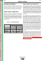
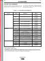
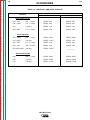
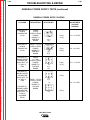
TECHNICAL SPECIFICATIONS — LN-9
INPUT POWER
Supplied by power source: 115 VAC, 50/60 Hz., 350 VA
WIRE FEED SPEED
Return to Master TOC
Return to Master TOC
Return to Section TOC
Return to Section TOC
50 to 600 inches per minute (1.27 to 15.2 meters per minute)
VOLTAGE CONTROL RANGE
12.0 TO 60.0 VDC
TEMPERATURE RANGE
OPERATION:
- 20o C to +40o C (- 4o F to +104o F)
- 40o C to +40o C (- 40o F to +104o F)
STORAGE:
- 40o C to +85o C (- 40o F to +185o F)
WIRE DIAMETERS
.030 through 3/32" (0.8 through 2.4 mm)
.045 through .120" (1.2 through 3.0 mm)
.035 through 1/16" (0.9 through 1.6 mm)
LN-9 (4 Roll)
Return to Master TOC
Solid Electrode
Cored Electrode
Aluminum
PHYSICAL DIMENSIONS
LN-9 (2 Roll)
Return to Section TOC
Recommended
Maximum Rated
LN-9F Control Box
LN-9F Wire Drive (2 Roll)
LN-9F Wire Drive (4 Roll)
LENGTH
WIDTH
HEIGHT
TOTAL WEIGHT LESS
ELECTRODE
12.15 in.
(308.4 mm)
12.15 in.
(308.4 mm)
11.56 in.
(293.4 mm)
11.56 in.
(293.4 mm)
12.19 in.
(309.4 mm)
12.19 in.
(309.4 mm)
36 lbs
(16.3 kg)
38 lbs
(17.2 kg)
10.4 in.
(264 mm)
6.17 in.
(156.6 mm)
11.26 in.
(293.4 mm)
See Total Weight
Below
8.79 in.
(223.3 mm)
8.79 in.
(223.3 mm)
9.77 in.
(248.2 mm)
9.77 in.
(248.2 mm)
13.76 in.
(349.5 mm)
13.76 in.
(349.5 mm)
67 lbs (30.4 kg)
Total Package Weight
72 lbs (32.7 kg)
Total Package Weight
Return to Master TOC
Return to Section TOC
A-3
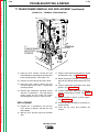
INSTALLATION
INSTALLING THE LN-9N and LN-9S
2-ROLL AND 4-ROLL MODELS
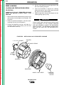
ATTACHING THE WIRE REEL STAND
Both 2-Roll and 4-Roll LN-9 model wire feeders are
shipped without a wire reel stand. The screws and
washers for mounting a wire reel stand are included
with the LN-9 (fastened in their respective mounting
holes). To attach a stand:
1. Remove the three 3/8" hex screws from the back of
the wire feed unit.
Return to Master TOC
Return to Section TOC
2. Place the wire reel stand mounting bracket in position against the back of the wire feed unit.
3. Replace and tighten the screws. The long screw
and plain washer go into the top hole.
Return to Section TOC
Return to Master TOC
Return to Master TOC
MOUNTING THE CONTROL BOX
The same control box is used for both the 2-Roll and 4Roll wire feed unit. It contains two keyhole slots and
one slot for mounting. Mount the box at some convenient location close to the wire feed unit. This will
enable the 16-foot control cable assembly supplied
with both the LN-9F 2-Roll and 4-Roll to reach between
the control box and the wire feed unit.
1. Drill the required holes in the mounting surface.
Partially install 1/4-20 screws.
2. Open the control box door by removing the two door
screws.
3. Mount the box.
4. Tighten the screws.
5. Close the control box door and replace the door
screws.
MOUNTING THE UNIT
LN-9N model wire feeders can be mounted directly on
top of their power source as long as it is secure and
level. When portability is required, the LN-9 can be
mounted on a K163 undercarriage See the
Accessories section for details.
A K178-1 swivel platform is available for mounting the
LN-9 to the power source. See the Accessories section for details.
Return to Section TOC
A-3
INSTALLING THE LN-9F
2-ROLL AND 4-ROLL MODELS
CONNECTING THE WIRE FEED UNIT TO
THE CONTROL BOX
Both the LN-9F 2-Roll and 4-Roll include the same 16
ft. control and electrode cable assembly. Connect the
wire feed unit to the control box as follows:
1. Make certain the cables are protected from any
sharp corners that may damage their jackets.
Mount the cable assembly along the boom so the
end with the female amphenol connector pins is at
the wire feed unit.
2. Connect the cable connectors to the receptacles on
the back of the wire feed unit connection box.
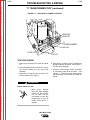
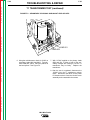
MOUNTING THE WIRE FEED UNIT
Mount the wire feed unit by means of the insulated
mounting bracket attached to the bottom of the gearbox. The gearbox assembly is electrically "hot" when
the gun trigger is pressed. Therefore, make certain the
gearbox does not come in contact with the structure on
which the unit is mounted. The wire feed unit should
be mounted so that the drive rolls are in a vertical plane
so dirt will not collect in the drive roll area. Position the
mechanism so it will point down at about a 45o angle so
the wire feed gun cable will not be bent sharply as it
comes from the unit.
3. At the same end, connect the electrode lead to the
connection stud of the copper strap along the side
of the wire feed unit.
4. At the control box end, connect the amphenol connectors of the control cable to the mating MS-type
receptacles on the bottom of the control box. (See
Figure A.4, later in this section, for the location of
this connection.)
LN-9 Wire Feeder
Return to Master TOC
Return to Section TOC
A-4
INSTALLATION
ROUTING THE ELECTRODE
The electrode supply may be either from reels, ReadiReels, spools, or bulk packaged drums or reels.
Observe the following precautions:
• The electrode must be routed to the wire feed unit so
that the bends in the wire are at a minimum. The
force required to pull the wire from the reel into the
wire feed unit must be kept at a minimum.
Return to Master TOC
• The electrode is "hot" when the gun trigger is
pressed and must be insulated from the boom and
structure.
Return to Section TOC
A-4
• If more than one wire feed unit share the same
boom, their wire and reels must be insulated from
each other and insulated from their mounting structure.
See the Accessories section for information about a
K299 wire reel assembly.
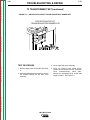
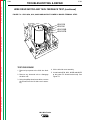
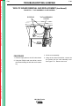
CONNECTING THE POWER INPUT
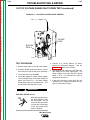
CABLE ASSEMBLY TO THE LN-9N or
LN-9S WIRE FEED UNIT
The K196, K595, or K596 cable assembly consists of
an electrode cable and multiconductor control cable.
The control cable has a MS-type plug on the wire feeder end. To install:
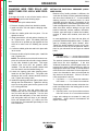
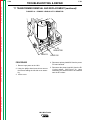
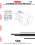
1. See Figure A.1. Connect the MS-type plug of the
control cable to the mating connector on the back
of the wire feeder.
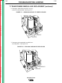
2. See Figure A.2. Remove the screws holding the
cable strain relief clamp located near the rear of
the wire reel stand base. Put the control cable and
the electrode cable under the clamp and install the
screws.
For cables with more than one electrode cable,
leave the junction between the two or more cables
and the single 4/0 stub behind the clamp so that
only the single electrode lead is under the clamp.
3. See Figure A.1. Pass the single electrode cable
through the hole provided in the back corner of the
control section and fasten it to the copper strap on
the wire drive unit.
ELECTRICAL CONNECTIONS LN-9N, S AND LN-9F
Return to Master TOC
Return to Section TOC
POWER INPUT CABLE ASSEMBLY
A special cable assembly is required to connect all LN9 models to the power source. The assembly includes
control cable and electrode cable. Various sizes are
available, based on length and maximum welding current. The following power source cable assemblies are
available:
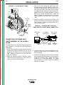
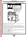
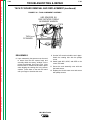
FIGURE A.1 – INPUT CONTROL CABLE AND
ELECTRODE CABLE CONNECTIONS
K196 for Terminal Strip control connection and output
terminal.
K595 for 14-Pin receptacle and output terminal.
K596 for 14-Pin receptacle and "Twist-Mate" connection.
NOTE: Use of an LN-9 with a Pulse Power 500 or a
DC650 PRO requires a K442-1 Pulse Power Filter Kit.
CONDUCTOR
BLOCK
Return to Master TOC
Return to Section TOC
CONTROL
CABLE
ELECTRODE
CABLE
LN-9 Wire Feeder
Return to Master TOC
Return to Section TOC
A-5
INSTALLATION
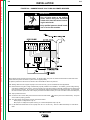
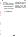
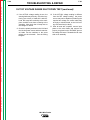
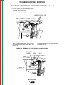
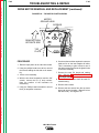
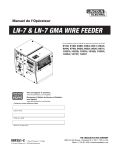
FIGURE A.2 – STRAIN RELIEF CLAMP
Return to Master TOC
Return to Section TOC
CONTROL
CABLE
STRAIN
RELIEF
CLAMP
Return to Section TOC
Return to Master TOC
Return to Master TOC
3. Remove the screws holding the cable clamp located near the rear of the wire reel base. Put the control cable and the electrode cable under the clamp
and install the screws. (On cables with more than
one electrode cable, leave the junction between the
cables and the single 4/0 stub behind the clamp so
that only the single electrode lead is under the
clamp.) Connect the electrode cable of the input
cable assembly to the brass block on the hand
crank.
4. Insert the connector on the conductor sheath of the
extension assembly into the brass block of the hand
crank assembly. Tighten the locking screw with a
3/16 hex allen wrench.
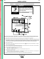
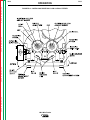
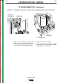
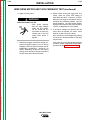
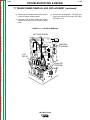
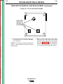
FIGURE A.3 – LN-9NE/SE INPUT CONTROL
CABLE AND ELECTRODE CABLE CONNECTIONS
WIRE DRIVE
UNIT
POLARIZED
CONNECTOR
INPUT CABLE
ASSEMBLY
ELECTRODE
CABLE
CONNECTING THE POWER INPUT
CABLE ASSEMBLY TO THE LN-9NE or
LN-9SE
Return to Section TOC
A-5
The hand crank drive rolls will feed all the wires used
on the extension. The rolls have been stenciled for
identification.
1. Position the extension assembly cable so that the
amphenol plug with the threads on its O.D. can be
attached to the amphenol end of the power input
cable. Attach the opposite end to the wire drive
unit. See Figure A.3.
2. Attach the amphenol extension assembly control
cable (the one with threads on its O.D.) to the connector on the input cable assembly.
EXTENSION
CABLE
BRASS
BLOCK
HAND
CRANK
WIRE REEL
BASE
5. At the wire drive unit, connect the amphenol of the
extension control cable to the receptacle on the
back of the LN-9.
6. Remove the ingoing guide tube from the rear brass
block and then plug the connector of the conductor
sheath into the brass block. Tighten the locking
screw with a 3/16" hex allen wrench. The guide
tube removed is not used when the extension
assembly is installed.
LN-9 Wire Feeder
Return to Master TOC
Return to Master TOC
Return to Master TOC
Return to Master TOC
Return to Section TOC
Return to Section TOC
Return to Section TOC
Return to Section TOC
A-6
A-6
INSTALLATION
7. If using welding currents over 450 amperes, connect a length of 1/0 cable between the brass block
on the hand crank and the input strap located in the
wire drive unit. Tape this cable to the extension
assembly. Proper cable lengths are as follows:
22-1/2 ft. extension
45 ft. extension
26’ M5906-106
46’ M5906-104
8. A handle is provided and is mounted to the wire
drive unit in the following manner:
Remove the two self-tapping screws that hold the
hinge pin in captivity. Push the hinge pin out, leaving the covers intact. Place the handle into the
slots provided. Push the hinge pin back into the
assembly, making sure that the pin goes through
the holes in the handle. Put the two self-tapping
screws back into their respective positions and
tighten.
9. If the extension is being used with a K306 Wire
Reel Flux Tank Assembly, the hose attached to the
bottom of the flux tank may have to be shortened.
This hose is 64 feet long and is the correct length
for use with the 45 foot extension. If a 22-1/2 foot
extension is used, cut off 22-1/2 feet of the flux
hose to give the correct length of 41-1/2 feet. (The
conductor cable of the extension assembly is 221/2 feet long, tip to tip, and can be used to measure
the length cut off.) If you tape the flux hose to the
extension cables or the gun cable, be careful not to
deform or collapse the flux hose.
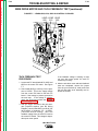
CONNECTING THE POWER INPUT
CABLE ASSEMBLY TO THE LN-9F
CONTROL BOX
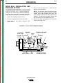
1. See Figure A.4. Connect the MS-type plug of the
K196, K595, or K596 control cable to the mating
MS-type connector on the bottom of the LN-9F control box.
2. Bolt the electrode lead from the power source to the
electrode lead to the wire feed unit using the nut
and bolt supplied. Insulate the connection with electrical tape.
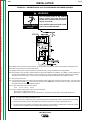
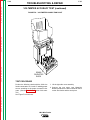
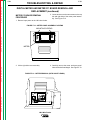
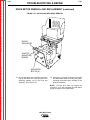
FIGURE A.4 – LN-9F CONTROL BOX
BOTTOM VIEW
CIRCUIT
BREAKER
GLP
RESET
4-PIN CONTROL CABLE
TACH FEEDBACK
CONNECTOR
9-PIN MS-TYPE CONNECTOR
INPUT CABLE TO POWER SOURCE
LN-9 Wire Feeder
14-PIN MS-TYPE CONNECTOR
CONTROL CABLE TO WIRE FEED HEAD
Return to Master TOC
Return to Section TOC
A-7
INSTALLATION
Depending on the power source and process you are
using, the jumpers on the LN-9 voltage board may
have to be changed. As shipped, the LN-9 is connected for use with the DC-250 DC-400, CV-400, CV-500-I
and DC-600. For other power sources, refer to the
appropriate connection diagram.
CONNECTING THE POWER INPUT
CABLE ASSEMBLY TO POWER
SOURCES
WARNING
Turn input supply power to the power source OFF
before connecting the LN-9 or LN-9F wire feeder.
NOTE: If you are using the Pulse Power 500 or DC650
Pro, the K442-1 Pulse Power Filter Kit must be
installed in the LN-9. See the instructions included with
the kit.
Return to Master TOC
Return to Section TOC
Connect to an appropriate Lincoln power source as follows:
1. If using a multipurpose source (such as the DC250, DC-400 and DC-600), be sure it is properly
set for the welding process being used. See the
topic "Making a Test Weld," in the Operation
section of this manual.
For terminal strip connections using the K196 power
input cable, connect the input cable to the power
source exactly as specified on the appropriate LN-9
model connection diagram:
Figure A.5 for DC-250, DC-400 and CV-400, CV-500 l
Figure A.6 for DC-600
Figure A.7 for DC-1000
Return to Section TOC
Return to Master TOC
Return to Master TOC
Figure A.8 for Pulse Power 500
Return to Section TOC
A-7
LN-9 Wire Feeder
Return to Master TOC
Return to Section TOC
A-8
INSTALLATION
A-8
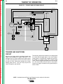
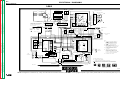
FIGURE A.5 – CONNECTION OF LN-9 TO DC-250, DC-400, AND CV/CVI POWER SOURCES
WARNING
• Turn off input power to the welding
power source using the disconnect
switch at the fuse box before connecting the wire feeder
Return to Section TOC
Return to Master TOC
Return to Section TOC
Return to Master TOC
ELECTRIC SHOCK • Only qualified persons should install,
use or service this machine.
can kill.
Above diagram shows electrode connected positive. To change polarity, turn power off, reverse the electrode and work leads at the
power source and position the switch on power source to proper polarity.
* Does not apply to DC-400 below code 9200 with polarity switch.
N.A. Welding cables must be of proper capacity for the current and duty cycle of immediate and future applications.
N.B. Extend lead #21 using #14 AWG or larger insulated wire physically suitable for the installation. An S16586-[ ] remote voltage
sensing work lead is available for this purpose. Connect it directly to the work piece keeping it electrically separate from the welding work lead circuit and connection. For convenience, this extended #21 lead should be taped to the welding work lead. (If the
length of work lead circuit is short, and connections can be expected to be reliable, then control cable lead #21 does not need to
be extended and can be directly connected to terminal #21 on the terminal strip. Note that this is not the preferred connection
because it adds error to the wire feeder voltmeter reading.)
Return to Master TOC
Return to Section TOC
N.C. Tape up bolted connection if lead #21 is extended.
N.D. Connect the control cable ground lead to the frame terminal marked
near the power source terminal strip. The power source
grounding terminal (marked
and located near the power source input power connections) must be properly connected to electrical ground per the power source operating manual.
N.F. The LN-9 voltage control jumpers must be connected as follows:
White jumper on voltage board to pin “S”.
Blue jumper on voltage board (later units only), or on start board (earlier units), to pin “B”.
*N.G. If lead #21 is to be connected to the terminal strip, connect to the #21 terminal that matches work polarity. This connection must
be changed whenever the electrode polarity is changed.
LN-9 Wire Feeder
Return to Master TOC
Return to Section TOC
A-9
A-9
INSTALLATION
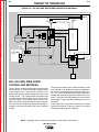
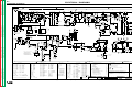
FIGURE A.6 – CONNECTION OF LN-9 TO DC-600 POWER SOURCES
WARNING
• Turn off input power to the welding
power source using the disconnect
switch at the fuse box before connecting the wire feeder
Return to Section TOC
Return to Master TOC
Return to Section TOC
Return to Master TOC
ELECTRIC SHOCK • Only qualified persons should install,
use or service this machine.
can kill.
Above diagram shows electrode connected positive. To change polarity, turn power off, reverse the electrode and work leads at the
power source and position the switch on power source to proper polarity.
For optimum performance with the LN-9, DC-600’s with codes 8288 and above are preferred.
N.B. Welding cables must be of proper capacity for the current and duty cycle of immediate and future applications.
N.C. Extend lead #21 using #14 or larger insulated wire physically suitable for the installation. An S16586-[ ] remote voltage sensing
work lead is available for this purpose. Connect it directly to the work piece keeping it electrically separate from the welding work
lead circuit and connection. For convenience, this extended #21 lead should be taped to the welding work lead. (This extended
#21 lead connection replaces the need to employ the remote work lead accessory on LN-9’s which have a direct work lead jack.)
Return to Master TOC
Return to Section TOC
N.D. Tape up bolted connection.
N.E. Connect the LN-9 control cable ground lead to the frame terminal marked
source must be properly grounded.
near the power source terminal strip. The power
N.G. The LN-9 voltage control jumpers must be connected as follows:
White jumper on voltage board to pin “S”.
Blue jumper on voltage board (Later units only) or on start board (Earlier units) to pin “B”.
N.H. For DC-600 Codes below 8200 connect a jumper from “N” to “P” on LN-9 only. There is no NPS terminal strip on codes above
8200.
LN-9 Wire Feeder
Return to Master TOC
Return to Section TOC
A-10
A-10
INSTALLATION
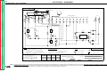
FIGURE A.7 – CONNECTION OF LN-9 TO DC-1000 POWER SOURCES
WARNING
• Turn off input power to the welding
power source using the disconnect
switch at the fuse box before connecting the wire feeder
Return to Section TOC
Return to Master TOC
Return to Section TOC
Return to Master TOC
ELECTRIC SHOCK • Only qualified persons should install,
use or service this machine.
can kill.
Above diagram shows electrode connected positive. To change polarity, turn power off, reverse the electrode and work leads at the
power source, position the positive - negative switch on power source to correspond to the polarity of the electrode cable connection.
N.A. Welding cables must be proper capacity for the current and duty cycle of immediate and future applications.
N.B. Extend lead #21 using #14 or larger insulated wire physically suitable for the installation. an S16586 remote voltage sensing work
lead is available for this purpose. Connect it directly to the work piece keeping it separate from the welding work cable connection
to work piece. For convenience, this extended #21 lead should be taped along the welding work cable. (This extended #21 lead
connection replaces the need to employ the remote work lead accessory on any LN-9 which has a direct work lead jack).
N.C. Tape up bolted connection.
N.D. Connect the LN-9 control cable ground lead to the frame terminal marked
source must be properly grounded.
near the power source terminal strip. The power
Return to Master TOC
Return to Section TOC
N.E. If using an older automatic control cable with leads #75, #76, #77; connect lead #75 to #75 on terminal strip, connect lead #76 to
#74 on terminal strip, connect lead #77 to #73 on terminal strip.
N.F. The LN-9 voltage control jumpers must be connected as follows:
White jumper on voltage board to pin “S”.
Blue jumper on voltage board (Later units only) or on start board (earlier units) to pin “B”.
N.G. Set the DC-1000 controls as follows:
Set the control switch to “output control remote”. For submerged arc processes, set the mode switch to “C.V. submerged arc”.
For open arc processes, set the mode switch to “C.V. Innershield”.
N.H. Alternative 500 amp positive terminal connection provided on DC-1000 models above code 9500 only.
LN-9 Wire Feeder
Return to Master TOC
Return to Section TOC
A-11
INSTALLATION
A-11
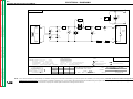
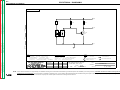
FIGURE A.8 – CONNECTION OF LN-9 TO PULSE POWER 500 POWER SOURCES
WARNING
• Turn off input power to the welding
power source using the disconnect
switch at the fuse box before connecting the wire feeder
Return to Master TOC
Return to Master TOC
Return to Section TOC
Return to Section TOC
ELECTRIC SHOCK • Only qualified persons should install,
use or service this machine.
can kill.
Above diagram shows electrode connected positive. To change polarity, turn power off, reverse the electrode and work leads at the
power source and properly set the feeder polarity switch.
N.A. Welding cables must be of proper capacity for the current and duty cycle of immediate and future applications.
N.B. Extend lead #21 using 14 AWG or larger insulated wire physically suitable for the installation. An S16586-[ ] remote voltage sensing work lead is available for this purpose. Connect it directly to the work piece keeping it electrically separate from the welding
work lead circuit and connection. For convenience, this extended #21 lead should be taped to the welding work lead.
N.C. Tape up bolted connection.
N.D. Connect the control cable ground lead to the frame terminal marked
near the power source terminal strip. The power source
grounding terminal (marked
and located near the power source input power connections) must be properly connected to electrical ground per the power source Operating Manual.
N.E. Connect control leads t terminal strip as follows:
LN-9:
A to 75 B to 77 C to 78
Return to Master TOC
Return to Section TOC
N.F. The LN-9 voltage control jumpers must be connected as follows:
White jumper on voltage board to pin “S”.
Blue jumper on voltage board is not connected to any pin. (Secure loose jumper clear of any possible interference.)
NOTE: For proper pulse welding operating with LN-9:
1. The LN-9 must have an L6084-3 (or higher superseding part number) voltage board installed. (Standard above code 9100.)
2. The Pulse Power Filter board must be installed and connected in the LN-9 per instructions provided with the kit.
3. The pulse current sensor assembly (with looped copper energizer) must be installed. (Standard above code 9100.) Feeder
conversion kits are available for all LN-9 model codes (below 9100 and above 9100).
LN-9 Wire Feeder
Return to Master TOC
Return to Section TOC
A-12
INSTALLATION
MACHINE GROUNDING
DIRECT WORK LEAD CONNECTION
LN-9 wire feeders are grounded to the power source
through the input cable. The power source grounding
cable must be properly connected to electrical ground.
See your power source operating manual for details.
Lincoln specified procedures give voltage readings
taken between the work and the gun cable brass connection block of the LN-9. To match these voltage readings, the connection diagrams show the #21 lead being
extended and connected directly to the work instead of
#21 on the power source terminal strip (or Dual
Process Kit terminal strip). This extended lead must be
connected directly to the work. When using a Dual
Process Kit, you must extend the lead individually for
each LN-9.
Return to Master TOC
Return to Master TOC
Return to Master TOC
Return to Section TOC
Return to Section TOC
WORK CABLE CONNECTION
Return to Section TOC
A-12
Connect a work lead of sufficient size and length
between the proper output terminal on the power
source and the work. See Table A-1. Be sure the connection to the work makes tight metal-to-metal electrical contact. Poor work lead connections can activate
the grounding lead protector and/or result in poor welding performance.
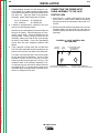
TABLE A.1 – WORK CABLE SIZES
Copper Work Cable Size, AWG
Current
60% Duty Cycle Up to 50' length 50'-100' Iength
300 Amps
0
000
400 Amps
00
0000
500 Amps
000
0000
600 Amps
000
Two 000
As an alternative, LN-9 models are provided with a
quick-connect terminal splice connection in the #21
lead between the input Amphenol connector of the
LN-9 and its polarity switch. See the LN-9 wiring diagram. This in-line connection consists of a red insulated male and female .250 x .032 terminal pair located in
the lead harness. It runs along the right side of the wire
feed motor inside the control section of the LN-9N and
S models and in the lead harness at the lower left corner of the control box (near the input Amphenol) of the
LN-9F models. You may also open this #21 lead and
connect your own direct work lead equipped with a
.250 x .032 female quick-connect terminal to the male
side of the splice. This direct work lead connection
must be tape insulated, strain-relieved, and routed outside the LN-9 control box to be connected directly to
the work.
With either direct work lead connection method, the
LN-9 regulates the power source to hold the arc voltage constant, even with voltage drops in the electrode
lead, work lead, or work lead connection. If the direct
work lead becomes disconnected from the work, the
LN-9 wire feeder will stop welding shortly after the arc
is struck. See the topic "Circuit Protection and
Automatic Shutdown" in the Operation section of
this manual.
LN-9 Wire Feeder
Return to Master TOC
Return to Master TOC
Return to Section TOC
Return to Section TOC
A-13
A-13
INSTALLATION
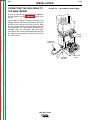
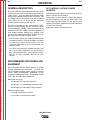
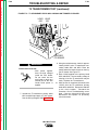
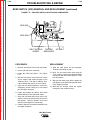
CONNECTING THE GUN CABLE TO
THE WIRE FEEDER
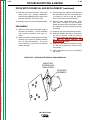
FIGURE A.9 – GUN CABLE CONNECTIONS
A variety of gun and cable assemblies are available for
the LN-9 models. See the Accessories section of this
manual.
Lay the cable out straight. Insert the connector on the
welding conductor cable into the brass conductor block
on the front of the wire drive unit. See Figure A.9. Make
sure the connector is fully seated and tighten the locking screws with a 3/16" Allen wrench or handscrew (if
provided). Keep this connection clean and bright.
Connect the control cable polarized Amphenol plug into
the mating 5-cavity receptacle on the front panel of the
wire drive section.
THUMBSCREW
AMPHENOL
CONNECTOR
Return to Section TOC
Return to Master TOC
Return to Section TOC
Return to Master TOC
GUN CABLE
ASSEMBLY
LN-9 Wire Feeder
CONDUCTOR
BLOCK
Return to Section TOC
Return to Master TOC
Return to Section TOC
Return to Master TOC
Return to Master TOC
Return to Section TOC
Return to Master TOC
Return to Section TOC
A-14
NOTES
LN-9 Wire Feeder
A-14
Return to Master TOC
Section B-1
Section B-1
TABLE OF CONTENTS
- OPERATION SECTION Operation .................................................................................................................................Section B
Safety Instructions.......................................................................................................................B-2
General Description ....................................................................................................................B-3
Recommended Processes and Equipment.................................................................................B-3
DC Constant Voltage Power Sources ..................................................................................B-3
Controls and Settings..................................................................................................................B-4
Circuit Protection and Automatic Shutdown .........................................................................B-7
Avoiding Ground Lead Protector (GLP) Activation ...............................................................B-7
Return to Master TOC
Drive Roll Installation and Pressure Setting ...............................................................................B-9
Changing Wire Feed Rolls and Guide Tubes for 2-Roll Wire Feeders ................................B-9
Setting the Idler Roll Spring Pressure (2-Roll Wire Drives) .........................................B-10
Changing Wire Feed Rolls and Guide Tubes for 4-Roll Wire Feeders...............................B-11
Setting the Idler Roll Pressure (4-Roll Wire Drives) .....................................................B-11
Wire Loading .............................................................................................................................B-14
Loading and Feeding Readi-Reels or Spools.....................................................................B-14
Loading a 22 to 30 lb. Readi-Reel Package ................................................................B-14
Loading a 15 to 30 lb. Spool ........................................................................................B-15
Loading 50 and 60 lb. Coils and Brake Adjustment ...........................................................B-16
Loading and Feeding 13-14 lb. Innershield Coils...............................................................B-17
Return to Master TOC
Return to Master TOC
Making a Test Weld and Adjusting Response and Starting Characteristics .............................B-18
Adjust the Power Source ....................................................................................................B-18
Adjust the LN-9 Controls ....................................................................................................B-19
Voltage Control Response..................................................................................................B-19
Starting Characteristics.......................................................................................................B-19
Making a Weld ....................................................................................................................B-20
Procedure at End of Coil...........................................................................................................B-20
Security of Weld Procedure Settings ........................................................................................B-20
LN-9 Wire Feeder
Return to Master TOC
Return to Section TOC
B-2
OPERATION
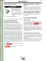
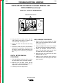
SAFETY INSTRUCTIONS
Read and understand this entire section of operating
instructions operating the machine.
WARNING
Return to Master TOC
Return to Section TOC
ELECTRIC SHOCK can kill.
• Do not touch electrically live parts such
as output terminals or internal wiring.
• Insulate yourself from the work and
ground.
• Always wear dry insulating gloves.
FUMES AND GASES can be
dangerous.
• Keep your head out of fumes.
Return to Section TOC
Return to Master TOC
Return to Section TOC
Return to Master TOC
• Use ventilation or exhaust to remove
fumes from breathing zone.
WELDING SPARKS can cause
fire or explosion.
• Keep flammable material away.
ARC RAYS can burn.
• Wear eye, ear, and body protection.
LN-9 Wire Feeder
B-2
Return to Master TOC
OPERATION
GENERAL DESCRIPTION
The LN-9 2-Roll and 4-Roll semiautomatic wire feeder
models feature the precise "set and forget" digital procedure control. They are designed to achieve higher
quality control and weld quality levels more easily. The
arc voltage and wire feed speed can be set on a digital
meter before the arc is struck and the procedure
remains precisely set day in and day out.
The wire feed speed and arc voltage can be "SET"
before or during welding, and the "ACTUAL" values
can be read during welding. Wire feed speed and arc
voltage will be held virtually constant regardless of
input voltage variation, feeding force, loading of the
power source, ambient temperature changes or a voltage drop in the electrode or ground circuit.
Return to Master TOC
Return to Section TOC
Return to Section TOC
B-3
DC CONSTANT VOLTAGE POWER
SOURCES
The following welding system power sources are available for use with all LN-9 models:
The Idealarc® DC-250, DC-400, CV-400 and DC-600
are recommended for use with any LN-9 model. The
Pulse Power 500 and DC650 Pro can also be used
with the LN-9 with the installation of the optional K4421 Pulse Power Filter Kit.
SAM power sources may also be used.
• Two drive rolls (driven) are used with calibrated idle
roll pressure setting. Rolls are available for feeding
.030 thru 3/32" solid and .045 through .120" flux
cored steel electrodes, as well as .035 through 1/16
aluminum wires.
• Four drive rolls (driven) are available and they work
on a "quick release"mechanism for easy access to
drive rolls and guide tubes. Drive roll kits are available for the same electrode sizes as the 2-roll
feeders.
Return to Master TOC
Return to Section TOC
RECOMMENDED PROCESSES AND
EQUIPMENT
When combined with the broad selection of quality
welding equipment and accessories, the LN-9 provides a versatile precision welding system to meet the
specific needs of Outershield®, Innershield® or submerged arc welding processes. The capabilities of the
LN-9 2-Roll and 4-Roll wire feeders are:
Rated wire size range:
.030 through 3/32" solid wire electrode.
.045 through .120" Outershield® cored electrode.
.062 through 7/64" lnnershield® cored electrode.
Rated wire speed range:
50 through 600 inches per minute.
Return to Master TOC
(1.27 through 15.2 meters per minute).
Return to Section TOC
B-3
LN-9 Wire Feeder
Return to Master TOC
Return to Master TOC
Return to Section TOC
Return to Section TOC
B-4
OPERATION
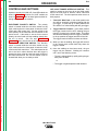
CONTROLS AND SETTINGS
Operator controls for LN-9N, NE, S and SE models are
shown in Figure B.1. Controls for LN-9F models are
shown in Figure B.2. Refer to these figures and the following descriptions of the controls.
ELECTRODE POLARITY SWITCH: The polarity
switch is located inside the wire drive section on the
LN-9 model and on the front panel of both the LN-9F
2-Roll and 4-Roll control box. Set the switch to the
same polarity as the electrode lead connection to the
power source. If the switch is not set for the correct
polarity, the wire feeder will stop welding shortly after
the arc is struck.
See the topic "Automatic
Shutdown" later in this section of the manual.
WIRE FEED DIRECTION SWITCH: The direction
switch is located inside the wire drive section on the
LN-9 model and on the front panel of both the LN-9F
2-Roll and 4-Roll control box. This switch permits the
wire to be fed in either direction when the trigger is
pressed or when using the cold inch switch feature of
the K202 Burnback kit. Be sure this switch is set for
forward feed when you are ready to weld.
B-4
HOT-COLD TRIGGER INTERLOCK SWITCH: This
switch is located on the front rail on the LN-9 model
and on the front panel of both the LN-9F 2-Roll and
4-Roll control box. The three-position switch serves a
dual purpose:
1. "Hot-Cold" Wire Feed - In the center position the
wire will be electrically cold when feeding with the
gun trigger. In either the up or down positions the
wire will be "hot" when feeding with the gun trigger.
2. Trigger Interlock Function - In the down position
the trigger interlock will be OFF, allowing the gun
trigger to function in the normal mode. This stops
wire feed and welding when the trigger is released.
In the up position the trigger interlock will be ON.
The trigger interlock feature functions as follows:
a) When you are not welding, the trigger will function
in the normal mode, which feeds only when the
trigger is closed.
b) Once the welding arc has been struck, the gun
trigger may be released. Welding will continue
until one of the following occurs:
• The arc is extinguished by quickly pulling the gun
away from the work.
or
Return to Section TOC
Return to Master TOC
Return to Section TOC
Return to Master TOC
• The trigger is again depressed and released.
LN-9 Wire Feeder
FIGURE B.1 – WIRE FEEDER CONTROLS FOR LN-9N, NE, S, SE
VOLTS
CONTROL
METER
READING
SWITCH
Return to Master TOC
Return to Section TOC
WIRE SPEED
CONTROL
DIGITAL
METER
SET-ACTUAL
PUSHBUTTON
CIRCUIT
BREAKER
Return to Section TOC
Return to Master TOC
Return to Master TOC
GROUNDING LEAD
PROTECTOR (GLP)
RESET SWITCH
Return to Section TOC
B-5
OPERATION
Return to Master TOC
Return to Section TOC
B-5
HOT-COLD
TRIGGER
INTERLOCK
SWITCH
ELECTRODE
POLARITY
SWITCH
WIRE-FEED
DIRECTION
SWITCH
LN-9 Wire Feeder
Return to Section TOC
Return to Master TOC
Return to Section TOC
Return to Master TOC
Return to Master TOC
Return to Section TOC
Return to Master TOC
Return to Section TOC
B-6
OPERATION
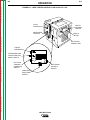
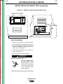
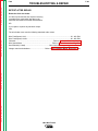
FIGURE B.2 – WIRE FEEDER CONTROLS FOR LN-9F
LN-9F CONTROL BOX BOTTOM VIEW
LN-9 Wire Feeder
B-6
Return to Master TOC
Return to Master TOC
Return to Master TOC
Return to Master TOC
Return to Section TOC
Return to Section TOC
Return to Section TOC
Return to Section TOC
B-7
OPERATION
CIRCUIT BREAKER AND GROUNDING LEAD PROTECTOR (GLP) RESET SWITCH: These protection
circuit devices are located on the front rail of the LN-9
model and bottom panel of the LN-9F models. See the
topic "Circuit Protection and Automatic Shutdown"
later in this section of the manual.
DIGITAL METER: A three-digit digital meter is provided to set and monitor the welding procedure. The arc
voltage is displayed in volts and the wire feed speed is
displayed in inches/minute or meters/minute.
METER READING SWITCH, VOLTS AND WIRE
SPEED CONTROLS: This four-position rotary switch
is located to the right of the digital meter on LN-9models and to the left of the digital meter on LN-9F models.
When set to the "Volts" position, the meter reads the
arc voltage setting as adjusted by the "Volts" control.
The rated setting range for all the LN-9 models is 12.0
to 60.0 volts.
The three "Wire Speed" positions include an English
position, for meter readings in inches/minute; and "LO"
and "HI" range metric positions for meter readings in
meters/minute. The wire feed speed setting is adjusted by the "Wire Speed" control. The rated setting
range for all the LN-9 models are 50 to 600
inches/minute (1.27 to 15.2 meters/minute).
When using metric meter readings, set the switch to
"LO" for more precise meter readings up to 393 in/min
(9.99 m/min.). For higher wire feed speeds, the "LO"
position will result in an over-range meter reading of
E.EE which indicates that the "HI" range, with single
decimal place resolution, should be used. Similarly,
EEE will be displayed on the English position if the setting exceeds 999 inches/minute.
The procedure adjustments can be made before or
during the weld. This feature permits the operator to
set the welding voltage and wire speed before welding
and without assistance.
Once set, the control circuits of the LN-9 will continuously monitor the volts and wire speed and correct any
deviation from the set value so there will be negligible
change.
Should the range of the power source output voltage be
such that the unit circuit cannot keep the arc voltage as
set, the unit will stop welding shortly after the arc is struck.
See the topic "Circuit Protection and Automatic
Shutdown" later in this section of the manual.
SET-ACTUAL PUSHBUTTON: After the weld has
been started, the ACTUAL voltage or wire speed can
be read by pressing the pushbutton to the left of the
meter. The METER READING switch must be set in
the desired position. When the pushbutton is not being
operated, the meter continues to read the SET value.
B-7
CIRCUIT PROTECTION AND AUTOMATIC
SHUTDOWN
CIRCUIT BREAKER
The circuit breaker normally trips only when excessive
loading in the wire feed cable or a defective motor or
control component causes an overload. After allowing
a minute for cooling, push in the circuit breaker button
and weld. If it trips again, be sure the wire feed cable
is clean and the proper size for the wire diameter being
fed. Also look for excessive drive roll pressure and
readjust if necessary. If the breaker still trips, look for
a defective electrical component. When the circuit
breaker is tripped, the digital meter is off and the trigger circuit will not operate.
POWER SUPPLY FUSE
The fuse on the PM power board inside the control box
protects the power supply circuit. When the fuse is
blown, the digital meter is off and the trigger circuit will
not operate.
VOLTAGE PC BOARD FUSE
The 1/8 amp fast-blow fuse protects the LN-9 circuitry
from damage that may result from a ground, or case,
faulted control lead. If this fuse blows, the LN-9 arc
voltage sensing lead circuit will be opened. See the
topic "Automatic Shutdown" below.
MOTOR THERMAL PROTECTION
The temperature sensing thermal protector mounted in
the motor frame opens the control circuit if the motor
overheats. Excessive loading and/or very rapid triggering may cause overheating. The thermal sensor
protects the motor without nuisance tripping. The thermal protector automatically resets itself after the motor
cools sufficiently (may take 10-15 minutes). Reset time
can be shortened by removing supply power to the LN9 and also by cooling the motor with an air hose or fan.
When the protector is tripped, the digital meter is lit but
there will be zero reading. The trigger circuit will not
operate.
AVOIDING GROUNDING LEAD PROTECTOR
(GLP) SHUTDOWN
The frames of all LN-9 wire feed units and drive motors
are grounded to the frame of the power source by a
lead in the control cable. An overload protector prevents welding current from damaging this lead if the
electrode circuit touches the wire feeder frame while
the gun trigger is pressed.
LN-9 Wire Feeder
Return to Master TOC
Return to Section TOC
B-8
OPERATION
If such a grounding lead fault occurs, the meter will still
be on and will be reading. The trigger circuit will not
operate, however. To release the circuit, press the
"GLP Reset" button. See Figure B.1 or B.2 for the
location of this button.
The following precautions are recommended to avoid
GLP shutdown:
• Do not allow the electrode to contact the case of the
wire feeder or uninsulated part of its wire reel stand
when the gun trigger is activated.
• Be sure that all work lead connections to the work
make tight metal-to-metal electrical contact.
Return to Master TOC
Return to Section TOC
• Do not allow excess input cable or work cable to be
placed closer than 3 feet to the wire feeder.
• Do not coil excess input cable assembly or use an
uncoiled assembly as shipped from the factory.
Instead, loop excess length back and forth in 3 to 6
foot straight lengths. Coiling the input cable results in
a transformer action between the electrode conductor
cable and ground lead in the multiconductor cable
and the ground lead in the multiconductor control
cable. This can cause current to flow in the ground
lead, which will falsely activate the GLP.
Return to Master TOC
Return to Section TOC
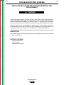
AUTOMATIC SHUTDOWN
If the LN-9 voltage control is unable to supply the SET
value of arc voltage while welding, the automatic shutdown circuit will activate. This protection circuit immediately returns the LN-9 control to idle state within a few
seconds after the arc voltage discrepancy occurs.
Typical causes for the activation of this protective shutdown circuit are as follows:
a) SET value of arc voltage is outside the power
source range.
b) Power source voltage control not set for REMOTE.
c) Misconnection of LN-9 control cable leads to
power source.
d) Incorrect weld polarity connections, or settings, at
the LN-9 or the power source.
Return to Master TOC
Return to Section TOC
e) Lost connection of LN-9 voltage sensing leads
(#67 and #21) between the arc and voltage control,
or a blown 1/8 amp fuse on the Voltage PC board.
Although out of range shutdown can occur with all
power sources when working with very low or very high
arc voltages, it is most likely to occur when using the
R3S models with somewhat limited voltage range of
B-8
the various taps. For instance, if the R3S-400 triangle
tap setting is for 31 volts, the range of control from the
remote circuit is approximately 7 volts, i.e., 27-1/2 to
34-1/2 volts at nominal input voltage. If the LN-9 controls are set for 29 volts and the input voltage to the
R3S goes up, it may not be possible for the LN-9 control circuit to hold the 29 volts. The welding will shut
down. By changing to the 27 volt triangle setting, the
range will be approximately 23-1/2 to 30-1/2 volts, and
at high input voltage there will be sufficient control to
hold the SET arc voltage. On these machines, if the
LN-9 stops welding, follow this procedure:
a) Move the LN-9 voltage set point 2 volts lower than
the desired procedure and make a test weld.
1. If the LN-9 still shuts down, go to Step b. below.
2. If the LN-9 keeps welding, change the R3S triangle setting to the next higher voltage and
reset the LN-9 set point to the desired procedure. R3S is now set properly unless there is
a significant change in input voltage. Skip the
following step.
b) Move the LN-9 voltage set point 2 volts higher than
the desired procedure and make a test weld.
1. If the LN-9 now keeps welding, change the
R3S triangle setting to the next lower voltage
and reset the LN-9 set point to the desired procedure. R3S is now set properly unless there
is a significant change in input voltage.
2. If the LN-9 still shuts down, refer to the paragraph below and the other possible causes
previously listed.
In some cases, it is also possible to hold the ACTUAL
button pressed while starting the arc. Before the LN-9
shuts down, the actual arc voltage can be read on the
digital meter. Comparing this reading to the SET reading will tell what change in the range controls of the
power source is required to supply the desired voltage.
Should the meter read zero, check the connections of
LN-9 sensing leads #21 and #67. Should the meter
read a minus (-) voltage, the polarity connections or
settings at the LN-9 or power source are wrong.
The same general procedure can be used on other
power sources. For example, if the LN-9 keeps shutting down and the other possible causes have been
checked, adjust the SET voltage higher and/or lower
than the desired voltage. Then you can determine
what change in the range controls of the power source
is required to supply the desired voltage.
LN-9 Wire Feeder
Return to Master TOC
Return to Section TOC
B-9
OPERATION
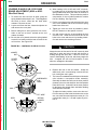
DRIVE ROLL INSTALLATION AND
PRESSURE SETTING
4. Remove idle roll shaft screw - install idle roll.
Replace screw and tighten.
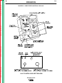
CHANGING WIRE FEED ROLLS AND GUIDE
TUBES FOR TWO-ROLL WIRE FEEDERS
NOTE: The Aluminum Wire Drive Roll Kits have
one-piece drive rolls and idle rolls with a larger
chamfer on one side, instead of gear teeth. This
larger chamfer side must face the gearbox when
installed. The side with the smaller chamfer and
wire size stencil must be installed facing out.
To change drive or idle rolls on a two-roll wire feeder,
refer to Figure B.3 and perform the following steps:
1. Loosen idle roll spring pressure screw.
2. Remove clamping collar from the drive shaft.
Return to Master TOC
Return to Master TOC
Return to Master TOC
Return to Section TOC
Return to Section TOC
3. Install drive roll and replace clamping collar.
Tighten screw.
Return to Section TOC
B-9
5. Remove the large ingoing guide from rear brass
block by loosening screw.
FIGURE B.3 – 2 ROLL WIRE FEED MECHANISM
OUTGOING
GUIDE TUBE
LOCKING
SCREW
CLAMPING
INGOING GUIDE TUBE
CLAMPING SCREW
COLLAR
DRIVE
ROLL
SCREW
SCREW
GUIDE
TUBE
INGOING
GUIDE
TUBE
IDLE ROLL
SHAFT SCREW
IDLE
ROLL
LN-9 Wire Feeder
IDLE ROLL SPRING
PRESSURE SCREW
Return to Master TOC
Return to Master TOC
Return to Master TOC
Return to Master TOC
Return to Section TOC
Return to Section TOC
Return to Section TOC
Return to Section TOC
B-10
OPERATION
6. Loosen the ingoing guide tube clamping screw.
Install the all steel guide tube through the rear
brass block. Tighten the locking screw.
7. Replace the large ingoing guide tube into rear
brass block.
8. Install the outgoing guide tube with its plastic insert
through front brass block. Tighten the locking
screw so its dog point goes into the groove in the
O.D. of the guide tube.
NOTE: The drive rolls and guide tubes are
stamped with the wire size ranges (in inches and
mm) for which they are designed. If a wire size
other than that stamped is to be used, the drive
rolls and guide tubes will have to be changed.
Drive rolls stamped with a "(C)" or "(H)" suffix to the
wire size range are recommended specifically for
use with cored wires.
SETTING THE IDLER ROLL SPRING PRESSURE
(2-ROLL WIRE DRIVES)
For Steel Wire, the idle roll pressure should be adjusted as follows:
B-10
For Aluminum Wire, the idle roll pressure should be
adjusted as follows:
1. With low idle roll pressure, load the feeder so it’s
ready for welding.
2. Run the feeder at a slow speed (about 100 IPM)
and reduce the idle roll pressure until the idler roll
stops rotating.
3. Slowly increase idle roll pressure until the idle roll
just starts to rotate consistently with the drive roll
without slippage, then add an extra 1/4 to 1/3 turn
more idle roll pressure.
This pressure setting should be optimum for feeding
and to avoid "bird-nesting" by allowing the drive roll to
slip on the wire if a gun cable jam or stoppage occurs.
If using harder or larger dia. aluminum wires, more idle
roll pressure, if necessary, can be tolerated. However,
if the pressure required to properly feed the aluminum
wire also permits "bird-nesting," or if excessive slippage results in aluminum pickup in the drive roll
groove, the loading on the wire by the gun-cable or
wire reel should be inspected and adjusted.
The idle roll pressure indicator should be set to the
proper wire size indication shown on the appropriate
"solid" or "cored" side of the idler roll spring pressure
nameplate. This setting is a starting point and may
have to be changed depending upon type of wire surface condition, lubrication, and hardness.
The optimum idle roll setting can be determined when
there are wire stoppages. If the wire "bird nests"
between the drive roll and the guide tube, the idle roll
spring pressure is set too high. When set, during a
stoppage the drive rolls will slip. If the electrode is
removed from the cable there will be a slight waviness
in the electrode for about a foot beyond the slip marks
on the electrode. If there is no waviness, the pressure
is set too low.
LN-9 Wire Feeder
Return to Master TOC
Return to Section TOC
B-11
OPERATION
CHANGING WIRE FEED ROLLS AND
GUIDE TUBES FOR 4-ROLL WIRE FEEDERS
To change drive rolls on a 4-roll wire feeder, refer to
Figure B.4 and perform the following steps:
1. Release both quick release levers.
2. Remove clamping collars from both drive shafts.
3. Install one drive roll and replace clamping collar.
Tighten screw.
Return to Master TOC
Return to Section TOC
4. Slide the middle guide tube into place. Do not
tighten set screw.
5. Install second drive roll and replace clamping collar. Tighten screw. (Note: The middle guide tube
may need to be pushed up tight against the first
drive roll to allow room for installing the second
roll.)
6. Center the middle guide tube and lock in place with
its set screw.
7. Remove the idle roll quick release pins - install idle
rolls. Replace pins.
Return to Master TOC
Return to Master TOC
Return to Section TOC
Return to Section TOC
NOTE: The aluminum wire drive roll kits have onepiece drive rolls and idle rolls with a larger chamfer
on one side, instead of gear teeth. This larger
chamfer side must face the gearbox when
installed. The side with the smaller chamfer and
wire size stencil must be installed facing out.
8. Loosen the ingoing guide tube clamping screw.
Install the all steel guide tube. The guide tube
should be slid in until it almost touches the drive
rolls. Tighten the locking screw.
9. Install the outgoing guide tube with its plastic insert
through the front brass block. Tighten the locking
screw so its dog point goes into the groove in the
O.D. of the guide tube.
NOTE: The drive rolls and guide tubes are
stamped with the wire size ranges (in inches and
mm) for which they are designed. If a wire size
other than that stamped is to be used, the drive
rolls and guide tubes will have to be changed.
Drive rolls stamped with a “(C)” suffix to the wire
size range are recommended specifically for use
with cored wires.
B-11
SETTING THE IDLER ROLL PRESSURE (4-ROLL
WIRE DRIVES)
Because every feeding situation is different, the
4-roll wire drive does not have graduated markings
with wire sizes indicated on it. A recommended
starting pressure is indicated below for each
applicable wire size and type. Depending on the
particular application, these starting pressures may
need to be adjusted up or down. Some of the variables that affect tension settings are type and
brand of electrode, surface condition, lubrication,
harness, type and length of cables and conduits,
routings of cables and conduits, and drive roll
wear.
In most applications, the front and rear drive roll
pressures should be adjusted the same. To adjust,
start by releasing both "quick release" arms.
Tighten the tension adjusting screws to full pressure and then back off per the particular instructions for your electrode size and type as outlined
below.
For Steel Wire
1. .030-.052" solid-----------4 turns from maximum
.045-.052" cored--------12 turns from maximum
The optimum pressure setting can be determined
when there are wire stoppages. If the wire
"birdnests" between the rolls and guide tubes, the
pressure is too great. When properly set, during a
stoppage the drive rolls will slip. If the electrode is
removed from the cable there will be a slight waviness in the electrode for about a foot beyond the
slip marks on the electrode. If there is no waviness, the pressure is too low.
2. 1/16" solid-----------2 to 4 turns from maximum
.062" cored----------7 to 8 turns from maximum
These settings should be accurate unless the electrode is unusually soft or the feeding path is excessively long or curved.
3. .068-3/32" solid----8 to 10 turns from maximum
.068-.120" cored----6 or 7 turns from maximum
Larger wire settings are accurate for nearly all
applications. Some unusual circumstances will
require "fine tuning."
LN-9 Wire Feeder
Return to Master TOC
Return to Section TOC
B-12
OPERATION
For Aluminum Wire
Each set of rolls should have their pressure set
independent of the other. To do this, release and
open the other quick release arm while making
each adjustment. Follow the procedure below for
each adjustment.
1. With low idle roll pressure, load the feeder so
it’s ready for welding.
Return to Master TOC
Return to Master TOC
Return to Master TOC
Return to Section TOC
Return to Section TOC
Return to Section TOC
2. Run the feeder at a slow speed (about 100
IPM) and reduce the idle roll pressure until the
idle roll stops rotating.
B-12
This pressure setting should be optimum for feeding and to avoid "bird-nesting" by allowing the drive
roll to slip on the wire if a gun cable jam or stoppage occurs. If using harder or larger dia. aluminum wires more idle roll pressure, if necessary,
can be tolerated. However, if the pressure
required to properly feed the aluminum wire also
permits "bird-nesting," or excessive slippage
results in aluminum pickup in the drive roll groove,
the loading on the wire by the gun-cable or wire
reel should be inspected and adjusted.
3. Slowly increase idle roll pressure until the idle
roll just starts to rotate consistently with the
drive roll without slippage, then add an extra
1/4 to 1/3 turn more idle roll pressure.
LN-9 Wire Feeder
Return to Section TOC
Return to Master TOC
Return to Section TOC
Return to Master TOC
Return to Master TOC
Return to Section TOC
Return to Master TOC
Return to Section TOC
B-13
OPERATION
FIGURE B.4 – INSTALLING DRIVE ROLLS ON A 4-ROLL FEEDER
LN-9 Wire Feeder
B-13
Return to Master TOC
Return to Section TOC
B-14
OPERATION
4. Set one of the Readi-Reel inside cage wires on the
slot in the retaining spring tab.
WIRE LOADING
LOADING AND FEEDING READI-REELS
OR SPOOLS
LOADING A 22 TO 30 LB. READI-REEL PACKAGE
USING THE MOLDED PLASTIC K363-P TYPE
ADAPTER:
5. Lower the Readi-Reel to depress the retaining
spring and align the other inside cage wires with
the grooves in the molded adapter.
6. Slide the cage all the way onto the adapter until the
retaining spring "pops up" fully.
1. Make certain that the threaded locking collar is tight
and securely locks the adapter on the spindle. See
Figure B.5.
Return to Master TOC
2. Rotate the spindle and adapter so that the retaining spring is at the 12 o'clock position.
Return to Section TOC
B-14
3. Position the Readi-Reel so that it will rotate in a
clockwise direction when feeding (wire de-reels
from the bottom of the coil).
WARNING
CHECK TO BE SURE THE RETAINING SPRING HAS
FULLY RETURNED TO THE LOCKING POSITION
AND HAS SECURELY LOCKED THE READI-REEL
CAGE IN PLACE. THE RETAINING SPRING MUST
REST ON THE CAGE, NOT THE WELDING ELECTRODE.
FIGURE B.5 – INSTALLING A 30-LB. READI-REEL PACKAGE
2 IN. O.D. SPINDLE
ADAPTER
Return to Master TOC
Return to Section TOC
RETAINING SPRING
BRAKE
HOLDING
PIN
Return to Master TOC
Return to Section TOC
GROOVES
READI-REEL
INSIDE CAGE WIRES
LN-9 Wire Feeder
THREADED
LOCKING
COLLAR
Return to Master TOC
Return to Section TOC
B-15
OPERATION
7. To remove the Readi-Reel from the adapter,
depress the retaining spring tab with thumb while
pulling the Readi-Reel cage from the molded
adapter with both hands. Do not remove the
adapter from the spindle.
5. Inch the electrode through the gun.
LOADING A 15 TO 30 LB. SPOOL
(12" DIAMETER):
6. Adjust the brake tension with the thumbscrew on
the spindle hub, until the reel turns freely but with
little or no overrun when wire feeding is stopped.
Do not overtighten.
(For 8" spools, a K468 spindle adapter must be used.)
Return to Master TOC
Return to Section TOC
1. Remove the locking collar and the Readi-Reel
adapter shipped on the 2" diameter spindle
(adapter is not required).
2. Place the spool on the spindle making certain the
brake holding pin enters one of the holes in the
back side of the spool. Be certain the wire comes
off the reel in a clockwise direction when de-reeled
from the bottom of the coil.
3. Replace and tighten the locking collar.
ELECTRODE FEEDING AND BRAKE ADJUSTMENT
1. Turn the Readi-Reel or spool until the free end of
the electrode is accessible.
Return to Master TOC
Return to Section TOC
2. While tightly holding the electrode, cut off the bent
end. Straighten the first six inches. Cut off the first
inch. (If the electrode is not properly straightened,
it may not feed or may not go into the outgoing
guide tube, causing a "birdnest.")
3. Insert the free end through the incoming guide
tube.
4. Press the gun trigger or "cold inch" (if used) and
push the electrode into the drive roll.
Return to Master TOC
NOTE: When feeding soft jacket electrodes such as
Lincore 60-0, remove tip from the gun tube before
feeding electrode through the gun. When the electrode
is cut off, the start end of the electrode is usually too
large to fit through the tip.
WHEN USING THE EXTENSION
(models LN-9NE and LN-9SE)
ASSEMBLY
1. Slide the ingoing guide tube of the hand crank to
the forward position.
2. Remove start end of coil from hole in wire reel
cover, straighten the first six inches or so of the
wire and then insert this end in the ingoing guide
tube. Push a foot or so of wire through.
3. Pull the ingoing guide tube back to the rear position
and rotate it 90o so that it will remain in this position
during the cranking operation.
4. Pull the plastic hand crank handle to the "out"
position in the arm.
5. Pull the shaft and drive roll assembly to the "out"
position with the left hand.
6. Apply a downward pressure to the idler roll pressure arm with the right hand. Maintain this pressure and start cranking the wire through the system. Keep the conductor cable as straight as possible during the loading operation. This will make
it much easier to crank the wire through. Crank
until the wire touches the drive rolls and feed the
wire the rest of the way through the cable and gun
assembly.
WARNING
USE THE "COLD" TRIGGER SWITCH POSITION, OR
"COLD INCH" OPTION WHEN LOADING. WHEN
INCHING WITH A "HOT" GUN TRIGGER, THE ELECTRODE AND DRIVE MECHANISM ARE ALWAYS
"HOT" TO WORK AND GROUND AND COULD
REMAIN "HOT" SEVERAL SECONDS AFTER THE
GUN TRIGGER IS RELEASED.
Return to Section TOC
B-15
WARNING
The electrode is "HOT" to ground while inching with the
gun trigger.
7. Push the plastic of the hand crank to the "in" position and shift the ingoing guide tube to the forward
position.
LN-9 Wire Feeder
Return to Master TOC
Return to Section TOC
B-16
OPERATION
LOADING 50 AND 60 LB. COILS AND
BRAKE ADJUSTMENT (K299 or K303
Wire Reel Stand)
1. To remove the wire reel from its shaft, grasp the
spring loaded knob and pull it out. This straightens
the knob so that it seats into the shaft when
released. Remove the reel.
2. Lay the reel flat on the floor, loosen the spinner nut
and remove the cover plate.
Return to Master TOC
Return to Section TOC
3. Before cutting the tie wires, place the coil of electrode on the reel so that it unwinds as the reel
rotates clockwise.
a) Be sure the coil is placed so that the spring loaded
arms will not interfere with the later removal of the
coil tie wires. See Figure B.6.
Return to Master TOC
Return to Section TOC
4. Tighten the cover as much as possible by hand.
DO NOT hammer on the spinner nut arms.
5. Cut and remove only the tie wire holding the free
end of the coil. Insert the free end into one of the
holes in the cover and secure it by bending it back.
Cut and remove the remaining tie wires.
CAUTION
6. Replace the reel on the wire feeder. Grasp the
shaft knob, pull it out and swing it across the reel
hub, locking the reel in place.
SLOTS
CARDBOARD
COIL
LINER
COIL
TIE WIRE
Return to Master TOC
c) Put the cover plate on the reel so that the four arms
of the cover straddle and are in line with the spring
loaded arm of the reel.
Always be sure the free end of the coil is securely held
while the tie wires are being cut and until the wire is
feeding through the drive rolls. Failure to do this will
result in "backlashing" of the coil, which may tangle the
wire. A tangled coil will not feed; therefore it must
either be untangled or discarded.
SPINNER
NUT
COVER
PLATE
Return to Section TOC
b) When loading 0.030, 0.035 and 0.045" electrode,
be certain the coil is placed on the reel so that the
spring loaded arms are at the center of the slots in
the cardboard coil liner. This provides the positive
compression of the coil sides needed for trouble
free wire feeding. See Figure B.6.
FIGURE B.6 – LOADING A 50 OR 60 LB. COIL
REEL
B-16
SPRING
LOADED
ARM
7. The mount for standard 50 and 60 pound electrode
coils includes a two-position brake assembly.
Generally the brake should be at the inner position
(nearest to the wire reel shaft) for wire feed speeds
below 400 in/min. It should be at the outer position
for the faster wire speeds often used when feeding
small diameter electrode.
To adjust the brake position, remove the wire reel.
Pull the cotter pin that holds the brake shoe to the
arm, move the shoe and replace the cotter pin. Do
not bend the cotter pin - it is held in place by a friction fit.
LN-9 Wire Feeder
Return to Master TOC
Return to Master TOC
Return to Master TOC
Return to Master TOC
Return to Section TOC
Return to Section TOC
Return to Section TOC
Return to Section TOC
B-17
OPERATION
ELECTRODE FEEDING
1. Turn the reel until the free end of the electrode is
accessible.
2. While tightly holding the electrode, cut off the bent
end. Straighten the first 6 inches.
3. Cut off the first inch. Insert the free end through
the incoming guide tube.
B-17
LOADING AND FEEDING 13-14 LB.
INNERSHIELD COILS (K378 REEL
MOUNTING STAND AND K435 SPINDLE
ADAPTER)
The K378 small mounting stand for the 14 pound
Innershield coil does not have an adjustable brake. It
has a fixed drag built into the reel spindle.
4. Insert the free end through the incoming guide
tube.
To load a 14 pound coil:
5. Press the gun trigger or “cold inch” (if used) and
push the electrode into the drive roll. (If the electrode is not properly straightened, it may not feed
or may not enter the outgoing guide tube, causing
a "birdnest.")
2. Remove the center clamping nut and the cover
plate from the wire reel.
6. Inch the electrode through the gun.
WARNING
USE THE "COLD" TRIGGER SWITCH POSITION, OR
"COLD INCH" OPTION WHEN LOADING. WHEN
INCHING WITH A "HOT" GUN TRIGGER, THE ELECTRODE AND WIRE FEEDING SYSTEM ARE ALWAYS
"HOT" TO WORK AND GROUND AND COULD
REMAIN "HOT" SEVERAL SECONDS AFTER THE
GUN TRIGGER IS RELEASED.
1. Remove the snap-on lid from the plastic canister.
3. Unpack the 14-pound coil of wire. Be sure not to
bend the side tangs of the coil liner. Straighten any
tangs that may have been bent.
4. Remove the start end of the coil from its holding
slot in the coil liner, cut off the bent end, straighten
the first six inches, and cut off the first inch. (If the
electrode is not properly straightened, it may not
feed or may not go into the outgoing tube, causing
a "birdnest.") Thread it through the canister wire
feed liner until about four inches of electrode are
exposed.
5. Place the coil onto the disc support.
6. Replace the front reel cover and center clamping
nut, keep the reel from turning and tighten the
clamping nut securely.
7. Thread the exposed end of the electrode into the
wire feeder until it touches the drive rolls. Actuate
the gun trigger, and feed the electrode through the
system.
LN-9 Wire Feeder
Return to Master TOC
Return to Section TOC
B-18
OPERATION
MAKING A TEST WELD AND
ADJUSTING LN-9 RESPONSE AND
STARTING CHARACTERISTICS
DC-250, DC-400, or DC-600*
SAM
1. Connect electrode lead to terminal of desired
polarity.
1. Set "Electrode Polarity" switch to the appropriate
"Constant Voltage" or "Variable Voltage" position of
the desired polarity for the process being used on
the SAM-400, or set desired polarity on the SAM650.
Return to Master TOC
Return to Section TOC
3. Set toggle switch to "Output Control Remote."
4. Set mode switch to the desired position for the
process to be used.
* DC-600 codes 8288 and above are preferred.
CV-400, CV-500-I
1. Connect electrode lead to terminal of desired
polarity.
2. Connect #21 control lead to the work polarity terminal (+21 or -21), at the terminal strip, matching
the same polarity as the work cable connection.
3. Set toggle switch to "Output Control Remote."
2. Set the toggle switch to "Constant Voltage."
3. Set the "Constant Voltage Control" rheostat to
Number 5 for Innershield and other open arc
processes. (Use the maximum slope Innershield
tap of SAM-650.) Set the "Constant Voltage
Control" rheostat to Number 7 and the "Current
Control" rheostat to 500 for CV subarc processes.
(Use 300-575 tap of SAM-650.)
PULSE POWER 500, DC650 PRO
Refer to each machine Instruction Manual. The LN-9
requires the K442-1 Pulse Power Filter Kit. For LN-9
codes below 9100, use kit K442-2.
(See the
Accessories section of this manual.)
Return to Master TOC
R3S-400, R3S-600, R3S-800
1. Connect electrode lead to terminal of desired
polarity.
2. Set toggle switch to same polarity as the electrode
cable connection.
3. Set the toggle switch to "Remote."
4. Install voltage triangle to a position as close as
possible to desired arc voltage. See Automatic
Shutdown in the Operation section.
NOTE: Since the LN-9 cannot control the fixed
OCV of R3S power sources, starting difficulties may be experienced when striking
the arc of processes which use a low voltage or a narrow voltage range. The following steps should remedy this difficulty:
Return to Master TOC
Return to Section TOC
2. Install the R3S voltage triangle to the position
higher than the desired arc voltage, provided it
does not result in out of range shutdown of the
LN-9 while welding.
See Automatic
Shutdown in the Operation section of this
manual.
ADJUST THE POWER SOURCE
2. Set toggle switch to same polarity as the electrode
cable connection.
Return to Section TOC
B-18
1 . The electrode stickout when starting should be
as close to procedural length as possible, and
the tip of the electrode should be clean and
held nearly touching the work.
LN-9 Wire Feeder
Return to Master TOC
Return to Section TOC
B-19
OPERATION
1. Set the "Electrode Polarity" switch to same polarity
as the electrode lead.
procedures. If the electrode being used does not give
satisfactory starting because of "stubbing" or "blasting
off," slower acceleration can be obtained by modifying
the LN-9 models as follows:
2. Connect the "Direct Work Lead" if it is going to be
used.
1. Turn OFF the control power to the LN-9 at the
power source.
3. Check that "Feed Direction" is set to forward.
2. Remove the screws holding the control section
cover in place and swing it open.
ADJUST THE LN-9 CONTROLS
4. Set the "Trigger Interlock" switch as desired.
Return to Master TOC
Return to Master TOC
Return to Section TOC
Return to Section TOC
5. Set the "Meter Reading" switch to "Wire Speed"
and adjust the "Wire Speed" rheostat so the meter
reads the desired wire feed speed.
6. Set the "Meter Reading" switch to "Volts" and
adjust the "Volts" rheostat so the meter reads the
desired arc voltage. IMPORTANT: Make certain
this setting is within the voltage output range of the
power source setting.
7. Load the LN-9 with electrode.
VOLTAGE CONTROL RESPONSE
The LN-9 is provided with selectable voltage control
response. Proper setting depends on the power
source and process being used. Refer to the appropriate power source connection diagram for the proper
connection of the jumpers located on the LN-9 Voltage
PC Board and Start PC Board (only in models using L6084 Voltage PC Board).
4. Reassemble.
START VOLTAGE TRIM
The start voltage is the voltage provided by the welding
power source before establishing the welding arc. This
start voltage setting is a function of the open circuit
voltage characteristic of the power source, the SET
value of the weld voltage, and the start voltage trimmer
(R41) setting on the LN-9 Voltage PC Board. As set at
the factory, the start voltage trim level is typically about
20% higher than the LN-9 SET level. This generally
gives good starting for steel cored and MIG processes
using CO2 or Argon/CO2 blended shielding gas. If you
are using "hotter" gases (such as Argon/Oxygen
blends) and other processes (such as stainless steel
MIG), arc flaring may occur at start, which requires lowering the start voltage trim as follows:
1. Turn off the control power to the LN-9 at the power
source.
1. Turn OFF the control power to the LN-9 at the
power source.
2. Remove the screws holding the control section
cover in place and swing it open.
2. Remove the screws holding the control section
cover in place and swing open.
3. On the voltage board, locate trimmer R41 (below
R40 next to the 1/8 amp fuse) and labeled START.
3. Position the jumper plugs on the Voltage Board
and Start Board (where used) according to the
appropriate power source connection diagram.
4. The slot on the START trimmer is marked with a
red seal for factory setting. To decrease the factory setting, turn the slot CCW (opposite to the
labeled arrow direction).
4. Reassemble.
NOTE: If the start trim is set too low, stubbing may
occur at start, requiring increasing the START trimmer
by turning the slot CW (in the direction of the labeled
arrow).
SELECT ACCELERATION
Return to Master TOC
3. Move the jumper plug on the Control PC board
from pin "F" to pin "S."
To change the voltage control response:
STARTING CHARACTERISTICS
Return to Section TOC
B-19
The LN-9 models can provide optimum starting for different processes. The wire feeder is designed to start
with two different speeds of controlled acceleration. As
shipped, it is connected for fast acceleration, which is
the best for most open arc procedures. However, the
slower acceleration may be more desirable for Linc-Fill
long stickout applications and most submerged arc
5. Reassemble.
LN-9 Wire Feeder
Return to Master TOC
Return to Section TOC
B-20
OPERATION
MAKING A WELD
1. Inch the electrode through the gun and cable and
then cut the electrode within approximately 3/8" of
the end of the contact tip for solid wire and within
approximately 3/4" of the extension guide for cored
wire.
2. Connect the work cable to the metal to be welded.
The work cable must make good electrical contact
to the work. The work must also be grounded as
stated in the Safety section at the beginning of this
manual.
Return to Master TOC
Return to Section TOC
3. Be sure the welding power source and the shielding gas supply (if used) are turned on.
4. Position the electrode over the joint. The end of
the electrode should be slightly over the joint.
Return to Master TOC
Return to Section TOC
There are two ways to prevent or limit unauthorized
readjustment of the LN-9 voltage and wire feed speed
controls.
1. Once the procedure is set, the security panel of the
LN-9 can be locked to prevent access to the control knobs.
2. The control range of the procedure control knobs
can be limited to either about 3% or about 15% of
the full range control by installing a knob rotation
stop screw to either or both of the control knobs.
This stop screw is installed in the following manner:
a) Turn off the input power to the LN-9 unit.
b) Loosen the knob set screw and remove the
control knob and the felt seal located behind
the knob.
6. To stop welding, release the gun trigger and then
pull the gun away from the work after the arc goes
out.
c) Remove the control potentiometer locknut and
fiber spacer, then open the control panel and
remove the potentiometer from the panel.
PROCEDURE AT END OF COIL
d) Install a 1/2" long, pan or round head, #4 sheet
metal screw into the 0.10" dia. hole located
.40" from the center of the potentiometer hole
so that the head is on the back side of the
panel (inside the control box).
1. Cut the end of the electrode off at the gun end. Do
not break it off by hand since this puts a slight bend
in the wire and makes it difficult or impossible to
pull it back through the nozzle.
2. Uncouple the gun conductor cable from the wire
drive unit.
3. Lay the cable out straight.
4. Using pliers to grip the wire, pull it out of the cable
from the connector end. Do not pull it from the gun
end.
5. Put the conductor cable back on the wire drive unit
after the electrode has been removed.
6. Load a new reel of wire and feed it through the
cable as described earlier in this section.
Return to Master TOC
SECURITY OF WELD PROCEDURE
SETTINGS
5. Lower the welding helmet, close the gun trigger
and begin welding. Hold the gun so that the contact tip to weld distance gives the correct electrical
stickout as required for the procedure being used.
When the wire on the reel is used up, follow this procedure for removing the old wire from the conductor
cable and loading a new reel.
Return to Section TOC
B-20
e) Remount the control potentiometer with the
fiber spacer under the locknut, then close and
secure the control panel.
f)
Replace the felt seal around the fiber spacer
so that the #4 screw protrudes between the
fiber spacer and the felt seal.
g) Turn on the input power to the LN-9 unit and
set the desired procedure by rotating the
potentiometer shaft.
h) Carefully replace the control knob so that the
#4 screw inserts into the center of the shorter
length channel on the back of the knob for
about 3% of the total range of control, or the
center of the longer length channel for about
15% of the total range of control.
i)
With finger pressure on the knob against the
felt seal, carefully retighten the knob set screw.
NOTE: Steps g) through i) will have to be repeated if
you want to change the set procedure to a
value outside the selected 3% or 15% control
range limit.
LN-9 Wire Feeder
Return to Master TOC
Section C-1
Section C-1
TABLE OF CONTENTS
- ACCESSORIES Accessories .............................................................................................................................Section C
Auxiliary Equipment Contacts .....................................................................................................C-2
Optional Equipment and Accessories .........................................................................................C-2
Power Input Cable Assemblies (K196, K595, K596)............................................................C-2
Wire Reel Stands and Mountings.........................................................................................C-2
50-60 lb. Wire Reel Mounting Stand (K303) ..................................................................C-2
50-60 lb. Readi-Reel Mounting Stand (K445) ................................................................C-2
Attaching the Wire Reel Stands .....................................................................................C-3
Return to Master TOC
Wire Reel Door Kit (M-11514) ........................................................................................C-3
Spindle for Readi-Reels and 2" I.D. Spools (K162-H) ...................................................C-3
Readi-Reel Adapters ......................................................................................................C-3
Small Mounting Stand for Readi-Reel Coils or 2" I.D. Spools (K377) ...........................C-3
Small Mounting Stand for 13-14 lb. Innershield Coils (K378) ........................................C-3
50-60 lb. Wire Reel Assembly for Customer Mounting (K299) ......................................C-3
Gun and Cable Assemblies ..................................................................................................C-4
Wire Feeder Accessories .....................................................................................................C-5
Burnback Delay Kit (K202).............................................................................................C-5
Dual Process Kit (K317).................................................................................................C-5
Dual Process Kit (K318).................................................................................................C-5
Dual Procedure Kit (K319) .............................................................................................C-5
Return to Master TOC
Pulse Power Filter Conversion Kit (K442-1) ..................................................................C-5
Swivel Platform (K178-1)................................................................................................C-6
Undercarriage (K163).....................................................................................................C-6
Continuous Flux Feed Tank (K320)................................................................................C-6
K320 Flux Tank Loading.................................................................................................C-6
Flux Screen (K310) ........................................................................................................C-6
Magnetic Separator (K58) ..............................................................................................C-7
Mechanized Hand Travel Unit (K110) ............................................................................C-7
Squirtmobile (K62)..........................................................................................................C-7
Mechanized Travel Power Pack (K161-XX) ...................................................................C-7
Gas Solenoid Kits...........................................................................................................C-7
Return to Master TOC
Power Extended Wire Drive (K392) ...............................................................................C-7
Enclosed Reel Mounting (K304) ....................................................................................C-7
Extension Assembly (K307 or K308)..............................................................................C-7
Fillet Guide (K70) ...........................................................................................................C-7
Linc-Fill Guides...............................................................................................................C-7
Drive Roll and Guide Tube Kits (Table C.2) ...................................................................C-8
LN-9 Wire Feeder
Return to Master TOC
Return to Section TOC
C-2
ACCESSORIES
AUXILIARY EQUIPMENT CONTACTS
The power for 115 volt AC auxiliary equipment can be
obtained from the terminals inside the LN-9 control
box. The contacts are “hot” whenever the trigger is
pressed or the unit is welding. The current draw of this
circuit must not exceed 1/4 ampere.
WARNING
Return to Master TOC
Return to Master TOC
Return to Section TOC
Return to Section TOC
TURN THE INPUT POWER TO THE POWER
SOURCE OFF AT THE DISCONNECT SWITCH
BEFORE PERFORMING THE FOLLOWING WORK.
LN-9N, NE, S, SE MODELS:
Install 1/4” quick connect terminals to the leads from
the auxiliary equipment. Route the leads to the terminals marked #32A and #7 which come through the rectangular hole in the control section sheet metal near
the wire feed motor.
LN-9F 2-ROLL AND 4-ROLL MODELS:
Install terminals for #6 screws to the leads from the
auxiliary equipment. Route the leads to the terminals
#32A and #7 on the terminal strip on the inside bottom
of the control box.
NOTE: The K202 Burnback Delay kit does not delay
the opening of the auxiliary equipment contacts. If you
want to continue power to auxiliary equipment during
the burnback time, this can be accomplished only if you
are using an R3S, DC-400 or DC-600 power source.
Connect the 115 volt AC auxiliary equipment leads to
#4 and #31 on the power source terminal strip. The
auxiliary equipment power requirements should not
exceed 15 watts.
This alternate connection cannot be used with the
DC-250, CV-l, or CV- 500-I power sources.
C-2
OPTIONAL EQUIPMENT AND
ACCESSORIES
POWER INPUT CABLE ASSEMBLIES
(K196, K595, K596)
Required to connect wire feeder to power source.
Includes multiconductor control cable and the proper
size electrode cable for the welding current to be used.
Specify length and maximum welding current.
• K196 Input Cable Assemblies - For power sources
with terminal strip wire feeder connections and stud
output terminals.
• K595 Input Cable Assemblies - For power sources
with MS-type (Amphenol) wire feeder receptacle and
stud output terminals.
• K596 Input Cable Assemblies - For power sources
with MS-type (Amphenol) wire feeder receptacle and
Twist-Mate™ output connectors.
WIRE REEL STANDS AND MOUNTINGS
50-60 LB. WIRE REEL MOUNTING STAND (K303)
The assembly includes a framework to which is
attached the 50-60 lb. wire reel, a mounting spindle, a
dust shield, a lift bail, and a cable clamp for fastening
the input cable assembly. It is easily mounted to the
basic wire feed unit by three bolts. The reel mounting
spindle is the pull knob type with a built-in brake.
The brake pad is adjustable for proper braking at low
or high wire feed speeds.
50-60 LB. READI-REEL® MOUNTING STAND
(K445)
The assembly includes a framework to which is
attached a 2" O.D. spindle with adjustable brake and
50-60 lb. Readi-Reel Adapter. Includes a lift bail and
cable clamp for fastening the input cable assembly,
and easily mounts to the LN-9 feeder. Does not
include dust shield.
Return to Master TOC
Return to Section TOC
Can also be used for up to 60 lb. spools with 2" I.D.
LN-9 Wire Feeder
Return to Master TOC
Return to Section TOC
C-3
ACCESSORIES
ATTACHING THE WIRE REEL STANDS
READI-REEL ADAPTERS
The mounting hardware for mounting the stands is
included with the LN-9. Screws and washers are
inserted in their respective mounting holes. To connect:
K363-P Adapts Lincoln Readi-Reel coils of electrode
(30 lb. and 22 lb.) to a 2" spindle. One-piece construction. Made from a durable molded plastic. Designed
for easy loading; adapter remains on spindle for quick
changeover. Included with K377 small mounting stand.
1. Remove the three 3/8 in. hex head bolts from the
back of the wire feed unit.
2. Place the wire reel mounting stand mounting
bracket in position against the back of the wire feed
unit.
Return to Master TOC
Return to Section TOC
3. Replace and tighten the hex head bolts. The long
screw and plain washer go into the top hole.
Return to Master TOC
Return to Section TOC
Mounts to K303 or to K445 equipped with an S14543
dust shield housing kit, to completely enclose wire
reels against extremely dusty and dirty environments.
Includes a hinged door and sliding bottom seal. Install
the door according to instructions included with the kit.
Place the bottom seal panel in the forward position
when using .030-1/16" electrode. Place the bottom
seal in the rear position when using 5/64-.120" electrode.
The 2" O.D. spindle kit is for use with the K303. The
shaft for the standard 50-60 pound wire coils is
removed from the mounting framework, and the K162H
is installed in its place. Includes an easily adjustable
friction brake for control of overrun.
When used with Readi-Reels, a Readi-Reel Adapter is
required.
When used with 8" O.D. spools, a K468 Spindle
Adapter is available.
14 Lb. lnnershield coils can be mounted to the spindle
using the K435 Adapter.
SMALL MOUNTING STAND FOR READI-REEL
COILS OR 2" I.D. SPOOLS (K377)
(30 Lb. Maximum Capacity)
This assembly includes a small frame to which is
attached a wire reel spindle similar to the K162 spindle.
The unit is supplied with the K363 Readi-Reel Adapter
for use with the Lincoln 22-30 lb. Readi-Reel Electrode
Coils. Without the adapter the unit is capable of handling up to 30 lb. spools with a 2 " I.D., a 12" max. O.D.,
and a 4 " width. For spools with an 8" O.D., a K468
Spindle Adapter is available.
14 lb. lnnershield coils can be mounted to the spindle
using the K435 Adapter. The spindle has an easily
adjustable braking system.
SMALL MOUNTING STAND FOR 13-14 LB. INNERSHIELD COILS (K378)
This assembly includes the same smaller frame as
used in the K377 and a fully enclosed canister system
for de-reeling of the 14 pound coil. This system has a
fixed brake for the 14 pound coil.
50-60 LB. WIRE REEL ASSEMBLY FOR
CUSTOMER MOUNTING (K299)
Install the spindle according to instructions included
with the kit:
This assembly is available only when ordering either
the LN-9F 2-Roll or 4-Roll model. It includes a 50-60
lb. wire reel, spindle shaft, adjustable brake, insulation
and mounting hardware.
K162 - 30lb (13.6 kg) – M14573 Mounting instructions
K162H - 60 lb (27.2 kg) – M15241 Mounting instructions
Install the assembly according to instructions included
with it.
* Replaces the K162 30 Lb. Spindle Kit.
Return to Master TOC
K438 Adapts 50-60 lb. Lincoln Readi-Reel coils to a
K162-H spindle, or similar 2 inch spindle suitable for 60
lb. spools. Two-piece construction made from a
durable flame retardant molded plastic. Designed for
minimum loading downtime, the coils easily load with
inside adapter half on spindle. Four twist latches lock
adapter halves together. Included with K445 50-60 lb.
Readi-Reel stand.
WIRE REEL DOOR KIT (M-11514)
SPINDLE FOR READI-REELS AND 2" I.D. SPOOLS
(K162-H*)
(60 Lb. Maximum Capacity)
Return to Section TOC
C-3
CAUTION
DO NOT USE COILS OR SPOOLS HEAVIER THAN
30 LBS. ON THE ORIGINAL K162 SPINDLE.
LN-9 Wire Feeder
Return to Master TOC
Return to Section TOC
C-4
ACCESSORIES
GUN AND CABLE ASSEMBLIES
TABLE C.1 – LN-9 GUN AND CABLE ASSEMBLIES
Return to Master TOC
Return to Section TOC
Gas Metal Arc Welding
Return to Master TOC
Innershield
Return to Section TOC
®
Model
200 amps
200 amps
K498(2)
.025-.045” (0.6-1.14 mm) solid
200 amps
200 amps
Magnum K470(1)
.035-5⁄64” (0.9-2.0 mm) solid
300 amps
300 amps
Magnum K471(1)
.035-5⁄64” (0.9-2.0 mm) solid
400 amps
400 amps
Magnum K478(2)
.035-5⁄64” (0.9-2.0 mm) solid
300 amps
300 amps
Magnum K479(2)
.035-5⁄64” (0.9-2.0 mm) solid
400 amps
400 amps
K126
.062-3⁄32” (1.6-2.4 mm) Innershield
350 amps
K115-120
for .120” and ⁄64” (3.0 and 2.8 mm)
450 amps
K115-3/32
for 3⁄32” (2.4 mm)
450 amps
K115-5/64
for .068- ⁄64” (1.7-2.0 mm)
450 amps
K116-120
for 120” and 7⁄64” (3.0 and 2.8 mm)
600 amps
K116-3/32
for ⁄32” (2.4 mm)
600 amps
.062-3⁄32” (1.6-2.4 mm) Innershield
350 amps
.068-.120” (1.7-3.0 mm) lnnershield
500 amps
.062-3⁄32” (1.6-2.4 mm) lnnershield
250 amps
⁄16” (1.6 mm) solid
500 amps
⁄64” (2.0 mm)
600 amps
⁄32” (2.4 mm)
600 amps
⁄32 or 5⁄64” (2.4 or 2.0 mm) solid
600 amps
K289
(3)
K309(3)
(1)
(2)
(3)
60% Duty
Rating
.025-.045” (0.6-1.14 mm) solid
K206(3)
Submerged Arc
Electrode
K497(1)
7
5
3
K112
1
K113-1
5
K113-2
3
K-114
Return to Master TOC
12 ft. and 15 ft. cable lengths. Choose the gun and
cable assembly to suit the LN-9 welding application
and wire size. See Table C-1.
A variety of standard Lincoln and Magnum gun and
cable assemblies are available for the LN-9 in 10 ft.,
Process
Return to Section TOC
C-4
3
K466-1 connector kit required.
K489 Fast-Mate™ Adapter required.
Linconditioner™ guns are recommended for locations where smoke accumulation is a problem and conventional exhaust systems are ineffective. The available smoke removal type Innershield guns and vacuum units
can be used in these locations. Instructions are shipped with the equipment.
LN-9 Wire Feeder
Return to Master TOC
Return to Section TOC
C-5
ACCESSORIES
WIRE FEEDER ACCESSORIES
BURNBACK DELAY KIT (K202)
Provides a precise control of the electrode burnback
at the end of the weld. Prevents crater sticking and
provides proper stickout for starting the next weld.
Recommended especially when welding with small
(.030-1/16") diameter wire at high wire feed speeds.
Also recommended when the semiautomatic gun is
mounted in a fixture or on the Squirtmobile in a way
that prevents the gun from lifting from the work at the
end of the weld.
NOTE: The K317 and K318 Dual Process Kits also
include mode change capability, but only when using
the DC-600 power source. This feature permits one
feeder to weld in CV Innershield mode and the other
feeder to weld in CV Submerged Arc mode, as well as
both in the same mode.
When using the Pulse Power 500 power source, the
K317 or K318 Dual Process Kits can be used only if the
procedures are close enough to use the same mode
setting. The K317 or K318 cannot switch modes on the
Pulse Power 500. An LN-9 may not be used with an
LN-7 or LN-8, although two LN-9s may be used together.
Return to Master TOC
Return to Master TOC
DUAL PROCEDURE KIT (K319)
Return to Master TOC
Return to Section TOC
Return to Section TOC
Return to Section TOC
Install the kit according to the instructions included
with the kit.
C-5
DUAL PROCESS KIT (K317) - For Wire Feeders
Using Same Polarity
This kit permits the connection of two wire feeders to a
single power source. Both feeders must weld with the
same electrode polarity. When the trigger of the
desired wire feeder is pressed, the power source output control leads (#75, #76 and #77) will be connected
to that feeder, and the procedure as set on its controls
will be provided. The other connected wire feeder will
not be feeding wire, but its electrode circuit will be electrically hot. The kit mounts at the power source and is
connected to the power source terminal strip with the
supplied leads. Standard K196 input cable assemblies
are used to connect each wire feeder to the dual
process control circuit while the electrode lead connects to the power source.
With the use of this kit, one of two different settings of
wire feed speed and voltage can be selected by a toggle switch mounted on the gun handle. The kit consists
of a control panel which mounts over the standard
LN-9 control rheostats. This control panel has four
rheostats, a transfer relay and a polarized connector.
During installation, the standard security door is mounted over the new panel and functions in the same manner. All electrical connections are with plugs to speed
and simplify the assembly. A 15-foot control cable with
a polarized connector on one end for plugging into the
new control panel is provided. On the other end of the
control cable is a small selector toggle switch and a
mounting bracket.
A K302 Extension Control Cable is required when
using the K319 with any LN-9F model.
Install the kit according to instructions included.
Install the kit according to instructions included.
DUAL PROCESS KIT (K318) - With Electrode
Polarity Change Capability
PULSE POWER FILTER CONVERSION KIT (K442-1)
Functions essentially the same as the K317 except that
the kit includes two contactors to provide different
polarities on the two wire feeders. When connected in
this manner and one trigger is pressed, the other electrode will be "cold" to ground but "hot" to the other electrode. This kit can also be connected to provide the
same polarities on each feeder, but the electrode circuit
of the one not being used will be cold to work and to the
other electrode.
Required for any LN-9 to be used with a Pulse Power
500 or DC650 Pro power source. Includes a Filter
Board and connection harness, easily installed in the
control section and plugged into the Voltage Board.
The plug must be disconnected for use with other standard power sources.
Install the kit according to instructions included.
Install the kit according to instructions included.
LN-9 Wire Feeder
Return to Master TOC
Return to Section TOC
C-6
ACCESSORIES
SWIVEL PLATFORM (K178-1)
K320 FLUX TANK LOADING
For all LN-9 wire reel stand combinations. For mounting wire feeder-wire reel stand assembly on top of suitable Lincoln Idealarc power sources. Recommended
input cable assembly length is 10 feet (3m) when using
the K178-1.
CONTINUOUS FLUX FEED TANK (K320)
Either turn off the incoming air line or remove the quick
disconnect if one has been installed. Slightly loosen
the tank cap and let the air in the tank escape through
the holes in the side of the cap. After pressure has
been released, remove the cap from the tank. Using
the funnel provided, put 100 pounds of flux into the
tank. It is very important that only new or properly
reclaimed flux be put in the tank. Coarse particles
and/or magnetic particles will stop the flux feeding
process. New Lincoln flux is properly screened at the
factory. All reclaimed flux must be separately screened
through a vibrated screen having 0.065 - 0.075 openings and be put through a magnetic separator. The
K310 vibrated Flux Screen and a K58 Magnetic
Separator are available for this purpose. The screen in
the funnel supplied with the tank has much larger
openings, and its only purpose is to keep paper and
slag out of the tank. Screw the tank cap back on and
tighten it hand tight. Reconnect the incoming air line to
the tank.
The K320 is available to permit the LN-9 to be used for
submerged arc welding using the K112 submerged arc
gun and cable. Requires a supply of compressed air at
60 to 120 psi with a flow of 1.5 cubic feet per minute.
There will always be a small amount of air and possible drops of water coming out of the end of the tube
coiled under the tank. This is an automatic disposal
system in case the plant air has water and dirt in it.
Bolt the platform to the lift bail according to instructions
supplied with the platform (M16260).
Return to Master TOC
Return to Section TOC
UNDERCARRIAGE (K163)
For all LN-9 wire reel stand combinations. Includes
mounting frame, front casters, 10" (254 mm) O.D. rear
wheels, and handle. Use when portability is required.
Casters mount at the front and the wheels mount at the
rear. Handle bolts to the front, which allows the LN-9
to be tilted back and wheeled like a two-wheel truck.
Return to Section TOC
Return to Master TOC
Return to Master TOC
The kit is a complete continuous flux feeding system
including air filter, pressure regulator, gage, tank and
18 foot flux hose. It also includes a funnel for filling the
tank, plus the lift bail assembly required to mount the
tank and wire feeder to a K163 undercarriage. The
tank can also be used as a free standing assembly.
Return to Section TOC
C-6
Install the tank according to instructions included with
the kit.
FLUX SCREEN (K310)
This unit is designed to fit the top of either the standard
fill funnel of a continuous flux feed system or a K58
magnetic separator. The unit has a steel screen with
0.065 to 0.075 openings and an air vibrator attached to
the frame. The vibrator can be used with air line pressure ranging from 20 psi to 100 psi.
For ease of handling, you should connect the incoming
air line to the 1/8" pipe elbow with the aid of a fast disconnect type air coupling.
It is very important that reclaimed flux to be used in the
continuous flux feeding system be passed through the
K310 screen or its equivalent.
LN-9 Wire Feeder
Return to Master TOC
Return to Master TOC
Return to Section TOC
Return to Section TOC
C-7
ACCESSORIES
MAGNETIC SEPARATOR (K58)
SQUIRTMOBILE ® (K62)
The K58 is a permanent magnet type separator
designed to fit the top of the standard fill funnel of the
continuous flux feed system.
Self-propelled trackless carriage carries K114 gun on
long welds for automatic welder economy without high
fixture costs. Requires K161 power pack.
The purpose of the separator is to remove magnetic
materials such as mill scale and any other extraneous
magnetic materials which may have been recovered
along with the flux to be processed.
It is important to remove these magnetic particles from
the flux which is to be reused in the continuous flux
feeding system. If the magnetic material is not
removed, it will gather around the nozzle of the gun
and impede or shut off the flux flow when making relatively long welds or when welding continuously. The
magnetic particles can also cause porosity in the weld.
Fit the magnetic separator into the funnel or hopper.
Pour the flux to be reclaimed into the top pan of the
separator. The separator is designed so that the flux
flows around three permanent magnets. The magnets
remove all magnetic particles. When the magnets
become covered with their full load, they automatically
stop the flux flow. When the flux flow stops, remove the
separator from the funnel or hopper. Turn it over and
open the panel that covers the magnets. Remove the
magnetic particles by brushing or by using an air blast.
Return to Master TOC
WARNING
Return to Section TOC
C-7
WHEN USING COMPRESSED AIR BE CAREFUL TO
PROTECT YOURSELF AND OTHERS IN THE AREA
FROM FLYING PARTICLES.
NOTE: The magnetic separator is used with all
Lincoln mild steel fluxes - 700 Series, 800 Series and
900 Series. Do not use the magnetic separator with
any stainless steel, alloy, or hardsurfacing flux except
H-535. The magnetic separator removes some of the
alloying elements from these fluxes, thus changing
their characteristics.
MECHANIZED TRAVEL POWER PACK
(K161-CABLE LENGTH)
Includes travel mag-amp circuit required when using
either a K62 Squirtmobile or K110 mechanized hand
travel unit with a K114 gun. Mounts near power
source. Available with 25, 50, 75 or 100’ (7.6, 15.2,
22.9 or 30.5 m) power pack to wire feeder leads.
Connect to the power source for input power. (Not suitable for use with the LN-9F.)
GAS SOLENOID KITS
K425
Mounts inside K357 LN-9 model above code
9131.
K437
Mounts outside all other LN-9 models.
POWER EXTENDED WIRE DRIVE (K392)
Permits extending gun and cable up to 80 feet from the
K357 LN-9 (code 8180 and higher).
ENCLOSED REEL MOUNTING (K304)
Used with the LN-9SE for welding at a distance from
the wire feeder. Includes a door for the wire reel housing and a hand crank. 50 and 60 lb. reels can be used.
EXTENSION ASSEMBLY (K307 or K308)
For LN-9NE or LN-9SE. K307 is a 221⁄2 ft. (6.9 m)
extension cable. K308 is 45 ft. (13.7 m). Permits welding up to 60 ft. (18 m) from the wire reel.
FILLET GUIDE (K70)
Return to Master TOC
Return to Section TOC
MECHANIZED HAND TRAVEL UNIT (K110)
Carries K114 Squirtgun along the joint at a preset travel speed to help the operator make better welds 10 to
25% faster than with manual travel. Speed range is 760 ipm (.18-1.5 m/min). Requires K161 Power Pack.
Attachment simplifies horizontal fillet welding when
using the Mechanized Hand Travel Unit (K110).
LINC-FILL ™ GUIDES
A complete line for submerged arc and Innershield
available.
LN-9 Wire Feeder
Return to Master TOC
Return to Section TOC
C-8
C-8
ACCESSORIES
TABLE C.2 – DRIVE ROLL AND GUIDE TUBE KITS
Wire Size
Kit
2-Roll
4-Roll
Solid Steel Electrode
.030 - .035”
(0.8 - 0.9 mm)
KP502 - 035
KP545 - 035
.045 - 0.052”
(1.2 - 1.4 mm)
KP502 - 052
KP545 - 052
1/16”
(1.6 mm)
KP502 - 1/16
KP545 - 1/16
.068 - 3/32”
(1.7 - 2.4 mm)
KP502 - 3/32
KP545 - 3/32
Return to Master TOC
Return to Section TOC
Cored Electrode
.045 - 0.052”
(1.2 - 1.4 mm)
KP502 - 052C
KP545 - 052C
1/16” (.062”)
(1.6 mm)
KP502 - 1/16C
KP545 - 1/16
.068 - 3/32”
(1.7 - 2.4 mm)
KP502 - 3/32
KP545 - 3/32
7/64 - .120”
(2.0 - 3.0 mm)
KP502 - 120
KP545 - 120
7/64” Soft Jacket
(2.8 mm)
KP502 - 7/64H
__________
Return to Section TOC
Return to Master TOC
Return to Section TOC
Return to Master TOC
Aluminum Electrode
.035”
(0.9 - 1.0 mm)
KP503 - 035A
KP546 - 035A
3/64”
(1.2 mm)
KP503 - 3/64A
KP546 - 3/64A
1/16”
(1.6 mm)
KP503 - 1/16A
KP546 - 1/16A
LN-9 Wire Feeder
Return to Master TOC
Section D-1
Section D-1
TABLE OF CONTENTS
-MAINTENANCEMaintenance .........................................................................................................................Section D
Routine Maintenance..................................................................................................................D-2
Drive Rolls and Guide Tubes................................................................................................D-2
Wire Reel Mounting – 50 and 60 lb. Coils ...........................................................................D-2
Wire Reel Mounting – Readi-Reels and Spools...................................................................D-2
Periodic Maintenance .................................................................................................................D-2
Control Box ..........................................................................................................................D-2
Wire Drive Motor and Gear Box...........................................................................................D-2
Gun Cable Connector Requirements...................................................................................D-3
Return to Master TOC
Return to Master TOC
Return to Master TOC
Gun and Cable Maintenance......................................................................................................D-3
LN-9 Wire Feeder
Return to Master TOC
Return to Section TOC
D-2
MAINTENANCE
D-2
WIRE REEL MOUNTING - 50 AND 60 LB.
COILS
SAFETY PRECAUTIONS
WARNING
ELECTRIC SHOCK can kill.
• Only qualified personnel should
perform this maintenance.
• Turn the input supply power
OFF at the disconnect switch or
fuse box before working on this
equipment.
To prolong the life of the reel shaft, periodically coat it
with a thin layer of grease. No maintenance of the
brake assemblies is needed. If the brake shoe wears
through to metal, replace the brake assembly.
WIRE REEL MOUNTING - READI-REELS
AND 10 THROUGH 30 LB. SPOOLS
No routine maintenance required. Do not lubricate
the 2" spindle.
Return to Master TOC
Return to Master TOC
Return to Section TOC
Return to Section TOC
• Do not touch electrically hot parts.
PERIODIC MAINTENANCE
CONTROL BOX
ROUTINE MAINTENANCE
DRIVE ROLLS AND GUIDE TUBES
After feeding any coil of wire, inspect the drive roll section. Clean it as necessary. Do not use a solvent for
cleaning the idle rolls(s) because it may wash the lubricant out of the bearing. The drive roll(s) and guide
tubes are stamped with the wire sizes they will feed. If
you use a wire size other than that stamped on the
rolls, the roll(s) and guide tubes must be changed.
The drive rolls using the knurled "V-groove" design
have a double set of teeth so they can be reversed for
additional life. Between the two knurled rolls for .068
through .120" is a shim washer which limits the damage to the wire to a minimum should wire feeding problems occur. When drive rolls are interchanged, leave
the three socket head screws of the roll assembly
loose until it is re-assembled on the drive shaft. Then
tighten all three. Be sure the roll faces and spacer
faces are thoroughly cleaned before re-assembly.
Drive rolls for 1/16" and smaller solid electrodes using
the smooth "V-groove" design have no teeth. They are
not reversible.
Every six months open and inspect the control section.
The accumulated dirt should be gently blown off all of
the electrical components. See Figure D.3 for component locations. Be sure the air that is being used is dry.
Check the contacts of the large plug-in relay.
A spatter resistant shield protects the digital meter.
This shield must always be installed. If it breaks or
becomes damaged, replace it by removing the two
screws securing its frame, installing a new shield, and
reattaching the frame.
WIRE DRIVE MOTOR AND GEAR BOX
Every year examine the gearbox. Paint the gear teeth
with molydisulfide-filled grease such as Non-Fluid Oil
Corporation’s A-29 Special/MS Lubricant. Do not use
a graphite grease.
Check the motor brushes. Replace if they are worn
down to 1/4" or less. When ordering feed motor brushes, give all information from the motor nameplate.
See the Operation Section for drive roll installation
instructions.
Return to Master TOC
Return to Section TOC
See Table C.2 in the Accessories section for drive roll
and guide tube kits.
LN-9 Wire Feeder
Return to Master TOC
Return to Section TOC
D-3
MAINTENANCE
GUN AND CABLE MAINTENANCE
For instructions on periodic maintenance for the welding gun and cables, refer to the manual for your specific model of welding gun. Also see IM-294.
GUN CABLE CONNECTOR
REQUIREMENTS TO PERMIT PROPER
CONNECTION TO LINCOLN LN-9 AND
LN-9F WIRE FEEDER
Return to Master TOC
Return to Master TOC
Return to Section TOC
Return to Section TOC
The following Figures D.1 and D.2 should serve as a
guide to determine if a particular gun or switch can be
connected to the LN-9 and LN-9F models.
Wire Size
Return to Master TOC
“A” Diameter Hole
to be Concentric to
.749/.747 Dia.
Within .008 F.I.M.
7/64 & .120"
.152 (#24 Drill)
.068 Thru 3/32"
.125 (1/8 Drill)
1/16 or .062"
.078 (5/64 Drill)
.045 & .052"
.062 (1/16 Drill)
.030 & .035"
.055 (#54 Drill)
All dimensions in inches and (millimeters).
FIGURE D.1 – LN-9 CONNECTORS
FIGURE D.2 – SWITCH REQUIREMENTS
1/2 Amp AC 24 Volts — Inductive
1/2 Amp DC 24 Volts — Inductive
LN-9 CONNECTOR FOR 1/16-120” (1.6-3.0 MM) WIRE)
LN-9 CABLE CONNECTOR FOR .030-.052” (0.8-1.3 mm)
WIRE (FOR ALL OTHER DIMENSIONS, SEE DIAGRAM
ABOVE).
Return to Section TOC
D-3
NOTE: Connector part with .7459/.747 (19.0/18.9)
diameter should be made from brass if it is to be part
of the welding current carrying circuit.
LN-9 Wire Feeder
D-4
MAINTENANCE
Return to Master TOC
Return to Section TOC
D-4
FIGURE D.3 – GENERAL COMPONENT LOCATIONS
Return to Master TOC
Return to Section TOC
13
11
10
14
12
9
Return to Master TOC
Return to Section TOC
8
6
7
11.
12.
5
13.
14.
Return to Master TOC
4
Return to Section TOC
1.
2.
3.
4.
5.
6.
7.
8.
9.
10.
1
3
2
LN-9 Wire Feeder
CONTROL PC BOARD
TRIGGER PC BOARD
T1 TRANSFORMER
POWER PC BOARD
BOX ASSEMBLY
DRIVE/IDLE ROLL ASSEMBLY
GEAR BOX
DRIVE MOTOR
TACHOMETER
VOLTAGE PC BOARD
(LOCATED UNDER RIGHT
COVER)
LEFT COVER ASSEMBLY
WIRE SPEED/VOLTAGE
CONTROL BOX
RIGHT COVER ASSEMBLY
DIGITAL METER
Return to Master TOC
Section E-1
Section E-1
TABLE OF CONTENTS
-THEORY OF OPERATION SECTIONTheory of Operation .............................................................................................................Section E
General Description ...............................................................................................................E-2
Power Input Circuits...............................................................................................................E-2
Trigger and Shutdown Circuit ................................................................................................E-3
Arc Voltage, Wire Speed Control and Metering.....................................................................E-4
Return to Master TOC
Printed Circuit Board Functions.............................................................................................E-5
VOLTAGE CONTROL
WORK VOLTAGE SENSING
ELECTRODE VOLTAGE SENSING
GEAR
BOX
WIRE
FEED
MOTOR
POLARITY
SWITCH
WIRE
SPEED
CONTROL
TACH
BOARD
POWER SOURCE OUTPUT TRIGGER (#2 )
WIRE SPEED CONTROL
TRIGGER
CONNECTOR
CIRCUIT
BREAKER
TRIGGER
BOARD
T2
+ 15VDC
C
O B
N O
T A
R R
D
O
24VAC
TRIGGER SIGNAL
Return to Master TOC
INPUT
CONNECTOR
F
U
S
E
R1
P B
O O
W A
E R
R D
+ 15VDC
TO
CONTROL
BOARD
L
S
H
U
T
D
O
W
N
R V
E O
F
E L
R T
E A
N G
C E
E
T1
TO
VOLTAGE
BOARD
METER
BOARD
VOLTS
SPEED
SWITCH
10VAC
28VAC
VOLTAGE
CONTROL
WIRE FEED
MOTOR
THERMOSTAT
VOLTAGE
BOARD
Return to Master TOC
TRIGGER SIGNAL
GROUND
LEAD
PROTECTOR
FIGURE E.1 – LN-9 BLOCK LOGIC DIAGRAM
LN-9 Wire Feeder
Return to Master TOC
Return to Section TOC
E-2
E-2
THEORY OF OPERATION
GENERAL DESCRIPTION
The LN-9 is a semiautomatic wire feeder that allows
the user to preset the arc voltage and wire feed speed.
The wire feed speed is internally monitored and regu-
lated to the preset condition. When the LN-9 is coupled to an appropriate Lincoln constant voltage power
source, the arc voltage is also regulated to match the
preset voltage.
FIGURE E.2 – POWER INPUT CIRCUITS
VOLTAGE CONTROL
WORK VOLTAGE SENSING
ELECTRODE VOLTAGE SENSING
GEAR
BOX
Return to Master TOC
Return to Section TOC
WIRE
FEED
MOTOR
TACH
BOARD
POWER SOURCE OUTPUT TRIGGER (#2 )
WIRE SPEED CONTROL
TRIGGER
CONNECTOR
CIRCUIT
BREAKER
TRIGGER
BOARD
T2
+ 15VDC
TRIGGER SIGNAL
INPUT
CONNECTOR
F
U
S
E
R1
P B
O O
W A
E R
R D
+ 15VDC
Return to Master TOC
METER
BOARD
10VAC
28VAC
VOLTS
SPEED
SWITCH
VOLTAGE
CONTROL
WIRE FEED
MOTOR
THERMOSTAT
VOLTAGE
BOARD
TRIGGER SIGNAL
GROUND
LEAD
PROTECTOR
POWER INPUT CIRCUITS
The 115VAC is applied (usually from the welding power
source) via the input connector and through the circuit
breaker and R1 resistor to the power board, the T2 trigger transformer, and the T1 transformer.
Return to Master TOC
L
S
H
U
T
D
O
W
N
R V
E O
F
E L
R T
E A
N G
C E
E
T1
TO
VOLTAGE
BOARD
Return to Section TOC
C
O B
N O
T A
R R
D
O
24VAC
TO
CONTROL
BOARD
Return to Section TOC
POLARITY
SWITCH
WIRE
SPEED
CONTROL
The 24VAC developed at the T2 trigger transformer is
applied to the trigger board. There it is rectified and
regulated to 20VDC and used to operate the wire feeder trigger circuitry.
The 28VAC produced by the T1 transformer secondary
is applied to the power board. There it is rectified and
regulated to 15VDC. This 15VDC powers the electronics on the power, control, and voltage boards. The
10VAC secondary voltage is rectified, regulated, and
utilized by the meter board.
NOTE: Unshaded areas of Block Logic Diagram are the subject of discussion.
LN-9 Wire Feeder
E-3
THEORY OF OPERATION
Return to Master TOC
Return to Section TOC
E-3
FIGURE E.3 – TRIGGER AND SHUTDOWN CIRCUIT
VOLTAGE CONTROL
WORK VOLTAGE SENSING
ELECTRODE VOLTAGE SENSING
GEAR
BOX
WIRE
FEED
MOTOR
POLARITY
SWITCH
WIRE
SPEED
CONTROL
TACH
BOARD
POWER SOURCE OUTPUT TRIGGER (#2 )
WIRE SPEED CONTROL
TRIGGER
CONNECTOR
CIRCUIT
BREAKER
TRIGGER
BOARD
T2
+ 15VDC
C
O B
N O
T A
R R
D
O
24VAC
TRIGGER SIGNAL
INPUT
CONNECTOR
F
U
S
E
Return to Master TOC
Return to Section TOC
R1
P B
O O
W A
E R
R D
TO
CONTROL
BOARD
10VAC
L
S
H
U
T
D
O
W
N
R V
E O
F
E L
R T
E A
N G
C E
E
T1
TO
VOLTAGE
BOARD
METER
BOARD
+ 15VDC
28VAC
VOLTS
SPEED
SWITCH
VOLTAGE
CONTROL
WIRE FEED
MOTOR
THERMOSTAT
VOLTAGE
BOARD
Return to Section TOC
Return to Master TOC
Return to Section TOC
Return to Master TOC
TRIGGER SIGNAL
GROUND
LEAD
PROTECTOR
TRIGGER AND SHUTDOWN
CIRCUIT
When the gun trigger switch is activated (closed), the
trigger board completes the trigger signal path. This
energizes the CR1 relay located on the power board.
The CR1 relay activates the wire drive motor and the
#2 and #4 circuit, which then activates the Lincoln
welding power source. The CR1 relay may also be
used to energize a gas solenoid.
The normally closed relay located on the voltage board
is in series with the trigger signal. If an out-of-voltagerange signal or a ground fault condition should occur,
the CR501 (on voltage board) relay contacts would
"open," and the trigger signal path would be interrupted. This would cause the wire feeder to "shut down"
until the gun trigger is released or the ground fault protector is reset.
NOTE: Unshaded areas of Block Logic Diagram are the subject of discussion.
LN-9 Wire Feeder
E-4
THEORY OF OPERATION
Return to Master TOC
Return to Section TOC
E-4
FIGURE E.4 – ARC VOLTAGE, WIRE SPEED CONTROL AND METERING
VOLTAGE CONTROL
WORK VOLTAGE SENSING
ELECTRODE VOLTAGE SENSING
GEAR
BOX
WIRE
FEED
MOTOR
POLARITY
SWITCH
WIRE
SPEED
CONTROL
TACH
BOARD
POWER SOURCE OUTPUT TRIGGER (#2 )
WIRE SPEED CONTROL
TRIGGER
CONNECTOR
CIRCUIT
BREAKER
TRIGGER
BOARD
T2
+ 15VDC
C
O B
N O
T A
R R
D
O
24VAC
TRIGGER SIGNAL
INPUT
CONNECTOR
F
U
S
E
Return to Master TOC
Return to Section TOC
R1
P B
O O
W A
E R
R D
+ 15VDC
TO
CONTROL
BOARD
R V
E O
F
E L
R T
E A
N G
C E
E
T1
TO
VOLTAGE
BOARD
METER
BOARD
10VAC
L
S
H
U
T
D
O
W
N
28VAC
VOLTS
SPEED
SWITCH
VOLTAGE
CONTROL
WIRE FEED
MOTOR
THERMOSTAT
VOLTAGE
BOARD
Return to Master TOC
Return to Master TOC
Return to Section TOC
Return to Section TOC
TRIGGER SIGNAL
GROUND
LEAD
PROTECTOR
ARC VOLTAGE, WIRE SPEED
CONTROL AND METERING
The arc voltage, which is sensed at the work piece and
motor gear box, is connected through a polarity switch
to the voltage board. This actual arc voltage is compared to the reference preset voltage that is set by the
voltage control. The voltage board determines what
correction signal needs to be sent to the Lincoln welding power supply. This voltage control signal is coupled to the power supply through the input connector.
The Lincoln power supply then adjusts the welding arc
voltage to meet the demands of the preset reference
voltage.
The tach board sends motor speed information to the
control board. This feedback voltage is compared to
the reference command preset by the wire speed control. The control board determines what correction is
needed and sends the appropriate signal to the power
board. The power board then adjusts the motor armature voltage to comply with the command from the control board.
A three-digit meter is provided to read both arc voltage
and wire feed speed. Either the preset or the actual
welding parameters can be displayed.
NOTE: Unshaded areas of Block Logic Diagram are the subject of discussion.
LN-9 Wire Feeder
Return to Master TOC
Return to Section TOC
E-5
THEORY OF OPERATION
VOLTAGE BOARD
PRINTED CIRCUIT BOARD
FUNCTIONS
POWER BOARD
The input power (115VAC) is applied to the power
board, and from that the power board develops the DC
field voltage for the wire drive motor. The SCR circuitry, used to control the motor armature voltage, is also
contained on the power board.
Return to Master TOC
Return to Section TOC
The relay used to activate motor armature voltage, field
voltage, auxiliary output on terminals 32A-7, and power
source output (#2 and #4) is housed on the power
board.
The rectified and regulated power supplies, used for
the LN-9 control circuitry, are incorporated in the power
board.
The shut down, start response and trigger interlock circuitry, in addition to the rectified and regulated power
supplies used for the LN-9 control circuitry, is included
in the power board design.
Return to Section TOC
Return to Master TOC
Return to Master TOC
The voltage board compares the SET voltage values to
the actual voltage values and makes any necessary
correction by sending the appropriate signal to the
Lincoln CV power source. If for any reason the arc
voltage cannot be controlled to the SET voltage, the
voltage board interrupts the LN-9 trigger path, and the
unit shuts down. The response (Fast or Slow) to
changes in arc voltage is also controlled by the voltage
board, as well as the SET and actual arc voltage signals for the digital meter circuitry.
TRIGGER BOARD
The trigger transformer supplies 24VAC to the trigger
board where it is rectified and regulated to 20VDC.
This DC voltage is used in the gun trigger circuit to initiate the welding operation.
TACHOMETER BOARD
A square wave frequency signal, proportional to motor
speed, is generated by the tachometer board and sent
to the control board.
CONTROL BOARD
The control board provides a reference voltage to the
wire speed control and voltage control potentiometers,
allowing SET signals to be produced.
Return to Section TOC
E-5
The control board also powers and processes the feedback signals from the tachometer board. It compares
the actual speed information to the SET speed command signal and develops firing pulses that drive the
motor armature SCR circuitry, located on the power
board.
METER BOARD
The meter board contains signal scaling and power
supply circuitry for the digital meter.
Initial acceleration rates for wire feed speed are controlled by the control board as well as the SET speed
and actual speed signals for the digital meter circuitry.
NOTE: Unshaded areas of Block Logic Diagram are the subject of discussion.
LN-9 Wire Feeder
Return to Section TOC
Return to Master TOC
Return to Section TOC
Return to Master TOC
Return to Master TOC
Return to Section TOC
Return to Master TOC
Return to Section TOC
E-6
NOTES
LN-9 Wire Feeder
E-6
Return to Master TOC
Return to Master TOC
Section F-1
Section F-1
TABLE OF CONTENTS
TROUBLESHOOTING & REPAIR SECTION
Troubleshooting & Repair Section ................................................................................Section F
How to Use Troubleshooting Guide .......................................................................................F-2
PC Board Troubleshooting Procedures .................................................................................F-3
Troubleshooting Guide ................................................................................................F-4 - F-22
Test Procedures
T1 Transformer Test ......................................................................................................F-23
T2 Transformer Test ......................................................................................................F-26
Wire Drive Motor and Tach Feedback Test ...................................................................F-30
Voltmeter Accuracy Test ................................................................................................F-34
Meter Circuit Accuracy Test...........................................................................................F-37
Wire Speed Accuracy Test ............................................................................................F-42
Out of Voltage Range Shut Down Test .........................................................................F-44
General Power Supply Tests .........................................................................................F-47
Replacement Procedures
Digital Meter and Meter PC Board Removal and Replacement ...................................F-50
Reed Switch (CR2) Removal and Replacement ...........................................................F-53
T1 Transformer Removal and Replacement .................................................................F-55
Tach PC Board Removal and Replacement..................................................................F-60
Drive Motor Removal and Replacement .......................................................................F-64
Return to Master TOC
Return to Master TOC
Retest After Repair...............................................................................................................F-69
NOTE
This Troubleshooting section is specific to the
LN-9. However, much of this information may
apply to the LN-9F model with slight adaptation.
Refer to LN-9F Wiring Diagram.
LN-9 Wire Feeder
Return to Master TOC
Return to Master TOC
Return to Master TOC
Return to Section TOC
Return to Section TOC
Return to Section TOC
F-2
TROUBLESHOOTING & REPAIR
HOW TO USE TROUBLESHOOTING GUIDE
WARNING
Service and repair should be performed by only Lincoln Electric Factory Trained Personnel.
Unauthorized repairs performed on this equipment may result in danger to the technician and machine
operator and will invalidate your factory warranty. For your safety and to avoid Electrical Shock, please
observe all safety notes and precautions detailed throughout this manual.
This Troubleshooting Guide is provided to help
you locate and repair possible machine malfunctions. Simply follow the three-step procedure listed below.
Step 1. LOCATE PROBLEM (SYMPTOM). Look
under the column labeled “PROBLEM (SYMPTOMS). This column describes possible symptoms that the machine may exhibit. Find the listing that best describes the symptom that the
machine is exhibiting. Symptoms are grouped
into main categories: Function Problems, Feeding
Problems, Welding Problems, Meter Problems,
and Starting Problems.
Step 2. PERFORM EXTERNAL TESTS. The
second column, labeled “POSSIBLE AREAS OF
MISADJUSTMENT(S)”, lists the obvious external
possibilities that may contribute to the machine
symptom. Perform these tests/checks in the
order listed. In general, these tests can be conducted without removing the case wrap-around
cover.
Step 3. PERFORM COMPONENT TESTS. The
last column, labeled “Recommended Course of
Action” lists the most likely components that may
have failed in your machine. It also specifies the
appropriate test procedure to verify that the subject component is either good or bad. If there are
a number of possible components, check the
components in the order listed to eliminate one
possibility at a time until you locate the cause of
your problem.
All of the referenced test procedures referred to in
the Troubleshooting Guide are described in detail
at the end of this chapter.
Refer to the
Troubleshooting and Repair Table of Contents to
locate each specific Test Procedure. All of the
referred to test points, components, terminal
strips, etc., can be found on the referenced electrical wiring diagrams and schematics. Refer to
the Electrical Diagrams Section Table of Contents
to locate the appropriate diagram.
Return to Master TOC
Return to Section TOC
CAUTION
If for any reason you do not understand the test procedures or are unable to perform the test/repairs
safely, contact the Lincoln Electric Service Department for electrical troubleshooting assistance before
you proceed. Call 216-383-2531 or 1-800-833-9353.
LN-9 Wire Feeder
F-2
Return to Master TOC
Return to Master TOC
Return to Section TOC
Return to Section TOC
F-3
TROUBLESHOOTING & REPAIR
PC BOARD TROUBLESHOOTING PROCEDURES
WARNING
ELECTRIC SHOCK can kill.
Have an electrician install and service
this equipment. Turn the machine OFF
before working on equipment. Do not
touch electrically hot parts.
Sometimes machine failures appear to be due to PC
board failures. These problems can sometimes be
traced to poor electrical connections. To avoid problems when troubleshooting and replacing PC boards,
please use the following procedure:
Return to Master TOC
Return to Section TOC
• If the PC Board uses protective shorting jumpers,
don’t remove them until installation is complete.
• If you return a PC Board to The Lincoln Electric
Company for credit, it must be in the static-shielding
bag. This will prevent further damage and allow proper failure analysis.
4. Test the machine to determine if the failure symptom has been corrected by the replacement PC
board.
NOTE: Allow the machine to heat up so that all electrical components can reach their operating temperature.
2. Check for loose connections at the PC board to
assure that the PC board is properly connected.
5. Remove the replacement PC board and substitute
it with the original PC board to recreate the original
problem.
a. If the original problem does not reappear
by substituting the original board, then the
PC board was not the problem. Continue
to look for bad connections in the control
wiring harness, junction blocks, and terminal strips.
PC Board can be damaged by
static electricity.
ATTENTION
Static-Sensitive
Devices
Handle only at
Static-Safe
Workstations
Reusable
Container
Do Not Destroy
Return to Master TOC
• Remove the PC Board from the static-shielding bag
and place it directly into the equipment. Don’t set the
PC Board on or near paper, plastic or cloth which
could have a static charge. If the PC Board can’t be
installed immediately, put it back in the static-shielding
bag.
1. Determine to the best of your technical ability that
the PC board is the most likely component causing
the failure symptom.
3. If the problem persists, replace the suspect PC
board using standard practices to avoid static electrical damage and electrical shock. Read the warning inside the static resistant bag and perform the
following procedures:
Return to Section TOC
F-3
• Remove your body’s static charge
before opening the static-shielding
bag. Wear an anti-static wrist
strap. For safety, use a 1 Meg
ohm resistive cord connected to a
grounded part of the equipment
frame.
• If you don’t have a wrist strap,
touch an unpainted, grounded,
part of the equipment frame. Keep
touching the frame to prevent static build-up. Be sure not to touch
any electrically live parts at the
same time.
b. If the original problem is recreated by
substitution of the original board, then
PC board was the problem. Reinstall
replacement PC board and test
machine.
the
the
the
the
6. Always indicate that this procedure was followed
when warranty reports are to be submitted.
NOTE: Following this procedure and writing on the
warranty
report,
“INSTALLED
AND
SWITCHED PC BOARDS TO VERIFY PROBLEM,” will help avoid denial of legitimate PC
board warranty claims.
• Tools which come in contact with the PC Board must
be either conductive, anti-static or static-dissipative.
LN-9 Wire Feeder
Return to Master TOC
Return to Section TOC
F-4
TROUBLESHOOTING & REPAIR
Return to Master TOC
POSSIBLE AREAS OF
MISADJUSTMENT(S)
RECOMMENDED
COURSE OF ACTION
FUNCTION PROBLEMS
No wire feed when gun trigger is
activated. The digital meter does
NOT light. The drive rolls do not
turn.
Return to Section TOC
TROUBLESHOOTING GUIDE
Observe Safety Guidelines
detailed in the beginning of this manual.
PROBLEMS
(SYMPTOMS)
F-4
1. Make sure 115VAC is being
applied to the LN-9 at the input
connector. Pin "C" is lead #31
and pin "D" is lead #32.
1. Check for loose or faulty lead
connections between the input
connector, the T1 transformer,
and the power PC board.
2. Check the 5 amp circuit breaker.
Reset if tripped.
2. The T1 transformer may be
faulty.
Perform the T1
Transformer Test.
3. The F101 1/2 amp fuse, located
on the power PC board, may be
blown.
No wire feed when gun trigger is
activated. The digital meter DOES
light but reads zero in both (set and
actual) volts and wire speed.
1. The wire drive motor may be
over heated, and the thermal
protector has tripped. Let unit
cool.
1. Check for loose or faulty connections on leads #527 and
#528 between the wire drive
motor and the power PC board.
2. Perform the T1 Transformer
Test. Replace if faulty.
Return to Section TOC
Return to Master TOC
Return to Section TOC
Return to Master TOC
3. The power PC board may be
faulty. Replace.
CAUTION
If for any reason you do not understand the test procedures or are unable to perform the test/repairs safely, contact the Lincoln Electric Service Department for electrical troubleshooting assistance before you proceed. Call
216-383-2531 or 1-800-833-9353.
LN-9 Wire Feeder
Return to Master TOC
TROUBLESHOOTING & REPAIR
TROUBLESHOOTING GUIDE
PROBLEMS
(SYMPTOMS)
F-5
Observe Safety Guidelines
detailed in the beginning of this manual.
POSSIBLE AREAS OF
MISADJUSTMENT(S)
RECOMMENDED
COURSE OF ACTION
FUNCTION PROBLEMS
The wire feed "coasts" when the
gun trigger is released. The interlock switch is OFF.
1. Make sure the gun trigger is not
"sticking."
1. The relay 1CR may be faulty.
Replace.
Return to Master TOC
Return to Master TOC
Return to Master TOC
Return to Section TOC
Return to Section TOC
Return to Section TOC
Return to Section TOC
F-5
CAUTION
If for any reason you do not understand the test procedures or are unable to perform the test/repairs safely, contact the Lincoln Electric Service Department for electrical troubleshooting assistance before you proceed. Call 216383-2531 or 1-800-833-9353.
LN-9 Wire Feeder
Return to Master TOC
Return to Section TOC
F-6
TROUBLESHOOTING & REPAIR
TROUBLESHOOTING GUIDE
Observe Safety Guidelines
detailed in the beginning of this manual.
PROBLEMS
(SYMPTOMS)
POSSIBLE AREAS OF
MISADJUSTMENT(S)
No wire feed when gun trigger is
activated. The drive rolls do not
turn. The digital meter does light
but reads only the SET voltage and
wire speed values.
1. The Ground Lead Protector
may have tripped. Reset and
clear possible fault between
electrode circuit and feeder
frame.
1. The 1CR relay on the power PC
board may be faulty. Check or
replace.
2. Check resistor R1. Normal
resistance is 2 ohms. See the
Wiring Diagram.
3. Perform
the
Trigger
Transformer T2 Test.
Return to Master TOC
Return to Master TOC
Return to Master TOC
Return to Section TOC
Return to Section TOC
RECOMMENDED
COURSE OF ACTION
FUNCTION PROBLEMS
2. The gun trigger may be faulty.
Return to Section TOC
F-6
3. Perform the Trigger Board
Test.
4. Perform the Wire Drive Motor
Test.
5. If the wire drive motor is OK,
then the power PC board or the
control PC board may be faulty.
CAUTION
If for any reason you do not understand the test procedures or are unable to perform the test/repairs safely, contact the Lincoln Electric Service Department for electrical troubleshooting assistance before you proceed. Call
216-383-2531 or 1-800-833-9353.
LN-9 Wire Feeder
Return to Master TOC
Return to Master TOC
Return to Master TOC
Return to Master TOC
Return to Section TOC
Return to Section TOC
Return to Section TOC
Return to Section TOC
F-7
TROUBLESHOOTING & REPAIR
TROUBLESHOOTING GUIDE
PROBLEMS
(SYMPTOMS)
F-7
Observe Safety Guidelines
detailed in the beginning of this manual.
POSSIBLE AREAS OF
MISADJUSTMENT(S)
RECOMMENDED
COURSE OF ACTION
FUNCTION PROBLEMS
The wire feeds when the gun trigger is activated, but there is no arc
voltage.
1. Make sure the inch switch is in
a "Wire Hot" position.
2. Check the welding cables for
loose or faulty connections.
3. Put a jumper wire from #2 to #4
on the power source terminal
strip. (Machines with 14 pin
amphenols: pin C to pin D.) If
the arc voltage is not present at
the output terminals, the power
source is faulty. If the arc voltage IS present, the problem is
in the wire feeder or control
cable.
1. The 1CR relay, located on the
power PC board, may be faulty.
Check or replace.
2. If a burnback kit is installed,
remove and install jumper plug.
If the problem is solved, the
burnback kit is faulty.
3. Check the #2 and #4 leads in
the LN-9 wiring harness for
loose or faulty connections.
See the Wiring Diagram.
4. Check the continuity of leads #2
and #4 through the control
cable. Replace if "open."
CAUTION
If for any reason you do not understand the test procedures or are unable to perform the test/repairs safely, contact the Lincoln Electric Service Department for electrical troubleshooting assistance before you proceed. Call 216383-2531 or 1-800-833-9353.
LN-9 Wire Feeder
Return to Master TOC
Return to Section TOC
F-8
TROUBLESHOOTING & REPAIR
Observe Safety Guidelines
detailed in the beginning of this manual.
TROUBLESHOOTING GUIDE
PROBLEMS
(SYMPTOMS)
RECOMMENDED
COURSE OF ACTION
Return to Master TOC
POSSIBLE AREAS OF
MISADJUSTMENT(S)
FUNCTION PROBLEMS
The SET speed is adjustable and
steady. The actual speed is uncontrollable. The meter displays the
actual speed correctly or reads
"EEE."
1. Contact your local Lincoln
Authorized
Field
Service
Facility.
1. While the motor is running,
carefully unplug the 15 pin
molex plug from the control
board.
If the motor continues to run,
the power PC board may be
faulty. Replace.
If the motor stops, the control
PC board may be faulty.
Replace.
2. Perform the Wire Drive Motor
Test.
The SET speed is adjustable and
steady. The actual speed reading
is incorrect, erratic, or zero.
1. Check for loose or faulty connections on leads #510, #525,
and #555 between the tach
board and the control PC board.
1. Check to make sure the slotted
disc in the tach housing is
secure and aligned.
2. Perform the Tach
Feedback Test.
Board
Return to Section TOC
Return to Master TOC
Return to Master TOC
3. If the Tach Board Feedback
Test is OK, the control PC
board may be faulty. Replace.
Return to Section TOC
Return to Section TOC
F-8
CAUTION
If for any reason you do not understand the test procedures or are unable to perform the test/repairs safely, contact the Lincoln Electric Service Department for electrical troubleshooting assistance before you proceed. Call
216-383-2531 or 1-800-833-9353.
LN-9 Wire Feeder
Return to Section TOC
Return to Master TOC
Return to Section TOC
Return to Master TOC
F-9
TROUBLESHOOTING & REPAIR
TROUBLESHOOTING GUIDE
PROBLEMS
(SYMPTOMS)
F-9
Observe Safety Guidelines
detailed in the beginning of this manual.
POSSIBLE AREAS OF
MISADJUSTMENT(S)
RECOMMENDED
COURSE OF ACTION
FUNCTION PROBLEMS
The SET speed is erratic or not
adjustable over entire range of control. The actual speed is also erratic like the SET speed.
1. Check for loose or faulty connections on leads #631, #632,
and #633 between the speed
control potentiometer (R2) and
the control PC board.
1. Remove power to the LN-9 and
disconnect the plug to the control PC board. Check the resistance of the speed control
potentiometer (R2). When measured from the wiper (lead
#632) to lead #633, the resistance should vary smoothly
from 0 to 10,000 ohms, when
the shaft is rotated. See the
Wiring Diagram.
2. The control PC board may be
faulty. Replace.
The wire continues to feed with the
gun trigger open, and the wire is
electrically "hot." The interlock
switch is in the "OFF" position.
1. Disconnect the gun trigger cable.
If the problem is resolved, the
gun trigger or cable is faulty.
Repair or replace.
1. Disconnect lead #530 from the
trigger board. See the Wiring
Diagram. If the problem is
resolved, the trigger board is
faulty. Replace.
2. Relay 1CR may be stuck
closed. Check or replace.
Return to Section TOC
Return to Master TOC
Return to Section TOC
Return to Master TOC
3. The power PC board may be
faulty. Replace.
CAUTION
If for any reason you do not understand the test procedures or are unable to perform the test/repairs safely, contact the Lincoln Electric Service Department for electrical troubleshooting assistance before you proceed. Call
216-383-2531 or 1-800-833-9353.
LN-9 Wire Feeder
Return to Master TOC
Return to Section TOC
F-10
TROUBLESHOOTING & REPAIR
F-10
Observe Safety Guidelines
detailed in the beginning of this manual.
TROUBLESHOOTING GUIDE
PROBLEMS
(SYMPTOMS)
RECOMMENDED
COURSE OF ACTION
POSSIBLE AREAS OF
MISADJUSTMENT(S)
TRIGGER INTERLOCK
FUNCTION PROBLEMS
The wire feeds when the interlock
switch is in the "ON" position. No
welding or gun trigger activation.
1. Check to see if the reed switch
2CR is stuck closed.
1. Check the 2CR reed switch for
sticking and associated leads
(#529 and #628) for shorts.
Return to Master TOC
Return to Section TOC
2. The power PC board may be
faulty. Replace.
With the interlock switch in the
"ON" position, the wire feed stops
when the gun trigger is released.
1. Check leads #529 and #628 for
loose or faulty connections
between the 2CR reed switch
and the power PC board.
1. The 2CR reed switch may be
faulty. Check to see if it closes
when welding.
2. Check the continuity (zero
ohms) of leads #529 and #628
from the 2CR reed switch to the
power PC board. Also check
continuity of leads #530 and
#522 from the power PC board
to the interlock switch. See the
Wiring Diagram.
Return to Section TOC
Return to Master TOC
Return to Section TOC
Return to Master TOC
3. Check the interlock switch for
proper operation.
4. The power PC board may be
faulty. Replace.
CAUTION
If for any reason you do not understand the test procedures or are unable to perform the test/repairs safely, contact the Lincoln Electric Service Department for electrical troubleshooting assistance before you proceed. Call
216-383-2531 or 1-800-833-9353.
LN-9 Wire Feeder
Return to Master TOC
Return to Section TOC
F-11
TROUBLESHOOTING & REPAIR
TROUBLESHOOTING GUIDE
PROBLEMS
(SYMPTOMS)
Return to Master TOC
Observe Safety Guidelines
detailed in the beginning of this manual.
POSSIBLE AREAS OF
MISADJUSTMENT(S)
RECOMMENDED
COURSE OF ACTION
FUNCTION PROBLEMS
The SET voltage is erratic or not
adjustable over the entire range of
control. The actual voltage is also
erratic like the SET voltage.
Return to Section TOC
F-11
1. Check for loose or faulty connections on leads #634, #635
and #636 between the voltage
control potentiometer (R3) and
the voltage PC board.
1. Remove power to the LN-9 and
disconnect Plug J1 from the
voltage PC board. Check the
resistance of the voltage control
potentiometer (R3).
When
measured from the wiper (lead
#635) to lead #634, the resistance should vary smoothly
from 0 to 10,000 ohms when the
shaft is rotated.
2. The voltage PC board may be
faulty. Replace.
The field fuse (F101), located on
the power PC board, repeatedly
fails.
1. Very rapid and repetitive gun
triggering can possibly cause
the field fuse to fail.
1. Perform the T1 Transformer
Test.
2. Perform the Wire Drive Motor
Test.
Return to Section TOC
Return to Master TOC
Return to Section TOC
Return to Master TOC
3. Disconnect the meter board. If
the problem is resolved, the
meter board may be faulty.
4. The power PC board may be
faulty. Replace.
CAUTION
If for any reason you do not understand the test procedures or are unable to perform the test/repairs safely, contact the Lincoln Electric Service Department for electrical troubleshooting assistance before you proceed. Call
216-383-2531 or 1-800-833-9353.
LN-9 Wire Feeder
Return to Master TOC
Return to Section TOC
F-12
TROUBLESHOOTING & REPAIR
TROUBLESHOOTING GUIDE
PROBLEMS
(SYMPTOMS)
POSSIBLE AREAS OF
MISADJUSTMENT(S)
1. Check or replace gun trigger
and leads. Make sure the trigger leads are not shorted to the
electrode or work cables.
Return to Master TOC
Return to Master TOC
1. Disconnect lead #500 from the
trigger board. If the breaker still
trips when the gun trigger is
activated, the trigger board may
be faulty. Replace
3. Perform the Wire Drive Motor
Test.
4. The power PC board may be
faulty. Replace.
Circuit breaker (5 amp) trips when
power is applied to the LN-9. Gun
trigger is NOT activated.
Return to Section TOC
RECOMMENDED
COURSE OF ACTION
2. Disconnect any accessory that
may be connected to terminals
#7 and #32A. See the Wiring
Diagram. If the problem is
resolved, the accessory may be
faulty. Replace.
Return to Master TOC
Return to Section TOC
Observe Safety Guidelines
detailed in the beginning of this manual.
FUNCTION PROBLEMS
Circuit breaker (5 amp) repeatedly
trips when the gun trigger is activated.
Return to Section TOC
F-12
1. Disconnect any kits that may be
incorporated in the LN-9 (K202,
K319, etc.). Be sure to install
any necessary jumper plugs. If
the problem is resolved, the
fault may be in the disconnected kit.
1. Disconnect lead #620 from trigger board. See the Wiring
Diagram. If the problem is
resolved, the trigger board may
be faulty. Replace.
2. Perform the T2 Transformer
Test.
3. Check the harness leads #32A,
#31, and #531 for shorts or
grounds.
See the Wiring
Diagram.
4. The power PC board may be
faulty. Replace.
CAUTION
If for any reason you do not understand the test procedures or are unable to perform the test/repairs safely, contact the Lincoln Electric Service Department for electrical troubleshooting assistance before you proceed. Call
216-383-2531 or 1-800-833-9353.
LN-9 Wire Feeder
Return to Master TOC
Return to Section TOC
F-13
TROUBLESHOOTING & REPAIR
POSSIBLE AREAS OF
MISADJUSTMENT(S)
1. Check to make sure the PC
boards are NOT grounded to
the case of the LN-9. This can
happen due to metallic wire
shavings build-up.
Return to Master TOC
Return to Master TOC
Return to Master TOC
Return to Section TOC
Return to Section TOC
RECOMMENDED
COURSE OF ACTION
FUNCTION PROBLEMS
The 1/8 amp fuse on the voltage
PC board repeatedly fails.
Return to Section TOC
TROUBLESHOOTING GUIDE
Observe Safety Guidelines
detailed in the beginning of this manual.
PROBLEMS
(SYMPTOMS)
F-13
1. Remove input power to the LN9. Replace the 1/8 amp fuse
and switch the LN-9 polarity
switch to the "NEG" position.
Make a resistance check from
the following leads to the LN-9
case grounding screw: Lead #
500, 510, 525, 522, 526, 530,
and 628.
The resistances should be
above 1000 ohms. If any test
is below 1000 ohms, that circuit
has low resistance to case
ground. Isolate the faulty leads
or PC board. See the Wiring
Diagram and Schematic.
CAUTION
If for any reason you do not understand the test procedures or are unable to perform the test/repairs safely, contact the Lincoln Electric Service Department for electrical troubleshooting assistance before you proceed. Call
216-383-2531 or 1-800-833-9353.
LN-9 Wire Feeder
Return to Master TOC
Return to Section TOC
F-14
TROUBLESHOOTING & REPAIR
TROUBLESHOOTING GUIDE
PROBLEMS
(SYMPTOMS)
Return to Master TOC
Return to Master TOC
Return to Master TOC
Return to Section TOC
Return to Section TOC
Observe Safety Guidelines
detailed in the beginning of this manual.
POSSIBLE AREAS OF
MISADJUSTMENT(S)
RECOMMENDED
COURSE OF ACTION
FUNCTION PROBLEMS
The LN-9 shuts down while welding. Upon retriggering, the gun the
unit will weld again for a period of
time.
Return to Section TOC
F-14
1. Make sure the power source
and wire feeder polarity switches are set correctly for the
process being used.
2. Make certain the voltage control
switch on the Lincoln CV power
source is set in the "Remote"
position.
1. Perform Out of Voltage Range
Shutdown Test.
2. The control cable may be faulty.
Check or replace.
3. The voltage PC board may be
faulty. Replace.
3. Make sure the #21 lead in the
control cable has continuity to
the work piece.
4. Check the 1/8 amp fuse on the
LN-9 voltage PC board.
Replace if faulty.
5. Be sure the welding power
source is compatible with the
LN-9 and operating properly.
Make sure duty cycle of power
source is not being exceeded.
CAUTION
If for any reason you do not understand the test procedures or are unable to perform the test/repairs safely, contact the Lincoln Electric Service Department for electrical troubleshooting assistance before you proceed. Call
216-383-2531 or 1-800-833-9353.
LN-9 Wire Feeder
Return to Master TOC
Return to Section TOC
F-15
TROUBLESHOOTING & REPAIR
TROUBLESHOOTING GUIDE
PROBLEMS
(SYMPTOMS)
Observe Safety Guidelines
detailed in the beginning of this manual.
POSSIBLE AREAS OF
MISADJUSTMENT(S)
1. Check or replace the gun cable.
It may be kinked, clogged, or
twisted.
Return to Master TOC
Return to Master TOC
Return to Master TOC
Return to Section TOC
2. Make certain the drive rolls and
guide tubes are correct for the
wire being used.
Return to Section TOC
RECOMMENDED
COURSE OF ACTION
FEEDING PROBLEMS
When the gun trigger is activated
the drive rolls turn, but the wire will
not feed or wire feeding is rough.
Return to Section TOC
F-15
1. If conditions are extremely dirty,
install a wiper on the wire before
it enters the guide tube. Use a
piece of cloth saturated with
"Pyroil B."
3. Check or replace the gun contact tip.
4. The electrode wire may be rusty
or dirty. Replace if necessary.
CAUTION
If for any reason you do not understand the test procedures or are unable to perform the test/repairs safely, contact the Lincoln Electric Service Department for electrical troubleshooting assistance before you proceed. Call
216-383-2531 or 1-800-833-9353.
LN-9 Wire Feeder
Return to Master TOC
Return to Section TOC
F-16
TROUBLESHOOTING & REPAIR
TROUBLESHOOTING GUIDE
PROBLEMS
(SYMPTOMS)
Observe Safety Guidelines
detailed in the beginning of this manual.
POSSIBLE AREAS OF
MISADJUSTMENT(S)
1. Make sure the welding parameters are correct for the welding
procedure being used.
Return to Master TOC
Return to Master TOC
Return to Master TOC
Return to Section TOC
2. Check the welding cables for
loose or faulty connections.
Return to Section TOC
RECOMMENDED
COURSE OF ACTION
WELDING PROBLEMS
The welding arc is variable or
"hunting."
Return to Section TOC
F-16
3. The gun cable may be faulty.
Check or replace.
4. Check cable liner for proper
size.
1. Put the power source in
"Machine Control" for voltage,
and check if welding performance improves. If the problem
is resolved, check or replace the
control cable. Or, the LN-9 voltage PC board may be faulty.
2. Perform the Wire Drive Motor
Test.
5. The gun contact tip may be
worn. Check or replace.
6. The welding power supply may
be faulty. Check or replace.
CAUTION
If for any reason you do not understand the test procedures or are unable to perform the test/repairs safely, contact the Lincoln Electric Service Department for electrical troubleshooting assistance before you proceed. Call
216-383-2531 or 1-800-833-9353.
LN-9 Wire Feeder
Return to Master TOC
Return to Section TOC
F-17
TROUBLESHOOTING & REPAIR
TROUBLESHOOTING GUIDE
PROBLEMS
(SYMPTOMS)
Observe Safety Guidelines
detailed in the beginning of this manual.
POSSIBLE AREAS OF
MISADJUSTMENT(S)
1. Make sure the welding parameters and techniques are correct
for the welding procedure being
used.
Return to Master TOC
Return to Master TOC
Return to Master TOC
Return to Section TOC
2. Check the welding cables for
loose or faulty connections.
Return to Section TOC
RECOMMENDED
COURSE OF ACTION
WELDING PROBLEMS
Poor arc striking with sticking or
"blast offs." The weld bead may
also be ropey and display weld
porosity.
Return to Section TOC
F-17
3. The gun cable may be faulty.
Check or replace.
1. Jumper the "BYPASS" terminals
on the voltage PC board.
2. Put the power source in
"Machine Control" and check if
welding performance improves.
If the problem is resolved, check
or replace the control cable. Or,
the LN-9 voltage PC board may
be faulty.
4. The gun contact tip may be
worn. Check or replace.
5. The welding power source may
be faulty. Check or replace.
CAUTION
If for any reason you do not understand the test procedures or are unable to perform the test/repairs safely, contact the Lincoln Electric Service Department for electrical troubleshooting assistance before you proceed. Call
216-383-2531 or 1-800-833-9353.
LN-9 Wire Feeder
Return to Master TOC
Return to Section TOC
F-18
TROUBLESHOOTING & REPAIR
TROUBLESHOOTING GUIDE
PROBLEMS
(SYMPTOMS)
F-18
Observe Safety Guidelines
detailed in the beginning of this manual.
POSSIBLE AREAS OF
MISADJUSTMENT(S)
RECOMMENDED
COURSE OF ACTION
METER FUNCTION PROBLEMS
The SET and actual speed meter
readings match within a few IPM,
but both are in error.
1. Contact your local Lincoln
Authorized
Field
Service
Facility.
1. Check to make sure the slotted
disc in the tach housing is
secure and aligned.
Return to Master TOC
Return to Section TOC
2. Perform the Meter Circuit
Accuracy Test.
3. The control board may be faulty.
Replace.
SET speed and actual speed meter
readings do NOT match within a
few IPM. One or both readings
may be erratic.
1. Contact your local Lincoln
Authorized
Field
Service
Facility.
1. Check the Volts - Speed meter
selector switch and the associated wiring. See the Wiring
Diagram.
2. Check the SET - Actual switch
and the associated wiring. See
the Wiring Diagram.
Return to Section TOC
Return to Master TOC
Return to Section TOC
Return to Master TOC
3. Perform the Meter Circuit
Accuracy Test.
CAUTION
If for any reason you do not understand the test procedures or are unable to perform the test/repairs safely, contact the Lincoln Electric Service Department for electrical troubleshooting assistance before you proceed. Call
216-383-2531 or 1-800-833-9353.
LN-9 Wire Feeder
Return to Master TOC
Return to Section TOC
F-19
TROUBLESHOOTING & REPAIR
TROUBLESHOOTING GUIDE
PROBLEMS
(SYMPTOMS)
Return to Master TOC
Return to Section TOC
Return to Master TOC
Return to Master TOC
POSSIBLE AREAS OF
MISADJUSTMENT(S)
RECOMMENDED
COURSE OF ACTION
1. Put the Lincoln power source in
the "Machine Control" mode.
Check to see if the power
source can be set for the arc
voltage required for the process.
If not, the power source may be
faulty.
1. Check the voltage sensing
leads for continuity (zero ohms).
Lead #21 should have continuity to the work piece, and lead
#67 should have continuity to
the brass conductor block. See
the Wiring Diagram.
2. The control cable may be faulty.
Check or replace.
2. Perform the Meter Circuit
Accuracy Test.
3. The voltage board may be
faulty. Replace.
The actual volts reading does NOT
match the SET volts reading within
a few tenths of a volt while welding.
One reading may be erratic. The
LN-9 does NOT shut off.
NOTE: Pulse Power Filter kit may
slow down the shutdown feature.
Return to Section TOC
Observe Safety Guidelines
detailed in the beginning of this manual.
METER FUNCTION PROBLEMS
SET volts and actual volts readings
match within a few tenths of a volt
while welding. However, both readings are inaccurate.
Return to Section TOC
F-19
1. Make sure the shutdown
"BYPASS" pins are NOT
jumpered together on the LN-9
voltage PC board.
2. Check the voltage sensing
leads for continuity (zero ohms).
Lead #21 should have continuity to the work piece, and lead
#67 should have continuity to
the brass conductor block. See
the Wiring Diagram.
1. If the actual reading is the problem, check the actual volts
switch and associated leads.
2. If the SET reading is the problem, check the set volts switch
and the associated leads.
3. Check the Volts - Speed selector switch and associated leads.
4. The voltage PC board may be
faulty. Replace.
3. Put the Lincoln power source in
the "Machine Control" mode.
Check to see if the power
source can be set for the arc
voltage required for the
process. If not, the power
source may be faulty.
CAUTION
If for any reason you do not understand the test procedures or are unable to perform the test/repairs safely, contact the Lincoln Electric Service Department for electrical troubleshooting assistance before you proceed. Call
216-383-2531 or 1-800-833-9353.
LN-9 Wire Feeder
Return to Master TOC
Return to Section TOC
F-20
TROUBLESHOOTING & REPAIR
TROUBLESHOOTING GUIDE
PROBLEMS
(SYMPTOMS)
Return to Master TOC
Observe Safety Guidelines
detailed in the beginning of this manual.
POSSIBLE AREAS OF
MISADJUSTMENT(S)
RECOMMENDED
COURSE OF ACTION
STARTING PROBLEMS
The output voltage is too low to
start the weld.
Return to Section TOC
F-20
1. Check the welding cables for
loose or faulty connections.
2. Put the Lincoln power source in
the "Machine Control" mode.
Jumper the "BYPASS" pins on
the LN-9 voltage PC board.
Adjust the weld voltage from the
power source for the process
being used. If the correct voltage cannot be set, the power
source may be faulty.
1. Check the voltage control
potentiometer (R3) and the
associated leads.
See the
Wiring Diagram.
2. The voltage PC board may be
faulty. Replace.
3. Check for correct control cable
connections to the power
source.
4. The control cable may be faulty.
Check or replace.
Return to Section TOC
Return to Master TOC
Return to Section TOC
Return to Master TOC
5. The start trimmer on the LN-9
voltage PC board may be set too
low. See Starting Characteristics in the Operation section of
this manual.
CAUTION
If for any reason you do not understand the test procedures or are unable to perform the test/repairs safely, contact the Lincoln Electric Service Department for electrical troubleshooting assistance before you proceed. Call
216-383-2531 or 1-800-833-9353.
LN-9 Wire Feeder
Return to Master TOC
Return to Section TOC
F-21
TROUBLESHOOTING & REPAIR
TROUBLESHOOTING GUIDE
PROBLEMS
(SYMPTOMS)
Return to Master TOC
Return to Master TOC
Return to Master TOC
Return to Section TOC
Return to Section TOC
Observe Safety Guidelines
detailed in the beginning of this manual.
POSSIBLE AREAS OF
MISADJUSTMENT(S)
RECOMMENDED
COURSE OF ACTION
STARTING PROBLEMS
Voltage seems to be too high or the
arc flares at the start of weld.
Welding is good.
Return to Section TOC
F-21
1. Adjust the "start" trimmer on the
voltage PC board. It should be
only slightly higher than the weld
voltage. See Starting Characteristics in the Operation section
of this manual.
1. The LN-9 voltage PC board may
be faulty. Replace.
2. Put the Lincoln power source in
the "Machine Control" mode.
Jumper the "BYPASS" pins on
the LN-9 voltage PC board.
Adjust the weld voltage from the
power source for the process
being used. If the correct voltage cannot be set, the power
source may be faulty.
3. Check for correct control cable
connections to the power
source.
CAUTION
If for any reason you do not understand the test procedures or are unable to perform the test/repairs safely, contact the Lincoln Electric Service Department for electrical troubleshooting assistance before you proceed. Call
216-383-2531 or 1-800-833-9353.
LN-9 Wire Feeder
Return to Master TOC
Return to Section TOC
F-22
TROUBLESHOOTING & REPAIR
TROUBLESHOOTING GUIDE
PROBLEMS
(SYMPTOMS)
NOTE: Pulse Power 500 operation
with a filter kit may exhibit these
symptoms.
Return to Master TOC
Observe Safety Guidelines
detailed in the beginning of this manual.
POSSIBLE AREAS OF
MISADJUSTMENT(S)
RECOMMENDED
COURSE OF ACTION
STARTING PROBLEMS
The arc voltage appears to rise too
slowly or stubs or blasts at the start
of a weld. Once started the welding is good.
Return to Section TOC
F-22
1. Check the welding cables for
loose or faulty connections.
2. Adjust the "start" trimmer on the
voltage PC board. It should be
slightly higher than the weld
voltage. See Starting Characteristics in the Operation section
of this manual.
1. If a start board is used in the
LN-9, change the jumper to
position "A." If the problem is
solved, the start board may be
faulty. Replace.
2. The voltage PC board may be
faulty. Replace.
3. Put the Lincoln power source in
the "Machine Control" mode.
Jumper the "BYPASS" pins on
the LN-9 voltage PC board.
Adjust the weld voltage from the
power source for the process
being used. If the symptoms
persist, the power source may
be faulty.
Return to Section TOC
Return to Master TOC
Return to Section TOC
Return to Master TOC
4. Check for correct control cable
connections to the power
source.
CAUTION
If for any reason you do not understand the test procedures or are unable to perform the test/repairs safely, contact the Lincoln Electric Service Department for electrical troubleshooting assistance before you proceed. Call
216-383-2531 or 1-800-833-9353.
LN-9 Wire Feeder
Return to Master TOC
Return to Master TOC
Return to Section TOC
Return to Section TOC
F-23
TROUBLESHOOTING & REPAIR
T1 TRANSFORMER TEST
WARNING
Service and repair should be performed by only Lincoln Electric factory trained personnel.
Unauthorized repairs performed on this equipment may result in danger to the technician
or machine operator and will invalidate your factory warranty. For your safety and to avoid
electrical shock, please observe all safety notes and precautions detailed throughout this
manual.
If for any reason you do not understand the test procedures or are unable to perform the
test/repairs safely, contact the Lincoln Electric Service Department for electrical troubleshooting assistance before you proceed. Call 216-383-2531 or 1-800-833-9353
(WELD).
DESCRIPTION
This test will aid the technician in determining if the T1 transformer is functioning.
MATERIALS NEEDED
Return to Section TOC
Return to Master TOC
Return to Section TOC
Return to Master TOC
115VAC power supply
Phillips head screw driver
Volt/ohmmeter (multimeter)
LN-9 Wire Feeder
F-23
Return to Master TOC
Return to Master TOC
Return to Section TOC
Return to Section TOC
F-24
F-24
TROUBLESHOOTING & REPAIR
T1 TRANSFORMER TEST (continued)
FIGURE F.1 – LEAD #532 AT POWER PC BOARD
LEAD 526
LEAD 527
T1
TRANSFORMER
LEAD 532
LEAD 31
115 VAC
TEST PROCEDURE
Return to Master TOC
Return to Section TOC
1. Remove input power to the LN-9 wire feeder.
2. Using the phillips head screw driver, remove
the screws holding the left side cover
assembly.
3. Disconnect lead #532 from the power PC
board terminal. See Figure F.1.
4. Apply power (115VAC) to the T1 transformer
primary leads #31 and #532. See Figure F.1
and the Wiring Diagram.
5. Using the volt-ohmmeter, check for 28VAC
at secondary leads #526 and #527. See
Figure F.1. Place the meter probes where
the leads attach to the power PC board terminals.
WARNING
Return to Master TOC
Return to Section TOC
Electric Shock can kill.
• With power applied,
there are high voltages
inside the wire feeder.
Do not reach into the
wire feeder or touch any
internal part of the wire
feeder while power is
applied.
LN-9 Wire Feeder
Return to Section TOC
Return to Master TOC
Return to Section TOC
Return to Master TOC
F-25
TROUBLESHOOTING & REPAIR
T1 TRANSFORMER TEST (continued)
FIGURE F.2 – SECONDARY LEADS #601 AND #602 AT LEAD SPLICES
LEAD 601
LEAD 602
Return to Section TOC
Return to Master TOC
Return to Master TOC
6. Using the volt/ohmmeter, check for 10VAC at
secondary leads #601 and #602. Typically,
these leads are yellow. Place the probes at
the lead splices. See Figure F.2.
Return to Section TOC
F-25
7. With 115VAC applied to the primary leads
#532 and #31, if either or both of the secondary voltages are missing or low the T1
transformer may be faulty. Replace the
transformer.
8. After the test is completed, disconnect the
115VAC from the T1 transformer primary
leads. Reconnect lead #532 to the power
PC board terminal. Close the left side cover
assembly and re-assemble the screws.
LN-9 Wire Feeder
Return to Master TOC
Return to Section TOC
F-26
TROUBLESHOOTING & REPAIR
T2 TRANSFORMER TEST
WARNING
Service and repair should be performed by only Lincoln Electric factory trained personnel.
Unauthorized repairs performed on this equipment may result in danger to the technician or
machine operator and will invalidate your factory warranty. For your safety and to avoid electrical shock, please observe all safety notes and precautions detailed throughout this manual.
Return to Master TOC
Return to Master TOC
Return to Master TOC
Return to Section TOC
Return to Section TOC
Return to Section TOC
If for any reason you do not understand the test procedures or are unable to perform the
test/repairs safely, contact the Lincoln Electric Service Department for electrical troubleshooting assistance before you proceed. Call 216-383-2531 or 1-800-833-9353 (WELD).
DESCRIPTION
This test will aid the technician in determining if the T2 transformer is functioning.
MATERIALS NEEDED
115VAC power supply
Phillips head screw driver
Volt/ohmmeter (multimeter)
LN-9 Wire Feeder
F-26
Return to Master TOC
Return to Master TOC
Return to Master TOC
Return to Master TOC
Return to Section TOC
Return to Section TOC
Return to Section TOC
Return to Section TOC
F-27
TROUBLESHOOTING & REPAIR
F-27
T2 TRANSFORMER TEST (continued)
FIGURE F.3 – “PROTECTION CIRCUIT TROUBLESHOOTING” NAMEPLATE
PROTECTION CIRCUIT
TROUBLESHOOTING NAMEPLATE
TEST PROCEDURE
3. Lift the right side cover assembly.
1. Remove input power to the LN-9 wire feeder.
4. Using the Phillips head screw driver,
remove the two screws from the "protection
circuit troubleshooting" name plate.
Remove the nameplate as far as the lead
length will allow. See Figure F.3.
2. Using the phillips head screw driver, remove
the screws holding the left side cover
assembly.
LN-9 Wire Feeder
Return to Master TOC
F-28
TROUBLESHOOTING & REPAIR
T2 TRANSFORMER TEST (continued)
FIGURE F.4 – T2 PRIMARY LEADS #32A AT 5 AMP CIRCUIT BREAKER AND #531 AT R1 RESISTOR
CIRCUIT
BREAKER
LEAD 32A
Return to Master TOC
Return to Section TOC
Return to Section TOC
F-28
LEAD 531
R1 RESISTOR
Return to Section TOC
Return to Master TOC
Return to Section TOC
Return to Master TOC
4. Locate the T2 transformer primary lead
#32A connected to the 5 amp circuit breaker. Remove lead #32A from the circuit breaker. See Figure F.4 and the Wiring Diagram.
5. Lift the left side cover assembly.
6. Locate T2 transformer primary lead #531
connected to the R1 2-ohm resistor. See the
Wiring Diagram. See Figure F.4.
LN-9 Wire Feeder
Return to Section TOC
Return to Master TOC
Return to Section TOC
Return to Master TOC
F-29
TROUBLESHOOTING & REPAIR
T2 TRANSFORMER TEST (continued)
FIGURE F.5 – T2 SECONDARY LEADS #621 AND #620 ON TRIGGER PC BOARD
LEAD
620
LEAD
621
TRIGGER
PC BOARD
8. Using the volt/ohmmeter, check for approximately 24VAC at the T2 transformer secondary leads #621 and #620. Place the
probes where the leads connect on the trigger PC board. See Figure F.5.
WARNING
Return to Master TOC
Return to Section TOC
Electric Shock can kill.
• With power applied,
there are high voltages
inside the wire feeder.
Do not reach into the
wire feeder or touch any
internal part of the wire
feeder while power is
applied.
Return to Master TOC
7. Insulate the T2 transformer primary leads
#531 and #32A and apply 115 VAC power.
See the Wiring Diagram and Figure F.4.
Return to Section TOC
F-29
9. With 115VAC applied to the primary leads
#531 and #32A, if the secondary voltage is
missing or low the T2 transformer may be
faulty. Replace the T2 transformer.
10. After the test is completed, disconnect the
115VAC from the T2 transformer primary
leads #531 and #32A. Reconnect lead #32
to the circuit breaker. Re-attach the
Protection Circuit Troubleshooting nameplate. Close the right and left side cover
assemblies and replace all previously
removed screws.
LN-9 Wire Feeder
Return to Master TOC
Return to Section TOC
F-30
TROUBLESHOOTING & REPAIR
WIRE DRIVE MOTOR AND TACH FEEDBACK TEST
WARNING
Service and repair should be performed by only Lincoln Electric factory trained personnel.
Unauthorized repairs performed on this equipment may result in danger to the technician or
machine operator and will invalidate your factory warranty. For your safety and to avoid electrical shock, please observe all safety notes and precautions detailed throughout this manual.
Return to Master TOC
Return to Section TOC
If for any reason you do not understand the test procedures or are unable to perform the
test/repairs safely, contact the Lincoln Electric Service Department for electrical troubleshooting assistance before you proceed. Call 216-383-2531 or 1-800-833-9353 (WELD).
DESCRIPTION
This test will help determine if the drive motor and tach feedback are functioning properly.
MATERIALS NEEDED
Return to Section TOC
Return to Master TOC
Return to Section TOC
Return to Master TOC
Phillips head screw driver
Analog volt/ohmmeter (multimeter)
LN-9 Wire Feeder
F-30
Return to Master TOC
Return to Section TOC
F-31
TROUBLESHOOTING & REPAIR
F-31
WIRE DRIVE MOTOR AND TACH FEEDBACK TEST (continued)
FIGURE F.6 – LEAD #539, #541, #626B AND #627B AT POWER PC BOARD TERMINAL STRIP
Return to Master TOC
Return to Master TOC
Return to Master TOC
Return to Section TOC
Return to Section TOC
Return to Section TOC
LEAD 539
LEAD 541
LEAD 626B
LEAD 627B
TEST PROCEDURE
1. Remove input power to the LN-9 wire feeder.
2. Remove any electrode wire or disengage
the drive rolls.
4. Lift the left side cover assembly.
5. Locate leads #539, #541, #626B and #627B
at the power PC board terminal strip. See
Figure F.6.
3. Using the phillips head screw driver, remove
the screws from the left side cover assembly.
LN-9 Wire Feeder
Return to Master TOC
Return to Master TOC
Return to Master TOC
Return to Master TOC
Return to Section TOC
Return to Section TOC
Return to Section TOC
Return to Section TOC
F-32
INSTALLATION
F-32
WIRE DRIVE MOTOR AND TACH FEEDBACK TEST (continued)
6. Apply 115 VAC power.
WARNING
ELECTRIC SHOCK can kill.
• With power applied,
there are high voltages
inside the wire feeder.
Do not reach into the
wire feeder or touch any
internal part of the wire
feeder while power is
applied.
8. With the LN-9 at idle (gun trigger NOT activated), check the motor field voltage at
leads #626 and #627. Normal is 115VDC.
When the gun trigger is activated or the gun
terminals are jumpered together (see the
Wiring Diagram), the field voltage polarity
should reverse from the idle state. Normal is
115VDC, independent of motor speed.
9. If the above voltages are present and the
motor does not operate, the motor, motor
brushes or gear box may be faulty.
7. With the gun trigger activated or the gun terminals jumpered together (see the Wiring
Diagram), check the motor armature volts at
leads #541(+) and #539(-). Normal is 5 to
95VDC depending on the wire feed speed
setting. As the armature voltage is increased
the wire feed speed should increase.
LN-9 Wire Feeder
If the armature or field voltages are missing
or not correct, the power board or 1CR relay
may be faulty.
If the motor is running at high speed and the
armature voltage is high and uncontrollable,
proceed with the Tach Feedback Test.
Return to Master TOC
Return to Master TOC
Return to Master TOC
Return to Master TOC
Return to Section TOC
Return to Section TOC
Return to Section TOC
Return to Section TOC
F-33
TROUBLESHOOTING & REPAIR
F-33
WIRE DRIVE MOTOR AND TACH FEEDBACK TEST (continued)
FIGURE F.7 – LEADS #525, #510, #555 ON CONTROL PC BOARD
LEAD LEAD LEAD
525
510
555
If the feedback voltage is missing or does
not vary with motor speed, the tach PC
board may be faulty.
TACH FEEDBACK TEST
PROCEDURE
1. Locate tach PC board leads #510, #525 and
#555 on the control PC board. See Figure
F.7.
2. Check leads #525(+) to #510(-) for the presence of 15VDC. This is the supply voltage
from the control PC board to the tach PC
board. If the voltage is present, proceed to
the next step.
If the voltage is missing,
check the wiring and perform the General
Power Supply Test.
4. After the wire drive motor and tach feedback
tests are completed, remove the jumper
from the gun terminals (if used) and close
the left case side cover assembly and reattach the screws.
3. With gun trigger activated or the gun terminals jumpered together (see the Wiring
Diagram), check leads #555(+) to #510(-) for
the presence of between 4.5 - 10.5VDC.
(The motor must be running). This is the
feedback voltage from the tach PC board to
the control PC board. This voltage is dependent upon motor speed.
LN-9 Wire Feeder
Return to Master TOC
Return to Section TOC
F-34
TROUBLESHOOTING & REPAIR
VOLTMETER ACCURACY TEST
WARNING
Service and repair should be performed by only Lincoln Electric factory trained personnel.
Unauthorized repairs performed on this equipment may result in danger to the technician or
machine operator and will invalidate your factory warranty. For your safety and to avoid electrical shock, please observe all safety notes and precautions detailed throughout this manual.
Return to Master TOC
Return to Master TOC
Return to Master TOC
Return to Section TOC
Return to Section TOC
Return to Section TOC
If for any reason you do not understand the test procedures or are unable to perform the
test/repairs safely, contact the Lincoln Electric Service Department for electrical troubleshooting assistance before you proceed. Call 216-383-2531 or 1-800-833-9353 (WELD).
DESCRIPTION
This test will help determine if the LN-9 voltmeter is providing accurate readings.
MATERIALS NEEDED
Phillips head screw driver
Digital volt/ohmmeter (multimeter) with at least 3-1/2 digits and +/-0.5% accuracy
LN-9 Wire Feeder
F-34
Return to Master TOC
Return to Master TOC
Return to Master TOC
Return to Section TOC
Return to Section TOC
Return to Section TOC
F-35
TROUBLESHOOTING & REPAIR
VOLTMETER ACCURACY TEST (continued)
FIGURE F.8 – VOLTMETER CONNECTION POINT
BRASS
CONDUCTOR
BLOCK
TEST PROCEDURE
Perform the following checks with the LN-9 wire
feeder connected to a Lincoln CV welding power
source according to the proper connection diagram. (See the Installation section of this manual.)
1. Lift the right side cover assembly.
2. Connect the test meter (see Materials
Needed) between the brass conductor block
on the wire feeder and the work piece.
Return to Master TOC
See Figure F.8 for this test.
Return to Section TOC
F-35
LN-9 Wire Feeder
Return to Master TOC
Return to Section TOC
F-36
TROUBLESHOOTING & REPAIR
VOLTMETER ACCURACY TEST (continued)
WARNING
Return to Master TOC
Return to Master TOC
Return to Master TOC
Return to Section TOC
Return to Section TOC
ELECTRIC SHOCK can kill.
Return to Section TOC
F-36
• With power applied, there
are high voltages inside
the wire feeder. Do not
reach into the wire feeder
or touch any internal part
of the wire feeder while
power is applied.
3. With the LN-9 gun trigger closed or the gun
terminals jumpered together (see the Wiring
Diagram), the test meter reading should
match the LN-9 ACTUAL volts reading within
+/- 0.5 volts. If it does not, check the integrity and placement of the voltage sensing leads
#21 and #67. Perform the Meter Circuit
Accuracy Test.
4. Remove the test voltmeter and, while welding, compare the SET volts and ACTUAL volts
meter readings. Depending upon the arc voltage characteristics of the welding process
being used, the ACTUAL reading may vary
somewhat around an average value. The
average ACTUAL reading should match the
SET reading within +/- 0.5 volts. If not, refer
to the Meter Circuit Accuracy Test.
5. If no further tests are required, remove the
jumper from the gun terminals (if used) and
close the left case side cover assembly.
LN-9 Wire Feeder
Return to Master TOC
Return to Section TOC
F-37
TROUBLESHOOTING & REPAIR
METER CIRCUIT ACCURACY TEST
WARNING
Service and repair should be performed by only Lincoln Electric factory trained personnel.
Unauthorized repairs performed on this equipment may result in danger to the technician or
machine operator and will invalidate your factory warranty. For your safety and to avoid electrical shock, please observe all safety notes and precautions detailed throughout this manual.
Return to Master TOC
Return to Master TOC
Return to Master TOC
Return to Section TOC
Return to Section TOC
Return to Section TOC
If for any reason you do not understand the test procedures or are unable to perform the
test/repairs safely, contact the Lincoln Electric Service Department for electrical troubleshooting assistance before you proceed. Call 216-383-2531 or 1-800-833-9353 (WELD).
DESCRIPTION
This test will help determine if the LN-9 meter circuit is functioning properly.
MATERIALS NEEDED
Phillips head screw driver
Digital volt/ohmmeter (multimeter) with at least 3-1/2 digits and ± 0.5% accuracy
Slot head screw driver
3/8" Nut driver
LN-9 Wire Feeder
F-37
Return to Section TOC
Return to Master TOC
Return to Section TOC
Return to Master TOC
F-38
TROUBLESHOOTING & REPAIR
METER CIRCUIT ACCURACY TEST (continued)
FIGURE F.9 – METER PC BOARD LOCATIONS AND COVER
MOUNTING SCREWS
TEST PROCEDURE
Return to Master TOC
Return to Section TOC
1. Remove input power to the LN-9 wire feeder.
2. Lift the right side cover assembly and remove
the two screws holding the meter cover to the
right side assembly. Carefully remove the
meter cover. See Figure F.9.
3. Locate and gain access to the meter PC
board. See Figure F.9.
4. Apply input power to the wire feeder.
WARNING
Return to Master TOC
Return to Section TOC
ELECTRIC SHOCK can kill.
• With power applied, there
are high voltages inside
the wire feeder. Do not
reach into the wire feeder
or touch any internal part
of the wire feeder while
power is applied.
LN-9 Wire Feeder
F-38
Return to Section TOC
Return to Master TOC
Return to Section TOC
Return to Master TOC
F-39
TROUBLESHOOTING & REPAIR
F-39
METER CIRCUIT ACCURACY TEST (continued)
FIGURE F.10 – METER PC BOARD TEST POINTS
TP5
Return to Master TOC
Return to Section TOC
602
TP4
601
510C
560
561
517
5. Test for AC supply to the meter PC board.
Check for 8 to 11 VAC from lead #601 to
#602. See Figure F.10.
Note: The coating will have to be removed
from the test points.
If the display is NOT lit and the correct DC voltage is present at TP5 to lead #510C, the digital
meter may be faulty. Replace the digital meter.
If AC voltage IS present at leads #601 to #602
and the DC voltage is missing, the meter PC
board may be faulty.
Return to Master TOC
Return to Section TOC
6. Test for DC volts on the meter PC board.
Check for 4.75 to 5.25 VDC from TP5 to lead
#510C. See Figure F.10.
NOTE: The coating will have to be removed
from the test points.
LN-9 Wire Feeder
Return to Master TOC
Return to Section TOC
F-40
TROUBLESHOOTING & REPAIR
METER CIRCUIT ACCURACY TEST (continued)
Test Digital Meter Accuracy. (For LN-9 models
above code 7980 with separable digital meter and
meter boards only).
1. Use a test meter with at least 3-1/2 digits and
+/- .5% accuracy.
If the test meter does not match the readings, the
meter PC board may be faulty. Replace the
meter PC board.
LN-9 SET VOLTS READING TEST VOLTMETER READING
2. Connect the + probe to TP4 and the - probe to
lead #510C.
Return to Master TOC
NOTE: The coating will have to be removed from
the test points.
Return to Section TOC
F-40
3. With the meter in SET volts, adjust the voltage
control until the test meter matches the settings in the table below.
If the LN-9 digital meter does not match the
readings, the LN-9 digital meter may be faulty.
Replace the digital meter.
15.0 V
1.50 +/- .05 VDC
30.0 V
3.00 +/- .05 VDC
60.0 V
6.00 +/- .07 VDC
Test Meter PC Board Accuracy. (For LN9-H,
LN-9FH Models Only)
1. Use a test meter with at least 3-1/2 digits and
+/- .5% accuracy.
2. Connect the + probe to lead #519 and the probe to lead #510C.
LN-9 SET VOLTS READING TEST VOLTMETER READING
15.0 V
.150 +/- .004 VDC
30.0 V
.300 +/- .004 VDC
60.0 V
.600 +/- .006 VDC
NOTE: The coating will have to be removed from
the test points.
3. With the meter in SET IN/MIN, adjust the
speed control until the LN-9 meter matches
the settings in the table below. If the test
meter does not match the readings, the meter
PC board may be faulty. Replace the meter
PC board.
Return to Section TOC
Return to Master TOC
Return to Section TOC
Return to Master TOC
Test Meter PC Board Accuracy. (All Models)
1. Use a test meter with at least 3-1/2 digits and
+/- .5% accuracy.
LN-9 SET IN/MIN READING TEST VOLTMETER READING
2. Connect the + probe to leads #517 and the probe to lead #510C.
NOTE: The coating will have to be removed from
the test points.
3. With the meter in SET volts, adjust the voltage
control until the LN-9 meter matches the settings in the table below.
LN-9 Wire Feeder
082 IPM
0.50 +/- .05 VDC
49 IPM
3.00 +/- .05 VDC
978 IPM
6.00 +/- .07 VDC
Return to Master TOC
Return to Section TOC
F-41
F-41
TROUBLESHOOTING & REPAIR
METER CIRCUIT ACCURACY TEST (continued)
Test Meter PC Board Accuracy. (Metric Models Only)
1. Use a test meter with at least 3-1/2 digits and +/.5% accuracy.
2. Connect the + probe to lead called for in the table
below and the - probe to lead #510C.
Return to Master TOC
Return to Section TOC
NOTE: The coating will have to be removed from the
test points.
3. With the meter in SET M/MIN, adjust the speed control until the LN-9 meter matches the settings in the
table below. If the test meter does not match the
readings, the meter PC board may be faulty.
Replace the meter PC board.
METRIC MODEL
LN-9 or LN-9F
Return to Section TOC
Return to Master TOC
Return to Section TOC
Return to Master TOC
LN-9H or LN-9FH
METRIC RANGE
SET M/MIN READING
TEST VOLTMETER
READING
LO
8.89
LEAD #560
3.50 +/-.05VDC
HI
15.2
LEAD #561
6.00 +/-.07VDC
LO
8.28
LEAD #560
2.00 +/- .05VDC
HI
24.8
LEAD #561
6.00+/-.07VDC
LN-9 Wire Feeder
Return to Master TOC
Return to Section TOC
F-42
TROUBLESHOOTING & REPAIR
WIRE SPEED ACCURACY TEST
WARNING
Service and repair should be performed by only Lincoln Electric factory trained personnel.
Unauthorized repairs performed on this equipment may result in danger to the technician or
machine operator and will invalidate your factory warranty. For your safety and to avoid electrical shock, please observe all safety notes and precautions detailed throughout this manual.
Return to Master TOC
Return to Master TOC
Return to Master TOC
Return to Section TOC
Return to Section TOC
Return to Section TOC
If for any reason you do not understand the test procedures or are unable to perform the
test/repairs safely, contact the Lincoln Electric Service Department for electrical troubleshooting assistance before you proceed. Call 216-383-2531 or 1-800-833-9353 (WELD).
DESCRIPTION
This test will help determine if the LN-9 is providing the proper wire feed inches per revolution
of the drive roll.
MATERIALS NEEDED
Phillips head screw driver
Ruler or other linear measuring device
LN-9 Wire Feeder
F-42
Return to Master TOC
Return to Section TOC
F-43
TROUBLESHOOTING & REPAIR
WIRE SPEED ACCURACY TEST (continued)
TEST PROCEDURE
Perform the following checks with the LN-9 wire
feeder connected to a Lincoln CV welding power
source according to the proper connection diagram. (See the Installation section of this manual.)
B. Check for the proper drive roll revolutions
per minute.
1. Adjust the LN-9 wire speed control for the
LN-9 actual speed meter readings given
in the table below.
2. Compare the corresponding LN-9 drive
roll RPM (counted revolutions in 60 seconds) and LN-9 SET speed meter readings with the table below. The numbers
should match. If not, perform the Meter
Circuit Accuracy Test.
A. Check for the proper wire feed inches per
revolution of the drive roll.
Return to Master TOC
Return to Section TOC
1. Set the LN-9 wire speed control for
between 50 and 120 IPM (1.27 to 3.17
M/MIN).
2. Measure the precise length of wire fed by
exactly 10 revolutions of the drive rolls.
This measured length should be 53.0 +/.8 inches (1.35 +/-.02 meters). If not,
there may be a problem with the wire or
the wire feed path.
See the
Troubleshooting Guide (Feeding
Problems) in this section of the manual.
Also check for correct drive roll tension
adjustment.
Return to Section TOC
Return to Master TOC
Return to Master TOC
MODEL
Return to Section TOC
F-43
ACTUAL SPEED METER
READING
MEASURED
DRIVE ROLL
SPEED
SET SPEED METER
READING
MODEL
IN/MIN
M/MIN
RPM
IN/MIN
M/MIN
LN-9
or
LN-9F
158
316
4.0
8..0
30 +/- 1/2
60 +/- 1
158 +/- 2
316 +/- 2
04.0 +/- .1
08.0 +/- .1
LN-9H
or
LN-9FH
161
322
4.1
8.2
30 +/- 1/2
60 +/- 1
161 +/- 3
322 +/- 3
04.1 +/- .1
08.2 +/- .1
LN-9 Wire Feeder
Return to Master TOC
Return to Section TOC
F-44
TROUBLESHOOTING & REPAIR
OUT OF VOLTAGE RANGE SHUT DOWN TEST
WARNING
Service and repair should be performed by only Lincoln Electric factory trained personnel.
Unauthorized repairs performed on this equipment may result in danger to the technician or
machine operator and will invalidate your factory warranty. For your safety and to avoid electrical shock, please observe all safety notes and precautions detailed throughout this manual.
Return to Master TOC
Return to Master TOC
Return to Master TOC
Return to Section TOC
Return to Section TOC
Return to Section TOC
If for any reason you do not understand the test procedures or are unable to perform the
test/repairs safely, contact the Lincoln Electric Service Department for electrical troubleshooting assistance before you proceed. Call 216-383-2531 or 1-800-833-9353 (WELD).
DESCRIPTION
This test will help determine if the out-of-voltage range shut down circuitry is functioning properly.
MATERIALS NEEDED
Phillips head screw driver
Volt/ohmmeter (multimeter)
Jumper wire
LN-9 Wire Feeder
F-44
Return to Section TOC
Return to Master TOC
Return to Section TOC
Return to Master TOC
F-45
TROUBLESHOOTING & REPAIR
OUT OF VOLTAGE RANGE SHUT DOWN TEST (continued)
FIGURE F.11 – VOLTAGE PC BOARD WITH JUMPERS
1/8 AMP
FUSE
BYPASS
PINS
Return to Master TOC
Return to Section TOC
TEST PROCEDURE
1. Remove input power to the LN-9 wire feeder.
2. Using the phillips head screw driver, remove
the screws from the left side cover assembly.
3. Lift the left side cover assembly.
4. Locate the voltage PC board. Jumper together the "BYPASS" pins on the LN-9 voltage PC
board. See Figure F.11. (On older voltage
boards these pins may be labeled "B".) This
should disable the shut down circuit.
5. Connect to a Lincoln Electric CV power
source per connection diagram. See the
Installation section of this manual.
6. Start welding and observe the ACTUAL voltage reading on the LN-9 digital meter. The
actual voltage must match the SET voltage
within +/- 0.5V. If it does NOT, the LN-9 is
designed to shut down.
7. If the LN-9 continues to shut down with the
"BYPASS" pins jumpered together, the voltage PC board may be faulty.
WARNING
Return to Master TOC
ELECTRIC SHOCK can kill.
Return to Section TOC
F-45
• With power applied, there
are high voltages inside
the wire feeder. Do not
reach into the wire feeder
or touch any internal part
of the wire feeder while
power is applied.
LN-9 Wire Feeder
Return to Master TOC
TROUBLESHOOTING & REPAIR
8. If the ACTUAL voltage reading is zero, the
sensing leads may be faulty. Check the continuity (zero ohms) of leads #21 and #67.
Lead #21 must have continuity to the workpiece, and #67 must have continuity to the
electrode. Also check the 1/8 amp fuse on
the voltage PC board.
10. If the ACTUAL voltage reading is different
from the SET voltage reading, the power
source may not be capable of producing the
required arc voltage, the control cable may
be faulty or misconnected, or the LN-9 voltage PC board may be faulty.
11. After all tests are complete, remove input
power to the wire feeder and remove the
jumper you placed on the "BYPASS" pins on
the voltage PC board. Reattach the left case
side cover assembly.
Return to Master TOC
Return to Master TOC
Return to Master TOC
Return to Section TOC
F-46
OUT OF VOLTAGE RANGE SHUT DOWN TEST (continued)
9. Check the polarity switches in the LN-9 and
the Lincoln power source and their associated leads. Set the switches to the same
polarity as the electrode. See the Wiring
Diagram.
Return to Section TOC
Return to Section TOC
Return to Section TOC
F-46
LN-9 Wire Feeder
Return to Master TOC
Return to Section TOC
F-47
TROUBLESHOOTING & REPAIR
GENERAL POWER SUPPLY TESTS
WARNING
Service and repair should be performed by only Lincoln Electric factory trained personnel.
Unauthorized repairs performed on this equipment may result in danger to the technician or
machine operator and will invalidate your factory warranty. For your safety and to avoid electrical shock, please observe all safety notes and precautions detailed throughout this manual.
Return to Master TOC
Return to Section TOC
If for any reason you do not understand the test procedures or are unable to perform the
test/repairs safely, contact the Lincoln Electric Service Department for electrical troubleshooting assistance before you proceed. Call 216-383-2531 or 1-800-833-9353 (WELD).
DESCRIPTION
These tests will help determine if the power PC board is supplying the correct voltage to the
control PC board and the voltage PC board.
MATERIALS NEEDED
Return to Section TOC
Return to Master TOC
Return to Section TOC
Return to Master TOC
Phillips head screw driver
Volt/ohmmeter (multimeter)
LN-9 Wire Feeder
F-47
Return to Master TOC
Return to Section TOC
F-48
TROUBLESHOOTING & REPAIR
GENERAL POWER SUPPLY TESTS (continued)
TEST PROCEDURE
1. Remove input power to the LN-9 wire feeder.
2. Using the phillips head screw driver, remove
the screws from the left side cover assembly.
3. Lift the left side cover assembly.
4. Locate the power PC board and the control
PC board in the wire feeder main assembly;
locate the voltage PC board in the left side
cover.
5. Apply power (115VAC) to the wire feeder at
the correct pins. See the Wiring Diagram.
6. Perform the power supply checks as
described in the table below. If any of the
readings are incorrect (out of range) or missing, the power PC board may be faulty.
NOTE: Do NOT unplug the Molex connector.
7. Also perform the T1 Transformer Test.
Return to Master TOC
Return to Master TOC
Return to Master TOC
Return to Section TOC
Return to Section TOC
WARNING
Return to Section TOC
F-48
ELECTRIC SHOCK can kill.
• With power applied, there
are high voltages inside
the wire feeder. Do not
reach into the wire feeder
or touch any internal part
of the wire feeder while
power is applied.
LN-9 Wire Feeder
Return to Master TOC
Return to Master TOC
Return to Master TOC
Return to Master TOC
Return to Section TOC
Return to Section TOC
Return to Section TOC
Return to Section TOC
F-49
TROUBLESHOOTING & REPAIR
F-49
GENERAL POWER SUPPLY TESTS (continued)
GENERAL POWER SUPPLY CHECKS
CHECKPOINT
LOCATION
TEST
DESCRIPTION
CONTROL P.C.
BOARD
CONNECTOR
PLUG
CHECK
+15VDC
SUPPLY FROM
POWER
BOARD TO
CONTROL
BOARD
CONTROL P.C.
BOARD
CONNECTOR
PLUG
VOLTAGE P.C.
BOARD UPPER
CONNECTOR
PLUG NEXT TO
"F" AND “S”
PINS
VOLTAGE P.C.
BOARD UPPER
CONNECTOR
PLUG NEXT TO
"F" AND "S"
PINS
VOLTAGE P.C.
BOARD LOWER
CONNECTOR
PLUG NEXT TO
PLASTIC
COVERED
RELAY
CHECK - 10 VDC
SUPPLY FROM
POWER
BOARD TO
CONTROL
BOARD
CHECK
+ 15 VDC
SUPPLY FROM
POWER
BOARD TO
VOLTAGE
BOARD
CONNECTOR
PLUG PIN NO.
LEAD NO.
NORMAL
ACCEPTABLE
VOLTAGE
READING
525(+)
510(-)
13.5 - 15.5 VDC
500(-)
510(+)
9.2 - 10.8 VDC
525(+)
510(-)
13.5 - 15.5 VDC
525
510
10(+)
9(-)
500
510
14(-)
9(+)
525
510
4(+)
6(-)
510(+)
CHECK - 10 VDC
SUPPLY FROM
POWER
BOARD TO
VOLTAGE
BOARD
510
6(+)
9.2 - 10.8 VDC
500
500(-)
4(-)
LN-9 Wire Feeder
Return to Master TOC
Return to Section TOC
F-50
TROUBLESHOOTING & REPAIR
DIGITAL METER AND METER PC BOARD REMOVAL AND
REPLACEMENT
WARNING
Return to Master TOC
Return to Section TOC
Service and repair should be performed by only Lincoln Electric factory trained personnel.
Unauthorized repairs performed on this equipment may result in danger to the technician or
machine operator and will invalidate your factory warranty. For your safety and to avoid electrical shock, please observe all safety notes and precautions detailed throughout this manual.
If for any reason you do not understand the test procedures or are unable to perform the
test/repairs safely, contact the Lincoln Electric Service Department for electrical troubleshooting assistance before you proceed. Call 216-383-2531 or 1-800-833-9353 (WELD).
DESCRIPTION
The following procedure will help the technician remove the digital meter and meter PC board
for repair or replacement.
MATERIALS NEEDED
Return to Section TOC
Return to Master TOC
Return to Section TOC
Return to Master TOC
Slot head screw driver
5/16" nut driver
Phillips head screw driver
LN-9 Wire Feeder
F-50
Return to Master TOC
Return to Section TOC
F-51
TROUBLESHOOTING & REPAIR
F-51
DIGITAL METER AND METER PC BOARD REMOVAL AND
REPLACEMENT (continued)
METER PC BOARD REMOVAL
PROCEDURE
2. Locate and remove the two screws on the top
left and right side of the meter panel assembly. See Figure F.12.
1. Remove input power to the LN-9 wire feeder.
FIGURE F.12 – METER PANEL ASSEMBLY SCREWS
Return to Master TOC
METER
Return to Section TOC
Return to Master TOC
Return to Master TOC
3. Lift the right side cover assembly.
Return to Section TOC
Return to Section TOC
MOUNTING SCREWS
4. Carefully remove the meter enclosure panel.
Note the limited lead length. See Figure F.13.
FIGURE F.13 – METER REMOVAL (WITH SHORT LEADS)
LN-9 Wire Feeder
Return to Section TOC
Return to Master TOC
Return to Section TOC
Return to Master TOC
F-52
TROUBLESHOOTING & REPAIR
DIGITAL METER AND METER PC BOARD REMOVAL AND
REPLACEMENT (continued)
FIGURE F.14 – METER PC BOARD REMOVAL
4 MOUNTING NUTS
5. Using the 5/16" nut driver, remove the four
nuts mounting the meter PC board to the
meter assembly. See Figure F.14.
Return to Master TOC
Return to Section TOC
6. Unplug the meter PC board from the wiring
harness.
7. Remove the meter PC board. Note insulation
placement for reassembly. Also be sure that
the plug on the back of the board plugs into
the prongs on the meter when you reassemble.
REPLACEMENT PROCEDURE
1. With the 5/16" nut driver, fasten the digital
meter to the cover assembly with two screws,
lockwashers and nuts.
2. Using the phillips head screw driver, reattach
the meter shield frame and bezel assembly.
3. Position the insulation removed in step 7,
above. Plug the digital meter into the meter
PC board and into the wiring harness.
4. Mount the meter PC board onto the meter
assembly with four nuts.
DIGITAL METER REMOVAL
PROCEDURE
1. Using the phillips head screw driver, remove
the meter shield frame and bezel assembly.
5. Install the meter enclosure panel using two
screws at the top left and right of the meter
panel assembly.
Return to Master TOC
2. With the 5/16" nut driver, remove the two
nuts, screws, and lockwashers holding the
digital meter to the cover assembly.
Return to Section TOC
F-52
3. Carefully remove the digital meter.
LN-9 Wire Feeder
Return to Master TOC
Return to Section TOC
F-53
TROUBLESHOOTING & REPAIR
REED SWITCH (CR2) REMOVAL AND REPLACEMENT
WARNING
Return to Master TOC
Return to Section TOC
Service and repair should be performed by only Lincoln Electric factory trained personnel.
Unauthorized repairs performed on this equipment may result in danger to the technician or
machine operator and will invalidate your factory warranty. For your safety and to avoid electrical shock, please observe all safety notes and precautions detailed throughout this manual.
If for any reason you do not understand the test procedures or are unable to perform the
test/repairs safely, contact the Lincoln Electric Service Department for electrical troubleshooting assistance before you proceed. Call 216-383-2531 or 1-800-833-9353 (WELD).
DESCRIPTION
The following procedure will help the technician remove the reed switch for repair or replacement.
MATERIALS NEEDED
Return to Section TOC
Return to Master TOC
Return to Section TOC
Return to Master TOC
3/4" Wrench
Slot head screw driver
11/32" wrench
LN-9 Wire Feeder
F-53
Return to Master TOC
Return to Section TOC
F-54
TROUBLESHOOTING & REPAIR
F-54
REED SWITCH (CR2) REMOVAL AND REPLACEMENT (continued)
FIGURE F.15 – CR2 REED SWITCH LOCATION AND COMPONENTS
LEAD 628
Return to Master TOC
Return to Section TOC
LEAD 529
SELF-TAPPING
COPPER
3/4" BOLT
SCREW
ENERGIZER
Return to Master TOC
Return to Section TOC
PROCEDURE
REPLACEMENT
1. Remove input power to the LN-9 wire feeder.
2. Lift the right side cover assembly.
3. Locate the CR2 reed switch.
F-15.
See Figure
4. With the 3/4" wrench, remove the bolt mounting the copper reed switch energizer to the
conductor block. This step is optional, but it
makes disassembly easier on 4-roll models.
5. Using the slot head screwdriver, remove the
self-tapping screw holding the reed switch
into the copper energizer.
9. Slide the reed switch into the energizer.
Position it according to step 7.
10. With the slot head screw driver and the
11/32" wrench, connect the #529 and #628
lead splices with the screws and nuts. Tape
the connections.
11. With the slot head screw driver, tighten the
self-tapping screw that holds the reed switch
to the copper energizer.
12. With the 3/4" wrench, mount the copper
energizer to the conductor block.
Return to Master TOC
Return to Section TOC
6. Locate and untape the splices from leads
#529 and #628 to the reed switch leads.
7. Using the slot head screw driver and 11/32"
wrench, remove the screws and nuts from the
lead splices. Note the position of the reed
switch in the energizer for reassembly.
8. Carefully slide the reed switch assembly from
the copper energizer.
LN-9 Wire Feeder
Return to Master TOC
Return to Section TOC
F-55
TROUBLESHOOTING & REPAIR
T1 TRANSFORMER REMOVAL AND REPLACEMENT
WARNING
Return to Master TOC
Return to Section TOC
Service and repair should be performed by only Lincoln Electric factory trained personnel.
Unauthorized repairs performed on this equipment may result in danger to the technician or
machine operator and will invalidate your factory warranty. For your safety and to avoid electrical shock, please observe all safety notes and precautions detailed throughout this manual.
If for any reason you do not understand the test procedures or are unable to perform the
test/repairs safely, contact the Lincoln Electric Service Department for electrical troubleshooting assistance before you proceed. Call 216-383-2531 or 1-800-833-9353 (WELD).
DESCRIPTION
The following procedure will help the technician remove the T1 Transformer for repair or
replacement.
MATERIALS NEEDED
Return to Section TOC
Return to Master TOC
Return to Section TOC
Return to Master TOC
Soldering iron
Phillips head screw driver
Slot head screw driver
Needle nose pliers
5/16" wrench
11/32" wrench
LN-9 Wire Feeder
F-55
Return to Section TOC
Return to Master TOC
Return to Section TOC
Return to Master TOC
F-56
TROUBLESHOOTING & REPAIR
T1 TRANSFORMER REMOVAL AND REPLACEMENT (continued)
FIGURE F.16 – PRIMARY LEAD #31 AT R1 RESISTOR
R1
RESISTOR
LEAD 31
PROCEDURE
Return to Section TOC
Return to Master TOC
Return to Master TOC
1. Remove input power to the LN-9.
Return to Section TOC
F-56
2. Using the phillips head screw driver remove
the screws holding the left side cover assembly.
LEAD 532
4. Disconnect primary lead #532 from the power
PC board terminal.
5. Disconnect the primary lead #31 from the R1
(2 ohm) resistor. See Figure F.16. Upon
reassembly this lead will have to be soldered
onto the R1 resistor.
3. Lift the cover.
LN-9 Wire Feeder
Return to Section TOC
Return to Master TOC
Return to Section TOC
Return to Master TOC
F-57
TROUBLESHOOTING & REPAIR
T1 TRANSFORMER REMOVAL AND REPLACEMENT (continued)
6. Disconnect leads #526 and #527 from the
power PC board terminals. See Figure F.17.
FIGURE F.17 – LEADS #526 AND #527 AT POWER PC BOARD
LEAD 527
LEAD 526
Return to Master TOC
FIGURE F.18 – LEADS #601 AND #602 AT LEAD SPLICES
Return to Master TOC
Return to Section TOC
Return to Section TOC
7. Disconnect yellow leads #601 and #602 from
the lead splices. See Figure F-18.
LEAD 601
LEAD 602
LN-9 Wire Feeder
F-57
Return to Master TOC
Return to Section TOC
F-58
TROUBLESHOOTING & REPAIR
T1 TRANSFORMER REMOVAL AND REPLACEMENT (continued)
8. Remove the two phillips head screws from the
control PC board mounting panel.
9. Using the 11/32" wrench, remove the nut and
screw from the top of the PC board mounting
panel.
10. Remove the clip holding the 1CR relay, then
unplug the relay from the power PC board.
See Figure F.19.
FIGURE F.19 – 1CR RELAY REMOVAL
Return to Master TOC
Return to Section TOC
NUT AND SCREW
CONTROL
PC BOARD
1CR
RELAY
Return to Section TOC
Return to Master TOC
Return to Master TOC
PHILLIPS
SCREWS
Return to Section TOC
F-58
LN-9 Wire Feeder
Return to Master TOC
Return to Master TOC
Return to Master TOC
Return to Master TOC
Return to Section TOC
Return to Section TOC
Return to Section TOC
Return to Section TOC
F-59
TROUBLESHOOTING & REPAIR
F-59
T1 TRANSFORMER REMOVAL AND REPLACEMENT (continued)
FIGURE F.20 – TERMINAL STRIP MOUNTING
TERMINAL
STRIP
T1
TRANSFORMER
MOUNTING
SCREWS
11. Using the 5/16" wrench, remove the nuts
and lockwashers mounting the terminal strip
to the mounting panel. See Figure F.20.
12. Remove the terminal strip and set it aside.
13. Using the 5/16" wrench, remove the two
nuts and washers from the T1 transformer
mounting screws.
17. Plug the 1CR relay into the power PC board
and attach the clip. See Figure F.19.
18. Mount the power PC board mounting panel
with the two phillips head screws and 11/32
nut.
19. Connect leads #601 and #602 at the lead
splices. See Figure F.18.
14. Remove the transformer mounting screws
and the T1 transformer. This may require
gently prying up the control PC board
mounting panel. Be sure to clear all leads.
20. Connect leads #526 AND #527 at their terminals on the power PC board. See Figure
F.17.
REPLACEMENT
22. Connect primary lead #532 to its power PC
board terminal.
15. Position the T1 transformer and use the
5/16" wrench to attach it with the two nuts
and washers.
21. Solder lead #31 to the R1 (2 ohm) resistor.
See Figure F.16.
23. Close the left cover and re-attach the
screws.
16. With the 5/16" wrench, mount the terminal
strip.
LN-9 Wire Feeder
Return to Master TOC
Return to Section TOC
F-60
TROUBLESHOOTING & REPAIR
TACH PC BOARD REMOVAL AND REPLACEMENT
WARNING
Service and repair should be performed by only Lincoln Electric factory trained personnel.
Unauthorized repairs performed on this equipment may result in danger to the technician or
machine operator and will invalidate your factory warranty. For your safety and to avoid electrical shock, please observe all safety notes and precautions detailed throughout this manual.
Return to Master TOC
Return to Section TOC
If for any reason you do not understand the test procedures or are unable to perform the
test/repairs safely, contact the Lincoln Electric Service Department for electrical troubleshooting assistance before you proceed. Call 216-383-2531 or 1-800-833-9353 (WELD).
DESCRIPTION
The following procedure will help the technician remove the Tach PC Board and related components for repair or replacement.
MATERIALS NEEDED
Return to Section TOC
Return to Master TOC
Return to Section TOC
Return to Master TOC
Slot head screw driver
Phillips head screw driver
3/8" open-end wrench
LN-9 Wire Feeder
F-60
Return to Master TOC
Return to Master TOC
Return to Master TOC
Return to Master TOC
Return to Section TOC
Return to Section TOC
Return to Section TOC
Return to Section TOC
F-61
TROUBLESHOOTING & REPAIR
F-61
TACH PC BOARD REMOVAL AND REPLACEMENT (continued)
FIGURE F.21 – TACH ASSEMBLY COVER SCREWS
SCREWS
TACH ASSEMBLY
COVER
PROCEDURE
3. Lift the cover assembly.
1. Remove input power to the LN-9 wire feeder.
4. Using the slot head screwdriver, remove the
two screws from the tach assembly cover.
See Figure F.21. Remove the cover.
2. Using the Phillips head screw driver, remove
the screws holding the left side cover assembly.
LN-9 Wire Feeder
Return to Section TOC
Return to Master TOC
Return to Section TOC
Return to Master TOC
F-62
TROUBLESHOOTING & REPAIR
TACH PC BOARD REMOVAL AND REPLACEMENT (continued)
5. Remove control PC board leads #510, #525
and #555. See Figure F.22.
FIGURE F.22 – CONTROL PC BOARD LEADS
LEADS 510, 525, 555
Return to Master TOC
Return to Master TOC
Return to Section TOC
6. Hold the nut in place with the 3/8" wrench.
With the phillips head screw driver, remove
the locking screw from the rotating disc. See
Figure F.23.
Return to Section TOC
F-62
7. Carefully remove the rotating disc and tach
PC board together. Note the spacer washers
underneath the disc.
FIGURE F.23 – REMOVAL OF ROTATING DISK LOCKING SCREW
PHILLIPS
SCREW DISC
TACH
PC BOARD
LN-9 Wire Feeder
NUT
Return to Master TOC
Return to Master TOC
Return to Section TOC
Return to Section TOC
F-63
TROUBLESHOOTING & REPAIR
TACH PC BOARD REMOVAL AND REPLACEMENT (continued)
FIGURE F.24 – TACH COMPONENT ASSEMBLY
USE SPACERS SO
DISC ROTATES FREELY
IN SENSOR WINDOW
TACH
PC BOARD
Return to Section TOC
Return to Master TOC
Return to Master TOC
REASSEMBLY
Return to Section TOC
F-63
8. Upon reassembly the spacers must be used
to assure that the disc rotates freely and
smoothly within the sensor "window" on the
printed circuit board. See Figure F.24. Note
that the tach PC board must be held in place
when aligning the rotating disc in the sensor
window. Press down on the tach PC board
with your finger to simulate the cover.
9. Use the 3/8" wrench to hold the nut in place.
Attach the rotating disc with the phillips
screw.
10. Attach leads #510, #525, and #555 to the
control PC board.
11. Secure the tach assembly cover with two
slot head screws.
12. Replace the left side case cover and secure
with phillips screws.
LN-9 Wire Feeder
Return to Master TOC
Return to Master TOC
Return to Section TOC
Return to Section TOC
F-64
TROUBLESHOOTING & REPAIR
DRIVE MOTOR REMOVAL AND REPLACEMENT
WARNING
Service and repair should be performed by only Lincoln Electric factory trained personnel.
Unauthorized repairs performed on this equipment may result in danger to the technician
or machine operator and will invalidate your factory warranty. For your safety and to avoid
electrical shock, please observe all safety notes and precautions detailed throughout this
manual.
If for any reason you do not understand the test procedures or are unable to perform the
test/repairs safely, contact the Lincoln Electric Service Department for electrical troubleshooting assistance before you proceed. Call 216-383-2531 or 1-800-833-9353
(WELD).
DESCRIPTION
The following procedure will help the technician remove the drive motor for repair or
replacement.
MATERIALS NEEDED
Return to Section TOC
Return to Master TOC
Return to Section TOC
Return to Master TOC
Slot head screw driver
3/8" Wrench
Phillips head screw driver
LN-9 Wire Feeder
F-64
Return to Master TOC
Return to Master TOC
Return to Section TOC
Return to Section TOC
F-65
TROUBLESHOOTING & REPAIR
DRIVE MOTOR REMOVAL AND REPLACEMENT (continued)
FIGURE F.25 – TOP MOTOR PLATE SCREWS
MOTOR
GROUND LEAD
SCREWS
REMOVE FROM
OPPOSITE SIDE
TOP
PLATE
PROCEDURE
1. Remove input power to the LN-9 wire feeder.
Return to Section TOC
Return to Master TOC
Return to Master TOC
2. Using the phillips head screw driver, remove
the screws holding the left side cover assembly.
Return to Section TOC
F-65
3. Lift the cover assembly.
4. With the slot head screwdriver and the 3/8"
wrench, remove the R1 (2 ohm) resistor.
Note the position of the insulators for
reassembly.
5. Using the Phillips head screwdriver remove
the 9 pin amphenol connector.
6. Set the resistor and the amphenol connector
aside as far as the lead lengths will allow.
This is necessary to gain access to one of
the three screws that mount the glastic base
to the floor assembly.
7. Remove the tach PC board and rotating
disc. (See the Tach PC Board Removal
and Replacement procedure).
8. Remove the two screws from the tach PC
board housing.
9. Remove the insulator.
10. Remove the two screws from the top motor
plate and remove the plate. (Remove it from
the other side.) See Figure F.25.
LN-9 Wire Feeder
Return to Master TOC
TROUBLESHOOTING & REPAIR
F-66
DRIVE MOTOR REMOVAL AND REPLACEMENT (continued)
FIGURE F.26 – GLASTIC MOUNTING SCREWS
NUTS AND
WASHERS
(4-ROLL
FEEDERS)
Return to Master TOC
Return to Section TOC
Return to Section TOC
F-66
11. Remove the three screws that hold the glastic mounting to the LN-9 floor assembly.
See Figure F.26.
Return to Section TOC
Return to Master TOC
Return to Section TOC
Return to Master TOC
NOTE: Four- roll drive units have nuts and washers also. Screw heads are located under the
Mylar insulator.
12. Remove motor leads #626, #627, #539,
#541, #527 and #528 from their terminal
locations. Remove the green motor ground
lead. See Figure F.25. Free the leads from
the harness to allow movement of the motor.
Cut or untape any necessary harness ties.
LN-9 Wire Feeder
Return to Section TOC
Return to Master TOC
Return to Section TOC
Return to Master TOC
F-67
TROUBLESHOOTING & REPAIR
F-67
DRIVE MOTOR REMOVAL AND REPLACEMENT (continued)
FIGURE F.27 – MOTOR AND WIRE DRIVE REMOVAL
MYLAR
INSULATOR
Return to Master TOC
Return to Section TOC
GLASTIC
MOUNTING
BOARD
MOUNTING
BOLTS (4)
13. Lift the right side cover assembly and carefully lift and slide the motor and wire drive
assembly partially out of the LN-9 box
assembly. See Figure F.27.
14. Using the 1/2" wrench, remove the four bolts
and associated washers holding the glastic
mounting board and mylar insulator to the
gear box assembly.
Return to Master TOC
Return to Section TOC
NOTE: Four-roll drive units will require the
removal of a 1/2" bolt mounting the reed switch
copper energizer to the glastic plate.
LN-9 Wire Feeder
Return to Master TOC
Return to Section TOC
F-68
TROUBLESHOOTING & REPAIR
DRIVE MOTOR REMOVAL AND REPLACEMENT (continued)
15. With the slot head screw driver, remove the
three screws, lock washers, flatwashers,
and insulators holding the drive motor to the
gear box assembly. See Figure F.28.
19. From the right side, slide the motor and gear
box assembly into the LN-9. Attach the glastic mounting to the floor with the screws.
Four-roll units have nuts and washers.
16. Carefully remove the motor and spacer plate.
20. Connect motor leads #626, #627, #539,
#541, #527 and #528 to their terminals.
Attach the green motor ground lead. Install
any cable ties cut earlier or tape the harness
as needed.
REASSEMBLY
Return to Master TOC
Return to Section TOC
17. Attach the drive motor and spacer plate to
the gear box assembly. Use the insulators
and mounting hardware from step 15,
above.
18. Attach the glastic mounting board and mylar
insulator to the gear box assembly with the
four 1/2" bolts and washers. On four-roll
units, install the 1/2" bolt for the reed switch
copper energizer.
21. Attach the top motor plate with two screws.
22. Install the insulator and tach PC board housing with two screws. Install the tach PC
board and rotating disc and spacers. See
the Tach PC Board Removal and
Replacement procedure.
23. Install the 9-pin amphenol and the R1 resistor. Be sure to position the resistor insulators properly.
24. Close and fasten the left cover assembly
with screws.
Return to Section TOC
Return to Master TOC
Return to Master TOC
FIGURE F.28 – DRIVE MOTOR REMOVAL FROM GEAR BOX
Return to Section TOC
F-68
MOUNTING
SCREWS AND
INSULATORS
GEAR BOX
ASSEMBLY
LN-9 Wire Feeder
Return to Master TOC
Return to Section TOC
F-69
TROUBLESHOOTING & REPAIR
RETEST AFTER REPAIR
Retest the LN-9 wire feeder:
If it fails any test and the test requires removing
or replacing any mechanical part that could
affect the wire feeder's electrical characteristics.
OR
If you repair or replace any electrical component.
Return to Master TOC
Return to Master TOC
Return to Master TOC
Return to Section TOC
Return to Section TOC
Return to Section TOC
The wire feeder must meet the following standards under retest:
Wire Feed Speed, LN-9.....................................................................................................50 - 600 IPM
Wire Feed Speed, LN-9H ..................................................................................................80 - 960 IPM
Voltmeter .....................................................................................Refer to Voltmeter Accuracy Check
Wire Speed Meter.....................................................................Refer to Meter Circuit Accuracy Test
Gas Solenoid (If Used) ......................................................Must function when gun trigger is activated
Voltage control and shutdown..................................Refer to Out of Voltage Range Shut Down Test
LN-9 Wire Feeder
F-69
Return to Section TOC
Return to Master TOC
Return to Section TOC
Return to Master TOC
Return to Master TOC
Return to Section TOC
Return to Master TOC
Return to Section TOC
F-70
NOTES
LN-9 Wire Feeder
F-70
Return to Master TOC
G-1
ELECTRICAL DIAGRAMS
TABLE OF CONTENTS
ELECTRICAL DIAGRAM SECTION
Electrical Diagram Section ............................................................................................Section G
Wiring Diagram......................................................................................................................G-2
Operating Schematic.............................................................................................................G-3
Meter Board (L6687) Schematic ...........................................................................................G-4
Trigger Board (M13861) Schematic ......................................................................................G-5
Return to Master TOC
Return to Master TOC
Return to Master TOC
Tachometer Board Schematic ...............................................................................................G-6
LN-9 Wire Feeder
G-1
Return to Section TOC
Return to Master TOC
Return to Section TOC
Return to Master TOC
Return to Master TOC
Return to Section TOC
Return to Master TOC
Return to Section TOC
NOTES
LN-9 Wire Feeder
Wiring Diagram
LN-9
SET-ACTUAL
VOLTS-SPEED
513
516
SELECTOR SWITCH
SWITCH
DIGITAL METER
517
CONTROL RHEOSTAT PLUG
N.O. N.C. N.O. N.C.
C2
WIRE SPEED CONTROL
C1
3
635
10
636
9
510B
3
4
1
2
11
500
5
525
1
521A
2
500
METER PANEL
METER
ASSEMBLY
GROUND
BOX
531
504
4
2A
502
667
POLARITY
SWITCH
510B
9
635
6
636
8
620
2
635
636
634
10K
VOLTS CONTROL
1
RHEOSTAT
1/8 AMP FAST
N.D.
32
32A
626B
DIRECTION
5 AMP
32A
CIRCUIT BREAKER
32A
534
SWITCH
G.L.P.
TP1
RESET
G.L.P. REED
21
627
SWITCH (CR4)
627B
530
HOT-COLD-INTERLOCK
500
533
2A
521
541
13
528
2
B
4
C
31
E
21
I
GND
500
510A
8
1
511
3
6
512
2
15
2
540
510
9
11
510
628
628
13
525
10
8
529
540
12
CONTROL
9
531
7
P.C. BOARD
526
RED
527
RED
BLACK
534
602
500
N.B.
N.C. RESISTOR USED ON CODES 9131 AND BELOW.
FOR CODES ABOVE 9131 THE GROUND LEAD
IS CONNECTED DIRECTLY TO THE CASE.
N.D. NOT PRESENT ON EARLIER VOLTAGE
622
A
623
C CONNECTOR
D
OPTIONAL PULSED POWER P.C. BOARD
E
VOLTAGE P.C. BOARD. REPLACE THE JUMPER
B
ONE MAGNETICALLY
TIGHTLY COUPLED TURN
601
P.C. BOARDS.
TRIGGER
N.E. JUMPER PLUG IS REMOVED WHEN THE
HARNESS PLUG IS CONNECTED TO THE
PLUG IF THE OPTION IS DISCONNECTED.
YELLOW
621
500
31
BLACK
31
N.F. NOT PRESENT ON ALL CODES.
32A
530
T1
531
SHIPPED CONNECTED TO PIN "B".
N.B. CONTROL P.C. BOARD JUMPER TO BE
SHIPPED CONNECTED TO PIN "F".
1
533
BE
F
520
22K
SHIPPED CONNECTED TO PIN "S".
VOLTAGE P.C. BOARD BLUE JUMPER TO
S
524
TRIGGER P. C. BOARD
2
N.A. VOLTAGE P.C. BOARD WHITE JUMPER TO
BE
JUMPER
510
525
622
A
14
12
532
F
500
10
7
C
A
524
7
32A
NOTES:
11
T2
RED
620
531
N.C.
623
BLACK
.1
627
5
510
32A
621
Return to Master TOC
3
527
INPUT
6
633
4
4
627B
MOTOR
CONNECTOR
631
632
539
626B
WIRE
FEED
B
502
504
5
626
RED
WHITE
32
SWITCH
555
BLACK
14
15
525
P.C. BOARD
BLUE
D
522
500
*
POWER
TACH
H
2
1/2 AMP SLOW BLOW FUSE
510
PICK UP
P.C. BOARD
G
530
534
620
555
*
525
2A
32A
2
Return to Section TOC
7
621
4
626
67
Y
P
A
S
S
633
634
633
632
BLOW FUSE
GND.
CASE GND.
N.F.
N.A.
4
5 1 2 6 3 9 12 4 8 7 1110
3
521
N.E.
32A
B
632
10K
631
A
6
1
9
JUMPER
8
667
3
B
2
5
N.D.
BLUE
631
C
3
6
6
533
500
4
510B
5
7
2
510
524
521
*
PLUG
OPTIONAL CONTACTOR DROP OUT
DELAY P.C. BOARD
511
511
Return to Master TOC
8
512
PANEL
HARNESS CONNECTOR IS PLUGGED INTO
514
512
METER
JUMPER CONNECTOR IS REMOVED AND
520
F
A
B
500
502
514
2
515
4
601
531 504
1
4
*
515
602
32A
510A
P.C. BOARD (OPTIONAL)
515
525
510B
BURNBACK
S
*
1
601
4
602
3
510A
6
518
510
2
510B
PLUG
5
517
562
BOARD
7
518
560
8
517
METER
561
517
560
9
513
561
JUMPER
7
514
C3
N.A.
WHITE
12
RHEOSTAT
5
P.C. BOARD
*
511
VOLTAGE
634
522
530
8
514
601
7
11
9 10
512
515
602
12
6
510C
METER BOARD
516
1
518
2
510
562
3
4
517
5
560
518
561
510
518
Return to Section TOC
G-2
ELECTRICAL DIAGRAMS
562
Return to Master TOC
Return to Section TOC
G-2
ELECTRICAL SYMBOLS PER E1537
*
CONNECTOR CAVITY NUMBER
Return to Master TOC
Return to Section TOC
GROUNDING
STUD
529
CONNECTIONS AS VIEWED FROM BACK OF RHEOSTATS
CONNECTION FOR D.C. TYPE POWER SOURCES. FOR OTHER TYPE POWER
SOURCES (R3S, SAM, AND SAF OR SA WITH K224) SEE OPERATING MANUAL.
628
WELD CURRENT
REED SWITCH (CR2)
67
GUN CABLE
INPUT CABLE
CAVITY NUMBERING SEQUENCE
(COMPONENT SIDE OF BOARD)
5-24-96F
R
CLEVELAND, OHIO U.S.A.
L7197
NOTE: This diagram is for reference only. It may not be accurate for all machines covered by this manual. The wiring diagram specific to your code is pasted inside one of the enclosure panels of your machine.
LN-9
5 AMP CIRCUIT BREAKER
525
R236
R235
R233
R230
R239
R229
R226
R238
R211
Q202
Q206
PT
101
C227
C222
R237
R209
R204
R2
R222
C105
DZ201
D505
X501
521A
8
-
C515
10
D513
4
+
+
7
-
11
R530
CR501
D518
DZ502
X502
1
4
3
P.C. BOARDS DO NOT HAVE THE
2
R540
R541
500
C514
D515
"VOLTS"
4 PIN RECEPTACLE AND 521A IS 521.
CONTROL
CW
517
3
9
10
X501
C
+
C406
CW
C404
CW
517
R518
S4
G.L.P. RESET
C510
510
IN./MIN.
VOLTS
518
562
CW
A
3
1
TP5
+5V
OUT
2
DM401
+ C403 E
IN
D402
X401
GND
+
C
+
C402
B
601
602
C401
510
510B
510A
LN-9 ABOVE CODE
USED ON LN-9
521A
B
D401
B
GND
C516
8
LO
518
510C
D508
514
500
M/MIN
TP4
B
C517
8
C2
5 6
7
HI
D403 D404
+
R515
4
BYPASS TABS
635
636
516
2
534
B
SHUTDOWN
C1
4
530
C513
B
533
CR4
+
634
R3
(SHOWN WITH JUMPER PLUG
560
1
12
9
Q503
D512
513
9 10
11
500
FILTER P.C. BOARD PLUG
INSTALLED). EARLIER VOLTAGE
C3
561
R401
+
C
R514
FOR OPTIONAL PULSE POWER
E
515
ACTUAL
R406
R524
C522
D507
520
VOLTAGE P.C. BOARD RECEPTACLE
R528
+
R513
6
525
R508
B
D511
514
S6
+
C407
5
R516
525 521 500
PIN B
B
G
B
D504
X502
D
Q502
510B
B
S
R525
D510
E
C
R402
+
+
CR
501
D514
C511
1
D
512
R403
C505
DZ503
D501
3
+
511
SET
S5
525
C512
-
2
D516
D503
C519
C504
BLUE
CW
C
B
R407
+
PIN A
525
C
R408
R536
1
X502
C506
DZ
GAIN
R409
7
R511
CW
B
R529
515
524
R4
X501
B
Q501
+
B
6
X502
R526
+
B
C509
R538
A
500
4
501
D506
E
B
6
R520
500
-
-
START
667
525
21
D201
R512
3
C518
-
C521
5
Return to Master TOC
2
X501
510B
B
R517
11
R532
C501
+
D502
R539
F501
12
CAL
Q205
540
D208
525
C226
B
14
D
D517
R505
C502
CW
13
C508
R507
R535
14
A
D205
+
5
2
+
PIN S
B
4
-
ACC
Q201
C225
C211
D203
R542
500
R504
POS
R503
SWITCH
R502
13
R510
WHITE
C503
R501
POLARITY
PIN F
R509
C520
667
TP
501
NEG
+
12
C507
TRIGGER AND TACH CIRCUIT
D
B
67
S
501
525
+
B
QU201
X204
CW
OCI
R519
B
PLUG INSTALLED)
F
D204
8
B
+
B
A
R534
525
R506
530
PIN
PIN
C207
1
500
10
X203
525
-
9
8
C
+
B
555
623
623
BURNBACK RECEPTACLE
(SHOWN WITH JUMPER
S3
R533
C228
C223
R234
622
622
530
INTERLOCK SWITCH
D
-
9
10
R527
500
HOT-COLD
Q204
B
9131 AND LN-9F
R5
BOARD
S2A
500
R231
C
B
C220
R214
D202
525
C224
+
Q203
R212
511
TACH
PICK-UP
1
11
C213
510A
555
P.C. BOARD
+
H1
R232
TRIGGER
SWITCH
TRIGGER
CW
C210
R218
R202
14
+
R215
621
621
620
4
S1
3
7
X203
511
B
+
C
R531
CR101
620
R537
Return to Master TOC
504
2
510B
SWITCH
24 VAC
HOT
2
3
C214
HOT COLD
INTERLOCK
T2
COLD
502
C104
+
LO
512
S2B
HOT
2A
1
6
D
115 VAC
531
4
500
-
13
12
5
C215
+
C108
Q102
500 -10V
32A
5
D
632
633
X203
D206
R228
31
530
+
CW
CAL
C212
500
CW
X204
A
R227
R1
DZ102
31
+
521
REFERENCE
C216
B
4
-
2
D
R225
VOLT
D109
D108
4
-
6
R224
531
CR101
D509
ZERO
3
R217
R223
T1
530
2
R219
CR501
510
602
631
WIRE SPEED
CONTROL
CW
12
R220
C107
10 VAC
CR101
C201
TRIGGER
INTERLOCK
OFF
5
1
C218
R216
D105
524
C203
C208
512
R244
1
11
C219
R221
X203
A
+
R213
601
7
3
4
-
2
10
X202
+
C202
13
D113
INTERLOCK
ON
522
8
9
11
R210
C113
521
TRIGGER
DZ101
+
CW
R242
MOTOR
THERMOSTAT
REF
4
R208
C112
527
X201
5
R240
D104
C106
628
B
C209
C217
R241
D102
627B
627
D116
C205
W
539
3
525
B
C221
B
R206
R103
528
525
C206
D101
TP
102
6
525
520
+10.00 V.
R243
2
D114
28 VAC
D103
C111
C110
REV.
D115
Q207
12 10
R207
FWD
SCR102
D112
C114
C109
11
C204
R203
SCR101
C101
526
526
TP1
525
+15V
Q103
R205
R
U
CR101
R201
626B
C115
CR2
D111
Q101
R522
C103
D110
D107
D106
R521
C102
626
R102
TP
101
541
PT
101
115 VAC
7
PT
101
B
529
628
R104
532
F101
32A
MOTOR CONTROL CIRCUIT
B
628
R105
SWITCH
R106
DIRECTION
FIELD
R108
S7
MOTOR
R109
WIRE FEED
R107
32A
B
Return to Section TOC
C
CONTROL POWER SUPPLY AND RELAY CIRCUIT
R523
32
B
INPUT AND MOTOR POWER CIRCUIT
A
R101
Return to Master TOC
OPERATING SCHEMATIC
7
Return to Section TOC
G-3
ELECTRICAL DIAGRAMS
G 1702
Return to Section TOC
G-3
BELOW CODE 9131
E
510B
E
Return to Master TOC
Return to Section TOC
*
C101
C102
C103
C104
C105
C106
C107
C108
C109
C110
C111
C112
C113
C114
C115
.005 MFD
.047 MFD
.047 MFD
.022 MFD
.01 MFD
50 MFD
150 MFD
2.7 MFD
.15 MFD
.005 MFD
.005 MFD
.02 MFD
.02 MFD
.022 MFD
.022 MFD
D101
D102
D103
D104
D105
D106
THRU
D116
16A
16A
16A
1A 1000V
1A 1000V
}
DZ101
DZ102
1A
15V, 5W
10V, 5W
F101
1/2 A. SLOW BLOW FUSE
R101
R102
R103
R104
R105
R106
R107
R108
R109
40 OHM 12 W
100K OHM
330 OHM
1K OHM
10K OHM
100K OHM
10 OHM
2.2K OHM
15K OHM
CR101
3PDT 24 VDC
C201
C202
C203
C204
C205
C206
C207
C208
C209
C210
C211
C212
C213
C214
C215
C216
C217
THRU
C228
SCR101 12A, 400V
SCR102 12A, 400V
Q101
Q102
Q103
*
VOLTAGE CONTROL CIRCUIT
F
CONTROL CIRCUIT
POWER CIRCUIT
2N5655
2N5655
MPS A92
PT101
1:1:1 PULSE TRANS.
TP101
TP102
TRANSIENT PROTECTOR
TRANSIENT PROTECTOR
* C105 AND PT101 PRIMARY ARE SHOWN IN SECTION
D201
THRU
D206
D208
C
.022 MFD
.022 MFD
18 MFD
4.7 MFD
.0033 MFD
.47 MFD
18 MFD
4 MFD
.047 MFD
4.7 MFD
.15 MFD
.022 MFD
.022 MFD
4.7 MFD
18 MFD
100pf
}
}
.022 MFD
1A.
1A.
DZ201
6.8V.
R201
R202
R203
1K OHM
270 OHM
500 OHM TRIMMER
R204
R205
R206
R207
R208
R209
R210
R211
R212
R213
R214
R215
R216
R217
R218
R219
R220
R221
R222
R223
R224
R225
R226
R227
R228
R229
R230
R231
1.00K OHM 1/4W 1%
2.94K OHM 1/4W 1%
15K OHM
10K OHM
100K OHM TRIMMER
33K OHM
10K OHM
5.6K OHM
15K OHM
47K OHM
15K OHM
100K OHM
1K OHM
1K OHM
1K OHM
33K OHM
50K OHM TRIMMER
15K OHM
10K OHM TRIMMER
33K OHM
100K OHM
1K OHM
10K OHM
6.8K OHM
10K OHM
20K OHM TRIMMER
27K OHM
15 OHM
METER CIRCUIT
R232
R233
R234
R235
R236
R237
R238
R239
R240
R241
R242
R243
R244
100 OHM
6.8K OHM
2.7K OHM
10K OHM
15K OHM
10K OHM
1M OHM
15K OHM
5.6K OHM
15K OHM
560 OHM
10 OHM
270 OHM
X201
X202
X203
X204
I.C.
I.C.
I.C.
I.C.
Q201
Q202
Q203
Q204
Q205
Q206
Q207
REGULATOR
TACHOMETER
QUAD OP-AMP
QUAD OP-AMP
}
C401
C402
C403
C404
C406
C407
D401
THRU
D404
X401
DM401
R401
R402
R403
R406
R407
R408
R409
500 MFD
4.7 MFD
27 MFD
}
}
.022 MFD
1A
VOLTAGE REGULATOR
DIGITAL METER
24.3K OHM 1/4W 1%
2K OHM TRIMMER
2.80K OHM 1/4W 1%
7.68K OHM 1/4W 1%
1K OHM TRIMMER
102K OHM 1/4W 1%
10K OHM TRIMMER
2N4123
}
QU201
2N4125
FOR VOLTMETER P.C. BOARDS
2N4123
SCHEMATIC FOR COMPONENT
2N5816
2N6027
L6687-1 OR HIGHER USE S21145
VALUES AND CIRCUIT CONNECTIONS.
COMPONENTS NOT ON P.C. BOARD
FOR VOLTAGE P.C. BOARDS L6084-4 OR HIGHER USE L8388 SCHEMATIC FOR COMPONENT
VALUES AND CIRCUIT CONNECTIONS.
C501
C502
C503
C504
C505
C506
C507
C508
C509
C510
C511
C512
C513
C514
C515
C516
C517
C518
C519
THRU
C522
}
CR501
D501
THRU
D518
DZ501
DZ502
DZ503
.1 MFD
.005 MFD
4.7 MFD
4.0 MFD
.47 MFD
.022 MFD
.022 MFD
39 MFD
.022 MFD
1.8 MFD
.022 MFD
4.7 MFD
27 MFD
.022 MFD
1 MFD
.022 MFD
.47 MFD
39 MFD
.022 MFD
S.P.D.T. 24VDC
}
1 AMP
20V, 1W
15V, 1W
5.1V
F501
1 /8 AMP FAST
BLOW FUSE
OCI501
OPTO-ISOLATOR
Q501
Q502
Q503
2N4123
2N4857
MPSA42
X501
X502
I.C. QUAD OP-AMP
I.C. QUAD OP-AMP
TP501
TRANSIENT
PROTECTOR
R501
R502
R503
R504
R505
R506
R507
R508
R509
R510
R511
R512
R513
R514
R515
R516
44.2K OHM 1/4W 1%
500 OHM TRIMMER
4.75K OHM 1/4W 1%
100K OHM
27K OHM
15K OHM
10K OHM
2.2K OHM
2.7MEG OHM
4.7K OHM
100K OHM
1K OHM
2.7MEG OHM
5.6K OHM
1.8K OHM
100K OHM
G
SHUTDOWN CIRCUIT
VOLTAGE CIRCUIT
R517
R518
R519
R520
R521
R522
R523
R524
R525
R526
R527
R528
R529
R530
R531
R532
R533
R534
R535
R536
R537
R538
R539
R540
R541
R542
R1
R2
R3
R4
R5
1K OHM
270 OHM
100K OHM
15K OHM
56K OHM
330K OHM
22K OHM
4.7K OHM
4.7K OHM
22K OHM
CR2
CR4
S1
22K OHM
22K OHM
2.2K OHM
27K OHM
100K OHM
27K OHM
10K OHM
100 OHM
1K OHM
270 OHM
33K OHM
56K OHM
27K OHM
5K OHM TRIMMER
2K OHM TRIMMER
5.6K OHM
D509 AND CR501 N.C.
CONTACTS ARE SHOWN
IN SECTION
B
S2
S3
S4
S5
S6
S7
COMPONENTS
2 OHM 50W
10K OHM 2W POT.
10K OHM 2W POT.
22K OHM
0.1 OHM
METER CIRCUIT
KEY TO SYMBOLS
CIRCUIT
A
C
E
F
F
WELD CURRENTREED SWITCH
G.L.P. REED SWITCH
SPST TRIGGER SWITCH
DPDT
HOT-COLD
CENT. OFF
INTERLOCK SWITCH
DPDT POLARITY SWITCH
SPST G.L.P. RESET SWITCH
DPDT SET-ACTUAL SWITCH
3 POLE VOLTS-SPEED SELECTOR SWITCH
DPDT DIRECTION SWITCH
REMOVABLE CONNECTION
COMMON CONNECTION
B
F
D
ELECTRICAL SYMBOLS PER E1537
INPUT CABLE CONNECTION
POWER OR SIGNAL SOURCE POINT
A
THRU
G
SOURCE POINT CIRCUIT LOCATION
B&D
E
F
G
G
A
T1
T2
POWER SUPPLY TRANSFORMER
TRIGGER SUPPLY TRANSFORMER
B
D
TP1
150VAC TRANSIENT PROTECTOR
A
THIS SHEET CONTAINS PROPRIETARY INFORMATION UNLESS OTHERWISE SPECIFIED TOLERANCE
ON HOLE SIZES PER E2056
OWNED BY THE LINCOLN ELECTRIC CO. AND IS
3-25-94A
ON 2 PLACE DECIMALS IS .02
NOT TO BE REPRODUCED, DISCLOSED OR USED
8-2-96B
ON 3 PLACE DECIMALS IS .002
ON ALL ANGLES IS .5 OF A DEGREE
MATERIAL TOLERANCE t(" ") TO AGREE
THE LINCOLN ELECTRIC CO.
WITH PUBLISHED STANDARDS.
LEAD COLOR CODING
SINCE COMPONENTS OR CIRCUITRY ON A PRINTED CIRCUIT
BOARD MAY CHANGE WITHOUT AFFECTING THE INTERCHANGEABILITY
B - BLACK
OF A COMPLETE BOARD, THIS DIAGRAM MAY NOT SHOW THE EXACT
R - RED
COMPONENTS OR CIRCUITRY OF CONTROLS HAVING A COMMON
U - BLUE
CODE NUMBER.
W - WHITE
EQUIP.
THE LINCOLN ELECTRIC CO. TYPE
CLEVELAND, OHIO U.S.A.
WITHOUT THE EXPRESS PERMISSION OF
SCALE
DR
FI
SUBJECT
NONE
DATE
11-1-96
LN-9 AND LN-9F (METRIC)
OPERATING SCHEMATIC
G 1702
SHT.
CHK
REF.
G1590
SUP'S'D'G
6-14-85
NO.
NOTE: This diagram is for reference only. It may not be accurate for all machines covered by this manual.
LN-9
Return to Master TOC
METER BOARD (L6687) SCHEMATIC
511
512
514
515
SET
ACTUAL
510A
513
C3
516
C1
9
12
1
4
10
2
11
C2
8
5
HI
M/MIN
3
510B
IN/MIN
6
LO
7
TO DIGITAL METER
518
B8
B7
562
517
518
B5
B6
562
510
510C
B2
B3
B9
TP4
3
6
510C
4
3
4
510
E
10
+5V
C
+5V
2
8
2
B
1
D
7
5
9
7.68K
R1
R6
102K
J14
J14
J14
J14
J14
J14
J14
24.3K
J14
601
B1
J14
D5
TP5
C4
CW
CW
D2
10K
R2
R7
R9
CW
1K
X1
2K
OUT
C2
IN
Return to Master TOC
C1
500
4.7
50V
35V
D3
GND
C3
TP4
R3
27
10V
2.8K
D4
NOTES :
SINCE COMPONENTS OR CIRCUITRY ON
CIRCUIT BOARD
MAY CHANGE
THE INTERCHANGEABILITY
THIS DIAGRAM MAY NOT
OR CIRCUITRY OF
A PRINTED
ELECTRICAL SYMBOLS PER E1537
WITHOUT AFFECTING
OF A COMPLETE
BOARD.
SHOW THE EXACT COMPONENTS
CONTROLS HAVING A COMMON
UNLESS OTHERWISE SPECIFIED TOLERANCE
ON HOLES SIZES PER E-2056
ON 2 PLACE DECIMALS IS + .O2
ON 3 PLACE DECIMALS IS + .OO2
CODE NUMBER.
Ch'ge.Sht.No.
3-25-94
CAPACITORS =
M F D ( .022/50V
RESISTORS = Ohms (
DIODES =
1A, 400V
1/4W
SUPPLY
FRAME CONNECTION
VOLTAGE NET
UNLESS OTHERWISE SPECIFIED)
POWER SUPPLY SOURCE POINT
UNLESS OTHERWISE SPECIFIED)
EARTH GROUND CONNECTION
(UNLESS OTHERWISE SPECIFIED)
COMMON CONNECTION
THE LINCOLN ELECTRIC CO.
CLEVELAND, OHIO U.S.A.
ON ALL ANGLES IS + .5 OF A DEGREE
SCALE
MATERIAL TOLERANCE ("t") TO AGREE
WITH PUBLISHED STANDARDS
FILE: S21145_1CA
LABELS
GENERAL INFORMATION
N.A.
Return to Master TOC
602
5
D1
C7
Return to Section TOC
1
B4
J14
R8
Return to Master TOC
Return to Section TOC
560
10 VAC
VOLTS
A
561
Return to Section TOC
G-4
ELECTRICAL DIAGRAMS
S 21145
Return to Section TOC
G-4
DR.
FM
DATE
CHK.
LN-9 & LN-9F (METRIC)
TYPE
SUBJECT
NONE
9-24-93
EQUIP.
METER BOARD SCHEMATIC
SUP'S'D'G.
SHT.
NO.
S 21145
NOTE: Lincoln Electric assumes no responsibility for liablilities resulting from board level troubleshooting. PC Board repairs will invalidate your factory warranty. Individual Printed Circuit Board Components are not
available from Lincoln Electric. This information is provided for reference only. Lincoln Electric discourages board level troubleshooting and repair since it may compromise the quality of the design and may result
in danger to the Machine Operator or Technician. Improper PC board repairs could result in damage to the machine.
LN-9
Return to Master TOC
G-5
ELECTRICAL DIAGRAMS
TRIGGER BOARD (M13861) SCHEMATIC
530
S 20031
Return to Section TOC
G-5
4
DZ2
75V
OCI1
1W
R3
3
332
500
620
Return to Master TOC
Return to Section TOC
OCI1
1
R1
622
2
332
D1
D2
1A
1A
600V
600V
D4
600V
600V
562
562
DZ1
50
D5
1A
SWITCH
1A
1W
600V
1A
Return to Master TOC
Return to Section TOC
621
623
R5
R6
562
562
FILE: S20031_3EB
NOTES :
GENERAL INFORMATION
N.A.
SINCE COMPONENTS OR CIRCUITRY ON
CIRCUIT BOARD
MAY CHANGE
THE INTERCHANGEABILITY
THIS DIAGRAM MAY NOT
OR CIRCUITRY OF
TRIGGER
D6
20V
25V
D3
1A
R2
600V
C1
24 VAC
R4
LABELS
A PRINTED
ELECTRICAL SYMBOLS PER E1537
WITHOUT AFFECTING
OF A COMPLETE
BOARD.
SHOW THE EXACT COMPONENTS
CONTROLS HAVING A COMMON
CODE NUMBER.
CAPACITORS =
M F D ( .022/50V
RESISTORS = Ohms (
DIODES =
1A, 400V
1/4W
SUPPLY
UNLESS OTHERWISE SPECIFIED)
UNLESS OTHERWISE SPECIFIED)
FRAME CONNECTION
VOLTAGE NET
POWER SUPPLY SOURCE POINT
EARTH GROUND CONNECTION
(UNLESS OTHERWISE SPECIFIED)
COMMON CONNECTION
UNLESS OTHERWISE SPECIFIED TOLERANCE
Return to Master TOC
Return to Section TOC
ON HOLES SIZES PER E-2056
ON 2 PLACE DECIMALS IS + .O2
ON 3 PLACE DECIMALS IS + .OO2
ON ALL ANGLES IS + .5 OF A DEGREE
MATERIAL TOLERANCE ("t") TO AGREE
WITH PUBLISHED STANDARDS
Ch'ge.Sht.No.
11-1-91A
2-25-94C
THE LINCOLN ELECTRIC CO.
CLEVELAND, OHIO U.S.A.
SCALE
5-20-94A
2-10-95D
DR.
JRH
DATE
TYPE
SUBJECT
NONE
12-20-90
EQUIP.
CHK.
SUP'S'D'G.
LN-9 TRIGGER P.C. BOARD
SCHEMATIC
SHT.
NO.
S 20031
NOTE: Lincoln Electric assumes no responsibility for liablilities resulting from board level troubleshooting. PC Board repairs will invalidate your factory warranty. Individual Printed Circuit Board Components are not
available from Lincoln Electric. This information is provided for reference only. Lincoln Electric discourages board level troubleshooting and repair since it may compromise the quality of the design and may result
in danger to the Machine Operator or Technician. Improper PC board repairs could result in damage to the machine.
LN-9
Return to Master TOC
G-6
ELECTRICAL DIAGRAMS
TACHOMETER SCHEMATIC
S 19852
Return to Section TOC
G-6
15.0K
1.3K
R4
R2
1.00K
555
1
FRANCE
Return to Master TOC
Return to Section TOC
R1
525
3
Q1
600mA
OCI1
40V
4
510
AUSTRALIA
Return to Master TOC
Return to Section TOC
CANADA
2
NOTES :
LABELS
GENERAL INFORMATION
N.A.
SINCE COMPONENTS OR CIRCUITRY ON
CIRCUIT BOARD
MAY CHANGE
THE INTERCHANGEABILITY
THIS DIAGRAM MAY NOT
OR CIRCUITRY OF
A PRINTED
ELECTRICAL SYMBOLS PER E1537
WITHOUT AFFECTING
OF A COMPLETE
BOARD.
SHOW THE EXACT COMPONENTS
CONTROLS HAVING A COMMON
CODE NUMBER.
Return to Master TOC
Return to Section TOC
Ch'ge.Sht.No.
5/15/92N
CAPACITORS =
M F D ( .022/50V
RESISTORS = Ohms (
DIODES =
1A, 400V
1/4W
SUPPLY
VOLTAGE NET
FRAME CONNECTION
UNLESS OTHERWISE SPECIFIED)
POWER SUPPLY SOURCE POINT
UNLESS OTHERWISE SPECIFIED)
EARTH GROUND CONNECTION
(UNLESS OTHERWISE SPECIFIED)
COMMON CONNECTION
THE LINCOLN ELECTRIC CO.
CLEVELAND, OHIO U.S.A.
SCALE
DR.
MW
DATE
TYPE
SUBJECT
NONE
3/8/91
EQUIP.
CHK.
SUP'S'D'G.
LN-9 TACHOMETER
SCHEMATIC
SHT.
NO.
S 19852
NOTE: Lincoln Electric assumes no responsibility for liablilities resulting from board level troubleshooting. PC Board repairs will invalidate your factory warranty. Individual Printed Circuit Board Components are not
available from Lincoln Electric. This information is provided for reference only. Lincoln Electric discourages board level troubleshooting and repair since it may compromise the quality of the design and may result
in danger to the Machine Operator or Technician. Improper PC board repairs could result in damage to the machine.
LN-9