1
SVM131-A
View Safety Info
Return to Master TOC
RETURN TO MAIN INDEX
July, 1997
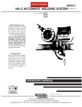
NA-5
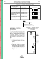
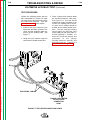
AUTOMATIC WELDING SYSTEMS
For use with the following models: NA-5N
NA-5NF
NA-5S
NA-5SF
Return to Master TOC
View Safety Info
Return to Master TOC
View Safety Info
Safety Depends on You
Lincoln arc welding and cutting
equipment is designed and built
with safety in mind. However,
your overall safety can be
increased by proper installation
... and thoughtful operation on
your part. DO NOT INSTALL,
OPERATE OR REPAIR THIS
EQUIPMENT WITHOUT READING THIS MANUAL AND THE
SAFETY PRECAUTIONS CONTAINED THROUGHOUT. And,
most importantly, think before
you act and be careful.
View Safety Info
Return to Master TOC
SERVICE MANUAL
World's Leader in Welding and Cutting Products
Premier Manufacturer of Industrial Motors
Sales and Service through Subsidiaries and Distributors Worldwide
22801 St. Clair Ave. Cleveland, Ohio 44117-1199 U.S.A. Tel. (216) 481-8100
Return to Master TOC
i
i
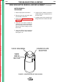
SAFETY
WARNING
CALIFORNIA PROPOSITION 65 WARNINGS
Diesel engine exhaust and some of its constituents
are known to the State of California to cause cancer, birth defects, and other reproductive harm.
The Above For Diesel Engines
The engine exhaust from this product contains
chemicals known to the State of California to cause
cancer, birth defects, or other reproductive harm.
The Above For Gasoline Engines
ARC WELDING CAN BE HAZARDOUS. PROTECT YOURSELF AND OTHERS FROM POSSIBLE SERIOUS INJURY OR DEATH.
KEEP CHILDREN AWAY. PACEMAKER WEARERS SHOULD CONSULT WITH THEIR DOCTOR BEFORE OPERATING.
Return to Master TOC
Return to Master TOC
Read and understand the following safety highlights. For additional safety information, it is strongly recommended that you purchase a copy of “Safety in Welding & Cutting - ANSI Standard Z49.1” from the American Welding Society, P.O. Box 351040,
Miami, Florida 33135 or CSA Standard W117.2-1974. A Free copy of “Arc Welding Safety” booklet E205 is available from the
Lincoln Electric Company, 22801 St. Clair Avenue, Cleveland, Ohio 44117-1199.
BE SURE THAT ALL INSTALLATION, OPERATION, MAINTENANCE AND REPAIR PROCEDURES ARE
PERFORMED ONLY BY QUALIFIED INDIVIDUALS.
FOR ENGINE
powered equipment.
1.a. Turn the engine off before troubleshooting and maintenance
work unless the maintenance work requires it to be running.
____________________________________________________
1.b. Operate engines in open, well-ventilated
areas or vent the engine exhaust fumes
outdoors.
____________________________________________________
1.c. Do not add the fuel near an open flame welding arc or when the engine is running. Stop
the engine and allow it to cool before refueling to prevent spilled fuel from vaporizing on
contact with hot engine parts and igniting. Do
not spill fuel when filling tank. If fuel is spilled,
wipe it up and do not start engine until fumes
have been eliminated.
____________________________________________________
1.d. Keep all equipment safety guards, covers and
devices in position and in good repair.Keep
hands, hair, clothing and tools away from Vbelts, gears, fans and all other moving parts
when starting, operating or repairing equipment.
____________________________________________________
Return to Master TOC
1.h. To avoid scalding, do not remove the
radiator pressure cap when the engine is
hot.
1.e. In some cases it may be necessary to remove safety
guards to perform required maintenance. Remove
guards only when necessary and replace them when the
maintenance requiring their removal is complete.
Always use the greatest care when working near moving
parts.
___________________________________________________
1.f. Do not put your hands near the engine fan. Do not attempt to
override the governor or idler by pushing on the throttle control rods while the engine is running.
___________________________________________________
1.g. To prevent accidentally starting gasoline engines while
turning the engine or welding generator during maintenance
work, disconnect the spark plug wires, distributor cap or
magneto wire as appropriate.
ELECTRIC AND
MAGNETIC FIELDS
may be dangerous
2.a. Electric current flowing through any conductor causes
localized Electric and Magnetic Fields (EMF). Welding
current creates EMF fields around welding cables and
welding machines
2.b. EMF fields may interfere with some pacemakers, and
welders having a pacemaker should consult their physician
before welding.
2.c. Exposure to EMF fields in welding may have other health
effects which are now not known.
2.d. All welders should use the following procedures in order to
minimize exposure to EMF fields from the welding circuit:
2.d.1. Route the electrode and work cables together - Secure
them with tape when possible.
2.d.2. Never coil the electrode lead around your body.
2.d.3. Do not place your body between the electrode and
work cables. If the electrode cable is on your right
side, the work cable should also be on your right side.
2.d.4. Connect the work cable to the workpiece as close as
possible to the area being welded.
2.d.5. Do not work next to welding power source.
Mar ‘95
Return to Master TOC
Return to Master TOC
ii
ELECTRIC SHOCK can kill.
ARC RAYS can burn.
3.a. The electrode and work (or ground) circuits
are electrically “hot” when the welder is on.
Do not touch these “hot” parts with your bare
skin or wet clothing. Wear dry, hole-free
gloves to insulate hands.
4.a. Use a shield with the proper filter and cover
plates to protect your eyes from sparks and
the rays of the arc when welding or observing
open arc welding. Headshield and filter lens
should conform to ANSI Z87. I standards.
3.b. Insulate yourself from work and ground using dry insulation.
Make certain the insulation is large enough to cover your full
area of physical contact with work and ground.
4.b. Use suitable clothing made from durable flame-resistant
material to protect your skin and that of your helpers from
the arc rays.
In addition to the normal safety precautions, if welding
must be performed under electrically hazardous
conditions (in damp locations or while wearing wet
clothing; on metal structures such as floors, gratings or
scaffolds; when in cramped positions such as sitting,
kneeling or lying, if there is a high risk of unavoidable or
accidental contact with the workpiece or ground) use
the following equipment:
• Semiautomatic DC Constant Voltage (Wire) Welder.
• DC Manual (Stick) Welder.
• AC Welder with Reduced Voltage Control.
4.c. Protect other nearby personnel with suitable, non-flammable
screening and/or warn them not to watch the arc nor expose
themselves to the arc rays or to hot spatter or metal.
3.c. In semiautomatic or automatic wire welding, the electrode,
electrode reel, welding head, nozzle or semiautomatic
welding gun are also electrically “hot”.
3.d. Always be sure the work cable makes a good electrical
connection with the metal being welded. The connection
should be as close as possible to the area being welded.
3.e. Ground the work or metal to be welded to a good electrical
(earth) ground.
3.f. Maintain the electrode holder, work clamp, welding cable and
welding machine in good, safe operating condition. Replace
damaged insulation.
Return to Master TOC
ii
SAFETY
3.g. Never dip the electrode in water for cooling.
3.h. Never simultaneously touch electrically “hot” parts of
electrode holders connected to two welders because voltage
between the two can be the total of the open circuit voltage
of both welders.
3.i. When working above floor level, use a safety belt to protect
yourself from a fall should you get a shock.
3.j. Also see Items 6.c. and 8.
FUMES AND GASES
can be dangerous.
5.a. Welding may produce fumes and gases
hazardous to health. Avoid breathing these
fumes and gases.When welding, keep
your head out of the fume. Use enough
ventilation and/or exhaust at the arc to keep
fumes and gases away from the breathing zone. When
welding with electrodes which require special
ventilation such as stainless or hard facing (see
instructions on container or MSDS) or on lead or
cadmium plated steel and other metals or coatings
which produce highly toxic fumes, keep exposure as
low as possible and below Threshold Limit Values (TLV)
using local exhaust or mechanical ventilation. In
confined spaces or in some circumstances, outdoors, a
respirator may be required. Additional precautions are
also required when welding on galvanized steel.
5.b. Do not weld in locations near chlorinated hydrocarbon vapors
coming from degreasing, cleaning or spraying operations.
The heat and rays of the arc can react with solvent vapors to
form phosgene, a highly toxic gas, and other irritating
products.
5.c. Shielding gases used for arc welding can displace air and
cause injury or death. Always use enough ventilation,
especially in confined areas, to insure breathing air is safe.
5.d. Read and understand the manufacturer’s instructions for this
equipment and the consumables to be used, including the
material safety data sheet (MSDS) and follow your
employer’s safety practices. MSDS forms are available from
your welding distributor or from the manufacturer.
Return to Master TOC
5.e. Also see item 1.b.
Mar ‘95
Return to Master TOC
iii
WELDING SPARKS can
cause fire or explosion.
6.a. Remove fire hazards from the welding area.
If this is not possible, cover them to prevent
the welding sparks from starting a fire.
Remember that welding sparks and hot
materials from welding can easily go through small cracks
and openings to adjacent areas. Avoid welding near
hydraulic lines. Have a fire extinguisher readily available.
6.b. Where compressed gases are to be used at the job site,
special precautions should be used to prevent hazardous
situations. Refer to “Safety in Welding and Cutting” (ANSI
Standard Z49.1) and the operating information for the
equipment being used.
Return to Master TOC
6.c. When not welding, make certain no part of the electrode
circuit is touching the work or ground. Accidental contact can
cause overheating and create a fire hazard.
6.d. Do not heat, cut or weld tanks, drums or containers until the
proper steps have been taken to insure that such procedures
will not cause flammable or toxic vapors from substances
inside. They can cause an explosion even though they have
been “cleaned”. For information, purchase “Recommended
Safe Practices for the Preparation for Welding and Cutting of
Containers and Piping That Have Held Hazardous
Substances”, AWS F4.1 from the American Welding Society
(see address above).
6.e. Vent hollow castings or containers before heating, cutting or
welding. They may explode.
6.f. Sparks and spatter are thrown from the welding arc. Wear oil
free protective garments such as leather gloves, heavy shirt,
cuffless trousers, high shoes and a cap over your hair. Wear
ear plugs when welding out of position or in confined places.
Always wear safety glasses with side shields when in a
welding area.
Return to Master TOC
iii
SAFETY
6.g. Connect the work cable to the work as close to the welding
area as practical. Work cables connected to the building
framework or other locations away from the welding area
increase the possibility of the welding current passing
through lifting chains, crane cables or other alternate circuits.
This can create fire hazards or overheat lifting chains or
cables until they fail.
6.h. Also see item 1.c.
CYLINDER may explode
if damaged.
7.a. Use only compressed gas cylinders
containing the correct shielding gas for the
process used and properly operating
regulators designed for the gas and
pressure used. All hoses, fittings, etc. should be suitable for
the application and maintained in good condition.
7.b. Always keep cylinders in an upright position securely
chained to an undercarriage or fixed support.
7.c. Cylinders should be located:
• Away from areas where they may be struck or subjected to
physical damage.
• A safe distance from arc welding or cutting operations and
any other source of heat, sparks, or flame.
7.d. Never allow the electrode, electrode holder or any other
electrically “hot” parts to touch a cylinder.
7.e. Keep your head and face away from the cylinder valve outlet
when opening the cylinder valve.
7.f. Valve protection caps should always be in place and hand
tight except when the cylinder is in use or connected for
use.
7.g. Read and follow the instructions on compressed gas
cylinders, associated equipment, and CGA publication P-l,
“Precautions for Safe Handling of Compressed Gases in
Cylinders,” available from the Compressed Gas Association
1235 Jefferson Davis Highway, Arlington, VA 22202.
FOR ELECTRICALLY
powered equipment.
8.a. Turn off input power using the disconnect
switch at the fuse box before working on
the equipment.
8.b. Install equipment in accordance with the U.S. National
Electrical Code, all local codes and the manufacturer’s
recommendations.
8.c. Ground the equipment in accordance with the U.S. National
Electrical Code and the manufacturer’s recommendations.
Return to Master TOC
Mar ‘95
Return to Master TOC
Return to Master TOC
Return to Master TOC
Return to Master TOC
iv
iv
SAFETY
PRÉCAUTIONS DE SÛRETÉ
Pour votre propre protection lire et observer toutes les instructions
et les précautions de sûreté specifiques qui parraissent dans ce
manuel aussi bien que les précautions de sûreté générales suivantes:
Sûreté Pour Soudage A L’Arc
1. Protegez-vous contre la secousse électrique:
a. Les circuits à l’électrode et à la piéce sont sous tension
quand la machine à souder est en marche. Eviter
toujours tout contact entre les parties sous tension et
la peau nue ou les vétements mouillés. Porter des
gants secs et sans trous pour isoler les mains.
b. Faire trés attention de bien s’isoler de la masse quand
on soude dans des endroits humides, ou sur un
plancher metallique ou des grilles metalliques,
principalement dans les positions assis ou couché
pour lesquelles une grande partie du corps peut être
en contact avec la masse.
c. Maintenir le por te-électrode, la pince de masse, le
câble de soudage et la machine à souder en bon et sûr
état defonctionnement.
d. Ne jamais plonger le porte-électrode dans l’eau pour
le refroidir.
e. Ne jamais toucher simultanément les par ties sous
tension des por te-électrodes connectés à deux
machines à souder parce que la tension entre les deux
pinces peut être le total de la tension à vide des deux
machines.
f. Si on utilise la machine à souder comme une source
de courant pour soudage semi-automatique, ces
precautions pour le porte-électrode s’applicuent aussi
au pistolet de soudage.
2. Dans le cas de travail au dessus du niveau du sol, se protéger
contre les chutes dans le cas ou on recoit un choc. Ne jamais
enrouler le câble-électrode autour de n’importe quelle partie
du corps.
3. Un coup d’arc peut être plus sévère qu’un coup de soliel,
donc:
a. Utiliser un bon masque avec un verre filtrant approprié
ainsi qu’un verre blanc afin de se protéger les yeux du rayonnement de l’arc et des projections quand on soude ou
quand on regarde l’arc.
b. Porter des vêtements convenables afin de protéger la
peau de soudeur et des aides contre le rayonnement de
l‘arc.
c. Protéger l’autre personnel travaillant à proximité au
soudage à l’aide d’écrans appropriés et non-inflammables.
4. Des gouttes de laitier en fusion sont émises de l’arc de
soudage. Se protéger avec des vêtements de protection libres
de l’huile, tels que les gants en cuir, chemise épaisse, pantalons sans revers, et chaussures montantes.
5. Toujours porter des lunettes de sécurité dans la zone de
soudage. Utiliser des lunettes avec écrans lateraux dans les
zones où l’on pique le laitier.
6. Eloigner les matériaux inflammables ou les recouvrir afin
de prévenir tout risque d’incendie dû aux étincelles.
7. Quand on ne soude pas, poser la pince à une endroit isolé
de la masse. Un court-circuit accidental peut provoquer un
échauffement et un risque d’incendie.
8. S’assurer que la masse est connectée le plus prés possible
de la zone de travail qu’il est pratique de le faire. Si on
place la masse sur la charpente de la construction ou
d’autres endroits éloignés de la zone de travail, on
augmente le risque de voir passer le courant de soudage
par les chaines de levage, câbles de grue, ou autres
circuits. Cela peut provoquer des risques d’incendie ou
d’echauffement des chaines et des câbles jusqu’à ce qu’ils
se rompent.
9. Assurer une ventilation suffisante dans la zone de soudage.
Ceci est particuliérement important pour le soudage de
tôles galvanisées plombées, ou cadmiées ou tout autre
métal qui produit des fumeés toxiques.
10. Ne pas souder en présence de vapeurs de chlore provenant
d’opérations de dégraissage, nettoyage ou pistolage. La
chaleur ou les rayons de l’arc peuvent réagir avec les
vapeurs du solvant pour produire du phosgéne (gas
fortement toxique) ou autres produits irritants.
11. Pour obtenir de plus amples renseignements sur la sûreté,
voir le code “Code for safety in welding and cutting” CSA
Standard W 117.2-1974.
PRÉCAUTIONS DE SÛRETÉ POUR
LES MACHINES À SOUDER À
TRANSFORMATEUR ET À
REDRESSEUR
1. Relier à la terre le chassis du poste conformement au code de
l’électricité et aux recommendations du fabricant. Le dispositif
de montage ou la piece à souder doit être branché à une
bonne mise à la terre.
2. Autant que possible, I’installation et l’entretien du poste seront
effectués par un électricien qualifié.
3. Avant de faires des travaux à l’interieur de poste, la debrancher à l’interrupteur à la boite de fusibles.
4. Garder tous les couvercles et dispositifs de sûreté à leur
place.
Mar. ‘93
RETURN TO MAIN INDEX
v
v
MASTER TABLE OF CONTENTS FOR ALL SECTIONS
Safety
...................................................
Page
i-iv
Installation . . . . . . . . . . . . . . . . . . . . . . . . . . . . . . . . . . . . . . . . . . . . . . . . Section A
Technical Specifications . . . . . . . . . . . . . . . . . . . . . . . . . . . . . . . . . . . .
A-2
Mechanical Installation . . . . . . . . . . . . . . . . . . . . . . . . . . . . . . . . . . . .
A-4
Electrical Installation . . . . . . . . . . . . . . . . . . . . . . . . . . . . . . . . . . . . . .
A-6
Electrode Polarity . . . . . . . . . . . . . . . . . . . . . . . . . . . . . . . . . . . . . . . .
A-8
Power Source Connection Diagrams . . . . . . . . . . . . . . . . . . . . . . . . . .
A-8
Operating Instructions . . . . . . . . . . . .
Safety Precautions . . . . . . . . . . . . .
Operator’s Instructions . . . . . . . . . .
Controls and Their Functions . . . . .
Setup Instructions . . . . . . . . . . . . .
Starting and Stopping Sequences . .
Setting Travel Starting and Stopping
Voltage Control Response . . . . . . .
Automatic Shutdown . . . . . . . . . . .
Cold Start Circuitry . . . . . . . . . . . . .
Security of Weld Procedure Settings
.
.
.
.
.
.
.
.
.
.
.
.
.
.
.
.
.
.
.
.
.
.
.
.
.
.
.
.
.
.
.
.
.
.
.
.
.
.
.
.
.
.
.
.
.
.
.
.
.
.
.
.
.
.
.
.
.
.
.
.
.
.
.
.
.
.
.
.
.
.
.
.
.
.
.
.
.
.
.
.
.
.
.
.
.
.
.
.
.
.
.
.
.
.
.
.
.
.
.
.
.
.
.
.
.
.
.
.
.
.
.
.
.
.
.
.
.
.
.
.
.
.
.
.
.
.
.
.
.
.
.
.
.
.
.
.
.
.
.
.
.
.
.
.
.
.
.
.
.
.
.
.
.
.
.
.
.
.
.
.
.
.
.
.
.
.
.
.
.
.
.
.
.
.
.
.
.
.
.
.
.
.
.
.
.
.
.
.
.
.
.
.
.
.
.
.
.
.
.
.
.
.
.
.
.
.
.
.
.
.
.
.
.
.
.
.
.
.
.
.
.
.
.
.
.
.
.
.
.
.
.
.
.
.
.
.
.
.
.
.
.
.
.
.
.
.
.
.
.
.
.
.
.
.
.
.
.
.
.
.
.
.
.
.
.
.
.
.
.
.
.
.
.
.
.
.
.
.
.
.
.
.
.
.
.
.
. Section B
.
B-2
.
B-2
.
B-3
.
B-4
.
B-5
.
B-6
.
B-9
.
B-10
.
B-11
.
B-12
Accessories . . . . . . . . . . . . . . . . . . . . . . . . . . . . . . . . . . . . . . . . . . . . . . . Section C
General . . . . . . . . . . . . . . . . . . . . . . . . . . . . . . . . . . . . . . . . . . . . . . . .
C-2
Listing of Accessories . . . . . . . . . . . . . . . . . . . . . . . . . . . . . . . . . . . . .
C-3
Maintenance . . . . . .
Control Box . . . .
Welding Head . .
Optional Features
....
....
....
...
.
.
.
.
.
.
.
.
.
.
.
.
.
.
.
.
.
.
.
.
.
.
.
.
.
.
.
.
.
.
.
.
.
.
.
.
.
.
.
.
.
.
.
.
.
.
.
.
.
.
.
.
.
.
.
.
.
.
.
.
.
.
.
.
.
.
.
.
.
.
.
.
.
.
.
.
.
.
.
.
.
.
.
.
.
.
.
.
.
.
.
.
.
.
.
.
.
.
.
.
.
.
.
.
.
.
.
.
.
.
.
.
.
.
.
.
.
.
.
.
.
.
.
.
.
.
.
.
.
.
.
.
.
.
.
.
.
.
.
.
.
.
.
.
. Section D
.
D-2
.
D-3
.
D-6
Theory of Operation . . . . . . . . . . . . . . . . . . . . . . . . . . . . . . . . . . . . . . . . . Section E
General Description . . . . . . . . . . . . . . . . . . . . . . . . . . . . . . . . . . . .
E-2
Input Power Circuits . . . . . . . . . . . . . . . . . . . . . . . . . . . . . . . . . . . .
E-2
Power and Voltage Boards . . . . . . . . . . . . . . . . . . . . . . . . . . . . . . . .
E-3
Control, Logic and Procedure Boards . . . . . . . . . . . . . . . . . . . . . . . .
E-4
Optional start, Crater Fill and Weld Timer Boards . . . . . . . . . . . . . . .
E-5
SCR Operation . . . . . . . . . . . . . . . . . . . . . . . . . . . . . . . . . . . . . . . . . . .
E-6
Troubleshooting . . . . . . . . . . . . . . . . . . . . . . . . . . . . . . . . . . . . . . . . . . . . Section F
Electrical Diagrams . . . . . . . . . . . . . . . . . . . . . . . . . . . . . . . . . . . . . . . . . . . . . Section G
Parts Listing . . . . . . . . . . . . . . . . . . . . . . . . . . . . . . . . . . . . . . . . . . . . . . .
NA-5
P-135
Return to Master TOC
Return to Master TOC
Return to Master TOC
Return to Master TOC
vi
NOTES
NA-5
vi
Section A
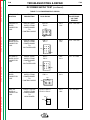
TABLE OF CONTENTS
- INSTALLATION SECTION -
Installation . . . . . . . . . . . . . . . . . . . . . . . . . . . . . . . . . . . . . . . . . .
Technical Specifications . . . . . . . . . . . . . . . . . . . . . . . . . . . . . .
Mechanical Installation . . . . . . . . . . . . . . . . . . . . . . . . . . . . . . .
Introduction . . . . . . . . . . . . . . . . . . . . . . . . . . . . . . . . . . . .
Control Box Installation . . . . . . . . . . . . . . . . . . . . . . . . . . . .
Welding Head Installation . . . . . . . . . . . . . . . . . . . . . . . . . .
Electrical Installation . . . . . . . . . . . . . . . . . . . . . . . . . . . . . . . . .
Input Power Requirements . . . . . . . . . . . . . . . . . . . . . . . . .
Control Box to Welding Head Connections . . . . . . . . . . . . . .
Power Supply to Control Box Connections . . . . . . . . . . . . . .
Electrode Polarity . . . . . . . . . . . . . . . . . . . . . . . . . . . . . . . . . . .
Power Source Connection Diagrams . . . . . . . . . . . . . . . . . . . . .
Figure A.8 — Connection of NA-5 (All) to a DC-600 . . . . . . .
Figure A.9 — Connection of NA-5 (All) to a DC-650 Pro . . . .
Figure A.10 — Connection of NA-5 (All) to a R3S-400, -600
or -800 with no Line Voltage Compensator (Obsolete) . . .
Figure A.11 — Connection of NA-5 (All) to a SAM-400 Motor
Generator or Engine Welder . . . . . . . . . . . . . . . . . . . . . . .
Figure A.12 — Connection of NA-5 (All) to a SAM-650
Engine Welder . . . . . . . . . . . . . . . . . . . . . . . . . . . . . . . . .
Figure A.13 — Connection of NA-5 to DC-1000 or DC-1500 .
Figure A.14 — Connection of NA-5 to DC-400 or CV-400 . . .
Return to Master TOC
Return to Master TOC
Return to Master TOC
Return to Master TOC
Section A
NA-5
.
.
.
.
.
.
.
.
.
.
.
.
.
.
.
.
.
.
.
.
.
.
.
.
.
.
.
.
. Section A
.
A-2
.
A-4
.
A-4
.
A-4
.
A-5
.
A-6
.
A-6
.
A-6
.
A-7
.
A-8
.
A-8
.
A-9
.
A-10
...
A-11
...
A-12
...
...
...
A-13
A-14
A-15
A-2
INSTALLATION
Return to Master TOC
Return to Section TOC
A-2
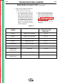
TECHNICAL SPECIFICATIONS – NA-5
MINIMUM ELECTRICAL INPUT REQUIREMENTS
115 VAC @ 3 amps 50/60 Hz power
REQUIRED WELDING POWER SOURCE
NA-5
DC Constant Voltage
WIRE FEED SPEED and GEAR RATIOS
Return to Master TOC
Return to Master TOC
Return to Master TOC
Return to Section TOC
Return to Section TOC
Return to Section TOC
GEAR RATIO
FEED SPEED RANGE
in./min (m/min)
MAX. WIRE SIZE in. (mm)
CORED WIRE
SOLID WIRE
21:1
100 - 2070 (2.54 - 52.6)
0.052 (1.3)
0.052 (1.3)
57:1
38 - 7.78 (0.96 - 19.8)
3/32 (2.4)
1/16 (1.6)
95:1
22 - 456 (0.56 - 11.6)
5/32 (4.0)
1/8 (3.2)
142:1
15 - 300 (0.38 - 7.62)
5/32 (4.0)
7/32 (5.6)
HEIGHT
in. (mm)
WEIGHT
lbs (kg)
15.05 (382)
30 (13)
PHYSICAL DIMENSIONS
MODEL
LENGTH
in. (mm)
WIDTH
in. (mm)
NA-5 Control Box
9.02 (229)
NA-5
17.87 (454)
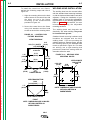
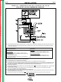
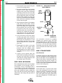
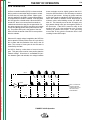
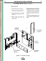
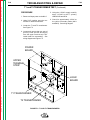
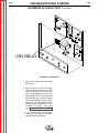
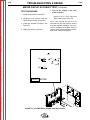
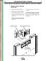
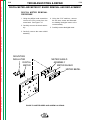
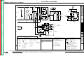
FIGURE A.1 – BASIC CONTROL AND WIRE DRIVE SYSTEM.
CONTROL BOX
HEAD MOUNTING PARTS
(WITH INSULATION
AND HARDWARE)
CONTROL
CABLE
TO
POWER
SOURCE
WIRE
STRAIGHTENER
Return to Section TOC
Return to Master TOC
Return to Master TOC
TACHOMETER
CABLE
4 FT (1.2 M) CABLE
(DRIVE MOTOR TO
CONTROL BOX)
Return to Section TOC
A-3
INSTALLATION
Return to Master TOC
Return to Master TOC
Return to Section TOC
Return to Section TOC
A-3
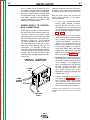
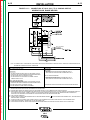
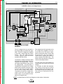
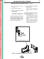
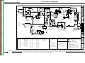
MOTOR
4 FT (1.2 M) ELECTRODE CABLES
[(TWO 4/0) CONTACT ASSEMBLY
TO CONTROL BOX]
CROSS
SEAM
ADJUSTER
GEAR BOX
CONTACT
ASSEMBLY
(OPTIONAL)
NA-5
Return to Master TOC
Return to Section TOC
A-4
MECHANICAL
INSTALLATION
1. Align the mounting holes in adapter
plate M-13945 to the holes in the
travel carriage.
2. Install four hex head screws through
the adapter plate and into the travel
carriage.
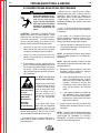
WARNING
ELECTRIC SHOCK
can kill.
Return to Master TOC
• Turn off input power to
the welding power source
using the disconnect
switch before working on
this equipment.
Return to Section TOC
A-4
INSTALLATION
INTRODUCTION
This section covers the basic requirements to
install the control box and welding head
shown in Figure A.1. This section will give
you mounting hole alignments, component
mounting clearances, and any special
instructions or precautions that must be followed when installing the control box and
mounting head.
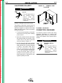
3. Secure the control box to the adapter
plate with four lock washers and four
bolts, two from the bottom and two
from the back.
Before mounting the control box onto a
fixture, you must provide mounting holes in
the fixture per the measurements provided
in Figure A.3 or dimension print S16717.
When placing the mounting holes, ensure
the controls and meters are convenient to
the operator.
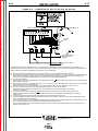
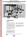
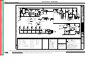
FIGURE A.2 – CONTROL BOX
CARRIAGE MOUNTING.
Return to Section TOC
Return to Master TOC
Return to Section TOC
Return to Master TOC
CONTROL BOX INSTALLATION
The control box can be mounted either on
the standard travel carriage or on a separate
fixture. It is electrically grounded by a lead
in the input cable assembly.
To install the control box on the standard
travel carriage, use mounting kit T14469 and
perform the following steps. Also refer to
Figure A.2.
NA-5
ADAPTER
PLATE
TRAVEL
CARRIAGE
CONTROL
BOX
Return to Master TOC
Return to Section TOC
A-5
To install the control box on a fixture,
perform the following steps and refer to
Figure A.3.
1. Align the mounting holes on the back
and/or bottom of the control box with
the holes you put in the fixture
according to the measurements
provided in Figure A.3.
Return to Master TOC
2. Secure the control box to the fixture
using lock washers and hex head
screws at each of the mounting holes.
Return to Section TOC
A-5
INSTALLATION
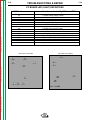
FIGURE A.3 – CONTROL BOX
FIXTURE MOUNTING.
VIEW FROM BACK
0.28 (7.11) SLOTS
4 PLACES
0.41
(10.41)
0.562 DIA (14.27)
2 HOLES
12.75
(323.85)
1.34
(34.04)
1.71
(43.43)
13.77
(349.76)
WELDING HEAD INSTALLATION
The welding head can be mounted either
with the standard head mounting hardware
or with the horizontal head and/or vertical lift
adjusters. Design the installation of your
welding head so it meets the adjustability
requirements of your welding application.
Refer to Section C, Accessories, for more
information regarding the adjustable
mounting hardware.
The welding head and electrode are
electrically “hot” when welding. They must
be insulated from ground.
Standard head mounting hardware and
insulation are shipped with the NA-5
welding head. If you are mounting the
welding head on a separate fixture, provide
the mounting holes for the standard head
mount as specified in Figure A.4. For best
arc striking, use a rigid mounting that
prevents the head from moving when the
electrode strikes the work.
FIGURE A.4 – WELDING HEAD
MOUNTING HOLES.
12.00
(304.8)
Return to Master TOC
Return to Section TOC
0.531 DIA.
(13.49)
1.09
(27.68)
1/4-20
THREAD HOLES
0.43
(10.92)
4.265
(108.33)
12.00
(304.8)
3.50
(88.9)
Return to Master TOC
2.62
(66.55)
VIEW FROM BOTTOM
1.71
(43.43)
Return to Section TOC
2.88
(73.15)
APPROXIMATE
INSULATOR
SIZE
1/4-20 THREAD HOLES
FRONT
NOTE: DIMENSIONS ARE IN INCHES
WITH MILLIMETERS IN
PARENTHESES.
NA-5
4.5
(114.30)
NOTE: DIMENSIONS ARE IN INCHES
WITH MILLIMETERS IN
PARENTHESES.
Return to Master TOC
Return to Section TOC
A-6
When mounting the welding head to the
standard travel carriage, (see 305-B sec.
T2.2.4) mount it so only a minimum of
overhang weight exists. Mount the head so
it stays within the dimension shown in Figure
A.5.
FIGURE A.5 – MOUNT TO CARRIAGE
OVERHANG DIMENSION.
350 volt-amperes of 115 VAC 50/60 Hz
power is required for the wire feed motor and
controls. Another 250 volt-amperes may be
required depending on the travel circuit.
If the 4 ft (1.2 m) cables are not sufficient,
install a K335 or K338 control to head
extension cable of the length ordered [up to
30 ft (9.1 m)]. The K335, for the NA-5S
head, includes motor, tachometer and flux
hopper lead extensions with polarized plugs
on each end, and electrode cables. The
K338 for the NA-5N, NF, and SF heads is
the same as the K335 without the flux
hopper lead extension.
ELECTRICAL
INSTALLATION
WARNING
ELECTRIC SHOCK
can kill.
• Do not touch electrically
live parts such as output
terminals or internal
wiring.
Return to Master TOC
INPUT POWER REQUIREMENTS
All welding heads include a 4 ft (1.2 m)
motor cable and motor tachometer cable.
Insert the plugs on these cables into the
matching receptacles on the side of the
control box.
Return to Master TOC
Return to Master TOC
Return to Section TOC
Return to Section TOC
nection diagrams for connecting automatic
welding systems to various welding power
sources.
CONTROL BOX TO WELDING
HEAD CONNECTIONS
19 IN.
(483 MM)
Return to Section TOC
A-6
INSTALLATION
This section provides information on proper
wiring procedures for the NA-5 welding system. This section also provides basic con-
NA-5
The NA-5N and NA-5S also include two 4 ft
(1.2 m) lengths of electrode cable. Bolt the
terminals at one end of the the cable pair to
the wire contact assembly and the terminals
at the other end to the electrode leads on the
power source to control cable assembly.
Properly insulate the bolted connection.
When the K335 or K338 extension cables are
used between the controls and heads, the 4 ft
(1.2 m) lengths of electrode cable are not
used. If currents or duty cycles higher than
1000 amps at 80% duty cycle will be used,
add additional electrode cable per Table A.1.
TABLE A.1
80% Duty Cycle
Below 1000 amps
Two 4/0
1000 to 1300 amps Three 4/0
1300 to 1500 amps Four 4/0
Return to Master TOC
Return to Section TOC
A-7
INSTALLATION
The “F” models do not include the 4 ft (1.2
m) lengths of electrode cable as standard.
If you are not using a K335 or K338 extension cable for the NA-5NF or NA-5SF, order
an appropriate length of the needed electrode cable. Connect it between the wire
contact assembly and the control cable
assembly as described above.
Return to Master TOC
Return to Section TOC
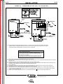
POWER SUPPLY TO CONTROL
BOX CONNECTIONS
At the NA-5 control box, in order to activate
the NA-5 weld current sensing switch, the
electrode cables of the control cable
assembly must be placed under the clamp
bar on the left-hand side of the control box,
as shown in Figure A.6. This is required
for proper operation of the reed switch.
The nuts holding the clamp bar in place
need only to be pulled up snug. Do not
overtighten. If a carriage is used, the
electrode cables should also be clamped
to it with the cable clamp supplied on the
carriage. Do not clamp the control cable
under the travel carriage clamp but route it
over its top.
Return to Master TOC
CLAMP
BAR
Insert the polarized connector of the K215
or K597* control cable into the matching
receptacle on the side of the control box.
With the power source off, connect the
control cable assembly to the power
source as follows:
1. If using the multi-process power
source (SAM, SA-800, SAF-600,
DC-400, DC-600, DC-1000, or DC1500 types), be sure it is properly set
for the welding process being used
per the connection diagram (Figures
A.8 to A.14).
2. Connect the K215 control cable
leads to the power source terminal
strip exactly as specified on the
connection diagram.* Include all
jumpers on the terminal strips as
shown on the diagram. Do not put
on any other jumpers. If currents or
duty cycles higher than 1000 amps
at 80% duty cycle will be used, add
additional electrode cables to the
K215 assembly per Table A.1.
3 Depending on the power source and
the process to be used, the jumpers
on the NA-5 voltage board may have
to be changed. As shipped, the
NA-5 is connected for use with the
DC-400, DC-600, DC-1000, and
DC-1500 type power sources. For
other power sources, refer to the
appropriate connection diagram and
to IM305 Sec. T3.6.
4. Connect work leads of sufficient size
and length per Table A.1. between
the “To Work” stud on the power
source and the work. Be sure the
connection to the work makes a tight
and clean metal-to-metal contact.
FROM
POWER
SOURCE
*The K597 cable assembly has a 14-pin MS-type
connector for use with later model Lincoln CV power
sources.
TO
WELDING
HEAD
Return to Master TOC
Return to Section TOC
Return to Section TOC
FIGURE A.6 – CONTROL BOX
ELECTRICAL CONNECTIONS.
A-7
NA-5
Return to Master TOC
Return to Section TOC
A-8
ELECTRODE POLARITY
ELECTRIC SHOCK
can kill.
• Turn off input power to
the welding power
source
using
the
disconnect
switch
before working on this
equipment.
Return to Master TOC
Return to Section TOC
The polarity of the NA-5 control circuit is
shipped connected for electrode positive. If
electrode negative is required, two leads
inside the NA-5 control must be reversed.
Proceed as follows:
1. Turn off the input power to the NA-5
control box by turning off the welding
power source.
Return to Master TOC
Return to Master TOC
2. Open the control box door and locate
the terminal strips on the back of the
control box in the lower left-hand
corner as shown in Figure A.7.
Return to Section TOC
FIGURE A.7 – TERMINAL STRIP
LOCATION.
WARNING
Polarity is changed at the power source.
Return to Section TOC
A-8
INSTALLATION
3. On the right end of the lower terminal
strip, interchange the black and white
leads going to the terminals marked
(+) and (-). The black lead (#67)
must be connected to the same
polarity as the electrode welding lead;
i.e. if the electrode is positive,
connect the black lead to the (+)
terminal on the terminal strip. The
white lead (#21) is connected to the
opposite polarity terminal.
NA-5
TERMINAL
STRIPS
POWER SOURCE
CONNECTION DIAGRAMS
The following section contains the wiring
diagrams necessary to connect the
applicable power source to the control box.
If there is no diagram, refer to power source
manual.
WARNING
ELECTRIC SHOCK
can kill.
• Turn off input power to
the welding power
source
using
the
disconnect
switch
before working on this
equipment.
INSTALLATION
Return to Master TOC
Return to Section TOC
A-9
A-9
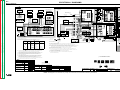
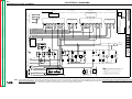
FIGURE A.8 – CONNECTION OF NA-5 (ALL) TO A DC-600.
P
TO NA-5 INPUT
CABLE PLUG
B
.A.
NOTE:
Return to Master TOC
Return to Master TOC
Return to Master TOC
Return to Section TOC
Return to Section TOC
Return to Section TOC
A
P
DIAGRAM SHOWS ELECTRODE CONNECTED POSITIVE.
TO CHANGE POLARITY, TURN POWER OFF, REVERSE THE
ELECTRODE AND WORK CABLES AT THE POWER SOURCE
AND POSITON THE SWITCH ON POWER SOURCE TO PROPER
POLARITY. REFER TO NA-5 OPERATING MANUAL FOR REQUIRED
NA-5 CONTROL BOX POLARITY CONNECTIONS.
CONNECT TO CABLES FROM NA-5
WIRE CONTACT ASSEMBLY
B
CONNECT
TO WORK
ALL CODES:
TURN OFF INPUT POWER
ADJUST THE POWER SOURCE: DC-600:
1. CONNECT ELECTRODE CABLES TO TERMINAL OF DESIRED POLARITY.
2. SET TOGGLE SWITCH TO SAME POLARITY AS THE ELECTRODE CABLE
CONNECTION.
3. SET TOGGLE SWITCH TO "REMOTE".
4. SET MODE SWITCH TO THE DESIRED POSITION FOR THE PROCESS TO BE USED.
DC-600 CODES 8046-8200:
FOR SUB ARC:
1. SET MODE SWITCH TO CV SUB ARC.
2. WHITE LEAD ON CONTROL PC BOARD IS CONNECTED TO PIN "M".
DC-600 CODES 8000-8045:
FOR SUB ARC:
1. SET MODE SWITCH TO CV SUB ARC.
2. WHITE LEAD ON CONTROL PC BOARD IS CONNECTED TO PIN "M" AND BLUE
LEAD IS CONNECTED TO "W".
FOR NR-203 ELECTRODES:
1. SET MODE SWITCH TO CV INNERSHIELD.
2. WHITE LEAD ON CONTROL PC BOARD IS CONNECTED TO PIN "I".
FOR ALL OPEN ARC PROCESSES EXCEPT NR-302 AND NR-203 ELECTRODES:
1. SET MODE SWITCH TO CV INNERSHIELD.
2. WHITE LEAD ON CONTROL PC BOARD IS CONNECTED TO PIN "M" AND BLUE
LEAD IS CONNECTED TO "W".
FOR ALL OPEN ARC PROCESSES EXCEPT MR-203 ELECTRODES:
1. SET MODE SWITCH TO CV INNERSHIELD.
2. WHITE LEAD ON CONTROL PC BOARD IS CONNECTED TO PIN "M".
DC-600 CODES ABOVE 8200:
FOR SUB ARC:
1. SET MODE SWITCH TO CV SUB ARC.
FOR ALL OPEN ARC PROCESSES:
2. SET MODE SWITCH TO CV INNERSHIELD.
FOR OPTIMUM PERFORMANCE WITH NA-5, DC-600'S WITH CODES 8288 AND
ABOVE ARE PREFERRED. FOR ADDITIONAL INSTALLATION INSTRUCTIONS,
SEE NA-5 OPERATING MANUAL.
FOR NR-203 AND NR-302 ELECTRODES:
1. SET MODE SWITCH TO CV INNERSHIELD.
2. WHITE LEAD ON CONTROL PC BOARD IS CONNECTED TO PIN "I"
AND BLUE LEAD IS CONNECTED TO "S".
N.A. ON EARLIER DC-600'S, #67 TERMINAL WAS ALSO ON THE TERMINAL STRIP.
N.B. WELDING CABLES MUST BE OF PROPER CAPACITY FOR THE CURRENT AND DUTY CYCLE OF IMMEDIATE AND FUTURE APPLICATIONS.
N.C. EXTEND LEAD #21 USING #14 OR LARGER INSULATED WIRE PHYSICALLY SUITABLE FOR THE INSTALLATION. AN S-16586 - [ ] REMOTE VOLTAGE SENSING WORK
LEAD IS AVAILABLE FOR THIS PURPOSE. CONNECT IT DIRECTLY TO THE WORK PIECE KEEPING IT SEPARATE FROM THE WELDING WORK CABLE CONNECTION
TO THE WORK PIECE. FOR CONVENIENCE, THIS EXTENDED #21 LEAD SHOULD BE TAPED ALONG THE WELDING WORK CABLE.
N.D. TAPE UP BOLTED CONNECTION.
N.E. CONNECT THE NA-5 CONTROL CABLE GROUNDING LEAD TO THE FRAME TERMINAL MARKED
NEAR THE POWER SOURCE TERMINAL STRIP. THE POWER
SOURCE MUST BE PROPERLY GROUNDED.
N.F. IF USING AN OLDER K-215 CONTROL CABLE: CONNECT LEAD #75 TO #75 ON TERMINAL STRIP, CONNECT LEAD #76 TO #76 ON TERMINAL STRIP, CONNECT
LEAD #77 TO #77 ON TERMINAL STRIP.
N.G. THE JUMPERS ON THE NA-5 VOLTAGE BOARD MUST BE CONNECTED AS FOLLOWS: CONNECT RED JUMPER TO PIN "S". CONNECT WHITE JUMPER TO PIN "B".
N.H. CONNECT A JUMPER FROM "N" TO "P". THERE IS NO NPS TERMINAL STRIP ON DC-600 CODES ABOVE 8200.
N.J. FOR PROPER NA-5 OPERATION, THE ELECTRODE CABLES MUST BE SNUGGED UNDER THE CLAMP BAR ON THE LEFT SIDE OF THE NA-5 CONTROL BOX.
CLEVELAND, OHIO U.S.A.
NA-5
A-10
INSTALLATION
Return to Master TOC
Return to Section TOC
A-10
FIGURE A.9 – CONNECTION OF NA-5 (ALL) TO A DC-650 PRO
P
P
CONTROL
CABLE
P
6
TO NA-5 INPUT
CABLE PLUG
Return to Master TOC
Return to Section TOC
TO NA-5 INPUT
CABLE PLUG
A
CONNECT TO CABLES FROM
NA-5 WIRE CONTACT ASSEMBLY
A
CONNECT TO CABLES FROM NA-5
WIRE CONTACT ASSEMBLY
R
Return to Master TOC
Return to Master TOC
Return to Section TOC
Return to Section TOC
CONNECT
TO WORK
NOTE: ABOVE DIAGRAMS SHOW ELECTRODE CONNECTED POSITIVE. TO CHANGE POLARITY, TURN POWER OFF, REVERSE THE ELECTRODE
AND WORK CABLES AT THE POWER SOURCE AND POSITION THE SWITCH ON THE POWER SOURCE TO PROPER POLARITY. REFER TO
NA-5 OPERATING MANUAL FOR REQUIRED NA-5 CONTROL BOX POLARITY CONNECTIONS.
DC650 PRO POWER SOURCE SETTINGS
1. TURN OFF INPUT POWER.
2. CONNECT ELECTRODE CABLES TO TERMINALS OF DESIRED POLARITY.
3. SET TOGGLE SWITCH TO SAME POLARITY AS ELECTRODE CABLE CONNECTION.
4. SET TOGGLE SWITCH TO REMOTE.
5. SET MODE SWITCH TO DESIRED POSITION FOR THE PROCESS TO BE USED.
6. CONNECT NEGATIVE OUTPUT CABLES TO MATCH MODE SWITCH SETTING.
N.A. WELDING CABLES MUST BE SIZED FOR CURRENT AND DUTY CYCLE OF APPLICATION.
N.B. EXTEND LEAD #21A BY REMOVING LEAD #21A FROM THE TERMINAL STRIP AND CONNECTING IT TO A #14 OR LARGER INSULATED WIRE PHYSICALLY SUITABLE FOR
THE INSTALLATION.
N.C. EXTEND LEAD #21 USING A #14 OR LARGER INSULATED WIRE PHYSICALLY SUITABLE FOR INSTALLATION.
N.D. CONNECT EXTENDED LEAD DIRECTLY TO THE WORK PIECE KEEPING IT SEPARATE FROM THE WELDING WORK CABLE CONNECTION TO THE WORK PIECE. FOR
CONVENIENCE, THIS EXTENDED LEAD SHOULD BE TAPED ALONG THE WELDING WORK CABLE.
N.E. TAPE UP CONNECTION.
N.F. FOR PROPER NA-5 OPERATION, THE ELECTRODE CABLES MUST BE SNUGGED UNDER THE CLAMP BAR ON THE LEFT SIDE OF THE NA-5 CONTROL BOX.
N.G. CONNECT NEGATIVE OUTPUT CABLES TO STUDS TO MATCH DC650 PRO MODE SWITCH SETTING.
N.H. THE JUMPERS ON THE NA-5 VOLTAGE BOARD MUST BE CONNECTED AS FOLLOWS: CONNECT RED JUMPER TO PIN "S", CONNECT WHITE JUMPER TO PIN "B".
N.J. IF USING AN OLDER K-215 CONTROL CABLE, CONNECT LEAD #75 TO #75 ON TERMINAL STRIP, CONNECT LEAD #76 TO #76 ON THE TERMINAL STRIP, CONNECT
LEAD #77 TO #77 ON THE TERMINAL STRIP.
N.K. CONNECT THE NA-5 CONTROL CABLE GROUNDING LEAD TO THE FRAME TERMINAL MARKED
NEAR THE POWER SOURCE TERMINAL STRIP.
CLEVELAND, OHIO U.S.A.
NA-5
Return to Master TOC
Return to Section TOC
A-11
A-11
INSTALLATION
FIGURE A.10 – CONNECTION OF NA-5 (ALL) TO A R3S-400, -600, OR -800
WITH NO LINE VOLTAGE COMPENSATOR (OBSOLETE).
Return to Master TOC
Return to Master TOC
Return to Section TOC
Return to Section TOC
B
B
B
POSITIVE
NOTE: ABOVE DIAGRAM SHOWS ELECTRODE CONNECTED POSITIVE. TO CHANGE POLARITY, TURN POWER OFF, REVERSE THE ELECTRODE AND WORK CABLES AT THE
POWER SOURCE AND POSITION THE SWITCH ON POWER SOURCE TO PROPER POLARITY. REFER TO NA-5 OPERATING MANUAL FOR REQUIRED NA-5 CONTROL
BOX POLARITY CONNECTIONS.
R3S POWER SOURCE SETTINGS
TURN POWER SOURCE OFF.
FOR ALL PROCESSES:
1. CONNECT ELECTRODE CABLE TO TERMINAL OF DESIRED POLARITY.
2. SET THE POLARITY SWITCH TO THE SAME POLARITY AS THE ELECTRODE
CABLE CONNECTION.
3. SET TOGGLE SWITCH TO REMOTE.
4. INSTALL VOLTAGE TRIANGLE IN A POSITION AS CLOSE AS POSSIBLE TO
THE DESIRED ARC VOLTAGE.
NA-5 SETTINGS
FOR SUB ARC:
1. RED LEAD ON VOLTAGE PC BOARD IS CONNECTED TO PIN "S".
2. WHITE LEAD ON VOLTAGE PC BOARD IS CONNECTED TO PIN "A".
FOR ALL OPEN ARC PROCESSES:
1. RED LEAD ON VOLTAGE PC BOARD IS CONNECTED TO PIN "F".
2. WHITE LEAD ON VOLTAGE PC BOARD IS CONNECTED TO PIN "A".
Return to Master TOC
Return to Section TOC
FOR ADDITIONAL INSTALLATION INSTRUCTIONS, SEE NA-5 OPERATING MANUAL.
N.A. ADD JUMPER FROM #75 TO #76, USING INSULATED COPPER WIRE.
N.B. WELDING CABLES MUST BE OF PROPER CAPACITY FOR THE CURRENT AND DUTY CYCLE OF IMMEDIATE AND FUTURE APPLICATIONS.
N.C. EXTEND LEAD #21 USING #14 OR LARGER INSULATED WIRE PHYSICALLY SUITABLE FOR THE INSTALLATION. AN S -16586 [ ] REMOTE VOLTAGE-SENSING WORK LEAD
IS AVAILABLE FOR THIS PURPOSE. CONNECT IT DIRECTLY TO THE WORK PIECE, KEEPING IT SEPARATE FROM THE WELDING WORK CABLE CONNECTION TO THE
WORK PIECE. FOR CONVENIENCE, THIS EXTENDED #21 LEAD SHOULD BE TAPED ALONG THE WELDING WORK CABLE.
N.D. TAPE UP BOLTED CONNECTION.
N.E. CONNECT THE NA-5 CONTROL CABLE GROUNDING LEAD TO THE FRAME TERMINAL MARKED
, NEAR THE POWER SOURCE TERMINAL STRIP. THE POWER SOURCE
MUST BE PROPERLY GROUNDED.
N.F. IF USING AN OLDER K-215 CONTROL CABLE: CONNECT LEAD #75 TO #75 ON TERMINAL STRIP, CONNECT LEAD #76 TO #77 ON TERMINAL STRIP, CONNECT
LEAD #77 TO #76 ON TERMINAL STRIP, AND ADD JUMPER PER N.A.
N.G. ON EARLIER R3S MACHINES, #67 AND #1 TERMINALS WERE ALSO ON THE TERMINAL STRIP.
N.H. THE UPPER TERMINAL STRIP (#75, #76, #77) WAS NOT PRESENT ON EARLY R3S MACHINES. THOSE MACHINES ARE NOT COMPATIBLE WITH THE NA-5 SINCE THERE
CAN BE NO ADJUSTMENT OF VOLTAGE BY THE NA-5.
N.J. FOR PROPER NA-5 OPERATION, THE ELECTRODE CABLES MUST BE SNUGGED UNDER THE CLAMP BAR ON THE LEFT SIDE OF THE NA-5 CONTROL BOX.
CLEVELAND, OHIO U.S.A.
NA-5
Return to Section TOC
Return to Master TOC
Return to Section TOC
Return to Master TOC
A-12
A-12
INSTALLATION
FIGURE A.11 – CONNECTION OF NA-5 (ALL) TO A SAM-400 MOTOR
GENERATOR OR ENGINE WELDER.
BOLT TO CABLES
FROM NA-5
WIRE CONTACT
ASSEMBLY
P
N.B.
N.B.
Return to Master TOC
Return to Master TOC
Return to Section TOC
Return to Section TOC
NOTE: TO CHANGE POLARITY, TURN POWER OFF, AND POSITION THE SWITCH ON POWER SOURCE TO PROPER POLARITY. REFER TO NA-5 OPERATING MANUAL FOR
REQUIRED NA-5 CONTROL BOX POLARITY CONNECTIONS.
SAM POWER SOURCE SETTINGS
NA-5 SETTINGS
TURN POWER SOURCE OFF.
FOR SUB ARC:
1. RED LEAD ON VOLTAGE PC BOARD IS CONNECTED TO PIN "S".
2. WHITE LEAD ON VOLTAGE PC BOARD IS CONNECTED TO PIN "A".
FOR SUB ARC:
1. SET THE ELECTRODE POLARITY SWITCH TO THE VARIABLE VOLTAGE
POSITION OF THE POLARITY DESIRED FOR THE PROCESS BEING USED.
2. SET THE TOGGLE SWITCH TO CONSTANT VOLTAGE.
3. SET THE CONSTANT VOLTAGE CONTROL TO NUMBER 7 AND THE
CURRENT CONTROL TO 500.
FOR ALL OPEN ARC PROCESSES:
1. SET THE ELECTRODE POLARITY SWITCH TO THE CONSTANT VOLTAGE
POSITION OF THE POLARITY DESIRED FOR THE PROCESS BEING USED.
2. SET THE TOGGLE SWITCH TO CONSTANT VOLTAGE.
3. SET THE CONSTANT VOLTAGE CONTROL TO NUMBER 5.
FOR ALL OPEN ARC PROCESSES:
1. RED LEAD ON VOLTAGE PC BOARD IS CONNECTED TO PIN "F".
2. WHITE LEAD ON VOLTAGE PC BOARD IS CONNECTED TO PIN "A".
FOR ADDITIONAL INSTALLATION INSTRUCTIONS, SEE NA-5 OPERATING MANUAL.
N.A. REMOVE SAM PORTABLE FIELD CONTROL AND CONNECT NA-5 CONTROL CABLE.
N.B. WELDING CABLES MUST BE OF PROPER CAPACITY FOR THE CURRENT AND DUTY CYCLE OF IMMEDIATE AND FUTURE APPLICATIONS.
N.C. EXTEND LEAD #21 USING #14 OR LARGER INSULATED WIRE PHYSICALLY SUITABLE FOR THE INSTALLATION. AN S-16586-[ ] REMOTE VOLTAGE-SENSING WORK LEAD
IS AVAILABLE FOR THIS PURPOSE. CONNECT IT DIRECTLY TO THE WORK PIECE, KEEPING IT SEPARATE FROM THE WELDING WORK CABLE CONNECTION TO
WORK PIECE. FOR CONVENIENCE, THIS EXTENDED #21 LEAD SHOULD BE TAPED ALONG THE WELDING WORK CABLE.
N.D. TAPE UP BOLTED CONNECTION.
N.E. CONNECT THE NA-5 CONTROL CABLE GROUNDING LEAD TO THE FRAME TERMINAL MARKED
, NEAR THE POWER SOURCE TERMINAL STRIP. THE POWER SOURCE
MUST BE PROPERLY GROUNDED.
N.F. IF USING AN OLDER K-215 CONTROL CABLE: CONNECT LEAD #76 TO #75 ON TERMINAL STRIP, CONNECT LEADS #75 AND #77 TO #76 ON TERMINAL STRIP.
N.G. ON EARLIER SAM MACHINES, #1 TERMINAL WAS ALSO ON THE TERMINAL STRIP.
N.H. FOR PROPER NA-5 OPERATION, THE ELECTRODE CABLES MUST BE SNUGGED UNDER THE CLAMP BAR ON THE LEFT SIDE OF THE NA-5 CONTROL BOX.
CLEVELAND, OHIO U.S.A.
NA-5
INSTALLATION
Return to Master TOC
Return to Section TOC
A-13
A-13
FIGURE A.12 – CONNECTION OF NA-5 (ALL) TO A SAM-650 ENGINE WELDER.
POWER SOURCE
Return to Master TOC
Return to Section TOC
TO NA-5 INPUT
CABLE PLUG
NOTE: TO CHANGE POLARITY, TURN POWER OFF, AND
POSITION THE SWITCH ON POWER SOURCE TO
PROPER POLARITY. REFER TO NA-5
OPERATING MANUAL FOR REQUIRED
NA-5 CONTROL BOX POLARITY CONNECTIONS.
BOLT TO CABLES
FROM NA-5
WIRE CONTACT
ASSEMBLY
"TAP"
P
P
P
Return to Master TOC
Return to Master TOC
Return to Section TOC
Return to Section TOC
..
SAM POWER SOURCE SETTINGS
NA-5 SETTINGS
TURN POWER SOURCE OFF.
FOR SUB ARC:
1. RED LEAD ON VOLTAGE PC BOARD IS CONNECTED TO PIN "S".
2. WHITE LEAD ON VOLTAGE PC BOARD IS CONNECTED TO PIN "A".
FOR SUB ARC:
1. SET THE ELECTRODE POLARITY SWITCH TO THE POLARITY DESIRED FOR THE
PROCESS BEING USED.
2. SET THE TOGGLE SWITCH TO CONSTANT VOLTAGE.
3. SET THE CONSTANT VOLTAGE CONTROL TO NUMBER 7.
4. CONNECT THE TAP CABLE TO THE "300-575, MAX, SLOPE" STUD.
FOR ALL OPEN ARC PROCESSES:
1. SET THE ELECTRODE POLARITY SWITCH TO THE POLARITY DESIRED FOR THE
PROCESS BEING USED.
2. SET THE TOGGLE SWITCH TO CONSTANT VOLTAGE.
3. SET THE CONSTANT VOLTAGE CONTROL TO NUMBER 5.
4. CONNECT THE TAP CABLE TO THE "450-MAX, MED SLOPE" STUD.
FOR ALL OPEN ARC PROCESSES:
1. RED LEAD ON VOLTAGE PC BOARD IS CONNECTED TO PIN "F".
2. WHITE LEAD ON VOLTAGE PC BOARD IS CONNECTED TO PIN "A".
FOR ADDITIONAL INSTALLATION INSTRUCTIONS, SEE NA-5 OPERATING MANUAL.
N.A. REMOVE SAM PORTABLE FIELD CONTROL AND CONNECT NA-5 CONTROL CABLE.
N.B. WELDING CABLES MUST BE OF PROPER CAPACITY FOR THE CURRENT AND DUTY CYCLE OF IMMEDIATE AND FUTURE APPLICATIONS.
N.C. EXTEND LEAD #21 USING #14 OR LARGER INSULATED WIRE PHYSICALLY SUITABLE FOR THE INSTALLATION. AN S-16586- [ ] REMOTE VOLTAGE-SENSING WORK
LEAD IS AVAILABLE FOR THIS PURPOSE. CONNECT IT DIRECTLY TO THE WORK PIECE, KEEPING IT SEPARATE FROM THE WELDING WORK CABLE CONNECTION
TO THE WORK PIECE. FOR CONVENIENCE, THIS EXTENDED #21 LEAD SHOULD BE TAPED ALONG THE WELDING WORK CABLE.
N.D. TAPE UP BOLTED CONNECTION.
N.E. CONNECT THE NA-5 CONTROL CABLE GROUNDING LEAD TO THE FRAME TERMINAL MARKED
NEAR THE POWER SOURCE TERMINAL STRIP. THE POWER
SOURCE MUST BE PROPERLY GROUNDED.
N.F. IF USING AN OLDER K-215 CONTROL CABLE: CONNECT LEAD #76 TO #75 ON TERMINAL STRIP, CONNECT LEADS #75 AND #77 TO #76 ON TERMINAL STRIP.
N.G. ON EARLIER SAM MACHINES, #1 TERMINAL WAS ALSO ON THE TERMINAL STRIP.
N.H. FOR PROPER NA-5 OPERATION, THE ELECTRODE CABLES MUST BE SNUGGED UNDER THE CLAMP BAR ON THE LEFT SIDE OF THE NA-5 CONTROL BOX.
CLEVELAND, OHIO U.S.A.
NA-5
Return to Master TOC
Return to Section TOC
A-14
A-14
INSTALLATION
FIGURE A.13 – CONNECTION OF NA-5 TO DC-1000 OR DC-1500.
INPUT CABLE PLUG
Return to Master TOC
Return to Section TOC
POWER SOURCE
CONTROL
CABLE
P
BOLT TO CABLES FROM
NA-5 WIRE CONTACT
ASSEMBLY
CONNECT TO WORK
Return to Section TOC
Return to Master TOC
Return to Section TOC
Return to Master TOC
THE DIAGRAM SHOWS ELECTRODE CONNECTED POSITIVE. TO CHANGE POLARITY, TURN POWER OFF, REVERSE THE ELECTRODE AND WORK LEADS AT THE
POWER SOURCE, POSITION THE POSITIVE-NEGATIVE SWITCH ON THE POWER SOURCE TO CORRESPOND TO THE POLARITY OF THE ELECTRODE CABLE CONNECTION.
REFER TO NA-5 OPERATING MANUAL FOR REQUIRED NA-5 CONTROL BOX POLARITY CONNECTIONS.
N.A. WELDING CABLES MUST BE OF PROPER CAPACITY FOR THE CURRENT AND DUTY CYCLE OF IMMEDIATE AND FUTURE APPLICATIONS.
N.B. EXTEND LEAD 21 USING #14 OR LARGER INSULATED WIRE PHYSICALLY SUITABLE FOR THE INSTALLATION. AN S-16586-[ ] REMOTE VOLTAGE-SENSING WORK LEAD
IS AVAILABLE FOR THIS PURPOSE. CONNECT IT DIRECTLY TO THE WORK PIECE KEEPING IT SEPARATE FROM THE WELDING WORK CABLE CONNECTION TO
WORK PIECE. FOR CONVENIENCE, THIS EXTENDED #21 LEAD SHOULD BE TAPED ALONG THE WELDING WORK CABLE.
N.C. TAPE UP BOLTED CONNECTION.
N.D. CONNECT THE NA-5 CONTROL CABLE GROUND LEAD TO THE FRAME TERMINAL MARKED
NEAR THE POWER SOURCE TERMINAL STRIP. THE POWER SOURCE
MUST BE PROPERLY GROUNDED.
N.E. IF USING AN OLDER AUTOMATIC CONTROL CABLE WITH LEADS 75, 76, 77; CONNECT LEAD 75 TO #75 ON TERMINAL STRIP, CONNECT LEAD #76 TO #74 ON TERMINAL
STRIP, CONNECT LEAD #77 TO #73 ON TERMINAL STRIP.
N.F. CONNECT THE JUMPERS ON THE NA-5 VOLTAGE BOARD AS FOLLOWS: CONNECT RED JUMPER TO PIN "S". CONNECT WHITE JUMPER TO PIN "B".
N.G. SET THE DC-1000 OR DC-1500 CONTROLS AS FOLLOWS: SET THE CONTROL SWITCH TO "OUTPUT CONTROL REMOTE".
FOR SUBMERGED ARC PROCESSES, SET THE MODE SWITCH TO "C.V. SUBMERGED ARC". FOR OPEN ARC PROCESSES, SET THE MODE
SWITCH TO "C.V. INNERSHIELD"
N.H. FOR PROPER OPERATION, THE ELECTRODE CABLE MUST BE SNUGGED UNDER THE CLAMP BAR ON THE LEFT SIDE OF THE NA-5 CONTROL BOX.
N.J. TERMINALS #73 AND #74 WERE NOT PRESENT ON DC-1500 MACHINES BELOW CODE 8294. THESE EARLIER CODE MACHINES ARE NOT SUITABLE FOR
USE WITH THE NA-5.
N.K. ALTERNATIVE 500 AMP POSITIVE TERMINAL CONNECTION PROVIDED ON DC-1000 MODELS ABOVE CODE 9500 ONLY.
N.L. ALTERNATE SUBMERGED ARC MODE AVAILABLE FOR IMPROVED ARC STABILITY IN HIGH CURRENT, LARGE PUDDLE, SLOW TRAVEL PROCEDURES BY MAKING
SPECIAL CONNECTIONS ON BOTH DC-1500 AND NA-5.
ON DC-1500 CONTROL BOARD (G-1530-2 AND SUPERSEDING) REMOVE RED AND BLUE JUMPERS FROM "FR" PINS AND RECONNECT TO CORRESPONDING "SR" PINS.
ON NA-5 VOLTAGE BOARD (G-1556-1 AND SUPERSEDING) WHITE JUMPER MUST BE CONNECTED TO PIN "D".
NA-5 PIN "D" CONNECTION MAY ALSO BE USED FOR SOME PROCEDURES ON DC-1500 WITHOUT CONTROL BOARD JUMPERS, DC-1500 WITH CONTROL BOARD
JUMPERS ON "FR" PINS OR DC-1000.
CLEVELAND, OHIO U.S.A.
NA-5
Return to Master TOC
Return to Section TOC
A-15
A-15
INSTALLATION
FIGURE A.14 – CONNECTION OF NA-5 TO DC-400 OR CV-400.
POWER SOURCE
Return to Master TOC
Return to Section TOC
TO NA-5 INPUT CABLE PLUG
C
B
A
32
31
2
4
GND
N.H.
N.E.
CONTROL
CABLE
N.D. AND N.H.
21
POSITIVE
NEGATIVE
N.D.
N.B. AND N.C.
BOLT TO CABLES FROM NA-5
WIRE CONTACT ASSEMBLY
N.A.
Return to Master TOC
Return to Section TOC
CONNECT TO WORK
THE DIAGRAM SHOWS ELECTRODE CONNECTED POSITIVE. TO CHANGE POLARITY, TURN POWER OFF, REVERSE THE ELECTRODE AND WORK LEADS AT THE
POWER SOURCE AND POSITION THE SWITCH ON POWER SOURCE (IF EQUIPPED), TO PROPER POLARITY. REFER TO NA-5 OPERATING MANUAL FOR REQUIRED
NA-5 CONTROL BOX POLARITY CONNECTIONS. ALSO REFER TO NOTE N.H.
FOR ADDITIONAL INSTALLATION INSTRUCTIONS, SEE NA-5 OPERATING MANUAL.
N.A. WELDING CABLES MUST BE OF PROPER CAPACITY FOR THE CURRENT AND DUTY CYCLE OF IMMEDIATE AND FUTURE APPLICATIONS.
N.B. EXTEND LEAD #21 USING #14 AWG OR LARGER INSULATED WIRE PHYSICALLY SUITABLE FOR THE INSTALLATION. AN S-16586- [LENGTH] REMOTE
VOLTAGE-SENSING WORK LEAD IS AVAILABLE FOR THIS PURPOSE. CONNECT IT DIRECTLY TO THE WORK PIECE KEEPING IT ELECTRICALLY SEPARATE
FROM THE WELDING WORK LEAD CIRCUIT AND CONNECTION. FOR CONVENIENCE, THIS EXTENDED #21 LEAD SHOULD BE TAPED TO THE WELDING
WORK LEAD. (IF THE LENGTH OF WORK LEAD CIRCUIT IS SHORT, AND CONNECTIONS CAN BE EXPECTED TO BE RELIABLE, THEN CONTROL CABLE
LEAD #21 DOES NOT NEED TO BE EXTENDED AND CAN BE DIRECTLY CONNECTED TO TERMINAL #21 ON THE TERMINAL STRIP. NOTE THAT THIS IS
NOT THE PREFERRED CONNECTION BECAUSE IT ADDS ERROR TO THE NA-5 VOLTMETER READING.)
N.C. TAPE UP BOLTED CONNECTION.
N.D. CONNECT THE CONTROL CABLE GROUND LEAD TO THE FRAME TERMINAL MARKED
NEAR THE POWER SOURCE TERMINAL STRIP. THE POWER
SOURCE GROUNDING TERMINAL (MARKED
AND LOCATED NEAR THE POWER SOURCE INPUT POWER CONNECTIONS) MUST BE PROPERLY CONNECTED
TO ELECTRICAL GROUND PER THE POWER SOURCE OPERATING MANUAL. .
N.E. THE JUMPERS ON THE NA-5 VOLTAGE BOARD MUST BE CONNECTED AS FOLLOWS: CONNECT RED JUMPER TO PIN "S". CONNECT WHITE JUMPER TO PIN "B".
WHEN USING NA-5 CONTROLS ABOVE CODE 8300 WITHOUT THE OPTIONAL DC-400 DIODE KIT OR CV-400, CVI-500 DIODE OPTIONS:
THE NA-5 INCH DOWN BUTTON WILL NOT OPERATE UNLESS A JUMPER IS CONNECTED BETWEEN THE TWO TAB TERMINALS, LABELED "AUTO",
LOCATED ABOVE THE TRANSFORMER ON THE NA-5 VOLTAGE PC BOARD. THIS JUMPER, HOWEVER, WILL DISABLE THE COLD STARTING/AUTO STOP
FEATURE OF THE NA-5, PERMITTING ONLY HOT STARTING TECHNIQUES TO BE USED.
N.G. FOR PROPER NA-5 OPERATION, THE ELECTRODE CABLES MUST BE SNUGGED UNDER THE CLAMP BAR ON THE LEFT SIDE OF THE NA-5 CONTROL BOX.
N.H.*IF LEAD #21 IS TO BE CONNECTED TO THE TERMINAL STRIP, CONNECT TO THE #21 TERMINAL THAT MATCHES WORK POLARITY. THIS CONNECTION MUST
BE CHANGED WHENEVERTHE ELECTRODE POLARITY IS CHANGED.
Return to Master TOC
Return to Section TOC
* DOES NOT APPLY TO DC-400 BELOW CODE 9200 WITH POLARITY SWITCH.
CLEVELAND, OHIO U.S.A.
NA-5
Return to Section TOC
Return to Master TOC
Return to Section TOC
Return to Master TOC
Return to Master TOC
Return to Section TOC
Return to Master TOC
Return to Section TOC
A-16
NOTES
NA-5
A-16
TABLE OF CONTENTS
- OPERATING INSTRUCTIONS SECTION -
Operating Instructions . . . . . . . . . . . . . . . . . . . . . . .
Safety Precautions . . . . . . . . . . . . . . . . . . . . . . . .
Operator’s Instructions . . . . . . . . . . . . . . . . . . . . .
Controls and Their Functions . . . . . . . . . . . . . . . .
Exposed Controls (With Lockable Cover Down)
Controls Under the Lockable Security Cover . .
Setup Instructions . . . . . . . . . . . . . . . . . . . . . . . . .
Starting and Stopping Sequences . . . . . . . . . . . . .
Means of Arc Striking . . . . . . . . . . . . . . . . . . .
Setting Travel Starting and Stopping . . . . . . . . . . .
Starting Sequences . . . . . . . . . . . . . . . . . . . . .
Stopping Sequences . . . . . . . . . . . . . . . . . . . .
Reconfiguring the Travel Sequences . . . . . . . .
Voltage Control Response . . . . . . . . . . . . . . . . . . .
Automatic Shutdown . . . . . . . . . . . . . . . . . . . . . . .
Cold Start Circuitry . . . . . . . . . . . . . . . . . . . . . . . .
Security of Weld Procedure Settings . . . . . . . . . . .
.
.
.
.
.
.
.
.
.
.
.
.
.
.
.
.
.
.
.
.
.
.
.
.
.
.
.
.
.
.
.
.
.
.
.
.
.
.
.
.
.
.
.
.
.
.
.
.
.
.
.
.
.
.
.
.
.
.
.
.
.
.
.
.
.
.
.
.
.
.
.
.
.
.
.
.
.
.
.
.
.
.
.
.
.
.
.
.
.
.
.
.
.
.
.
.
.
.
.
.
.
.
.
.
.
.
.
.
.
.
.
.
.
.
.
.
.
.
.
.
.
.
.
.
.
.
.
.
.
.
.
.
.
.
.
.
.
.
.
.
.
.
.
.
.
.
.
.
.
.
.
.
.
.
.
.
.
.
.
.
.
.
.
.
.
.
.
.
.
.
.
.
.
.
.
.
.
.
.
.
.
.
.
.
.
.
.
.
.
.
.
.
.
.
.
.
.
.
.
.
.
.
.
.
Section B
. Section B
.
B-2
.
B-2
.
B-3
.
B-3
.
B-3
.
B-4
.
B-5
.
B-5
.
B-6
.
B-6
.
B-6
.
B-6
.
B-9
.
B-10
.
B-11
.
B-12
Return to Master TOC
Return to Master TOC
Return to Master TOC
Return to Master TOC
Section B
NA-5
Return to Master TOC
Return to Master TOC
Return to Section TOC
Return to Section TOC
B-2
OPERATING INSTRUCTIONS
SAFETY PRECAUTIONS
Return to Master TOC
Return to Section TOC
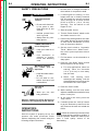
1. Be sure there is enough electrode in
the machine to complete the weld.
WARNING
ELECTRIC SHOCK
can kill.
• Do not touch electrically live parts or electrode with skin or wet
clothing.
3. Start the power source.
4. Turn the “Power Control” switch on the
wire feeder control to “On.”
• Always wear dry insulating gloves.
5. Position the welding head at the start
of the weld. Be sure the travel carriage
or other travel mechanism is set to
move in the proper direction.
FUMES AND GASES
can be dangerous.
•
Keep your head out of
fumes.
•
Use ventilation or
exhaust to remove
fumes from breathing
zone.
or
• Keep flammable material away.
• Do not weld on containers that have held
combustibles.
ARC RAYS
can burn.
•
6. Set the travel switch to “Automatic
Travel.” When set to “Hand Travel”,
the travel system operates without
welding.
7. For best starts, cut the electrode to a
sharp point.
8. Press the “Inch Down” button to feed
the electrode out of the nozzle.
a. For most applications, when hot
starting, leave the electrode
1/4 in. (6.4 mm) or more away
from the work.
b. When cold starting some
submerged arc welding, inch the
electrode down until it touches the
work and the flux valve opens.
9. Press the “Start” button.
Wear eye, ear, and
body protection.
Observe additional Safety Guidelines
detailed in the beginning of this manual.
Return to Master TOC
2. If submerged arc welding, fill flux
hopper with new or freshly screened
flux. All reused flux must be screened
100% through an 8 mesh screen
[0.065 to 0.075 in. (1.6 to 1.9 mm)
opening]. Turn the switch on the
hopper to “On.”
• Insulate yourself from
work or ground.
WELDING SPARKS
can cause fire
explosion.
Return to Section TOC
B-2
OPERATOR’S
INSTRUCTIONS
Once the system is properly set up, the
operator can make production welds
without readjusting the controls using the
following simple instructions:
NA-5
10. While welding, turn the cross seam
adjuster handwheel as needed to keep
the arc in the joint.
11. At the end of the weld, press the
“Stop” button.
12. If needed, press the “Inch Up” button
to get the electrode up and out of the
way. Remove the work and reload the
fixture.
NOTE: When the contact tip in the end of the
nozzle wears during repetitive welding, it
must be replaced. Check the contact tip for
wear if weld quality seems to be
deteriorating.
OPERATING INSTRUCTIONS
Return to Master TOC
Return to Section TOC
B-3
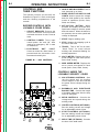
CONTROLS AND
THEIR FUNCTIONS
4. INCH UP AND INCH DOWN. Press to
inch electrode up or down.
The operator controls for the NA-5 are
illustrated in Figure B.1. Refer to the figure
and the following explanations of the
controls.
5. MODE SELECTOR SWITCH AND
LIGHTS. Used to preset the voltage
and wire feed speed for the various
modes of operation (Strike, Start,
Weld, and Crater).
EXPOSED CONTROLS (WITH
LOCKABLE COVER DOWN)
1. CIRCUIT BREAKER. Protects the
circuit from severe wire feed motor
overloads and short circuits. Press to
reset.
2. CONTROL POWER. Turns input
control power “On” and “Off.” Also
used as an emergency “Off” in case
of malfunction.
Return to Master TOC
Return to Section TOC
B-3
3. ELECTRODE
“HOT”
LIGHT.
Comes on when the “Start button” is
pressed and the electrode circuit
becomes electrically hot.
FIGURE B.1 – NA-5 CONTROLS.
6. SET-ACTUAL BUTTON. When
pressed, will display the actual wire
speed and voltage in the wire speed
and volts meters. When the button is
not pressed, the set wire speed and
voltage is displayed.
7. START. Begins welding cycle.
8. STOP. Initiates the stopping cycle at
the end of the weld.
9. TRAVEL. Turn to “Off” for no travel,
“Hand Travel” for travel without
welding, and “Automatic Welding” for
welding operations.
10. VOLTS METER. Displays the set or
actual voltage for each mode (Strike,
Start, Weld, Crater).
CONTROLS UNDER THE
LOCKABLE SECURITY COVER
Return to Master TOC
Return to Section TOC
11. WIRE SPEED METER. Displays the
set or actual wire speed for each
mode (Strike, Start, Weld, Crater).
11
10
17
16
15
13
7
Return to Master TOC
Return to Section TOC
12
3
1
6
9
14
2
4
5
NA-5
8
12. ARC STRIKING CONTROLS. Sets
the wire speed until the welding
current begins to flow and controls
the power source voltage during arc
striking.
13. BURNBACK AND ELECTRODE
BACKUP TIME. Controls the length
of burnback delay time after the stop
circuit is energized.
14. WELD CONTROLS. Controls the
voltage and wire speed during the
welding mode.
15. CRATER CONTROLS (OPTIONAL).
Sets the ending current and voltage
for an adjustable period of time.
16. START CONTROLS (OPTIONAL).
Sets the starting current and voltage
for an adjustable period of time.
17. WELD TIME (OPTIONAL). Controls
the time of the weld mode.
Return to Master TOC
Return to Section TOC
B-4
OPERATING INSTRUCTIONS
SETUP INSTRUCTIONS
Use the following steps to set up the NA-5
welding system prior to welding:
1. If using a multi-process power source
(SAM, DC-400, DC-600, DC-1000,
OR DC-1500 type), make connections and settings per the power
source connection diagram (Figures
A.8 to A.14) for the process being
used.
Return to Master TOC
Return to Section TOC
AUTO TAB
When using the NA-5 with the DC400 or CV-400 power source, the
auto tab jumper on the NA-5 voltage
PC board must be connected in order
for the inch down circuit to function.
When the auto tab jumper is
connected, the cold starting feature
of the NA-5 is disabled and only the
hot starting technique can be used. If
the cold start technique is to be used,
the optional Diode must be installed
on the DC-400 or CV-400.
2. Set the power source and NA-5
circuit polarity per information on
Electrode Polarity in Section A,
Installation.
Return to Master TOC
Return to Section TOC
3. Depending on the procedures and
applications, decide:
a. The means of arc striking and
whether to start the travel with
the “Start” button or the arc.
b. Whether the initial bead size or
penetration requires use of the
optional “Start Controls.”
See the Starting and Stopping
Sequences section.
4. Depending upon the procedures and
applications:
Return to Master TOC
Return to Section TOC
a. Select the arc and travel stopping
sequence. See the Starting and
Stopping Sequences section.
b. Decide if the control of the ending
bead size or crater fill requires
the use of optional “Crater
Controls”. See the Starting and
Stopping Sequences section.
NA-5
B-4
5. Set the head position relative to the
work as required for the fixture,
application, and procedures. See
IM305 Sec. T3.2.3.
6. Rotate the wire straightener, if used,
until the top of the straightener faces
the wire reel. This is required for
smooth feeding of the electrode into
the straightener.
7. Refer to the instructions for the wire
contact assembly being used. See
IM305 Sec. T2.2.6, T2.2.7, T2.5.3, or
T2.5.4.
8. The mount for standard 50 and 60 lb
(22.7 and 27.2 kg) electrode coils
includes a two-position brake
assembly. Generally the brake should
be at the inner position (nearest to
the wire reel shaft) for wire feed
speeds below 400 in./min (10 m/min).
It should be at the outer position for
faster wire speeds. To adjust the
brake position, remove the wire reel.
Pull the cotter pin that holds the
brake shoe to the arm, move the
shoe, and replace the cotter pin. Do
not bend the cotter pin — it is held in
place by a friction fit.
9. Load the wire reel per IM305 Sec.
T3.2.2 or install the Speed-Feed
drum or reel per Sec. T2.5.7-A or -B.
10. Straighten the first 6 in. (152.4 mm)
of electrode and push it through the
wire straightener to the drive rolls. To
use the cored wire straightener,
remove the knurled nut at the top and
feed the wire through the nut, down
through the straightener, and into the
drive rolls. Screw the nut back onto
the straightener. Feed the wire
through the nozzle tip and adjust
the straightener for optimum
straightness. With wire contact
assemblies, except the K231, adjust
until the electrode is straight as it
comes out of the nozzle. Do not
completely straighten the wire when
using the K231 contact nozzle
because the nozzle relies on the
small curvature of the electode for
proper electrical contact within the
contact tip.
Return to Master TOC
Return to Section TOC
B-5
OPERATING INSTRUCTIONS
11. Set the travel speed as specified by
the procedures. With the wire feeder
travel switch set to “Hand Travel”, the
travel runs without welding, permitting
accurate measurement of travel
speed. When using a Lincoln travel
carriage, adjust the speed with the
rheostat and the direction with the
toggle switch on the carriage control
panel.
Return to Master TOC
Return to Master TOC
Return to Master TOC
Return to Section TOC
Return to Section TOC
Return to Section TOC
12. Connect the work lead to the work or
a suitable piece of scrap. Clip the
end of the electrode to a sharp point.
13. Preset the “Start” (if used), “Weld”,
and “Crater” (if used) controls to the
wire speed and voltage specified in
the procedure.
14. Make several test welds, readjusting
the controls in the following order:
a. Set the “Arc Striking”, “Inch Wire
Speed”, and “Volts” controls for
optimum arc striking.
The
optimum strike control settings for
most processes will be typically 4
to 5 volts higher than the weld
mode voltage setting and 40% to
50% of the weld mode wire feed
speed setting (possibly lower if
cold starting is used).
b. If striking is still not satisfactory,
refer to the section on Setting
Travel Starting and Stopping or
IM305 Sec. T3.5.2 for information
on wire feed motor acceleration.
c. If installed, adjust the “Start
Controls” to set the welding
procedures for the time set on the
timer to provide the bead size,
penetration, or other factor as
needed for the application.
d. If installed, adjust the “Crater
Controls” to set the welding
procedures for the set time after
the “Stop” button is pressed to
provide the bead size or fill the
crater as needed for the
application.
e. Set the “Burnback
Time” to
provide the stopping characteristics needed.
NA-5
B-5
STARTING AND STOPPING
SEQUENCES
MEANS OF ARC STRIKING
The NA-5 Codes utilize “hot start” arc
striking which operates as follows:
1. With the electrode not touching the
work, press the “Start” button.
2. The electrically “hot” electrode
inches down as set by the “Inch Wire
Speed” control.
3. When the electrode makes contact
with the work, the arc strikes and the
circuit automatically switches from
“Strike” settings to “Weld” (or “Start”,
if used) settings.
NA-5 models above Code 8300 offer both
“hot start” arc striking, as described
above, or “Cold Start” arc striking which
operates as follows:
1. Press the “Inch Down” button until the
tip of the electrode touches the work,
automatically stops, and the flux (if
used) is automatically dispensed.
NOTE: If inch speed is set too high, the
electrode may stop with too much force on
its tip, resulting in possible poor starting.
2. The arc establishes when the “Start”
button is pressed, and the circuit
automatically switches to “Weld” (or
“Start”, is used) settings. Should the
arc not start immediately, the wire will
retract slightly until the arc is
established and then feed down in the
normal manner.
Use either the standard “on-the-fly” travel
starting or rewire the controls for “standstill”
travel starting as described in the Setting
Travel Starting and Stopping section.
Optional “Start Controls”
Recommended for applications where
penetration, bead size, and other
characteristics must be carefully controlled
at the start.
Return to Master TOC
Return to Section TOC
B-6
The starting sequence is as described above
except that when the arc strikes, the
machine welds at the wire speed and
voltage set by the “Start Controls” panel until
the time set on the thumbwheel switch
elapses. The circuit then automatically
switches to the “Welding Controls” wire
speed and voltage. Actual settings depend
on application requirements.
Available options for applications with
particularly difficult starting.
Return to Master TOC
1. K238 High Frequency Generator See IM305 Sec. T2.5.8.
Return to Section TOC
B-6
OPERATING INSTRUCTIONS
3. Any application for improved arc
striking.
“Standstill” Travel Starting
All models can be reconnected so the travel
remains at a standstill until the arc starts.
“Standstill” travel starting is used when the
electrode must be started at a precise
location.
For consistent arc striking with “Standstill”
travel starting, always clip the end of the
electrode to a sharp point before starting.
STOPPING SEQUENCES
SETTING TRAVEL
STARTING AND STOPPING
Standard machines can be connected for a
variety of starting and stopping sequences.
STARTING SEQUENCES
As shipped, the travel stops when the “Stop”
button is pressed, producing a small crater
area.
When the end of the weld overlaps the
beginning, changing the stopping sequence
to stop the travel later spreads the crater
over a longer area.
“On-the-Fly” Travel Starting
Return to Master TOC
Return to Section TOC
When shipped, all models are connected for
“On-the-Fly” travel starting. The starting
sequence is as follows:
1. With the electrode NOT touching the
work, press the “Start” button. This
starts both the wire feed and travel
motors.
2. When the electrically “hot” electrode
touches the work to start the arc,
there is relative motion between the
end of the electrode and the work.
This “scratching” type contact helps
assure consistent arc striking.
Return to Master TOC
Return to Section TOC
This sequence is recommended for most
welding applications including:
1. Roundabouts and any other weld
which ends at its starting point. A
K337 Weld Timer Module to control
the welding cycle duration can be
installed.
2. Welds started on a run-out tab.
NA-5
RECONFIGURING THE TRAVEL
SEQUENCES
WARNING
ELECTRIC SHOCK
can kill.
• Turn off input power to
the welding power source
using the disconnect
switch before working on
this equipment.
To change the travel sequence, turn off all
input power to the NA-5 control box. Open
the control box. The logic board is mounted
on the back of the box in the upper right
hand corner. To change the travel circuit for
the various modes of starting and stopping,
follow the information in the wiring diagram
for the NA-5 being used. Table B.1 also
shows information on reconfiguring the
travel sequences.
Return to Master TOC
Return to Section TOC
B-7
B-7
OPERATING INSTRUCTIONS
TABLE B.1 – TRAVEL SEQUENCE LEAD AND SWITCH POSITIONS.
Travel Starts
With “Start”
Button
Travel Stops
With “Stop”
Button
Older Models
Newer Models*
Lead #691 to Pin 6
Lead #692 to Pin 5
1
2
3
4
1
Switch #1
With Arc Striking With Arc Stopping
Lead #691 to Pin 6
Lead #692 to Pin 7
1
2
3
Return to Master TOC
Return to Section TOC
Lead #691 to Pin 5
Lead #692 to Pin 7
4
1
Return to Section TOC
Return to Master TOC
Return to Master TOC
2
3
With “Start”
Button
With “Start”
Button
With End Crater
Fill Time (With
optional procedure
module installed in
crater receptacle1)
Lead #691 to Pin 6
Lead #692 to Pin 9
After Burnback
Time (with
optional procedure
module installed
in crater
receptacle1)
Lead #691 to Pin 6
Lead #692 to Pin 8
1
2
3
4
1
2
3
4
1
4
1
*NOTE:
Indicates switch in up position
Indicates switch in down position
Indicates switch position does not matter
NA-5
3
4
2
3
4
2
3
4
Switch #2
Switch #1
DIP switch position 1 on switch #2 should be in the UP position as
shown. Additionally, remove 583C to 584C jumper plug from the pro
cedure board. If the procedure module is not installed, the switch
should be in the down position and the 583C to 584C jumper plug
should be reinstalled on the procedure board.
2
Switch #2
Switch #1
1
4
Switch #2
Switch #1
1If the optional procedure module is installed in the crater receptacle,
Return to Section TOC
1
3
Switch #2
Switch #1
With Arc Striking With Stop Button
2
2
3
Switch #2
4
Return to Master TOC
Return to Master TOC
Return to Section TOC
Return to Section TOC
B-8
OPERATING INSTRUCTIONS
Wire Feed Motor Acceleration
The standard stopping sequence when the
optional “Crater Controls” are not used is as
follows:
WARNING
1. Press the “Stop” button.
ELECTRIC SHOCK
can kill.
2. The wire feed motor stops and the
“Burnback Time Delay” starts.
• Turn off input power to
the welding power source
using the disconnect
switch before working on
this equipment.
3. The arc continues to burn the
electrode back from the puddle until
the arc goes out or the time set on the
thumbwheel switch elapses. This
control should be set for just enough
burnback time to prevent crater
sticking.
The NA-5 has two different speeds of
controlled wire feed motor acceleration. As
shipped, the unit is connected for fast
acceleration which is best for most
applications. To change to the slower
acceleration, turn off all input power to the
NA-5 control box. Open the control box.
Locate the Control PC Board mounted on
the back of the box in the lower right hand
corner. Change the jumper plug from the “F”
pin to the “S” pin as shown in Figure B.2.
FIGURE B.2 – ACCELERATION
JUMPER PLUGS.
Return to Master TOC
JUMPER
PLUG
Return to Section TOC
B-8
There are two other ways this circuit can be
connected. One will cause the wire to
retract* with a contactor drop out delay at
the end of the weld. The second will cause
the wire to retract* during burnback time,
and there will be no contactor drop out delay
at the end of the weld. If either one of these
alternate methods of stopping the weld is
desired, the connections on the logic board
can be easily changed.
To change the stopping sequence, turn the
input AC power off at the power source,
remove the screw holding the inner panel,
and swing the panel open. Change the
connections (older models) or switch
positions (newer models) on the logic board
as shown in Table B.2.
Optional “Crater Controls”
This option is recommended for applications
where the ending bead size must be
controlled, applications when the crater must
be filled, roundabouts, and any other welds
where the end overlaps the start.
Return to Master TOC
Return to Section TOC
When the “Stop” button is pressed, the
machine welds at the wire speed and
voltage set by the “Crater Controls” until the
time set on the thumbwheel switch elapses.
The circuit then automatically switches to the
arc stopping sequence described above.
Burnback and Electrode Backup
The primary consideration in setting the arc
stopping sequence is to prevent the
electrode from sticking in the puddle. This
is easily done with the machine as shipped.
NA-5
NOTE: Setting crater time to 0.00 seconds
will give zero crater time; however, the
crater settings will be active during
burnback time until the arc goes out.
*Wire will retract at weld mode speed (or crater mode
speed, if installed) until the arc goes out and then retract
at strike mode speed for the remainder of burnback
time.
Return to Master TOC
Return to Master TOC
Return to Section TOC
Return to Section TOC
B-9
TABLE B.2 – STOPPING SEQUENCE SETTINGS.
When “Stop” Button
is Pressed
Older Models
Feed motor stops and
electrode burns back with
contactor delay (standard)
Lead #693 to Pin 3
Lead #690 to Pin 4
Feed motor inches up and
electrode burns back with
contactor delay
Lead #693 to Pin 1
Lead #690 to Pin 4
Feed motor inches up and
contactor opens
(no burnback)
Lead #693 to Pin 1
Lead #690 to Pin 2
Return to Master TOC
Newer Models*
1
2
3
1
2
3
1
2
3
4
Switch #2
*NOTE:
Indicates switch in up position
Indicates switch in down position
Indicates switch position does not matter
FIGURE B.3 – VOLTAGE CONTROL
RESPONSE JUMPER PLUG
LOCATIONS.
The NA-5 is provided with selectable voltage
control response. Proper setting depends on
the power source and process being used.
Refer to the appropriate power source
connection diagram for the proper
connection of the jumpers located on the
NA-5 Voltage P.C. Board, shown in Figure
B.3.
RED
JUMPER
PLUG
To change the voltage control response:
1. Turn off all input power to the NA-5
control.
WHITE
JUMPER
PLUG
3. Locate the Voltage P.C. Board
mounted on the right side of the box.
Position the jumper plugs on the
Voltage P.C. Board per the
appropriate power source connection
diagram.
NA-5
B
D
A
NA-5
VOLTAGE
Return to Master TOC
4
Switch #2
2. Open the control box.
Return to Section TOC
4
Switch #2
VOLTAGE CONTROL
RESPONSE
Return to Section TOC
B-9
OPERATING INSTRUCTIONS
Return to Master TOC
Return to Section TOC
B-10
OPERATING INSTRUCTIONS
AUTOMATIC SHUTDOWN
If the NA-5 voltage control is unable to
supply the “Set” value of the arc voltage
while welding, the automatic shutdown
circuit will activate. This protection circuit
immediately returns the NA-5 control to idle
state within a few seconds after the arc
voltage discrepancy occurs.
Typical causes that activate this protective
shutdown circuit are as follows:
Return to Master TOC
Return to Master TOC
Return to Master TOC
Return to Section TOC
Return to Section TOC
Return to Section TOC
1. “Set” value of arc voltage is outside
the power source range.
2. Power source voltage control not set
for “Remote”.
3. Misconnection of NA-5 control cable
leads to the power source.
4. Incorrect weld polarity connections, or
settings, at NA-5 or power source.
5. Lost connection of NA-5 voltage
sensing leads (#67 and #21) between
arc and voltage control or a blown 1/8
amp fuse on voltage PC boards built
since 1983.
With NA-5 units above Code 8300, the
conditions of causes 4 and 5 above would
result in the wrong wire feed direction when
the weld is started. See the section on Cold
Start Circuitry.
In the case of full-range control power
sources, such as the DC-600, this protective
shutdown circuit could prevent welding
under the conditions of causes 3, 4 and 5
above by holding the power output at
minimum, possibly providing too low of a
power source output to even establish an
arc, or causing the field fuse to blow
because of rapid field reversals with NA-5
controls above Code 8300. See the section
on Cold Start Circuitry.
Although out of range shutdown can occur
with all power sources when working with
very low or very high arc voltages, it is most
NA-5
B-10
likely to occur when using the R3S models
with the somewhat limited voltage ranges of
the various taps. For instance, if the R3S400 triangle tap setting is for 31 volts, the
range of control from the remote circuit is
approximately 7 volts, i.e. 27.5 to 34.5 volts
at nominal input voltage. If the NA-5
controls are set for 29 volts, and the input
voltage to the R3S goes up, it may not be
possible for the NA-5 control circuit to hold
the 29 volts, so the welding will shut down.
By changing to the 27 volt triangle setting,
the range will be approximately 23.5 to 30.5
volts, and at high input voltage, there will be
sufficient control to hold the “Set” arc
voltage. On these machines, if the NA-5
stops welding, follow this procedure:
1. Move the NA-5 voltage set point 2
volts lower than the desired
procedure and make a test weld.
a. If the NA-5 still shuts down, go to
step 2 below.
b. If the NA-5 keeps welding,
change the R3S triangle setting
to the next higher voltage and
reset the NA-5 set point to the
desired procedure. The R3S is
now set properly unless there is
a significant change in input
voltage. Skip the following step.
2. Move the NA-5 voltage setting set
point 2 volts higher than the desired
procedure and make a test weld.
a. If the NA-5 keeps welding,
change the R3S triangle setting
to the next lower voltage and
reset the NA-5 set point to the
desired procedure. The R3S is
now set properly unless there is
a significant change in input
voltage. Skip the following step.
b. If the NA-5 still shuts down, refer
to the following paragraph and
other causes previously listed.
Return to Master TOC
Return to Master TOC
Return to Section TOC
Return to Section TOC
B-11
OPERATING INSTRUCTIONS
In some cases, it is also possible to hold the
“Actual” button pressed while starting the
arc. Before the NA-5 shuts down, the actual
arc voltage can be read on the digital meter.
Comparing this reading to the “Set” reading
will tell what change in the range controls of
the power source are required so it can
supply the desired voltage. Should the
meter read zero, check the NA-5 sensing
leads (#21 and #67) connections. Should
the meter read negative (-) voltage, the
polarity connections or settings at the NA-5
or power source are wrong.
This same general procedure can be used
on the other power sources. For example,
if the NA-5 keeps shutting down and the
other possible causes have been checked,
adjust the “Set” voltage higher and/or lower
than the desired voltage. If the NA-5
continues to weld at one of these voltages,
it can be determined what change in the
range controls of the power source are
required so it can supply the desired voltage.
Return to Master TOC
Return to Section TOC
COLD START CIRCUITRY
NA-5 controls above Code 8300 contain
circuitry added to the voltage PC board to
facilitate the “cold starting” features of these
units.* This circuitry senses the voltage
present between the electrode and work, via
leads #67 and #21, and permits normal wire
feed if this voltage exceeds approximately
6.5 VDC. However, if this voltage level is
not exceeded, or drops below approximately
3.5 VDC, the “Auto Stop” activates while
inching down or electrode backup occurs if
the arc start circuit has been initiated.
*Units below Code 8300 can be provided with the cold
start circuitry by replacing the old L-6257 voltage board
with the new G-1556 voltage board. This new board
will mount and connect in the same manner as the old
board, except the third harness connector (previously
connected to a jumper plug) must be connected to the
lower receptacle of the new voltage board.
Return to Master TOC
Return to Section TOC
NOTE: HI-FREQ starting cannot be used
with converted units below Code 8300.
NA-5
B-11
A. Auto Stop
When the “Inch Down” button is pressed, a
low-level DC voltage signal is applied
between the electrode and work which
permits the wire to inch down normally.
When the electrode makes electrical contact
with the work, it shorts out this signal
causing the wire feed to automatically stop
and the flux solenoid to activate until the
“Inch Down” button is released. The “Inch
Up” button is not affected by this circuit.
B. Electrode Backup
If while starting or welding the electrode
stubs or shorts to work, the resulting loss of
arc voltage will cause the electrode to
momentarily back up until the arc voltage is
re-established and then change back to the
normal feed direction.
NOTE: The “cold starting” circuitry will
cause the NA-5 to feed in the wrong
direction when the “Start” button is pressed
if the “Actual” arc voltage, as read on the
NA-5 voltmeter, does not exceed typically
about 6.5 volts. Usual causes for the
situation are:
1. No wire loaded through the NA-5
head and nozzle assembly (except
when using the K148 Contact
Nozzle).
2. No power source weld cable
connection to the NA-5 head or work.
3. Incorrect
electrode
polarity
connections at the NA-5 or power
source.
4. Little or no output voltage from the
power source.
5. An open voltage sensing lead #67 or
#21 to the NA-5 control box or a
blown 1/8 amp fuse on a voltage PC
board built since 1983.
Return to Master TOC
Return to Section TOC
B-12
OPERATING INSTRUCTIONS
SECURITY OF WELD
PROCEDURE SETTINGS
There are two means provided to prevent or
limit unauthorized readjustment of the NA-5
voltage and wire feed speed controls once
set to the desired procedure.
Return to Master TOC
Return to Section TOC
1. The security panel of the NA-5 can be
locked to prevent access to the
control knobs.
2. The control range of the procedure
control knobs can be limited to either
about 3% or about 15% of the full
range control by installing a knob
rotation stop screw to any or all of the
control knobs. This stop screw is
installed in the following manner:
Return to Section TOC
Return to Master TOC
Return to Section TOC
Return to Master TOC
beneath each square so the head
is on the back side of the panel
(inside the control box).
f.
h. Turn on the NA-5 input power and
set the desired procedure by
rotating the shafts of the controls.
i.
Carefully replace each control
knob so the #4 screw inserts into
the center of the shorter length
channel on the back of the knob
for about 3% of the total range of
control or into the center of the
longer length channel for about
15% of the total range of control.
j.
With finger pressure on the knob
against the felt seal, carefully
retighten the set screw of each
knob.
b. Loosen each knob set screw and
remove all knobs, including the
rotary select switch knob.
d. Open
the
control
box.
Disconnect, then remove, the
procedure control PC board
assembly and its panel insulation.
e. Install a 1/2 in. long, pan or round
head, #4 sheet metal screw into
the 0.10 in. diameter hole located
NA-5
Remount the PC board assembly
and its panel insulation.
Reconnect the PC board and
close and secure the control box.
g. Remount the rotary select switch
knob and replace each square
spacer tube and felt seal so the
#4 screw protrudes between the
tube and the felt seal.
a. Turn off the input power to the
NA-5.
c. Remove the felt seal and square
spacer tube mounted behind
each control knob.
B-12
NOTE: Steps h thru j will have to be
repeated if it is desired to change the
procedure settings to values outside the
selected 3% or 15% control range limit.
TABLE OF CONTENTS
- ACCESSORIES SECTION -
Accessories . . . . . . . . . . . . . . . . . . . . . . . . . . . . . . . . . . . . . . . . . . . . . . . Section C
General . . . . . . . . . . . . . . . . . . . . . . . . . . . . . . . . . . . . . . . . . . . . .
C-2
Listing of Accessories . . . . . . . . . . . . . . . . . . . . . . . . . . . . . . . . . . .
C-3
K29 Vertical Lift Adjuster . . . . . . . . . . . . . . . . . . . . . . . . . . . . . .
C-3
K58 Magnetic Separator . . . . . . . . . . . . . . . . . . . . . . . . . . . . . .
C-3
K96 Horizontal Adjuster . . . . . . . . . . . . . . . . . . . . . . . . . . . . . . .
C-3
K129 Submerged Arc Small Wire Twinarc® . . . . . . . . . . . . . . . . .
C-3
K148 Contact Nozzle and K149 Linc-FillTM
Long Stickout Extension . . . . . . . . . . . . . . . . . . . . . . . . . . . . .
C-3
K218 Horizontal Fillet/Lap Attachment . . . . . . . . . . . . . . . . . . . .
C-3
K219 Flux Hopper Kit . . . . . . . . . . . . . . . . . . . . . . . . . . . . . . . .
C-3
K223 Solenoid Kit . . . . . . . . . . . . . . . . . . . . . . . . . . . . . . . . . . .
C-3
K225 Submerged Arc Twinarc Kit . . . . . . . . . . . . . . . . . . . . . . .
C-4
K238 High Frequency Unit . . . . . . . . . . . . . . . . . . . . . . . . . . . .
C-4
K239 Twinarc Kit for Innershield® Electrodes . . . . . . . . . . . . . . .
C-4
K278 SpreadarcTM . . . . . . . . . . . . . . . . . . . . . . . . . . . . . . . . . . .
C-4
K281 Solid Wire Straightener for Tiny Twinarc . . . . . . . . . . . . . .
C-4
K285 Concentric Flux Cone . . . . . . . . . . . . . . . . . . . . . . . . . . . .
C-4
K310 Flux Screen . . . . . . . . . . . . . . . . . . . . . . . . . . . . . . . . . . .
C-4
K325 TC-3 Travel Carriage . . . . . . . . . . . . . . . . . . . . . . . . . . . .
C-4
K334 Start and Crater Controls . . . . . . . . . . . . . . . . . . . . . . . . .
C-5
K336 Remote Interface Module . . . . . . . . . . . . . . . . . . . . . . . . .
C-5
K337 Weld Timer Module . . . . . . . . . . . . . . . . . . . . . . . . . . . . .
C-5
K349 Multi-Procedure Kit . . . . . . . . . . . . . . . . . . . . . . . . . . . . . .
C-5
S-22022 or S-22182 Current Relay . . . . . . . . . . . . . . . . . . . . . .
C-5
Speed-Feed Drum . . . . . . . . . . . . . . . . . . . . . . . . . . . . . . . . . .
C-5
Speed-Feed Reel . . . . . . . . . . . . . . . . . . . . . . . . . . . . . . . . . . .
C-5
Return to Master TOC
Return to Master TOC
Return to Master TOC
Return to Master TOC
Section C
NA-5
Section C
Return to Master TOC
Return to Master TOC
Return to Master TOC
Return to Master TOC
Return to Section TOC
Return to Section TOC
Return to Section TOC
Return to Section TOC
C-2
ACCESSORIES
C-2
GENERAL
This section contains a listing and short
description of the accessories that are
available with the NA-5 automatic welding
system.
TABLE C.1 – NA-5 AUTOMATIC WELDING SYSTEM ACCESSORIES.
Product Number
Product Name
K29
VERTICAL LIFT ADJUSTER
K58
MAGNETIC SEPARATOR
K96
HORIZONTAL ADJUSTER
K129
SUBMERGED ARC SMALL WIRE TWINARC
K148
CONTACT NOZZLE
K149
LINC-FILL LONG STICKOUT EXTENSION
K218
HORIZONTAL FILLET/LAP ATTACHMENT
K219
FLUX HOPPER KIT
K223
SOLENOID KIT
K225
SUBMERGED ARC TWINARC KIT
K238
HIGH FREQUENCY UNIT
K239
TWINARC KIT FOR INNERSHIELD ELECTRODES
K278
SPREADARC
K281
SOLID WIRE STRAIGHTENER FOR TINY TWINARC
K285
CONCENTRIC FLUX CONE
K310
FLUX SCREEN
K325
TC-3 TRAVEL CARRIAGE
K334
START AND CRATER CONTROLS
K336
REMOTE INTERFACE MODULE
K337
WELD TIMER MODULE
K349
MULTI-PROCEDURE KIT
S22022 or S22182
CURRENT RELAY
SPEED-FEED DRUMS
SPEED-FEED REELS
NA-5
Return to Master TOC
Return to Master TOC
Return to Master TOC
ACCESSORIES
C-3
K29 VERTICAL LIFT ADJUSTER
K148 CONTACT NOZZLE AND
K149 LINC-FILLTM LONG
STICKOUT EXTENSION
When mounted in the NA-5 head mounting
system, the K29 Vertical Lift Adjuster
provides quick hand crank adjustment of the
vertical head position. It also has some
horizontal adjustability as described in Sec.
T3.2.3 of operator’s manual IM305.
Installation instructions are shipped with
each K29 Vertical Lift Adjuster kit, are
contained in the IM305 manual, and can be
ordered as Sec. T2.2.11.
This Innershield and submerged arc nozzle
is designed for 0.062 through 3/16 in.
(1.57 through 4.76 mm) wire at high
currents. When long stickout [2 to 5 (50.80
to 127.00 mm)] is required, the K149
Linc-Fill Long Stickout Extension is
recommended along with the K237 Linc-Fill
Starting Relay. Instructions are contained in
the IM305 manual and can also be ordered
as Sec. T2.2.7.
K58 MAGNETIC SEPARATOR
K218 HORIZONTAL
FILLET/LAP ATTACHMENT
LISTING OF ACCESSORIES
Useful with any submerged arc equipment.
The unit removes foreign magnetic particles
from reused submerged arc welding flux.
Operating instructions are included with the
kit.
K96 HORIZONTAL ADJUSTER
When mounted in the NA-5 head mounting
system, the K96 Horizontal Adjuster
provides quick hand crank adjustment of the
horizontal head position. Installation
instructions are shipped with each K96
Horizontal Adjuster kit, are contained in the
IM305 manual, and can be ordered as Sec.
T2.2.12.
K129 SUBMERGED ARC SMALL
WIRE TWINARC®
The Twinarc system provides for the feeding
of two small solid wires through a single wire
feeder. The Twinarc assembly includes a
wire reel, reel brake, shaft and mounting
bracket, drive roll, idle roll assembly, dual
wire guides, and nozzle and contact tip or
contact tip holder. Instructions are shipped
with each kit, are contained in the IM305
manual, and can be ordered as Sec. T2.5.3
K129.
Return to Master TOC
Return to Section TOC
Return to Section TOC
Return to Section TOC
Return to Section TOC
C-3
NA-5
This special contact assembly automatically
guides the electrode when making
submerged arc horizontal fillet and lap welds
to ensure accurate bead placement without
expensive fixtures and clamps. Installation,
operating, and maintenance instructions are
shipped with each kit, are contained in the
IM305 manual, and can also be ordered as
Sec. T2.5.4.
K219 FLUX HOPPER KIT
This flux hopper, which has an electric flux
valve, can be mounted on NA-5N and
NA-5NF heads for submerged arc welding.
Installation instructions are included with
each kit. The operator and maintenance
instructions are contained in the IM305
manual and can also be ordered as
Sec. T2.5.9.
K223 SOLENOID KIT
The solenoid kit includes a valve to control
water flow when using the cooling
attachment on the K148 or K239 contact
nozzle assembly. It opens when the start
button is pressed and can be wired to close
either when the stop button is pressed or
when the arc goes out. Installation
instructions are shipped with each kit.
Return to Master TOC
Return to Master TOC
Return to Section TOC
Return to Section TOC
C-4
ACCESSORIES
K225 SUBMERGED
ARC TWINARC KIT
The Twinarc kit provides for the feeding of
two 5/64, 3/32, or 1/8 in. (1.98, 2.38, or
3.18 mm) solid wires through a single wire
feeder. The electrode wire must be the
same size. The assembly includes a wire
reel, insulated reel mounting bracket, wire
straightener, dual wire guides, nozzle, and
contact block. Installation, operating, and
maintenance instructions are shipped with
each kit, are contained in the IM305 manual,
and can be ordered as Sec. T2.5.3 K225.
K238 HIGH FREQUENCY UNIT
This unit supplies high frequency to the
welding leads for more positive starts, which
may be required for certain difficult starting
applications. Factory-installed insulation is
required. Instructions are shipped with each
unit. Installation instructions are contained
in the IM305 manual and can be ordered as
Sec. T2.5.8.
Return to Master TOC
Return to Section TOC
K239 TWINARC KIT FOR
INNERSHIELD® ELECTRODES
This kit provides for welding with two
Innershield electrodes. Two 3/32 in.
(2.38 mm) flux-cored electrodes are fed
through a single wire feeder. Both wires
must be the same size. The K239 kit
includes the nozzle equipped for water
cooling, drive rolls, drive roll locating collar,
idle roll assembly, ingoing and outgoing
guide tubes, wire straightener, wire reel, and
wire reel mounting shaft and insulation.
Instructions are included in the kit, are
contained in the IM305 manual, and can
also be ordered as Sec. T2.5.3 K239.
Return to Master TOC
Return to Section TOC
K278 SPREADARC TM
C-4
arc, and submerged arc procedures can be
used. Instructions are shipped with the kit,
are contained in the IM305 manual, and can
also be ordered as Sec. T2.5.6.
K281 SOLID WIRE
STRAIGHTENER FOR
TINY TWINARC
This wire straightener will straighten 0.045
through 3/32 in. (1.14 through 2.38 mm) wire
diameters. It is recommended for welding
procedures requiring long stickout and
where wire position accuracy is essential.
Instructions are shipped with the kit, are
contained in the IM305 manual, and can be
ordered as Sec. T2.5.5.
K285 CONCENTRIC FLUX CONE
The concentric flux cone was designed to
fit on the K148 Contact Nozzle alone, the
K148 Contact Nozzle with a K149 Linc-Fill
Long Stickout Extension, the K129
Submerged Arc Small Wire Twinarc, and
the K391 nozzles. (The maximum electrical
stickout when using the K149 Linc-Fill Long
Stickout Extension will be 4 in. [101.6 mm.]).
Use of this attachment results in the flux
being fed concentrically around the
electrodes.
Installation, operating, and
maintenance instructions are shipped with
each kit, are contained in the IM305 manual,
and can be ordered as Sec. T2.2.8 K285.
K310 FLUX SCREEN
Useful for any submerged arc equipment. It
removes foreign magnetic particles from
reused submerged arc welding flux.
Operating instructions are included in the kit.
K325 TC-3 TRAVEL CARRIAGE
The primary application for this accessory is
for hardfacing buildup using a Twinarc
nozzle. The combination “SpreadarcTwinarc” covers large areas quickly with
smooth beads of minimum admixture with
the base metal. Flux cored electrode, open
NA-5
The K325 Travel Carriage carries the control
box and wire drive head, in either direction,
on a beam of suitable length and
mechanical specifications. Two models are
available: Standard and High Capacity.
Return to Master TOC
Return to Section TOC
C-5
ACCESSORIES
K334 START AND CRATER
CONTROLS
S22022 OR S22182 CURRENT
RELAY MODULES
Easily installed procedure and timer boards
to permit adjustment of wire speed and
voltage. Can be installed to function at
either the start of the weld or at the end for
crater filling. Installation, operating, and
maintenance instructions are shipped with
each kit and can be ordered as Sec. T2.5.13
K334.
The current relay is useful to fixture builders
and others who need a signal indicating that
welding current is flowing. Installation,
operating, and maintenance instructions are
shipped with each kit. The S22022 relay
module is suitable for dry circuit applications
and it is rated at 2 Amps, 115 VAC or 28
VDC. This relay has both normally open and
normally closed contacts. The S22182 relay
module is suitable for applications requiring
at least 10 mA current and it is rated at 3
Amps, 115 VAC or 28 VDC. This relay only
has normally open contacts.
Return to Master TOC
Return to Master TOC
Return to Master TOC
Return to Section TOC
Return to Section TOC
K336 REMOTE INTERFACE
MODULE
Return to Section TOC
C-5
Permits connection of customer-furnished
remote start-stop and inch momentary
contact closure or momentary 24 volt
signals. Also used when a single remote
signal is desired to start or stop multiple
heads. This module replaces the earlier
K336 Remote Pushbutton Interface Module.
Installation and application instructions are
shipped with each kit and can be ordered as
Sec. T2.5.11 K336.
SPEED-FEED DRUM
These drums must be set on a turntable
which permits them to freely turn in a
clockwise direction. Installation, operating,
and maintenance instructions are contained
in the IM305 manual and can be ordered as
Sec. T2.5.7-A.
K337 WELD TIMER MODULE
SPEED-FEED REEL
Permits setting of weld time for an adjustable
period. Eliminates need to press the “Stop”
button. Instructions are included in the kit.
These reels require dereeling equipment
that permits the reel to rotate freely as the
electrode is used. Installation, operating,
and maintenance instructions are contained
in the IM305 manual and can be ordered as
Sec. T2.5.7-B.
K349 MULTI-PROCEDURE KIT
The K349 Multi-Procedure Kit provides three
additional weld mode procedure settings of
wire feed speed and voltage, allowing the
choice of four NA-5 weld mode procedures.
Installation, operating, and maintenance
instructions are shipped with each kit, are
contained in the IM305 manual, and can be
ordered as Sec. T2.5.19 K349.
NA-5
Return to Section TOC
Return to Master TOC
Return to Section TOC
Return to Master TOC
Return to Master TOC
Return to Section TOC
Return to Master TOC
Return to Section TOC
C-6
NOTES
NA-5
C-6
Section D
TABLE OF CONTENTS
- MAINTENANCE SECTION -
Maintenance . . . . . . . . . . . . . . . . . . . . .
Control Box . . . . . . . . . . . . . . . . . . .
General . . . . . . . . . . . . . . . . . . .
Circuit Protection . . . . . . . . . . . .
Ground Fault Fuse Protection . . .
Welding Head . . . . . . . . . . . . . . . . . .
Wire Drive Gear Box . . . . . . . . . .
Wire Drive Motor . . . . . . . . . . . .
Changing Wire Feed Gear Ratios .
Wire Drive Mechanism . . . . . . . .
Wire Straighteners . . . . . . . . . . .
Optional Features . . . . . . . . . . . . . . .
Contact Assemblies . . . . . . . . . . .
Wire Reel Mounting for 50 or 60 lb
Travel Carriage . . . . . . . . . . . . . .
Vertical Lift Adjuster . . . . . . . . . .
Horizontal Adjuster . . . . . . . . . . .
High Frequency Generator . . . . .
Spreadarc . . . . . . . . . . . . . . . . . .
..........
..........
..........
..........
..........
..........
..........
..........
..........
..........
..........
..........
..........
(22.7 or 27.2
..........
..........
..........
..........
..........
Return to Master TOC
Return to Master TOC
Return to Master TOC
Return to Master TOC
Section D
NA-5
........
........
........
........
........
........
........
........
........
........
........
........
........
kg) Coils
........
........
........
........
........
.
.
.
.
.
.
.
.
.
.
.
.
.
.
.
.
.
.
.
.
.
.
.
.
.
.
.
.
.
.
.
.
.
.
.
.
.
.
.
.
.
.
.
.
.
.
.
.
.
.
.
.
.
.
.
.
.
.
.
.
.
.
.
.
.
.
.
.
.
.
.
.
.
.
.
.
. Section D
.
D-2
.
D-2
.
D-2
.
D-3
.
D-3
.
D-3
.
D-4
.
D-4
.
D-5
.
D-5
.
D-6
.
D-6
.
D-6
.
D-6
.
D-6
.
D-6
.
D-6
.
D-6
Return to Master TOC
Return to Section TOC
D-2
D-2
MAINTENANCE
CONTROL BOX
GENERAL
Inspect the control box every 3 months. If
needed, blow dirt out using low pressure air.
No further maintenance should be required.
If a complete or partial short occurs in the
field circuit, or if there is a defect on the PC
board, a 1/2 amp slow-blow type fuse will
blow. This field circuit fuse is mounted on the
power PC board, shown in Figure D.2, inside
the control box. Before replacing the fuse,
check the motor field for a short condition.
Normal resistance is approximately 700
ohms.
Return to Section TOC
Return to Master TOC
Return to Section TOC
Return to Master TOC
CIRCUIT PROTECTION
The circuit breaker mounted on the left side
of the control box protects the control circuit
from short circuit conditions and from severe
wire feed overloads. If it is open, determine
and correct the cause for the overload. To
reset the circuit breaker, push in the red
button shown in Figure D.1.
FIGURE D.1 – CIRCUIT BREAKER
RESET BUTTON.
With NA-5 controls above Code 8300, the
field circuit fuse may blow due to frequent
motor field reversals from application
problems affecting the “cold” starting circuit,
such as the power source output being too
low to establish an arc or the welding
procedure causing frequent electrode-topuddle shorting. (Refer to Automatic
Shutdown in Section B, Operating
Instructions.)
FIGURE D.2 – POWER PC BOARD
FUSE LOCATIONS.
NA-5 POWER
Return to Master TOC
Return to Section TOC
POWER
1/2 AMP
SLOW-BLOW
FUSE
FIELD
1/2 AMP
SLOW-BLOW
FUSE
The power supply for the electronic circuitry
is protected by a 1/2 amp slow-blow type fuse
shown in Figure D.2. It is located on the
power PC board inside the control box.
CIRCUIT
BREAKER
RESET BUTTON
NA-5
Return to Master TOC
Return to Section TOC
D-3
The 1/8 amp fast-blow fuse, shown in Figure
D.3, on a voltage PC board built since 1983,
protects the NA-5 circuitry from damage
which may result from a ground or case
faulted control lead. If the fuse blows, the
NA-5 voltage sensing lead circuit will be
opened (Refer to Automatic Shutdown in
Section B, Operating Procedures) and the
Troubleshooting Guide.
NA-5 circuit common (#510). Such a
condition typically exists when the NA-5
polarity connections are set for electrode
negative.
FIGURE D.3 – VOLTAGE BOARD FUSE
LOCATION.
Once a year, recoat all gear teeth with a
non-fluid molydisulfide type grease such as
Non-Fluid Oil Corporation’s A-29 Special/MS
Lubricant. For access to the gears in the first
chamber, remove the adapter plate and
motor assembly as shown in Figure D.4.
Return to Master TOC
1/8 AMP
FAST-BLOW
FUSE
Return to Section TOC
D-3
MAINTENANCE
WELDING HEAD
WIRE DRIVE GEAR BOX
FIGURE D.4 – WIRE DRIVE MOTOR
GEAR BOX.
DRIVE MOTOR
BRUSH ACCESS
HEX HEAD
SCREW
Return to Master TOC
FIRST
CHAMBER
PIPE
PLUG
NA-5
VOLTAGE
Return to Section TOC
ADAPTER
PLATE AND
MOTOR
ASSEMBLY
Return to Master TOC
Return to Section TOC
GROUND FAULT FUSE
PROTECTION
WIRE DRIVE
GEARBOX
SECOND
CHAMBER
SLOT HEAD
SCREW
A 1/8 amp fast-blow fuse, shown in Figure
D.3, is located on the voltage PC board.
This fuse will protect the NA-5 circuitry from
damage resulting from a ground or case
faulted control lead when the arc voltage
potential exists between ground and the
NA-5
To lubricate the gears in the second
chamber, remove one of the pipe plugs and
feed grease until it comes in contact with the
bevel gear teeth. Then, rotate the output
shaft by hand until all teeth are lubricated.
Return to Master TOC
Return to Section TOC
D-4
WIRE DRIVE MOTOR
FIGURE D.5 – CHANGING THE WIRE
FEED GEAR RATIO
Periodically inspect the wire drive motor
brushes, Figure D.4. Replace the brushes
as needed.
CHANGING WIRE FEED GEAR
RATIOS
Return to Master TOC
Return to Master TOC
Return to Section TOC
Four wire size conversion kits are available
to modify the wire feeder for different size or
type electrodes. The kits include drive rolls
and guide tubes for the wire specified, as
shown in Table D.1.
Return to Section TOC
D-4
MAINTENANCE
TABLE D.1 - CONVERSION
HEX NUT (11)
PLAIN WASHER (9)
SLOT HEAD
SCREWS
WIRE (MOUNTING
SCREWS)
FEED
GEARBOX
KITS
Wire Type in. (mm)
Conversion Kit
3/32-7/32 (2.38-5.56)
Solid or Cored
T13724-A
1/16-3/32 (1.59-2.38)
Solid or Cored
T13724-B
0.035-0.052 (0.89-1.32)
Solid
T13724-C
0.045-0.052 (1.14-1.32)
Cored
T13724-D
Refer to Table D.2. Four gear ratios are
available: 21:1, 57:1, 95:1, and 142:1. To
change the gear ratio, replace the motor
pinion and the first reduction gear per the
following instructions (Refer to Figures D.4,
D.5 and D.6).
NOTE: Any item numbers in parentheses
on Figure D.5 refer to item numbers in the
task description breakdown.
INPUT
HELICAL
GEAR (12)
WOODRUFF
KEY (8)
1. Remove the four screws that mount
the adapter plate and motor assembly
to the gear box. Remove the adapter
plate and motor assembly from the
gear box.
2. Take the two long screws removed in
step 1 and screw one into each of the
tapped holes located on the face of
fiber input helical gear (12). Insert the
screws through the full thickness of
the gear, and using a screwdriver
wedged between the screws to
prevent rotation, remove hex nut (11)
that holds the gear to the shaft.
Remove plain washer (9).
Return to Master TOC
Return to Section TOC
TABLE D.2 – WIRE FEED GEAR RATIOS.
Gear
Ratio
Feed Speed
Range
in/min (m/min)
21:1
100-2070 (2.54-52.58)
0.052 (1.3)
0.052 (1.3)
57:1
40-778 (1.02-19.76)
3/32 (3.0)
1/16 (1.6)
95:1
22-456 (0.56-11.58)
5/32 (4.0)
1/8 (3.2)
142:1
15-300 (0.38-7.62)
5/32 (4.0)
7/32 (5.6)
NA-5
Max Wire Size
in. (mm)
Cored Wire
Solid Wire
Return to Master TOC
Return to Master TOC
Return to Master TOC
Return to Section TOC
Return to Section TOC
Return to Section TOC
D-5
3. Pull the gear from the shaft using the
screws as a pulling device.
4. Be certain woodruff key (8) is properly
located on the shaft. Screw the
adapter plate and motor assembly
mounting screws into the new fiber
input helical gear from the stenciled
side and place the gear on the shaft.
Replace plain washer (9), tighten the
hex nut (1), and remove the adapter
plate and motor assembly mounting
screws from the gear.
5. After noting the relation of the adapter
plate with the motor leads, remove
the adapter plate from the wire drive
motor. See Figure D.6. Support the
pinion properly and, with the proper
size punch, drive the roll pin that
holds the pinion out of the shaft. Pull
the pinion off. Install the new pinion
and replace the roll pin. Replace the
adapter plate in its original location.
6. Cover the teeth of the motor pinion
and the input gear with a non-fluid
molydisulfide type grease such as
Non-Fluid Oil Corporation’s A-29
Special/MS Lubricant. This grease
can be scooped from the cavity of the
gear case.
7. Reassemble the motor on the gear
box; make sure the gears mesh
properly and the adapter plate
locating bead is in its cavity. Replace
and tighten the four screws removed
in step 1.
8. Jumper on wire speed meter PC
board must be properly positioned for
the gear ratio and drive rolls being
used (See the wiring diagram for the
wire speed meter PC board.)
Return to Master TOC
WIRE DRIVE MECHANISM
Return to Section TOC
D-5
MAINTENANCE
Drive mechanisms for three wire size ranges
are available: 0.035 through 0.052 in.
(0.9 through 1.3 mm), 1/16 through 3/32 in.
1.6 through 2.4 mm), and 3/32 through
7/32 in. (2.4 through 5.6 mm). If changing to
wire sizes outside this range, change the
drive rolls and the incoming and outgoing
guide tubes. Also change the gear ratio as
necessary.
NA-5
FIGURE D.6 – DRIVE MOTOR PINION
GEAR REMOVAL.
WIRE
DRIVE
MOTOR
SHAFT
ADAPTOR
PLATE
PINION
ROLL PIN
MOUNTING
SCREW (X3)
The electrode is driven by gripping
between the grooved drive rolls and
spring-loaded idle roll. Replace the drive
rolls when they become worn. The drive rolls
for 1/16 in. (1.6 mm) and larger diameter
electrodes have two sets of teeth so they
can be reversed once before they must be
replaced.
WIRE STRAIGHTENERS
Solid Electrode
Periodically inspect the slide bushing at the
top of the straightener and the ingoing wire
guide at the bottom of the straightener for
signs of wire milling. If necessary, rotate the
guide to present an unworn surface. To
reverse the slide bushing for a fresh wear
surface, remove the cross adjustment screw
and turn the bushing over.
Flux-Cored Electrode
Severe wear at the “V” groove in the curved
arm of the straightener can result in wire
wander at the arc. Periodically check the
groove and replace the arm when badly
worn. Also replace the ingoing guide at the
top of the straightener if it shows signs of
wire milling.
Return to Master TOC
Return to Master TOC
Return to Section TOC
Return to Section TOC
D-6
OPTIONAL FEATURES
CONTACT ASSEMBLIES
A dirty or rusty electrode and excessively
high currents cause rapid wear of the
contact tips. The nozzle contact tip must be
replaced when it no longer provides accurate
wire location or good electrical contact. See
Sec. T2.2.6, Sec. T2.2.7, or Sec. T2.5.3 of
the IM305 manual for specific instructions to
replace contact tips and to perform
maintenance on other various contact
assemblies.
WIRE REEL MOUNTING FOR
50 OR 60 LB (22.7 OR
27.2 KG) COILS
Periodically coat the reel shaft with a thin
layer of grease. No maintenance of the twoposition adjustable brake is needed except
to replace the shoe assembly if it wears
through.
TRAVEL CARRIAGE
Return to Master TOC
Return to Section TOC
Periodically:
1. Disengage the release handle and
see that the carriage moves freely
along the beam.
2. Add a few drops of machine oil to
each of the head lift bearings. This
can be done through the front
opening in the carriage.
3. Add a few drops of oil to the clutch
handle bearings.
4. Add a few drops of oil into each of the
cups at the travel mounting pivot
point.
(No change of lubrication is required
for cold temperature operation.)
Return to Master TOC
Once a year:
Return to Section TOC
D-6
MAINTENANCE
1. Check the motor brushes. If 0.25 in.
(6.35 mm) or shorter, replace with
new brushes.
NA-5
2. Check the carriage drive gear teeth.
If the teeth are badly worn, replace
the drive gear.
3. After 5,000 hours of operation, the
motor and the first reduction gear
should be removed from the gear box,
and all the gear teeth should be
recoated with a good grade of
graphite grease.
VERTICAL LIFT ADJUSTER
Every month, add a few drops of SAE-140
oil or equivalent to the oil cup on the back
of the vertical lift housing. Every year,
replace the grease in the top section gear
cavity with a medium grease. If the unit is
disassembled for cleaning, apply a layer of
medium grease to the screw threads of the
head lift tube and head lift screw. Apply a
thin layer of grease to the outside diameter
of the head lift tube and the inside diameter
of the long hole in the head lift body. Slide
the head lift tube into the head lift body and
screw in the head lift screw. Fill the upper
section gear cavity one-half full of grease.
Be sure the needle bearings are packed in
grease.
HORIZONTAL ADJUSTER
Twice a year, apply a thin coat of grease to
all sliding surfaces. Every year, replace the
grease in the gear cavity with a medium
grease.
HIGH FREQUENCY GENERATOR
Inspect the spark gaps monthly and maintain
the setting specified on the spark gap cover
plate.
SPREADARC
Refer to the maintenance information
provided in IM305 Sec. T2.5.6.
THEORY OF OPERATION
TABLE OF CONTENTS
-THEORY OF OPERATION SECTIONTheory of Operation ..................................................................................................................Section E
General Description..........................................................................................................................E-2
Input Power Circuits .........................................................................................................................E-2
Power and Voltage Boards...............................................................................................................E-3
Control, Logic and Procedure Boards ..............................................................................................E-4
Optional start, Crater Fill and Weld Timer Boards............................................................................E-5
SCR Operation .................................................................................................................................E-6
Return to Master TOC
Return to Master TOC
Return to Master TOC
Return to Master TOC
E-1
NA-5
E-1
E-2
THEORY OF OPERATION
Return to Master TOC
Return to Section TOC
E-2
GENERAL DESCRIPTION
The NA-5 is a fully automatic wire feed
control unit. It is designed for multiple
process CV operation and can be used
with a variety of wire feeder heads, contact nozzles and welding processes.
The NA-5 control unit enables the operator to preset wire feed speed and arc
voltage on digital meters. These preset
conditions are internally monitored and
remain constant until changed by the
operator.
FIGURE E.1 Input Circuits
TACH FEEDBACK (MOTOR RPM)
CONTACTOR CLOSURE (#2 AND #4)
ARC VOLTS (SET & ACTUAL)
REMOTE VOLTAGE CONTROL (A, B, C)
1/2 AMP
WORK SENSING (#21)
F501
SET VOLTAGE
Return to Master TOC
Return to Section TOC
115VAC
TACH
MOTOR
A
R
M
A
T
U
R
E
INPUT
POWER
SWITCH
CONTROL
CABLE
RECEPTACLE
CIRCUIT
BREAKER
R1(2 OHMS)
#31
115
VAC
#32
F1
Return to Master TOC
T1
Return to Section TOC
V
O
L
T
A
G
E
F
I
E
L
D
P
O
W
E
R
B
O
A
R
D
V
O
L
T
A
G
E
START
V
O
L
T
A
G
E
SWITCH
STOP
SWITCH
INCH
DOWN
SWITCH
A
R
C A
N
V D
O
L S
T H
A U
GT
E D
O
W
N
LOGIC
BOARD
FIELD
DIRECTION
MOTOR
SIGNAL
ARMATURE
T2
2
CR
1
CR
S
I
G
N
A
L
S
36VAC (18+18VAC)
STRIKE/WELD PROCEDURE
ENABLE
F
E
E
D
G
A
T
E
E
N
A
B
L
E
FLUX
RECEPTACLE
3
CR
F2
VOLTS
SPEED
P
R
STRIKE
OB
CO
EA
DR
UD
WELD
R
E
VOLTS
SPEED
OPTIONAL
START
BOARD
START
TIMER
OPTIONAL
CRATER
BOARD
CRATER
TIMER
OPTIONAL
WELD
TIMER
BURNBACK
TIMER
WELD
CURRENT
REED SWITCH
S
I
G
N
A
L
SET SPEED
22VAC
10VDC REFERENCEVOLTAGE
DC VOLTAGE
VOLT
METER
BOARD
TRAVEL
RECEPTACLE
DC SUPPLY VOLTAGE
115VAC
1
0
V
A
C
VOLTAGE
BOARD
ODE SENSING (#67)
R
T
C
E
L
D
E
C
S
U
P
P
L
Y
SPEED
METER
BOARD
CONTROL
BOARD
WIRE FEED SPEED (SET & ACTUAL)
TACH FEEDBACK (MOTOR RPM)
INCH
UP
SWITCH
DIGITAL
METER
DIGITAL
METER
Return to Master TOC
Return to Section TOC
INPUT POWER CIRCUITS
The NA-5 control unit is supplied with
115VAC power usually from the welding
power source. The 115VAC power is
connected to the control box circuitry
through the control cable receptacle,
the input power switch and a 5 amp circuit breaker.
The 115VAC is applied through a 2 ohm
resistor to the power board where is
rectified and controlled to supply armature and field voltage to the wire drive
motor. The voltage board receives
115VAC and transforms and rectifies it
to 24VDC for the "work touch sensing"
circuit. The T1 and T2 transformer primaries are also supplied with 115VAC
via the F1 (1/2amp) fuse on the power
board. The T1 and T2 secondary windings offer a variety of isolated AC supply voltages to the power, logic and
meter boards.
NOTE: Unshaded areas of block logic diagrams are the subject of discussion.
NA-5
FIGURE E.2 Power and Voltage Boards
TACH FEEDBACK (MOTOR RPM)
CONTACTOR CLOSURE (#2 AND #4)
ARC VOLTS (SET & ACTUAL)
REMOTE VOLTAGE CONTROL (A, B, C)
1/2 AMP
WORK SENSING (#21)
F501
115VAC
SET VOLTAGE
TACH
MOTOR
A
R
M
A
T
U
R
E
Return to Master TOC
INPUT
POWER
SWITCH
Return to Section TOC
E-3
THEORY OF OPERATION
Return to Master TOC
Return to Section TOC
E-3
CONTROL
CABLE
RECEPTACLE
CIRCUIT
BREAKER
V
O
L
T
A
G
E
R1(2 OHMS)
#31
115
VAC
#32
F1
T1
F
I
E
L
D
P
O
W
E
R
B
O
A
R
D
V
O
L
T
A
G
E
START
V
O
L
T
A
G
E
SWITCH
STOP
SWITCH
INCH
DOWN
SWITCH
A
R
C A
N
V D
O
L S
T H
A U
GT
E D
O
W
N
LOGIC
BOARD
FIELD
DIRECTION
MOTOR
SIGNAL
ARMATURE
T2
2
CR
1
CR
S
I
G
N
A
L
S
36VAC (18+18VAC)
STRIKE/WELD PROCEDURE
ENABLE
F
E
E
D
G
A
T
E
E
N
A
B
L
E
FLUX
RECEPTACLE
3
CR
F2
VOLTS
SPEED
P
R
STRIKE
OB
CO
EA
DR
UD
WELD
R
E
VOLTS
SPEED
OPTIONAL
START
BOARD
START
TIMER
OPTIONAL
CRATER
BOARD
CRATER
TIMER
OPTIONAL
WELD
TIMER
BURNBACK
TIMER
WELD
CURRENT
REED SWITCH
S
I
G
N
A
L
SET SPEED
22VAC
10VDC REFERENCEVOLTAGE
DC VOLTAGE
VOLT
METER
BOARD
TRAVEL
RECEPTACLE
DC SUPPLY VOLTAGE
115VAC
1
0
V
A
C
VOLTAGE
BOARD
ODE SENSING (#67)
R
T
C
E
L
D
E
C
S
U
P
P
L
Y
SPEED
METER
BOARD
CONTROL
BOARD
WIRE FEED SPEED (SET & ACTUAL)
TACH FEEDBACK (MOTOR RPM)
INCH
UP
SWITCH
Return to Master TOC
Return to Master TOC
Return to Section TOC
Return to Section TOC
DIGITAL
METER
DIGITAL
METER
POWER AND VOLTAGE
BOARDS
The AC voltages that are received by
the power board are rectified and regulated. These DC voltages are supplied
to the motor, voltage board and control
board. The two SCR-controlled
115VDC supplies power the motor
armature and field circuits.
The actual arc voltage is sensed at leads
#67(electrode) and #21(work) which are
coupled to the voltage board. The preset voltage requirements are also sent to
the voltage board. This information is
compared and processed on the voltage
board and the resultant correction signal
is sent to the Lincoln CV power source
via the remote voltage leads (A,B,C).
The preset and actual arc voltage information is also sent to the voltage meter
board where it is processed and displayed on the digital meter.
The voltage board also generates a low
DC voltage that is applied to the electrode during the inch down mode.
When the electrode makes contact with
the work piece, this low voltage is
"loaded down", signaling the control circuitry to stop the wire feed motor. This
feature allows the operator to utilize the
"work touch sensing" feature.
If for any reason the actual welding arc
voltage does not match the set weld
voltage
(+/- 0.5Volts) the NA-5 will shutdown.
This feature insures that the actual
welding voltage is the same as the preset voltage during the welding cycle.
This circuitry is incorporated on the voltage board.
NOTE: Unshaded areas of block logic diagrams are the subject of discussion.
NA-5
FIGURE E.4 Control Logic and Procedure Boards
TACH FEEDBACK (MOTOR RPM)
CONTACTOR CLOSURE (#2 AND #4)
ARC VOLTS (SET & ACTUAL)
REMOTE VOLTAGE CONTROL (A, B, C)
1/2 AMP
WORK SENSING (#21)
F501
115VAC
SET VOLTAGE
TACH
MOTOR
A
R
M
A
T
U
R
E
Return to Master TOC
INPUT
POWER
SWITCH
Return to Section TOC
E-4
THEORY OF OPERATION
Return to Master TOC
Return to Section TOC
E-4
CONTROL
CABLE
RECEPTACLE
CIRCUIT
BREAKER
V
O
L
T
A
G
E
R1(2 OHMS)
#31
115
VAC
#32
F1
T1
F
I
E
L
D
P
O
W
E
R
B
O
A
R
D
V
O
L
T
A
G
E
START
V
O
L
T
A
G
E
SWITCH
STOP
SWITCH
INCH
DOWN
SWITCH
A
R
C A
N
V D
O
L S
T H
A U
GT
E D
O
W
N
LOGIC
BOARD
FIELD
DIRECTION
MOTOR
SIGNAL
ARMATURE
T2
2
CR
1
CR
S
I
G
N
A
L
S
36VAC (18+18VAC)
STRIKE/WELD PROCEDURE
ENABLE
F
E
E
D
G
A
T
E
E
N
A
B
L
E
FLUX
RECEPTACLE
3
CR
F2
VOLTS
SPEED
P
R
STRIKE
OB
CO
EA
DR
UD
WELD
R
E
VOLTS
SPEED
OPTIONAL
START
BOARD
START
TIMER
OPTIONAL
CRATER
BOARD
CRATER
TIMER
OPTIONAL
WELD
TIMER
BURNBACK
TIMER
WELD
CURRENT
REED SWITCH
S
I
G
N
A
L
SET SPEED
22VAC
10VDC REFERENCEVOLTAGE
DC VOLTAGE
VOLT
METER
BOARD
TRAVEL
RECEPTACLE
DC SUPPLY VOLTAGE
115VAC
1
0
V
A
C
VOLTAGE
BOARD
ODE SENSING (#67)
R
T
C
E
L
D
E
C
S
U
P
P
L
Y
SPEED
METER
BOARD
CONTROL
BOARD
WIRE FEED SPEED (SET & ACTUAL)
TACH FEEDBACK (MOTOR RPM)
INCH
UP
SWITCH
DIGITAL
METER
DIGITAL
METER
Return to Section TOC
Return to Master TOC
Return to Section TOC
Return to Master TOC
CONTROL, LOGIC AND
PROCEDURE BOARDS
board to proceed from the "strike" settings to the optional
start board if used, or to the welding wire speed and arc
voltage parameters.
The logic board interprets and processes the signals it
receives from the various PC boards, switches and controls. The logic board also houses a DC power supply
(+5 -10) which is derived from the 22VAC received from
the T2 transformer. This DC voltage is also used on the
procedure board.
Upon receiving voltage reference level commands from
the procedure and voltage boards, or the user-operated
switches, the logic board sends the appropriate command signals to the control and power boards to drive
the wire feed motor to the proper speed and direction.
When the "start" signal is received by the logic board the
power source contact relay (3CR) is energized along
with the travel relay (2CR) and the flux relay (1CR). The
"inch down" and "stop" switches signal the logic board
which then directs the control and power boards to apply
the appropriate armature and field voltages to the wire
drive motor. The "inch up" switch, which is connected
directly to the control board, dictates that the wire drive
motor reverse direction, backing the electrode wire away
from the work piece. When the welding current closes
the reed switch the logic board directs the procedure
The control board receives information from the logic
board, the procedure board and the tach feedback circuit. The control board then applies the appropriate gate
signal to the SCR power supply on the power board.
This variable and regulated DC voltage is applied to the
motor armature thus controlling the speed of the wire
feed motor. The preset and actual wire feed speed information is sent to the speed meter board where it is
processed and displayed on the digital meter.
The procedure board incorporates the many options
available with the NA-5. The "strike" and "weld" controls
are part of the procedure board and are not optional.
The wire feed speed and arc voltage settings for the various modes are "programmed" through the procedure
board and are then sent to the logic, voltage and control
boards at the appropriate times during the welding cycle.
The burnback time is also coupled through the procedure
board. This control determines the length of time of
burnback delay after the stop circuit is energized.
Depending on the connections on the logic board, it may
also determine the length of time the wire feed motor
reverses after the stop button is pressed.
NOTE: Unshaded areas of block logic diagrams are the subject of discussion.
NA-5
FIGURE E.3 Optional Start, Crater Fill and Weld Timer Boards
TACH FEEDBACK (MOTOR RPM)
CONTACTOR CLOSURE (#2 AND #4)
ARC VOLTS (SET & ACTUAL)
REMOTE VOLTAGE CONTROL (A, B, C)
1/2 AMP
WORK SENSING (#21)
F501
115VAC
SET VOLTAGE
TACH
MOTOR
A
R
M
A
T
U
R
E
INPUT
POWER
SWITCH
CONTROL
CABLE
RECEPTACLE
Return to Master TOC
Return to Section TOC
E-5
THEORY OF OPERATION
Return to Master TOC
Return to Section TOC
E-5
CIRCUIT
BREAKER
V
O
L
T
A
G
E
R1(2 OHMS)
#31
115
VAC
#32
F1
T1
F
I
E
L
D
P
O
W
E
R
B
O
A
R
D
V
O
L
T
A
G
E
START
V
O
L
T
A
G
E
SWITCH
STOP
SWITCH
INCH
DOWN
SWITCH
A
R
C A
N
V D
O
L S
T H
A U
GT
E D
O
W
N
LOGIC
BOARD
FIELD
DIRECTION
MOTOR
SIGNAL
ARMATURE
T2
2
CR
1
CR
S
I
G
N
A
L
S
36VAC (18+18VAC)
STRIKE/WELD PROCEDURE
ENABLE
F
E
E
D
G
A
T
E
E
N
A
B
L
E
FLUX
RECEPTACLE
3
CR
F2
VOLTS
SPEED
P
R
STRIKE
OB
CO
EA
DR
UD
WELD
R
E
VOLTS
SPEED
OPTIONAL
START
BOARD
START
TIMER
OPTIONAL
CRATER
BOARD
CRATER
TIMER
OPTIONAL
WELD
TIMER
BURNBACK
TIMER
WELD
CURRENT
REED SWITCH
S
I
G
N
A
L
SET SPEED
22VAC
10VDC REFERENCEVOLTAGE
DC VOLTAGE
VOLT
METER
BOARD
TRAVEL
RECEPTACLE
DC SUPPLY VOLTAGE
115VAC
1
0
V
A
C
VOLTAGE
BOARD
ODE SENSING (#67)
R
T
C
E
L
D
E
C
S
U
P
P
L
Y
SPEED
METER
BOARD
CONTROL
BOARD
WIRE FEED SPEED (SET & ACTUAL)
TACH FEEDBACK (MOTOR RPM)
INCH
UP
SWITCH
Return to Section TOC
Return to Master TOC
Return to Section TOC
Return to Master TOC
DIGITAL
METER
DIGITAL
METER
OPTIONAL START, CRATER
FILL AND WELD TIMER
BOARDS
When installed, the optional start board
dictates to the procedure board the
starting wire feed speed and arc voltage. This condition can be operator set
for a predetermined period of time.
These parameters can be set either
higher or lower than those of the welding procedure to control penetration,
bead shape, or other factors at the start
of the weld. The start circuit becomes
active when the weld current sensing
reed switch is closed.
is pressed. This optional feature is
helpful in controlling bead shape and
filling craters at the end of a weld.
The weld timer permits setting of weld
time for an adjustable period of time.
This feature eliminates the need to
press the "stop" switch.
The crater fill board is used by the operator to adjust the finishing wire feed
speed and voltage either higher or
lower than the welding procedure for an
adjustable period of time. This circuit
becomes active when the "stop" switch
NOTE: Unshaded areas of block logic diagrams are the subject of discussion.
NA-5
Return to Section TOC
Return to Master TOC
Return to Section TOC
Return to Master TOC
Return to Section TOC
Return to Master TOC
E-6
THEORY OF OPERATION
SCR OPERATION
A silicon controlled rectifier (SCR) is a three terminal
device used to control rather large currents to a load.
An SCR acts very much like a switch. When a gate
signal is applied to the SCR it is turned ON and there
is current flow from anode to cathode. In the ON state
the SCR acts like a closed switch. When the SCR is
turned OFF there is no current flow from anode to
cathode thus the device acts like an open switch. As
the name suggests, the SCR is a rectifier, so it passes
current only during positive half cycles of the AC supply. The positive half cycle is the portion of the sine
wave in which the anode of the SCR is more positive
than the cathode.
these terminals must be slightly greater than 0.6V.
Once the SCR has fired it is not necessary to continue
the flow of gate current. As long as current continues
to flow from anode to cathode the SCR will remain on.
When the anode to cathode current drops below a
minimum value, called holding current, the SCR will
shut off. This normally occurs as the AC supply voltage passes through zero into the negative portion of
the sine wave. If the SCR is turned on early in the
positive half cycle, the conduction time is longer
resulting in greater SCR output. If the gate firing
occurs later in the cycle the conduction time is less
resulting in lower SCR output.
When an AC supply voltage is applied to the SCR, the
device spends a certain portion of the AC cycle time in
the on state and the remainder of the time in the off
state. The amount of time spent in the ON state is
controlled by the Gate.
An SCR is fired by a short burst of current into the
gate. This gate pulse must be more positive than the
cathode voltage. Since there is a standard PN junction between gate and cathode, the voltage between
INPUT
CATHODE
OUTPUT
NOTE: AS THE GATE
PULSE IS APPLIED
LATER IN THE CYCLE
THE SCR OUTPUT
IS DECREASED.
ANODE
GATE
Return to Master TOC
GATE
Return to Section TOC
E-6
FIGURE E.4 SCR Operation
NA-5
TROUBLESHOOTING & REPAIR
SECTION F-1
TABLE OF CONTENTS
-TROUBLESHOOTING AND REPAIR SECTION-
Troubleshooting and Repair ......................................................................................................Section F
How to Use Troubleshooting Guide......................................................................................................F-2
PC Board Troubleshooting Procedures................................................................................................F-3
Troubleshooting Guide .........................................................................................................................F-4
PC Board LED Definitions ..................................................................................................................F-36
PC Board LED Sequence Table.........................................................................................................F-37
Test Procedures .................................................................................................................................F-38
DC Power Supply Test ....................................................................................................................F-38
T1 and T2 Transformer Test ...........................................................................................................F-42
Voltage Board Transformer Test .....................................................................................................F-45
Wire Feed Drive Motor Test ............................................................................................................F-48
External Resistance Test (Leads #21 and #67) ..............................................................................F-50
Out of Voltage Range Shut Sown Test ...........................................................................................F-52
Tach Board Feedback Test .............................................................................................................F-55
VoltmeterAccuracy Test ..................................................................................................................F-57
Wire Speed Accuracy Test..............................................................................................................F-60
Meter Circuit Accuracy Test ............................................................................................................F-64
Replacement Procedures ...................................................................................................................F-71
PC Board(s) Removal and Replacement ........................................................................................F-71
Digital Meter and Meter PC Board Removal and Replacement ......................................................F-73
Tach PC Board Removal and Replacement ...................................................................................F-77
Wire Drive Motor Removal and Replacement .................................................................................F-81
Retest After Repair .............................................................................................................................F-85
Return to Master TOC
Return to Master TOC
Return to Master TOC
Return to Master TOC
SECTION F-1
NA-5
Return to Master TOC
Return to Section TOC
F-2
TROUBLESHOOTING & REPAIR
F-2
HOW TO USE TROUBLESHOOTING GUIDE
WARNING
Return to Master TOC
Return to Master TOC
Return to Section TOC
Return to Section TOC
Service and Repair should only be performed by Lincoln Electric Factory Trained Personnel.
Unauthorized repairs performed on this equipment may result in danger to the technician and
machine operator and will invalidate your factory warranty. For your safety and to avoid
Electrical Shock, please observe all safety notes and precautions detailed throughout this
manual.
__________________________________________________________________________
This Troubleshooting Guide is provided to
help you locate and repair possible machine
malfunctions. Simply follow the three-step
procedure listed below.
Step 1. LOCATE PROBLEM (SYMPTOM).
Look under the column labeled “PROBLEM
(SYMPTOMS)”. This column describes
possible symptoms that the machine may
exhibit. Find the listing that best describes
the symptom that the machine is exhibiting.
Symptoms are grouped into the following
categories: wire feeding problems, mode
function problems, function problems and
welding problems.
Step 2. PERFORM EXTERNAL TESTS.
The second column labeled “POSSIBLE
AREAS OF MISADJUSTMENT(S)” lists the
obvious external possibilities that may contribute to the machine symptom. Perform
these tests/checks in the order listed. In
general, these tests can be conducted with-
out removing the case wrap-around cover.
Step 3. RECOMMENDED COURSE OF
ACTION
The last column labeled “Recommended
Course of Action” lists the most likely components that may have failed in your
machine. It also specifies the appropriate
test procedure to verify that the subject
component is either good or bad. If there
are a number of possible components,
check the components in the order listed to
eliminate one possibility at a time until you
locate the cause of your problem.
All of the referenced test procedures
referred to in the Troubleshooting Guide are
described in detail at the end of this chapter. Refer to the Troubleshooting and Repair
Table of Contents to locate each specific
Test Procedure. All of the specified test
points, components, terminal strips, etc. can
be found on the referenced electrical wiring
diagrams and schematics. Refer to the
Electrical Diagrams Section Table of
Contents to locate the appropriate diagram.
CAUTION
If for any reason you do not understand the test procedures or are unable to perform the
tests/repairs safely, contact the Lincoln Electric Service Department for technical troubleshooting assistance before you proceed call 216-383-2531 or 1-800-833-9353.
Return to Master TOC
Return to Section TOC
_____________________________________________________________
NA-5
Return to Master TOC
Return to Section TOC
F-3
TROUBLESHOOTING & REPAIR
PC BOARD TROUBLESHOOTING PROCEDURES
WARNING
ELECTRIC SHOCK can kill.
Have an electrician install
and service this equipment. Turn the input power
OFF at the fuse box before
working on equipment. Do
not touch electrically hot
parts.
Return to Master TOC
Return to Master TOC
CAUTION: Sometimes machine failures
appear to be due to PC board failures. These
problems can sometimes be traced to poor
electrical connections. To avoid problems
when troubleshooting and replacing PC
boards, please use the following procedure:
1. Determine to the best of your technical
ability that the PC board is the most likely
component causing the failure symptom.
2. Check for loose connections at the PC
board to assure that the PC board is properly connected.
3. If the problem persists, replace the suspect PC board using standard practices to
avoid static electrical damage and electrical shock. Read the warning inside the
static resistant bag and perform the following procedures:
P.C. Board can be damaged by static electricity.
ATTENTION
Static-Sensitive
Devices
Handle only at
Static-Safe
Workstations
- Remove your body’s static charge before opening
the static-shielding bag.
Wear an anti-static wrist
strap. For safety, use a 1
Meg ohm resistive cord
connected to a grounded
part of the equipment
frame.
Reusable
Container
Do Not Destroy
Return to Master TOC
Return to Section TOC
Return to Section TOC
_______________________________
Return to Section TOC
F-3
- If you don’t have a wrist
strap, touch an unpainted,
grounded, part of the
equipment frame. Keep touching the frame to
prevent static build-up. Be sure not to touch
any electrically live parts at the same time.
- Tools which come in contact with the P.C.
Board must be either conductive, anti-static or
static-dissipative.
NA-5
- Remove the P.C. Board from the staticshielding bag and place it directly into the
equipment. Don’t set the P.C. Board on or
near paper, plastic or cloth which could have
a static charge. If the P.C. Board can’t be
installed immediately, put it back in the staticshielding bag.
- If the P.C. Board uses protective shorting
jumpers, don’t remove them until installation
is complete.
- If you return a P.C. Board to The Lincoln
Electric Company for credit, it must be in the
static-shielding bag. This will prevent further
damage and allow proper failure analysis.
4. Test the machine to determine if the failure symptom has been corrected by the
replacement PC board.
NOTE: It is desirable to have a spare (known
good) PC board available for PC board troubleshooting.
NOTE: Allow the machine to heat up so that
all electrical components can reach their operating temperature.
5. Remove the replacement PC board and
substitute it with the original PC board to
recreate the original problem.
a. If the original problem does not reappear by substituting the original
board, then the PC board was not the
problem. Continue to look for bad
connections in the control wiring harness, junction blocks, and terminal
strips.
b. If the original problem is recreated by
the substitution of the original board,
then the PC board was the problem.
Reinstall the replacement PC board
and test the machine.
6. Always indicate that this procedure was
followed when warranty reports are to be
submitted.
NOTE: Following this procedure and writing
on the warranty report, “INSTALLED AND
SWITCHED PC BOARDS TO VERIFY
PROBLEM,” will help avoid denial of legitimate PC board warranty claims.
Return to Master TOC
Return to Section TOC
F-4
TROUBLESHOOTING & REPAIR
Observe all Safety Guidelines detailed throughout this manual
PROBLEMS
(SYMPTOMS)
POSSIBLE AREAS OF
MISADJUSTMENTS(S)
2. Check the “Inch Down” switch
(S4). Make sure it is not stuck
closed.
Return to Master TOC
RECOMMENDED
COURSE OF ACTION
WIRE FEEDING PROBLEMS
The wire feeds whenever the input
1. Check the “Start” switch (S5).
power switch is in the “ON” position.
Make sure it is not stuck closed.
3. Check the “Inch Up” switch (S3)
Make sure it is not stuck closed.
Return to Section TOC
F-4
4. Check to make sure that jumper
lead #693 is connected to the
proper pin on the logic board.
See wiring diagram.
1. Check light 7B on the logic board.
It should NOT be on. If light 7B is
ON remove lead #518A from the
“Start” switch. If the light remains
ON the logic board may be faulty.
If the light goes OFF check the
switch and associated leads.
See wiring diagram and Figure
F.1.
2. Check light 7J on the logic board.
It should NOT be on. If light 7J is
ON remove lead #592 from the
“Inch Down” switch. If the light
remains ON the logic board may
be faulty. If the light goes OFF
check the switch and associated
leads. See wiring diagram and
Figure F.1.
4. Check lights 7B, 7J and 7E.
They should all be OFF. If lights
7B and 7J are OFF and light 7E
is ON the logic board may be
faulty. See Figure F.1.
Return to Master TOC
Return to Master TOC
Return to Section TOC
Return to Section TOC
3. |Disconnect lead #586 from the
“Inch Up” switch. If the problem
is resolved check the switch and
associated leads. See wiring diagram.
5. Disconnect plug “A” from the logic
board. If the wire feed stops the
logic board may be faulty. See
Figure F.1.
6. If the feed does not stop with plug
“A” disconnected, disconnect plug
“E” from the logic board. If the
wire feed stops with plug “E” disconnected the logic board may be
faulty. If the wire feed does NOT
stop with plug “E” disconnected
the power board may be faulty.
Replace. See Figure F.1.
CAUTION
If for any reason you do not understand the test procedures or are unable to perform the tests/repairs safely, contact the Lincoln Electric
Service Department for technical troubleshooting assistance before you proceed. Call 216-383-2531 or 1-800-833-9353.
NA-5
Return to Master TOC
Return to Section TOC
F-5
TROUBLESHOOTING & REPAIR
F-5
Observe all Safety Guidelines detailed throughout this manual
PROBLEMS
(SYMPTOMS)
POSSIBLE AREAS OF
MISADJUSTMENTS(S)
RECOMMENDED
COURSE OF ACTION
WIRE FEEDING PROBLEMS
The wire does not feed. Pressing
1. Make sure input power switch is
any of the switches (buttons) will
ON.
NOT feed the wire. The motor does
NOT run.
2. Check the circuit breaker (CB1).
Reset if tripped.
1. Check the lights (LEDS) locate on
the PC boards. Some should be
lit. See Table F.1. If none of the
lights are lit perform the T1 and
T2
Transformer
Test.
Return to Section TOC
Return to Master TOC
Return to Section TOC
Return to Master TOC
3. Make sure 115VAC is being
2. If the appropriate lights are lit
applied to the control box through
(see Table F.1.) and the wire
the control cable receptacle.
does NOT feed perform the Wire
Leads #31 and #32.
Drive Motor Test.
4. Check the two fuses on the
3. If only some of the appropriate
power board. Replace if blown. If
lights on the power board are lit
fuse F101 immediately fails when
the power board may be faulty.
replaced contact your local
Lincoln Authorized Field Service 4. If all of the appropriate lights are
Facility.
lit, except light 1D on the power,
board, check resistor R1. Normal
5. Make sure the motor cable is conresistance is 2 ohms. See wiring
nected to the motor receptacle on
diagram.
the NA-5 control box.
5. If fuse F101 immediately fails
when input power is applied,
unplug all of the PC boards
except the power board. If the
fuse still fails the power board
may be faulty. If the fuse does
not fail reconnect the PC boards
one at a time until the faulty
board is located. Also check and
inspect the wiring harness for
“short” or “grounds”. Reconnect
the PC boards in the following
order: control, voltage,logic,procedure,option,timer, remote interface,speedmeter and voltmeter.
Return to Master TOC
Return to Section TOC
NOTE: Some of the above PC
boards are optional and may not
be used in all NA-5 control units.
CAUTION
If for any reason you do not understand the test procedures or are unable to perform the tests/repairs safely, contact the Lincoln Electric
Service Department for technical troubleshooting assistance before you proceed. Call 216-383-2531 or 1-800-833-9353.
NA-5
Return to Master TOC
Return to Master TOC
Return to Master TOC
Return to Master TOC
Return to Section TOC
Return to Section TOC
Return to Section TOC
Return to Section TOC
F-6
TROUBLESHOOTING & REPAIR
F-6
Observe all Safety Guidelines detailed throughout this manual
PROBLEMS
(SYMPTOMS)
POSSIBLE AREAS OF
MISADJUSTMENTS(S)
RECOMMENDED
COURSE OF ACTION
WIRE FEEDING PROBLEMS
The wire will not feed and the circuit 1. Check for a mechanical restricbreaker (CB1) trips when the inch
tion in the wire feeding path.
down, inch up or the start buttons
are pressed. The wire drive motor
2. Make sure the proper input voltdoes not turn.
age (115VAC) is applied to the
NA-5 control unit.
3. Check the F102 field fuse on the
power board. Replace if faulty.
Note: Frequent motor polarity
changes can cause the fuse to
fail. This can be caused by the
following:
•A welding procedure with
frequent electrode to puddle
shorting.
1. Perform the Wire Drive Motor
Test.
2. The power board may be faulty.
See Table F.1.
3. Check the motor control cable for
“shorts’ or “grounds”.
•A power source output too
low to establish an arc.
When the inch up button is press the 1. The welding head is designed to
feed wire in the proper direction
wire feeds down. When the inch
when it is installed as shipped
down button is pressed the wire
from the factory. If the nozzle
feeds up.
and wire straightener aare rotated
about the axis of the gearbox
outpu shaft, the wire may feed in
the opposite direction.
Interchange leads #626 and #627
at the terminal strip (TS2) inside
the control box. See wiring diagram.
CAUTION
If for any reason you do not understand the test procedures or are unable to perform the tests/repairs safely, contact the Lincoln Electric
Service Department for technical troubleshooting assistance before you proceed. Call 216-383-2531 or 1-800-833-9353.
NA-5
Return to Master TOC
Return to Master TOC
Return to Master TOC
Return to Master TOC
Return to Section TOC
Return to Section TOC
Return to Section TOC
Return to Section TOC
F-7
TROUBLESHOOTING & REPAIR
F-7
Observe all Safety Guidelines detailed throughout this manual
PROBLEMS
(SYMPTOMS)
POSSIBLE AREAS OF
MISADJUSTMENTS(S)
RECOMMENDED
COURSE OF ACTION
WIRE FEEDING PROBLEMS
The wire will not feed when the inch 1. If a DC400, Pulse Power 500 or a 1. Disconnect the white #21 lead
down button is pressed. The wire
CV400 power source is used a
from the NA-5 polarity terminal
does inch up OK and feeds down
Diode Kit must be installed in the
strip (TS1). See wiring diagram.
when the start button is pressed.
power source.
With the inch down button
pressed read the ACTUAL volts
2. Check to see if light 7J on the
on the NA-5 digital voltmeter.
logic board is ON while the inch
The digital meter should read
down button is pressed. If it does
over 19 volts and the wire should
NOT light check the inch down
inch down. If not, perform the
button and associated leads.
Voltage Board Transformer
See wiring diagram.
Test. If the test is OK the voltage
•(For codes below 8300) If
board may be faulty. Replace.
light 7J DOES light when
the inch down button is
2. If the voltage is over 19 volts
pressed the logic board
and the wire DOES inch down
may be faulty.
with the #21 lead disconnected
reconnect the #21 lead to the
•(For codes above 8300)
terminal strip and read the
ACTUAL volts with the inch
Jumper the AUTO tabs on
down button pressed. If the
the voltage board and press
voltage is less than 8 volts perinch down button. If the
form the #21 - #67 External
wire does NOT feed down
the logic board may be
Resistance Test. If the resisfaulty.
tance test is OK the voltage
board may be faulty. Replace.
CAUTION
If for any reason you do not understand the test procedures or are unable to perform the tests/repairs safely, contact the Lincoln Electric
Service Department for technical troubleshooting assistance before you proceed. Call 216-383-2531 or 1-800-833-9353.
NA-5
Return to Master TOC
Return to Master TOC
Return to Master TOC
Return to Master TOC
Return to Section TOC
Return to Section TOC
Return to Section TOC
Return to Section TOC
F-8
TROUBLESHOOTING & REPAIR
F-8
Observe all Safety Guidelines detailed throughout this manual
PROBLEMS
(SYMPTOMS)
POSSIBLE AREAS OF
MISADJUSTMENTS(S)
RECOMMENDED
COURSE OF ACTION
WIRE FEEDING PROBLEMS
The wire will not inch down but does 1. Check to make sure that light 7J, 1. The logic board may be faulty.
inch up properly. The wire does not
on the logic board, is lit when the
Replace.
feed in either direction when the start
inch down button is pressed. If
button is pressed.
not check the inch down switch
2. The power board may be faulty.
and associated leads. See wiring
Replace.
diagram.
2. Check to make sure that light 7B,
on the logic board, is lit when the
start button is pressed. If not
check the start button and associated leads. See wiring diagram.
The wire will not inch down but does 1. For codes below 8300 make sure 1. Jumper the AUTO tabs on the
the jumper plug is securely
inch up properly. When the start
voltage board. (Above code
installed in the harness receptacle
button is pressed the wire feeds up
8300) Press the inch down butnear the voltage board.
instead of down.
ton. If the wire inches down the
voltage board may be faulty.
2. Check to make sure light 7E, on
Replace.
the logic board, is on when the
inch down button is pressed. If
If the wire does NOT inch down
light 7E is ON the power board
the logic board may be faulty.
may be faulty.
Replace.
3. Check the 1/8 amp fuse on the
voltage board . Replace if faulty.
CAUTION
If for any reason you do not understand the test procedures or are unable to perform the tests/repairs safely, contact the Lincoln Electric
Service Department for technical troubleshooting assistance before you proceed. Call 216-383-2531 or 1-800-833-9353.
NA-5
Return to Master TOC
Return to Section TOC
F-9
TROUBLESHOOTING & REPAIR
Observe all Safety Guidelines detailed throughout this manual
PROBLEMS
(SYMPTOMS)
POSSIBLE AREAS OF
MISADJUSTMENTS(S)
Return to Master TOC
RECOMMENDED
COURSE OF ACTION
WIRE FEEDING PROBLEMS
NA-5 units above code 8300 with
“cold starting”.
The wire feeds up instead of down
when the start button is pressed.
The wire inches up and down properly.
1. Make sure the electrode wire is
fed into the welding tip.
2. Check the 1/8 amp fuse on the
voltage board. Replace if faulty.
3. Make sure electrode polarity is
correct and the same as the #67
and #21 leads at terminal strip
(TS1). See wiring diagram.
Return to Section TOC
F-9
4. Make sure the welding power
source is producing welding arc
voltage.
1. Jumper the #2 and #4 leads at
the Lincoln CV power source.
Open circuit voltage should be
present at both the power source
and at the ACTUAL voltmeter
reading on the NA-5. If open circuit voltage is present at the
power source but NOT at the NA5 ACTUAL voltmeter reading perform the #21-#67 External resistance Test.
2. With the start button pressed light
7K should be lit. If it is not the
logic board may be faulty.
3. Check contactor relay 3CR.
Leads #2 and #4 are closed by
relay 3CR. Make sure the relay is
functiioning properly.
Return to Section TOC
Return to Master TOC
Return to Section TOC
Return to Master TOC
4. Check the control cable between
the power source and the NA-5
control unit. See wiring diagram.
CAUTION
If for any reason you do not understand the test procedures or are unable to perform the tests/repairs safely, contact the Lincoln Electric
Service Department for technical troubleshooting assistance before you proceed. Call 216-383-2531 or 1-800-833-9353.
NA-5
Return to Master TOC
Return to Master TOC
Return to Section TOC
Return to Section TOC
F-10
TROUBLESHOOTING & REPAIR
F-10
Observe all Safety Guidelines detailed throughout this manual
PROBLEMS
(SYMPTOMS)
POSSIBLE AREAS OF
MISADJUSTMENTS(S)
RECOMMENDED
COURSE OF ACTION
WIRE FEEDING PROBLEMS
NA-5 units above code 8300 with
1. Check the 1/8 amp fuse on the
“cold starting”.
voltage board. Replace if faulty.
While pressing the inch down button
the wire does not stop when it touch- 2. While pressing the inch down butes the work.
ton with the wire touching the
work piece, observe light 7G on
the logic board. If the light goes
on but the wire does NOT stop
feeding the logic board may be
faulty.
The wire will NOT inch up but does
inch down and weld properly.
1. Perform the #21-#67 External
ResistanceTest.
2. Check the continuity of leads
#667 and #621 to the voltage
board. See wiring diagram.
3. The logic board may be faulty.
4. The voltage board may be faulty.
1. With the unit at idle (no buttons
1. Check the inch up switch (button)
pressed) observe lights 1D, on
for proper operation. Also check
the power board, and light 7E, on
associated leads for loose or
the logic board. 1D should be
faulty connections. See wiring
diagram.
ON. 7E should be OFF.
2. If 1D is OFF replace the power
board.
Return to Master TOC
Return to Section TOC
3. If 7E is ON replace the logic
board.
The wire feeds UP when either inch
button is pressed.
1. While pressing the inch down but- 1. Check the inch up and inch down
switches (buttons) for proper operton observe light 7E on the logic
board. It should be ON.
ation and wiring. See wiring diagram.
2. If light 7E is ON, while the inch
down button is pressed, the
power board may be faulty.
Replace.
Return to Master TOC
Return to Section TOC
3. If light 7E remains OFF, while
the inch down button is pressed,
the logic board may be faulty.
Replace.
CAUTION
If for any reason you do not understand the test procedures or are unable to perform the tests/repairs safely, contact the Lincoln Electric
Service Department for technical troubleshooting assistance before you proceed. Call 216-383-2531 or 1-800-833-9353.
NA-5
Return to Master TOC
Return to Section TOC
F-11
TROUBLESHOOTING & REPAIR
F-11
Observe all Safety Guidelines detailed throughout this manual
PROBLEMS
(SYMPTOMS)
POSSIBLE AREAS OF
MISADJUSTMENTS(S)
RECOMMENDED
COURSE OF ACTION
WIRE FEEDING PROBLEMS
The wire feeds down when either
inch button is pressed.
1. Wth the unit at idle (no buttons
pressed) observe light 7E on the
logic board. It should be OFF.
1. Check the inch up and inch down
switches (buttons) for proper operation and wiring. See wiring diagram.
2. If light 7E is ON the logic board
may be faulty. Replace.
Return to Master TOC
Return to Master TOC
Return to Master TOC
Return to Section TOC
Return to Section TOC
Return to Section TOC
3. If light 7E is OFF the power board
may be faulty. Replace.
CAUTION
If for any reason you do not understand the test procedures or are unable to perform the tests/repairs safely, contact the Lincoln Electric
Service Department for technical troubleshooting assistance before you proceed. Call 216-383-2531 or 1-800-833-9353.
NA-5
Return to Master TOC
Return to Section TOC
F-12
TROUBLESHOOTING & REPAIR
F-12
Observe all Safety Guidelines detailed throughout this manual
PROBLEMS
(SYMPTOMS)
POSSIBLE AREAS OF
MISADJUSTMENTS(S)
RECOMMENDED
COURSE OF ACTION
MODE FUNCTION PROBLEMS
The speed and voltage controls do
not function. All of the mode lights
function properly.
1. Check lights 1A and 1B located
1. If lights 1A and /or 1B are OFF
on the power board. They should
perform the DC Power Supply
both be ON.
Test.
2. If both lights 1A and 1B are ON
the control board may be faulty.
Replace.
2. Perform the T1 and T2
Transformer Test.
Return to Master TOC
Return to Master TOC
Return to Master TOC
Return to Section TOC
Return to Section TOC
Return to Section TOC
3. The power board may be faulty.
Replace.
All the mode lights function properly. 1. The control board may be faulty.
None of the speed controls operate
Replace.
properly.
All the mode lights function properly. 1. The voltage board may be faulty.
None of the voltage controls operate
Replace.
properly.
CAUTION
If for any reason you do not understand the test procedures or are unable to perform the tests/repairs safely, contact the Lincoln Electric
Service Department for technical troubleshooting assistance before you proceed. Call 216-383-2531 or 1-800-833-9353.
NA-5
Return to Master TOC
Return to Master TOC
Return to Section TOC
Return to Section TOC
F-13
TROUBLESHOOTING & REPAIR
F-13
Observe all Safety Guidelines detailed throughout this manual
PROBLEMS
(SYMPTOMS)
POSSIBLE AREAS OF
MISADJUSTMENTS(S)
RECOMMENDED
COURSE OF ACTION
MODE FUNCTION PROBLEMS
Only the strike mode functions, when 1. The logic board may be faulty.
the unit is at idle, regardless of the
Replace.
selector switch position.
2. The procedure board may be
faulty.
Only the strike mode functions while 1. While the unit is welding check
. If light 7D is NOT lit, when weld
welding. The unit stays in the strike
light 7D on the logic board. It
current is present, connect a
mode and does not progress through
should be ON when welding curjumper wire from terminal #528 to
the welding sequence.
rent is present. If light 7D is ON
#500 on terminal strip TS1. See
the logic board may be faulty.
wiring diagram. If light 7D does
light check the CR4 reed switch
3. If light 7D is NOT lit when weld
and associated leads and conneccurrent is present make sure the
tions. See wiring diagram.
weld cables have been properly
routed through the cable clamp
2. If 7D does NOT light, with the
on the left side of the control box.
jumper wire in place, check the
#528 lead and the #500 lead
between the TS1 terminal strip
and the logic board. See wiring
diagram.
Return to Master TOC
Return to Section TOC
3. The logic board may be faulty.
Replace.
The strike light is OFF and neither
strike control functions. The other
mode lights work. The unit will not
feed wire when the start button is
pressed.
1. Check light 7D on the logic board. 1. If light 7D is ON check the CR4
If it is off the logic board may be reed switch and associated leads.
See wiring diagram.
faulty. Replace.
2. If the start light is on all the time
the start board (if used) may be
faulty. Replace or install jumper
plug in procedure board.
Return to Master TOC
Return to Section TOC
3. If the crater light is on all the time
the crater board (if used) may be
faulty. Replace or install jumper
plug in procedure board.
4. If the weld light is on all the time
the logic board may be faulty.
Replace.
CAUTION
If for any reason you do not understand the test procedures or are unable to perform the tests/repairs safely, contact the Lincoln Electric
Service Department for technical troubleshooting assistance before you proceed. Call 216-383-2531 or 1-800-833-9353.
NA-5
Return to Master TOC
Return to Section TOC
F-14
TROUBLESHOOTING & REPAIR
F-14
Observe all Safety Guidelines detailed throughout this manual
PROBLEMS
(SYMPTOMS)
POSSIBLE AREAS OF
MISADJUSTMENTS(S)
RECOMMENDED
COURSE OF ACTION
MODE FUNCTION PROBLEMS
The strike light does not light. The 1. The procedure board may be
strike controls (voltage and wire feed
faulty. Replace.
speed) do function normally.
Return to Master TOC
Return to Master TOC
Return to Master TOC
Return to Section TOC
Return to Section TOC
Return to Section TOC
The strike light comes on but the
1. The procedure board may be
strike controls (voltage and wire feed
faulty. Replace.
speed) do not function normally.
The start light does not light. The
1. Make sure the start option board
start controls (voltage and wire feed
is installed correctly.
speed) may or may not function normally. The NA-5 is at idle with the
2. The procedure board may be
selector switch in the “Start” position.
faulty. Replace.
1. Check the lead harness between
the start option board and the
procedure board for loose or
faulty connections. See wiring
diagram.
The start light is ON but the start
1. If no other mode lights are lit the 1. Check the lead harness between
controls (voltage and wire feed
start option board may be faulty.
the start option board and the
speed) do not function. The NA-5 is
Replace.
procedure board for loose or
at idle with the selector switch in the
faulty connections. See wiring
“Start” position.
2. If the strike light is also lit (along
diagram.
with the start light) the logic board
may be faulty.
3. If the weld and or crater lights are
also lit (along with the start light)
the procedure board may be
faulty.
CAUTION
If for any reason you do not understand the test procedures or are unable to perform the tests/repairs safely, contact the Lincoln Electric
Service Department for technical troubleshooting assistance before you proceed. Call 216-383-2531 or 1-800-833-9353.
NA-5
Return to Master TOC
Return to Master TOC
Return to Section TOC
Return to Section TOC
F-15
TROUBLESHOOTING & REPAIR
F-15
Observe all Safety Guidelines detailed throughout this manual
PROBLEMS
(SYMPTOMS)
POSSIBLE AREAS OF
MISADJUSTMENTS(S)
RECOMMENDED
COURSE OF ACTION
MODE FUNCTION PROBLEMS
When the start button is pressed and 1. Make sure the start option is inthe unit is welding, the start mode is
stalled properly in the NA-5.
skipped.
2. Make sure the start timer is set
for a time greater than zero seconds.
1. Check the lead harness between
the start option boards and the
procedure board for loose or
faulty connections. See wiring
diagram.
3. If the weld light goes ON as soon
as (but not before) the arc is
struck and the start timer is set
for a time greater than zero seconds, the start timer board may
be faulty.
4. If the weld light goes ON before
the arc is struck replace the start
option board with the jumper
plug. If the weld light continues
to go ON before the arc is struck
the logic board may be faulty.
Replace.
Return to Section TOC
Return to Master TOC
Return to Section TOC
Return to Master TOC
5. With the jumper plug installed: If
the weld light does NOT go ON
until the arc is struck the start
option board may be faulty.
CAUTION
If for any reason you do not understand the test procedures or are unable to perform the tests/repairs safely, contact the Lincoln Electric
Service Department for technical troubleshooting assistance before you proceed. Call 216-383-2531 or 1-800-833-9353.
NA-5
Return to Master TOC
Return to Master TOC
Return to Master TOC
Return to Master TOC
Return to Section TOC
Return to Section TOC
Return to Section TOC
Return to Section TOC
F-16
TROUBLESHOOTING & REPAIR
F-16
Observe all Safety Guidelines detailed throughout this manual
PROBLEMS
(SYMPTOMS)
POSSIBLE AREAS OF
MISADJUSTMENTS(S)
RECOMMENDED
COURSE OF ACTION
MODE FUNCTION PROBLEMS
When welding the start timer does
not time out. The unit stays in the
start mode.
1. When the weld is stopped check 1. Check the lead harness between
to see if the crater (if used) or
the start option boards and the
burnback timer is functioning
procedure board for loose or
properly. If the crater and or burnfaulty connections. See wiring
back timer IS functioning properly
diagram.
the start timer may be faulty.
2. If the start, crater and burnback
timers are not working properly
the procedure board may be
faulty.
The crater light does not light. The
crater controls (voltage and wire
feed speed) may or may not function. The NA-5 is at idle with the
selector switch in the ”Crater” postion.
1. Make sure the crater option
boards are installed correctly.
2. The procedure board may be
faulty. Replace.
The crater light is ON but the crater 1. If no other lights are lit the crater
option board may be faulty.
controls (voltage and wire feed
Replace.
speed) do not function. The NA-5 is
at idle with the selector switch in the
“Crater” position.
2. If the strike light is also lit (along
with the crater light) the logic
board may be faulty.
1. Check the lead harness between
the crater option boards and the
procedure board for loose or
faulty connections. See wiring
diagram.
1. Check the lead harness between
the crater option boards and the
procedure board for loose or faulty
connections. See wiring diagram.
3. If the weld and or start lights are
also lit (along with the crater light)
the procedure board may be
faulty.
CAUTION
If for any reason you do not understand the test procedures or are unable to perform the tests/repairs safely, contact the Lincoln Electric
Service Department for technical troubleshooting assistance before you proceed. Call 216-383-2531 or 1-800-833-9353.
NA-5
Return to Master TOC
Return to Section TOC
F-17
TROUBLESHOOTING & REPAIR
F-17
Observe all Safety Guidelines detailed throughout this manual
PROBLEMS
(SYMPTOMS)
POSSIBLE AREAS OF
MISADJUSTMENTS(S)
RECOMMENDED
COURSE OF ACTION
MODE FUNCTION PROBLEMS
At the end of the weld the crater light 1. Make sure the crater option is
does NOT light.
installed properly in the NA-5.
2. Make sure the crater timer is set
for a time greater than zero seconds.
1. Check the lead harness between
the crater boards and the procedure board for loose or faulty connections. See wiring diagram.
Return to Master TOC
Return to Section TOC
3. The crater option and or timer
board may be faulty. Replace.
4. The logic board may be faulty.
At the end of the weld the crater
timer does not time out. The unit
stays in the crater mode.
1. Replace the crater option board 1. Check the lead harness between
with the jumper plug. Set the
the crater boards and the proceburnback timer for any time
dure board for loose or faulty congreater than zero seconds. If the
nections. See wiring diagram.
unit then stops after the weld and
burnback time, the crater timer
board may be faulty. Replace.
Return to Master TOC
Return to Section TOC
2. If the unit does not stop the procedure board may be faulty.
No burnback/retract occurs at the
end of the weld.
1. Make sure the burnback timer is
set for a time greater than zero
ohms.
1. Check the lead harness between
the burnback module and the procedure board for loose or faulty
connections.
2. Be sure the jumper leads or dip
switches on the logic board are
comfigured correctly for the burnback/retract desired. See wiring
diagram.
Return to Master TOC
Return to Section TOC
3. The burnback timer module may
be faulty. Replace.
4. The procedure board may be
faulty.
CAUTION
If for any reason you do not understand the test procedures or are unable to perform the tests/repairs safely, contact the Lincoln Electric
Service Department for technical troubleshooting assistance before you proceed. Call 216-383-2531 or 1-800-833-9353.
NA-5
Return to Master TOC
Return to Section TOC
F-18
TROUBLESHOOTING & REPAIR
F-18
Observe all Safety Guidelines detailed throughout this manual
PROBLEMS
(SYMPTOMS)
POSSIBLE AREAS OF
MISADJUSTMENTS(S)
RECOMMENDED
COURSE OF ACTION
MODE FUNCTION PROBLEMS
The burnback timer does not time
out properly.
1. Test if the other timers (start,
1. Check the lead harness between
weld, crater) function properly. If
the burnback module and the prothey time out correctly the burncedure board for loose or faulty
back module may be faulty.
connections.
Replace.
Return to Master TOC
Return to Master TOC
Return to Master TOC
Return to Section TOC
Return to Section TOC
Return to Section TOC
2. If the other timers (start, weld,
crater) do NOT function correctly
the procedure board may be
faulty.
The weld light does not light. The
1. The procedure board may be
weld controls (voltage and wire feed
faulty. Replace.
speed) may or may not function.
The NA-5 is at idle with the selector
switch in the “Weld” position.
The weld light is ON but the weld
1. If the option boards (start and
controls (voltage and wire feed
crater) are not installed make
speed) do not function. The NA-5 is
sure the jumper plugs are
at idle with the selector switch in the
installed in the procedure board.
“Weld” postion.
2. If the strike light is also lit (along
with the weld light) the logic
board may be faulty.
3. The procedure board may be
faulty. Replace.
CAUTION
If for any reason you do not understand the test procedures or are unable to perform the tests/repairs safely, contact the Lincoln Electric
Service Department for technical troubleshooting assistance before you proceed. Call 216-383-2531 or 1-800-833-9353.
NA-5
Return to Master TOC
TROUBLESHOOTING & REPAIR
F-19
Observe all Safety Guidelines detailed throughout this manual
PROBLEMS
(SYMPTOMS)
POSSIBLE AREAS OF
MISADJUSTMENTS(S)
RECOMMENDED
COURSE OF ACTION
MODE FUNCTION PROBLEMS
During the welding sequence the
weld light does not go ON.
1. If the optional start timer is
installed determine if the start
mode is timing out. If the
sequence stays in the “start”
mode the start timer may be
faulty.
2. If the start module is OK and the
weld light does not go ON the
logic board may be faulty.
Replace.
Return to Master TOC
Return to Master TOC
Return to Master TOC
Return to Section TOC
Return to Section TOC
Return to Section TOC
Return to Section TOC
F-19
3. If a start module is NOT used
make sure the jumper plug is
installled in the procedure board
receptacle.
While welding the weld mode is
omitted in the welding sequence.
The weld timer is set for a longer
time than zero seconds.
1. The weld timer module may be
faulty. Replace.
The weld timer does not time out.
the unit stays in the weld mode.
1. Set the burnback timer for a value 1. Check the lead harness between
greater than zero seconds. Start
the weld timer and the procedure
the weld sequence and then stop
board for loose or faulty connecit with the stop button. Check to
tions.
see if the unit returns to the normal idle state.(Strike light ON and
“Hot Electrode” light OFF).
• If the weld mode ends and
the unit returns to the normal idle state, the weld
timer module may be
faulty.
1. Check the lead harness between
the weld timer and the procedure
board for loose or faulty connections.
• If the unit does NOT return
to the normal idle state the
procedure board may be
faulty.
CAUTION
If for any reason you do not understand the test procedures or are unable to perform the tests/repairs safely, contact the Lincoln Electric
Service Department for technical troubleshooting assistance before you proceed. Call 216-383-2531 or 1-800-833-9353.
NA-5
Return to Section TOC
Return to Master TOC
Return to Section TOC
Return to Master TOC
F-20
TROUBLESHOOTING & REPAIR
F-20
Observe all Safety Guidelines detailed throughout this manual
PROBLEMS
(SYMPTOMS)
POSSIBLE AREAS OF
MISADJUSTMENTS(S)
RECOMMENDED
COURSE OF ACTION
FUNCTION PROBLEMS
The start button does not initiate the 1. If the crater and or start option
1. If light 7C is ON check the stop
power source output or the wire
boards are NOT used the jumper
button and associated leads for
feed. The mode selector switch is in
plugs must be installed in the pro“shorts” or “grounds”. Light 7C
the strike position and the mode
cedure board receptacles.
should be on ONLY when the
strike light is lit.
stop button is pressed.
2. With the unit at idle check light 7C
on the logic board. It should be
2. If light 7B does NOT go on, when
OFF. Also check light 7B on the
the start button is pressed, check
logic board. With the start button
the start switch (button) and assopressed light 7B should go ON. If
ciated leads for loose or faulty
lights 7C and 7B are functioning
connections. See wiring diagram.
normally the logic board may be
faulty.
3. Check the lead harness between
the logic board and the procedure
board for loose or faulty connections. See wiring diagram.
Return to Section TOC
Return to Master TOC
Return to Section TOC
Return to Master TOC
The start button initiates the power 1. If the wire inches up properly, but 1. If the wire does not feed when the
does not feed when the start butinch up button is pressed perform
source output, but the wire does not
ton is pressed, the logic board
the Wire Drive Motor Test.
feed.
may be faulty.
2. If the wire does NOT feed, when
the inch up button is pressed,
check light 1E on the power
board. It should go ON when the
inch up button is pressed. If light
1E does not go on when the inch
up button is pressed the control
board may be faulty.
3. The power board may be faulty.
CAUTION
If for any reason you do not understand the test procedures or are unable to perform the tests/repairs safely, contact the Lincoln Electric
Service Department for technical troubleshooting assistance before you proceed. Call 216-383-2531 or 1-800-833-9353.
NA-5
Return to Master TOC
Return to Master TOC
Return to Master TOC
Return to Master TOC
Return to Section TOC
Return to Section TOC
Return to Section TOC
Return to Section TOC
F-21
TROUBLESHOOTING & REPAIR
F-21
Observe all Safety Guidelines detailed throughout this manual
PROBLEMS
(SYMPTOMS)
POSSIBLE AREAS OF
MISADJUSTMENTS(S)
RECOMMENDED
COURSE OF ACTION
FUNCTION PROBLEMS
The start button initiates the wire
feed, but does not activiate the
power source output.
1. Make sure that lead #690 is con- 1. The CR3 relay may be faulty.
nected to the proper pin on the
Check or replace.
logic board. On newer logic
boards the dip switches must be 2. Check the #2 and #4 leads
in the proper position. See wiring
between the CR3 relay and the
diagram.
control cable receptacle. See
wiring diagram.
2. Make sure the power source is
capable of producing welding
output voltage. Jumper #2 and
#4 at the power source’s terminal
strip. This should produce open
circuit voltage at the output terminals. If open circuit voltage is not
present the power source may be
faulty.
3. Check or replace the control
cable between the NA-5 and the
power source.
4. With the start button pressed
check light 7K on the logic board
and the “Electrode Hot” light.
Both lights should be on. If the
lights are OFF unplug the burnback timer. If the problem is
resolved the burnback timer may
be faulty. Replace.
5. The logic board may be faulty.
CAUTION
If for any reason you do not understand the test procedures or are unable to perform the tests/repairs safely, contact the Lincoln Electric
Service Department for technical troubleshooting assistance before you proceed. Call 216-383-2531 or 1-800-833-9353.
NA-5
Return to Section TOC
Return to Master TOC
Return to Section TOC
Return to Master TOC
F-22
TROUBLESHOOTING & REPAIR
F-22
Observe all Safety Guidelines detailed throughout this manual
PROBLEMS
(SYMPTOMS)
POSSIBLE AREAS OF
MISADJUSTMENTS(S)
RECOMMENDED
COURSE OF ACTION
TRAVEL FUNCTION PROBLEMS
The travel function will not operate
regardless of the travel switch position.
1. Check the travel switch for proper 1. With the travel switch (S2) in the
operation. Also check associathand travel position, and the
ed leads for loose or faulty con115VAC input power applied to
nections.
the NA-5 unit, check for 115VAC
at the travel receptacle. 115VAC
2. Check the travel receptacle and
should be present at leads #531
associated leads for loose or
to #532. 115VAC should also be
faulty connections.
present at leads #25 to #531. If
either of these two voltages are
3. Make sure the travel unit is opermissing or not correct check the
ational.
lead harness, switch (S2) and
travel receptacle for loose or
faulty connections. See wiring
diagram.
2. If the above voltages are correct
the problem is in the travel unit or
connecting cable.
Return to Section TOC
Return to Master TOC
Return to Section TOC
Return to Master TOC
The travel will not function with the
1. Check the travel switch and asso- 1. The travel switch may be faulty.
Check or replace.
travel switch in the “Hand” travel
ciated leads for loose or faulty
position. The unit operates properly
connectioins.
with the travel switch in the “Auto”
position.
CAUTION
If for any reason you do not understand the test procedures or are unable to perform the tests/repairs safely, contact the Lincoln Electric
Service Department for technical troubleshooting assistance before you proceed. Call 216-383-2531 or 1-800-833-9353.
NA-5
Return to Master TOC
Return to Master TOC
Return to Master TOC
Return to Master TOC
Return to Section TOC
Return to Section TOC
Return to Section TOC
Return to Section TOC
F-23
TROUBLESHOOTING & REPAIR
F-23
Observe all Safety Guidelines detailed throughout this manual
PROBLEMS
(SYMPTOMS)
POSSIBLE AREAS OF
MISADJUSTMENTS(S)
RECOMMENDED
COURSE OF ACTION
TRAVEL FUNCTION PROBLEMS
The travel will not function with the
1. Make sure the jumper leads #691 1. If light 7H, located on the logic
travel switch in the “Auto” postion.
and #692 are connected properly
board, does light when the autoThe travel operates correctly with the
to the correct pins on the logic
matic travel is active check the
travel switch in the “Hand” position.
board. See wiring diagram.
CR2 relay. Normal coil resistance is 10,000 ohms. The con2. Check the travel switch (S2) and
tacts (terminals 2 and 4) should
associated leads for loose or
“close” when 110VDC is applied
faulty connections. See wiring
to the relay coil (terminals 1 +
diagram.
and 3 -).
3. Check light 7H located on the
logic board. This light should be
ON when the “Auto” travel is
active. If light 7H does not light
the logic board may be faulty.
The travel runs continuously when
1. Make sure the jumper leads #691 1. The 2CR relay may be faulty.
the travel switch is in the “Auto” posiand #692 are connected properly
The contacts (terminals 2 and 4)
tion.
to the correct pins on the logic
may be stuck closed.
board. See wiring diagram.
2. Check the associated leads for
2. Check light 7H on the logic board.
misconnections. See wiring diaIf light 7H is always ON the logic
gram.
board may be faulty.
CAUTION
If for any reason you do not understand the test procedures or are unable to perform the tests/repairs safely, contact the Lincoln Electric
Service Department for technical troubleshooting assistance before you proceed. Call 216-383-2531 or 1-800-833-9353.
NA-5
Return to Section TOC
Return to Master TOC
Return to Section TOC
Return to Master TOC
Return to Section TOC
Return to Master TOC
F-24
TROUBLESHOOTING & REPAIR
F-24
Observe all Safety Guidelines detailed throughout this manual
PROBLEMS
(SYMPTOMS)
POSSIBLE AREAS OF
MISADJUSTMENTS(S)
RECOMMENDED
COURSE OF ACTION
FUNCTION PROBLEMS
After pressing the stop button, the
1. Carefully disconnect the #2 lead 1. The 3CR relay may be faulty.
electrode “Hot” light goes OFF, but
from the power source terminal
The contacts (terminals 2 and 4)
the electrode wire remains electricalstrip. The welding voltage should
may be stuck closed.
ly hot. (The welding voltage is
be disabled. If the welding voltalways present). The wire stops
age is still present the power
2. Check the associated leads for
feeding.
source is faulty.
misconnections. See wiring diagram.
2. Check or replace the control
cable between the power source
and the NA-5 unit.
After pressing the stop button, the
weld light remains on and the wire
continues to feed.
1. If a crater option module is used, 1. If, while pressing the stop button,
check to make sure the logic
light 7C does NOT go on, check
board jumper (#694) is on pin
the stop button and associated
P10.
leads.
2. While pressing the stop button
observe light 7C located on the
logic board. It should be lit. If
light 7C is ON and the wire feeding and welding does not stop,
the logic board may be faulty.
1. Made sure the calibration jumper 1. Remove the drive motor end cap
The set and actual speed meter
on the speedmeter board is conreadings match within a few IPM, but
and the tach cover plate from the
nected properly. See Operation
both are in error.
end of the wire drive motor.
Section.
Check to make sure the slotted
disc is secure and aligned and
rotates freely through the center
of the module pick-up.
2. Perform the Wire Speed
Accuracy Test
4. The control board may be faulty.
Replace.
Return to Master TOC
Return to Section TOC
3. Perform the Meter Circuit
Accuracy Test.
CAUTION
If for any reason you do not understand the test procedures or are unable to perform the tests/repairs safely, contact the Lincoln Electric
Service Department for technical troubleshooting assistance before you proceed. Call 216-383-2531 or 1-800-833-9353.
NA-5
Return to Master TOC
Return to Section TOC
F-25
F-25
TROUBLESHOOTING & REPAIR
Observe all Safety Guidelines detailed throughout this manual
PROBLEMS
(SYMPTOMS)
POSSIBLE AREAS OF
MISADJUSTMENTS(S)
RECOMMENDED
COURSE OF ACTION
FUNCTION PROBLEMS
The set speed and actual speed
1. Contact your local Lincoln
1. Check the lead and switch contimeter readings do not match within a
Authorized Field Service Facility.
nuity of the SET speedmeter cirfew IPM. One or both readings may
cuit. See wiring diagram.
be erratic.
2. Check the lead and switch continuity of the ACTUAL speedmeter
circuit. See wiring diagram.
Return to Master TOC
Return to Section TOC
3. Perform the Wire Speed
Accuracy Test
4. Perform the Meter Circuit
Accuracy Test.
5. The control board may be fault
The set speed is adjustable and
steady. The actual speed is uncontrollable. The meter displays the
actual speed correctly.
1. Contact your local Lincoln
Authorized Field Service Facility.
1. While the motor is running carefully unplug the 15 pin molex from
the control board.
A. If the motor continues to
run the power board may
be faulty. Replace.
Return to Section TOC
Return to Master TOC
Return to Section TOC
Return to Master TOC
B. If the motor stops the
control board may be
faulty. Replace.
2. Perform the Wire Drive Motor
Test.
CAUTION
If for any reason you do not understand the test procedures or are unable to perform the tests/repairs safely, contact the Lincoln Electric
Service Department for technical troubleshooting assistance before you proceed. Call 216-383-2531 or 1-800-833-9353.
NA-5
Return to Section TOC
Return to Master TOC
Return to Section TOC
Return to Master TOC
F-26
TROUBLESHOOTING & REPAIR
Observe all Safety Guidelines detailed throughout this manual
PROBLEMS
(SYMPTOMS)
POSSIBLE AREAS OF
MISADJUSTMENTS(S)
Return to Section TOC
Return to Master TOC
Return to Master TOC
RECOMMENDED
COURSE OF ACTION
FUNCTION PROBLEMS
The set speed is adjustable and
1. Check that the jumper plug is
steady. The actual speed reading is
installed securely in the harness
incorrect and or erratic.
receptacle near the voltage
board. Codes below 8300 only.
1. Remove the drive motor end cap
and the tach cover plate from the
end of the wire drive motor.
Check to make sure the slotted
disc is secure and aligned and
2. Check for loose or faulty connecrotates freely through the center
tions on leads #510A, #525A and
of the module pick-up.
#555 between the tach receptacle
and the control board.
2. Perform the Tach Board
Feedback Test.
3. Check the tach cable from the
tach board to the tach receptacle. 3. If the Tach Board Feedback
The shield in the cable should
Test is OK the control board may
NOT be grounded to the case.
be faulty. Replace.
The set volts and actual volts readings match within a few tenths of a
volt while welding. However both
readings are inaccurate.
1. Put the Lincoln power source in
the machine control mode.
Check to see if the power supply
can be set for the arc voltage
required for the process. If not,
the power source may be faulty.
2. The control cable may be faulty.
Check or replace.
Return to Section TOC
F-26
1. Check the voltage sensing leads
for continuity. (zero ohms). #21
should have continuity to the
work piece and #67 should have
continuity to the wire feed head
assembly. See wiring diagram.
2. Perform the Voltmeter Accuracy
Test.
3. Perform the Meter Circuit
Accuracy Test.
4. The voltage board may be faulty.
CAUTION
If for any reason you do not understand the test procedures or are unable to perform the tests/repairs safely, contact the Lincoln Electric
Service Department for technical troubleshooting assistance before you proceed. Call 216-383-2531 or 1-800-833-9353.
NA-5
Return to Master TOC
Return to Master TOC
Return to Master TOC
Return to Master TOC
Return to Section TOC
Return to Section TOC
Return to Section TOC
Return to Section TOC
F-27
TROUBLESHOOTING & REPAIR
F-27
Observe all Safety Guidelines detailed throughout this manual
PROBLEMS
(SYMPTOMS)
POSSIBLE AREAS OF
MISADJUSTMENTS(S)
RECOMMENDED
COURSE OF ACTION
FUNCTION PROBLEMS
The actual volts reading does NOT
match the set volts reading within a
few tenths of a volt. One reading
may be erratic. The NA-5 does not
shut off.
1. NA-5 units with a G1556-2 (or
1. If the actual reading is the probhigher) voltage board do not conlem check the actual volts switch
trol the actual strike voltage to
and associated leads. See wiring
match the set strike voltage. The
diagram.
actual strike voltage is a function
of the set strike voltage and the
2. If the set reading is the problem
OCV contrtol characteristics of
check the set volts switch and the
the welding power source.
asociated leads. See wiring diagram.
NA-5 controls with a G1556-3 (or
higher) voltage board must have 3. Perform the Voltmeter Accuracy
the jumper plug connected to the
Test
4-cavity receptacle on the board,
unless the pulsed power filter
4. Perform the Meter Circuit
board option is connected.
Accuraty Test.
2. Make sure the shutdown
5. The voltage board may be faulty.
“BYPASS” pins are not jumpered
together on the NA-5 voltage
board.
3. Check the voltage sensing leads
for continuity. (zero ohms). #21
lead should have continuity to the
work piece and #67 lead should
have continuity to the wire feed
head assembly. See wiring diagram.
4. Put the Lincoln welding power
source in the machine control
mode. Check to see if the power
supply can be set for the arc voltage required for the process. If
not, the power supply may be
faulty.
CAUTION
If for any reason you do not understand the test procedures or are unable to perform the tests/repairs safely, contact the Lincoln Electric
Service Department for technical troubleshooting assistance before you proceed. Call 216-383-2531 or 1-800-833-9353.
NA-5
Return to Master TOC
Return to Section TOC
F-28
TROUBLESHOOTING & REPAIR
F-28
Observe all Safety Guidelines detailed throughout this manual
PROBLEMS
(SYMPTOMS)
POSSIBLE AREAS OF
MISADJUSTMENTS(S)
RECOMMENDED
COURSE OF ACTION
FUNCTION PROBLEMS
The NA-5 repeatedly shutsdown
while welding.
1. Make sure the power source
polarity switch is set for the correct electrode polarity.
1. Perform the Out of Voltage
Range Shutdown Test.
2. The voltage board may be faulty.
Return to Master TOC
Return to Section TOC
2. Make sure the #67 and #21 leads
are connected to the TS1 terminal strip for the correct electrode
polarity. See wiring diagram.
3. Make certain the voltage control
switch on the Lincoln CV power
source is set in the “Remote”
position.
4. Make sure the #21 lead has continuity (zero ohms) to the work
piece.
5. Make sure the #67 lead has continuity (zero ohms) to the wire
feed head assembly.
Return to Section TOC
Return to Master TOC
Return to Section TOC
Return to Master TOC
6. Check the 1/8 amp fuse on the
NA-5 voltage board. Replace if
faulty.
7. The control cable may be faulty.
Check or replace.
8. Be sure the welding power
source is compatable with the
NA-5.
CAUTION
If for any reason you do not understand the test procedures or are unable to perform the tests/repairs safely, contact the Lincoln Electric
Service Department for technical troubleshooting assistance before you proceed. Call 216-383-2531 or 1-800-833-9353.
NA-5
Return to Master TOC
TROUBLESHOOTING & REPAIR
F-29
Observe all Safety Guidelines detailed throughout this manual
PROBLEMS
(SYMPTOMS)
POSSIBLE AREAS OF
MISADJUSTMENTS(S)
RECOMMENDED
COURSE OF ACTION
FUNCTION PROBLEMS
The circuit breaker trips when the
inch up, inch down, or start buttons
are pressed.
1. The power board may be faulty.
Replace.
1. Perform the Wire Drive Motor
Test.
Return to Section TOC
Return to Master TOC
Return to Master TOC
Return to Master TOC
2. Perform the DC Power Supply
Test.
Return to Section TOC
Return to Section TOC
Return to Section TOC
F-29
The circuit breaker trips and or the
1. Contact your Local Lincoln
1. If fuse F101 or the circuit breakerfuse (F101) blows when the NA-5 is
Authorized Field Service Facility.
immediately fails when input
turned on. (input power applied).
power is applied, unplug all of
the PC boards except the power
board. If the fuse still fails the
power board may be faulty. If
the fuse does not fail reconnect
the PC boards one at a time until
the faulty board is located. Also
check and inspect the wiring harness for “short” or “grounds”.
Reconnect the PC boards in the
following order: control,
voltage,logic,procedure,optiontimer, remote interface,speedmeter and voltmeter.
NOTE: Some of the above PC
boards are optional and may not
be used in all NA-5 control units.
CAUTION
If for any reason you do not understand the test procedures or are unable to perform the tests/repairs safely, contact the Lincoln Electric
Service Department for technical troubleshooting assistance before you proceed. Call 216-383-2531 or 1-800-833-9353.
NA-5
Return to Master TOC
Return to Section TOC
F-30
F-30
TROUBLESHOOTING & REPAIR
Observe all Safety Guidelines detailed throughout this manual
PROBLEMS
(SYMPTOMS)
POSSIBLE AREAS OF
MISADJUSTMENTS(S)
RECOMMENDED
COURSE OF ACTION
FUNCTION PROBLEMS
The circuit breaker trips after the
1. Check to make sure there are not 1. Perform the DC Power Supply
wire has been feeding for a period of
any mechanical restrictions in the
Test.
time. Welding is normal.
wire feeding path which could
cause excessive loading on the
2. Perform the Wire Drive Motor
wire drive motor.
Test.
Return to Master TOC
Return to Master TOC
Return to Master TOC
Return to Section TOC
Return to Section TOC
Return to Section TOC
3. The power board may be faulty.
The 1/8 amp fuse on the voltage
board repeatedly fails.
1. Check to make sure the PC
1. Remove the input power to the
boards are NOT grounded to the
NA-5 and replace the 1/8 amp
case of the NA-5. This can hapfuse. Locate and remove the #21
pen due to metallic dust build-up.
and #67 leads from the TS1 terminal strip.
A. Make a resistance check
from the following leads
to the NA-5 case grounding screw. Lead #510A,
510P, 500, 515 and 525.
B. The resistances should
be above 1000 ohms. If
any tests are below 1000
ohms that circuit has low
resistance to case
ground. Isolate faulty
leads or PC board. See
wiring diagram and
schematic.
CAUTION
If for any reason you do not understand the test procedures or are unable to perform the tests/repairs safely, contact the Lincoln Electric
Service Department for technical troubleshooting assistance before you proceed. Call 216-383-2531 or 1-800-833-9353.
NA-5
Return to Master TOC
Return to Master TOC
Return to Master TOC
Return to Master TOC
Return to Section TOC
Return to Section TOC
Return to Section TOC
Return to Section TOC
F-31
TROUBLESHOOTING & REPAIR
F-31
Observe all Safety Guidelines detailed throughout this manual
PROBLEMS
(SYMPTOMS)
POSSIBLE AREAS OF
MISADJUSTMENTS(S)
RECOMMENDED
COURSE OF ACTION
STARTING/WELDING PROBLEMS
The arc voltage appears to rise too 1. Increase the strike and or start
slowly. The wire stubs or blasts off
voltage settings.
at the start of the weld sequence.
Once the arc is established the weld- 2. Put the output control switch (on
ing is OK.
the power source) in the
“Machine Control” position.
Jumper the “BYPASS “ pins on
the NA-5 voltage board. Control
the arc voltage from the power
source. If the problem is NOT
remedied the power source may
be at fault. If the problem is
solved the NA-5 may be at fault.
1. The voltage board may be faulty.
Replace.
3. If the start response jumper, on
the voltage board, is in the “B”
position, change to the “A” position. If the “A” position cures the
starting problem the voltage
board may be faulty.
The voltage seems too high or flares 1. Decrease the strike and or start
voltage settings.
excessively at the start of the weld
sequence. Once the arc is estab2. Put the output control switch (on
lished the welding is OK.
the power source) in the
“Machine Control” position.
Jumper the “BYPASS” pins on
the voltage board. Control the
arc voltage from the power
source. If the problem is NOT
remedied the power source may
be at fault. If the problem is
solved the NA-5 may be at fault.
1. The voltage board may be faulty.
Replace.
CAUTION
If for any reason you do not understand the test procedures or are unable to perform the tests/repairs safely, contact the Lincoln Electric
Service Department for technical troubleshooting assistance before you proceed. Call 216-383-2531 or 1-800-833-9353.
NA-5
Return to Master TOC
TROUBLESHOOTING & REPAIR
F-32
Observe all Safety Guidelines detailed throughout this manual
PROBLEMS
(SYMPTOMS)
POSSIBLE AREAS OF
MISADJUSTMENTS(S)
RECOMMENDED
COURSE OF ACTION
WELDING PROBLEMS
The arc is unstable or oscillating.
1. Check the welding cables for
loose or faulty connections.
1. The NA-5 voltage board may be
faulty. Replace.
Return to Section TOC
Return to Master TOC
Return to Master TOC
Return to Master TOC
2. Make sure the electrode and gas
(if used) is correct for the process
being used.
Return to Section TOC
Return to Section TOC
Return to Section TOC
F-32
3. Put the output control switch (on
the power source) in the
“Machine Control” position.
Jumper the “BYPASS “ pins on
the NA-5 voltage board. Control
the arc voltage from the power
source. If the problem is NOT
remedied the power source may
be at fault. If the problem is
solved the NA-5 may be at fault.
CAUTION
If for any reason you do not understand the test procedures or are unable to perform the tests/repairs safely, contact the Lincoln Electric
Service Department for technical troubleshooting assistance before you proceed. Call 216-383-2531 or 1-800-833-9353.
NA-5
Return to Master TOC
Return to Master TOC
Return to Master TOC
Return to Master TOC
Return to Section TOC
Return to Section TOC
Return to Section TOC
Return to Section TOC
F-33
TROUBLESHOOTING & REPAIR
F-33
Observe all Safety Guidelines detailed throughout this manual
PROBLEMS
(SYMPTOMS)
POSSIBLE AREAS OF
MISADJUSTMENTS(S)
RECOMMENDED
COURSE OF ACTION
FUNCTION PROBLEMS
The flux or gas/water solenoid does
not function (open).
1. Make sure the switch on the flux
hopper is in the ON position.
1. If light 7G, located on the logic
board, does light when the flux
(gas/water) solenoid is normally
2. Check light 7G located on the
active, check the CR1 relay.
logic board. This light should be
Normal coil resistance is 10,000
on when the flux valve would norohms. The contacts (terminals 2
mally be active. If light 7G does
and 4) should “close” when
not light the logic board may be
110VDC is applied to the relay coil
faulty.
(terminals 1 + and 3 -).
2. Check the wiring harness for
loose or faulty connections
between the CR1 relay, the logic
board, the TS2 terminal strip and
the flux receptacle. See wiring
diagram.
The flux or gas/water solenoid continuously remains open.
1. Check light 7G located on the
1. Check the CR1 relay. The conlogic board. This light should be
tacts (terminal 2 and 4) should
lit only when the flux valve would
“close” only when 110VDC is
normally be active. If light 7G is
applied to the relay coil. (termilit continuously the logic board
nals 1+ and 3-). If the contacts
may be faulty.
are “closed” continuously replace
the CR1 relay.
2. Check to make sure the solenoid
is not stuck in the open position.
CAUTION
If for any reason you do not understand the test procedures or are unable to perform the tests/repairs safely, contact the Lincoln Electric
Service Department for technical troubleshooting assistance before you proceed. Call 216-383-2531 or 1-800-833-9353.
NA-5
Return to Master TOC
TROUBLESHOOTING & REPAIR
F-34
Observe all Safety Guidelines detailed throughout this manual
PROBLEMS
(SYMPTOMS)
POSSIBLE AREAS OF
MISADJUSTMENTS(S)
RECOMMENDED
COURSE OF ACTION
WELDING PROBLEMS
The arc is unstable or oscillating.
1. Check the welding cables for
loose or faulty connections.
1. The NA-5 voltage board may be
faulty Replace.
2. Make sure the electrode and gas
(if used) is correct for the process
being used.
Return to Master TOC
Return to Section TOC
Return to Section TOC
F-34
3. Put the Lincoln power source in
the machine control
mode.Jumper the “BYPASS” pins
on the NA-5 voltage board.
Adjust the weld voltage at the
power source for the process
being used. If the problem is
NOT resolved the power source
may be faulty.
The welding arc is variable or “hunt- 1. Make sure the welding parameing”.
ters are correct for the welding
procedure being used.
3. Check the wire feeding path for
restrictions.
1. Put the Lincoln power source in
the machine control mode.
Jumper the “BYPASS” pins on the
NA-5 voltage board. Adjust the
weld voltage at the power source
for the process being used. If the
problem is resolved check or
replace the control cable or the
NA-5 voltage board may be faulty.
4. The contact tip may be worn.
Check or replace.
2. Perform the Wire Drive Motor
Test.
Return to Section TOC
Return to Master TOC
Return to Section TOC
Return to Master TOC
2. Check the welding cables forloose or faulty connections.
5. The welding power source may
be faulty. Check or replace.
CAUTION
If for any reason you do not understand the test procedures or are unable to perform the tests/repairs safely, contact the Lincoln Electric
Service Department for technical troubleshooting assistance before you proceed. Call 216-383-2531 or 1-800-833-9353.
NA-5
Return to Master TOC
Return to Section TOC
F-35
TROUBLESHOOTING & REPAIR
F-35
Observe all Safety Guidelines detailed throughout this manual
PROBLEMS
(SYMPTOMS)
POSSIBLE AREAS OF
MISADJUSTMENTS(S)
RECOMMENDED
COURSE OF ACTION
WELDING PROBLEMS
Poor arc striking with sticking or
1. Make sure the welding parame“blast offs”. The weld bead is ropey
ters (voltages and wire feed
and has porosity.
speed) and techniques are correct for the welding procedure
being used.
2. Check the welding cables for
loose or faulty connections.
1. Put the Lincoln power source in
the machine control mode.
Jumper the “BYPASS” pins on the
NA-5 voltage board. Adjust the
weld voltage at the power source
for the process being used. If the
problem is resolved check or
replace the control cable or the
NA-5 voltage board may be faulty.
Return to Master TOC
Return to Master TOC
Return to Master TOC
Return to Section TOC
Return to Section TOC
Return to Section TOC
3. The contact tip may be worn.
Check or replace.
4. The welding power source may
be faulty. Check or replace.
CAUTION
If for any reason you do not understand the test procedures or are unable to perform the tests/repairs safely, contact the Lincoln Electric
Service Department for technical troubleshooting assistance before you proceed. Call 216-383-2531 or 1-800-833-9353.
NA-5
Return to Master TOC
F-36
TROUBLESHOOTING & REPAIR
PC BOARD LED (LIGHT) DEFINITIONS
LED Number
Return to Master TOC
Return to Section TOC
Return to Section TOC
F-36
Functions Indicated By PC Board LEDS
1A
1B
1C
1D
1E
1F
+15VDC Analog Supply Present
-10VDC Analog Supply Present
Down Field Voltage Applied
Up Field Voltage Applied
Armature Voltage Applied
115VDC Relay Supply Present
7A
7B
7C
7D
7E
7G
7H
7J
7K
+15VDC Logic Supply Present
"Start" Switch Pressed
"Stop" Switch Pressed
Welding Current Present
Signal to Apply Down Field Voltage
Signal to Operate Flux or Water Solenoid
Signal to Operate Travel Circuit
"Inch Down" Switch Pressed
Signal to Operate Power Source Output Contactor
LED LIGHT LOCATIONS
LED LIGHT LOCATIONS
NA-5 L OGI C
LED 1E
LED 7B
LED 7E
LED 1D
LED 7D
Return to Master TOC
Return to Section TOC
LED 1C
LED 7J
LED 7C
LED 1A
LED 1B
LED7A
LED 1F
LED 7K LED 7G
LED 7H
Return to Master TOC
Return to Section TOC
NA-5 POWER
NA-5
Return to Master TOC
Return to Master TOC
Return to Master TOC
Return to Master TOC
Return to Section TOC
Return to Section TOC
Return to Section TOC
Return to Section TOC
F-37
F-37
TROUBLESHOOTING & REPAIR
PC BOARD LED (LIGHT) SEQUENCE TABLE ABOVE CODE 8300
INDICATOR LIGHTS
Light
No.
CONDITIONS FOR LIGHT "ON"
Location
(PC Board)
Idle
Mode
"Inch Up" "Inch Down" "Start"
Switch
Switch
Switch
Pressed
Pressed
Pressed
1A
1B
1C
1D
1E
1F
Power
Power
Power
Power
Power
Power
ON
ON
ON
ON
ON
7A
7B
7C
7D
7E
7G
7H
7J
7K
Logic
Logic
Logic
Logic
Logic
Logic
Logic
Logic
Logic
ON
ON
ON
ON
ON
ON
ON
ON
ON
ON
ON
ON
ON
ON
ON
ON
ON
ON
ON*
"Stop"
Switch
Pressed
Burnback
Mode
Weld Arc
Establish
ON
ON
ON
ON
ON
ON
ON
ON
ON
ON
ON
ON
ON
ON
ON
ON
ON
ON*
ON
ON*
ON
ON
ON**
ON**
ON
ON
ON
ON
ON
ON
ON
ON*
ON* only while switch is pressed
ON** dependent on travel mode
NA-5
Return to Master TOC
Return to Master TOC
Return to Section TOC
Return to Section TOC
F-38
TROUBLESHOOTING & REPAIR
DC POWER SUPPLY TEST
WARNING
Service and repair should be performed only by Lincoln Electric factory trained personnel. Unauthorized repairs performed on this equipment could result in danger to
the technician or the machine operator and will invalidate your factory warranty. For
your safety and to avoid electrical shock, please observe all safety notes and precautions detailed throughout this manual.
If for any reason you do not understand the test procedures or are unable to perform
the tests/repairs safely, contact the Lincoln Electric service department for technical
troubleshooting assistance before you proceed.
Call (216) 383-2531 or (800) 833-9353 (WELD).
_____________________________________________________________
TEST DESCRIPTION
This will help determine if the power and logic boards are supplying the correct DC voltages
to the NA-5 circuitry.
Return to Section TOC
Return to Master TOC
Return to Section TOC
Return to Master TOC
This procedure takes approximately 16 minutes to perform.
MATERIALS NEEDED
5/16" Nutdriver
Volt/Ohmmeter (Multimeter)
Wiring diagram
NA-5
F-38
Return to Master TOC
Return to Section TOC
F-39
DC POWER SUPPLY TEST (continued)
TEST PROCEDURE
1. Remove input power to the NA-5.
2. Using the 5/16" nutdriver open the
control box PC board access door.
Return to Master TOC
Return to Section TOC
3. Locate the power, logic, voltage,
control and procedure boards. See
Figure F.1
4. Apply 115VAC to the NA-5 wire
feeder at the correct pins. See
wiring diagram.
5. Perform the power supply checks as
described in Table F.1 If any of the
readings are incorrect (out of range)
or missing the power or logic board
may be faulty. See wiring diagram.
Note: Do not unplug the molex connectors.
Also check associated leads and
plugs for loose or faulty connections.
Return to Section TOC
Return to Master TOC
Return to Master TOC
POWER
BOARD
Return to Section TOC
F-39
TROUBLESHOOTING & REPAIR
VOLTAGE
BOARD
LOGIC
BOARD
CONTROL
BOARD
PROCEDURE
BOARD
FIGURE F.1 P.C. BOARD LOCATIONS
NA-5
Return to Master TOC
Return to Master TOC
Return to Section TOC
Return to Section TOC
F-40
F-40
TROUBLESHOOTING & REPAIR
DC POWER SUPPLY TEST (continued)
TABLE F.1 DC POWER SUPPLY CHECKS
CHECK POINT
LOCATION
TEST
DESCRIPTION
CONNECTOR
PLUG PIN NO.
LEAD NO.
NORMAL
ACCEPTABLE
VOLTAGE
READING
CONTROL PC
BOARD
CONNECTOR
PLUG
CHECK +15VDC
SUPPLY FROM
POWER BOARD
TO
CONTROL BOARD
PIN 10 +
PIN 9 -
525 +
510 -
14.0 - 16.0 VDC
525 +
510 -
14.0 - 16.0 VDC
500 510 +
9.0 - 11.0 VDC
500 510 +
9.0 - 11.0 VDC
610 +
500 -
90 - 135 VDC
510 -
525 +
VOLTAGE PC
BOARD 12 PIN
CONNECTOR
PLUG
CHECK +15VDC
SUPPLY FROM
POWER BOARD
TO
VOLTAGE BOARD
PIN 3 +
PIN 7 -
510 -
525 +
VOLTAGE PC
BOARD 12 PIN
CONNECTOR
PLUG
CHECK -10VDC
SUPPLY FROM
POWER BOARD
TO
VOLTAGE BOARD
PIN 6 PIN 7+
Return to Master TOC
Return to Section TOC
510 +
500 -
CONTROL PC
BOARD
CONNECTOR
PLUG
Return to Master TOC
Return to Section TOC
LOGIC PC
BOARD J1
CONNECTOR
PLUG
CHECK -10VDC
SUPPLY FROM
POWER BOARD
TO
CONTROL BOARD
CHECK +110VDC
SUPPLY FROM
POWER BOARD
TO
LOGIC BOARD
PIN 14 PIN 9 +
510 +
500 -
PLUG J1 PIN 1+
PLUG J1 PIN 2 610 +
500 -
NA-5
Return to Master TOC
Return to Section TOC
F-41
TROUBLESHOOTING & REPAIR
F-41
DC POWER SUPPLY TEST (continued)
TABLE F.1 DC POWER SUPPLY CHECKS (continued)
CHECK POINT
LOCATION
PROCEDURE
PC BOARD
J19 CONNECTOR
PLUG
TEST
DESCRIPTION
CONNECTOR
PLUG PIN NO.
LEAD NO.
CHECK +15VDC
SUPPLY FROM
LOGIC BOARD
TO
PROCEDURE BOARD
PLUG J19
PIN 5 +
515 +
PLUG J19
PIN 15 -
500 -
NORMAL
ACCEPTABLE
VOLTAGE
READING
14.0 - 16.0 VDC
Return to Master TOC
Return to Master TOC
Return to Master TOC
Return to Section TOC
Return to Section TOC
Return to Section TOC
515 +
500 -
VOLTMETER
BOARD
SPEEDMETER
BOARD
1.
CHECK +5VDC
SUPPLY
PRODUCED
ON THE
VOLTMETER
BOARD
CHECK +5VDC
SUPPLY
PRODUCED
ON THE
SPEEDMETER
BOARD
TEST POINT1.
TP5 +
TP5 +
4.75 - 5.25 VDC
TEST POINT1.
510P -
LEAD 510P -
TEST POINT1.
TP5 +
TP5 +
TEST POINT1.
510P -
LEAD 510P -
Scrape encapsulation from test points.
NA-5
4.75 - 5.25 VDC
Return to Master TOC
Return to Master TOC
Return to Section TOC
Return to Section TOC
F-42
TROUBLESHOOTING & REPAIR
T1 and T2 TRANSFORMER TEST
WARNING
Service and repair should be performed only by Lincoln Electric factory trained personnel. Unauthorized repairs performed on this equipment could result in danger to
the technician or the machine operator and will invalidate your factory warranty. For
your safety and to avoid electrical shock, please observe all safety notes and precautions detailed throughout this manual.
If for any reason you do not understand the test procedures or are unable to perform
the tests/repairs safely, contact the Lincoln Electric service department for technical
troubleshooting assistance before you proceed.
Call (216) 383-2531 or (800) 833-9353 (WELD).
_____________________________________________________________
TEST DESCRIPTION
This test will help the technician to determine if the T1 and/or T2 transformers are functioning
properly.
Return to Section TOC
Return to Master TOC
Return to Section TOC
Return to Master TOC
This procedure takes approximately 15 minutes to perform.
MATERIALS NEEDED
115VAC power supply
Volt-Ohmmeter (Multimeter)
5/16" Nutdriver
Slot head screwdriver
NA-5
F-42
Return to Master TOC
Return to Section TOC
F-43
F-43
TROUBLESHOOTING & REPAIR
T1 and T2 TRANSFORMER TEST (Continued)
PROCEDURE
1. Remove all input power to the NA-5.
2. Using 5/16" nutdriver open the control box PC board access door.
5. Using the 115VAC supply carefully
apply 115VAC to the T1 primary
leads #531B and #532.
6. Check for approximately 10VAC at
the yellow secondary leads (#601
and #602). See wiring diagram.
Return to Master TOC
Return to Master TOC
Return to Section TOC
Return to Section TOC
3. Locate the T1 and T2 transformers.
See Figure F.2
4. Locate and remove the two sets of
primary leads (#531B and #532)
from the upper terminal strip TS2.
Label leads for reassembly. See
wiring diagram and Figure F.2
POWER
BOARD
UPPER
TERMINAL
STRIP
LOGIC
BOARD
Return to Master TOC
Return to Section TOC
T1 TRANSFORMER
T2 TRANSFORMER
FIGURE F.2 T1 AND T2 TRANSFORMERS
NA-5
Return to Master TOC
Return to Master TOC
Return to Section TOC
Return to Section TOC
F-44
TROUBLESHOOTING & REPAIR
T1 and T2 TRANSFORMER TEST (Continued)
7. Check for approximately 22VAC at
the blue secondary leads. The blue
secondary leads are connected to
the logic board. See wiring diagram.
8. Check for approximately 18VAC at
the white to red leads. The white
and red leads are connected to the
power board. See wiring diagram.
9. Check for approximately 36VAC at
the red to red leads. Both red leads
are also connected to the power
board. See wiring diagram.
10. If all the secondary voltages are
correct the T1 transformer is functioning properly.
11. If any or all of the secondary voltages are low or not present the T1
transformer may be faulty.
Return to Section TOC
Return to Master TOC
Return to Master TOC
14. Check for approximately 24VAC at
the brown secondary leads. See
wiring diagram.
15. If all the secondary voltages are
correct the T2 transformer is functioning properly.
16. If any or all of the secondary voltages are low or not present the T2
transformer may be faulty.
17. Reconnect the primary leads
(#531B and #532) to the TS2 terminal strip.
18. Close and secure the access door.
12. Using the 115VAC supply carefully
apply 115VAC to the T2 primary
leads #531B and #532.
Return to Section TOC
13. Check for approximately 115VAC
at the orange secondary leads.
The orange leads are connected to
the power board. See wiring diagram.
NA-5
F-44
Return to Master TOC
Return to Master TOC
Return to Section TOC
Return to Section TOC
F-45
TROUBLESHOOTING & REPAIR
VOLTAGE BOARD TRANSFORMER TEST
WARNING
Service and repair should be performed only by Lincoln Electric factory trained personnel. Unauthorized repairs performed on this equipment could result in danger to
the technician or the machine operator and will invalidate your factory warranty. For
your safety and to avoid electrical shock, please observe all safety notes and precautions detailed throughout this manual.
If for any reason you do not understand the test procedures or are unable to perform
the tests/repairs safely, contact the Lincoln Electric service department for technical
troubleshooting assistance before you proceed.
Call (216) 383-2531 or (800) 833-9353 (WELD).
_____________________________________________________________
TEST DESCRIPTION
This test will aid the technician in determining if the transformer on the voltage board is functioning properly.
Return to Section TOC
Return to Master TOC
Return to Section TOC
Return to Master TOC
This procedure takes approximately 15 minutes to perform.
MATERIALS NEEDED
5/16" Nutdriver
Phillips head screwdriver
115VAC power supply
Volt/Ohmmeter
NA-5
F-45
Return to Master TOC
Return to Section TOC
F-46
VOLTAGE BOARD TRANSFORMER TEST (Continued)
TEST PROCEDURE
4. Remove the molex type plugs from
the voltage board.
1. Remove all input power to the NA-5.
2. Using the 5/16" nutdriver open the
control box PC board access door.
5. Using the phillips head screwdriver
remove the voltage board from the
control box.
6. Locate the transformer and test
points on the voltage board. See
Figure F.4
Return to Master TOC
3. Locate the voltage board. See
Figure F.3
Return to Section TOC
F-46
TROUBLESHOOTING & REPAIR
Return to Section TOC
Return to Master TOC
Return to Section TOC
Return to Master TOC
VOLTAGE
BOARD
FIGURE F.3 VOLTAGE BOARD LOCATION
NA-5
Return to Master TOC
Return to Section TOC
F-47
TROUBLESHOOTING & REPAIR
VOLTAGE BOARD TRANSFORMER TEST (Continued)
{
PIN #9
PIN #8
NA-5
VOLTAGE
G1556-[ ]
Return to Master TOC
Return to Section TOC
24VAC
SECONDARY
TEST POINTS
Return to Master TOC
Return to Section TOC
VOLTAGE BOARD
TRANSFORMER
FIGURE F.4 TRANSFORMER TEST POINTS
7. Using the 115VAC supply carefully
apply 115VAC to pins #8 and #9 in
the nine pin molex plug cavity on the
voltage board. See Figure F.4
Make sure the board and leads are
insulated from each other and any
metal conductors.
Return to Master TOC
Return to Section TOC
8. Using the voltmeter check for
approximately 24VAC at the secondary test points. See Figure F.4
Note: The secondary voltage will vary
with the input primary voltage. The
insulating material will have to be
removed from the secondary test
points to insure that the meter probes
make good electrical contact.
9. If the secondary voltage is correct
the transformer is functioning properly.
NA-5
10. If the secondary voltage is low or
not present the transformer may be
faulty.
11. Carefully remove the 115VAC supply from the voltage board.
12. Install the voltage board and connect the molex plugs.
13. Close and secure the access door.
F-47
Return to Master TOC
Return to Master TOC
Return to Section TOC
Return to Section TOC
F-48
TROUBLESHOOTING & REPAIR
WIRE FEED DRIVE MOTOR TEST
WARNING
Service and repair should be performed only by Lincoln Electric factory trained personnel. Unauthorized repairs performed on this equipment could result in danger to
the technician or the machine operator and will invalidate your factory warranty. For
your safety and to avoid electrical shock, please observe all safety notes and precautions detailed throughout this manual.
If for any reason you do not understand the test procedures or are unable to perform
the tests/repairs safely, contact the Lincoln Electric service department for technical
troubleshooting assistance before you proceed.
Call (216) 383-2531 or (800) 833-9353 (WELD).
_____________________________________________________________
TEST DESCRIPTION
This test will determine if the wire drive motor is able to function when supplied with the correct voltages..
Return to Section TOC
Return to Master TOC
Return to Section TOC
Return to Master TOC
This procedure takes approximately 17 minutes to perform.
MATERIALS NEEDED
Variable DC voltage supply 0 to 90 VDC
Isolated DC voltage supply 0 to 120 VDC
Volt/Ohmeter
NA-5
F-48
Return to Master TOC
Return to Section TOC
F-49
WIRE FEED DRIVE MOTOR TEST (Continued)
TEST PROCEDURE
MOTOR APPLIED
VOLTAGE TEST
1. Remove the wire feed motor connector from the NA-5 control box.
2. Using the ohmmeter, measure the
resistances per the table below. Also
see Figure F.5.
Return to Master TOC
3. If the motor resistance test is good,
proceed to the Motor Applied Voltage
Test.
Return to Section TOC
F-49
TROUBLESHOOTING & REPAIR
MOTOR
CONNECTOR
PINS
4. The motor should run, and the speed
should vary with changes to the
armature voltage.
#541
E
F
5. If the motor does NOT run and
change speed correctly, the motor or
gear box may be faulty.
A
B
D
C
#539
#627
2. Carefully connect the variable 0 to 90
VDC supply (SUPPLY TURNED
OFF) to pins A and B on the motor
connector. (See Table F.1.)
3. Apply field voltage first (pins C and
D) to the motor. Then, slowly apply
the armature voltage to pins A and B.
(See Table F.1).
FIGURE F.5 WIRE FEED DRIVE MOTOR
CONNECTOR PINS.
#67
1. Carefully connect the isolated 120
VDC supply (SUPPLY TURNED
OFF) to pins C and D on the motor
connector.
6. To stop the motor, REMOVE THE
ARMATURE VOLTAGE FIRST (pins
A and B).
Return to Master TOC
Return to Master TOC
Return to Section TOC
Return to Section TOC
#626
TEST POINTS
RESISTANCE
DC VOLTAGE
Lead #539 to lead #541
armature
4 to 5 ohms
0 to 90 VDC
Lead #626 to lead #627
field winding
750 to 850 ohms
90 to 120 VDC
All leads
to
motor shell
(Except lead #67)
500,000 ohms
min.
NONE
Lead #67 to motor
shell
zero ohms
Not Applicable
NA-5
Return to Master TOC
Return to Master TOC
Return to Section TOC
Return to Section TOC
F-50
TROUBLESHOOTING & REPAIR
EXTERNAL RESISTANCE TEST (LEADS #21 AND #67)
WARNING
Service and repair should be performed only by Lincoln Electric factory trained personnel. Unauthorized repairs performed on this equipment could result in danger to
the technician or the machine operator and will invalidate your factory warranty. For
your safety and to avoid electrical shock, please observe all safety notes and precautions detailed throughout this manual.
If for any reason you do not understand the test procedures or are unable to perform
the tests/repairs safely, contact the Lincoln Electric service department for technical
troubleshooting assistance before you proceed.
Call (216) 383-2531 or (800) 833-9353 (WELD).
_____________________________________________________________
TEST DESCRIPTION
This test will help the technician to determine if the external voltage sensing leads are connected properly and intact.
Return to Section TOC
Return to Master TOC
Return to Section TOC
Return to Master TOC
This procedure takes approximately 8 minutes to perform.
MATERIALS NEEDED
Volt-Ohmmeter (Multimeter)
5/16" Nutdriver
3/4" wrench
Wiring diagram
NA-5
F-50
Return to Master TOC
Return to Section TOC
F-51
TROUBLESHOOTING & REPAIR
EXTERNAL RESISTANCE TEST (LEADS #21 AND #67) (Continued)
PROCEDURE
1. Make sure the electrode wire is fed
through the wire contact assembly
tip but NOT touching the "work"
piece.
6. Using the ohmmeter check the resistances per the following table F.2
7. Reconnect the welding cable leads
to the contact assembly.
Return to Master TOC
Return to Section TOC
2. Disconnect input power to the NA-5.
3. Make sure the drive motor cable and
power source control cables are
properly connected to the NA-5 control box.
8. If any of the resistances are not correct per Table F.2 check the associated leads, cables and circuits for
"opens" or "shorts". See wiring diagram.
4. Using the 5/16" nutdriver open the
control box PC board access door.
9. Close and secure the control box
access door.
5. Locate the TS1 terminal strip. See
wiring diagram.
Return to Section TOC
Return to Master TOC
Return to Section TOC
Return to Master TOC
TABLE F.2 EXTERNAL VOLTAGE SENSING LEADS TEST POINTS
TEST POINTS
EXPECTED
RESISTANCES
COMMENTS AND
CONDITIONS
Lead #667
to
Electrode wire
Zero or less than
1 ohm
Electrode wire must be in
contact assembly tip
Lead #621 to
work piece
Zero or less than
1 ohm
Polarity switches must be
in the correct positions
Lead #667 to
#621
Greater than 15K
ohms
Using the 3/4" wrench
disconnect the welding
cable(s) from the
contact assembly
NA-5
F-51
Return to Master TOC
Return to Master TOC
Return to Section TOC
Return to Section TOC
F-52
TROUBLESHOOTING & REPAIR
OUT OF VOLTAGE RANGE SHUT DOWN TEST
WARNING
Service and repair should be performed only by Lincoln Electric factory trained personnel. Unauthorized repairs performed on this equipment could result in danger to
the technician or the machine operator and will invalidate your factory warranty. For
your safety and to avoid electrical shock, please observe all safety notes and precautions detailed throughout this manual.
If for any reason you do not understand the test procedures or are unable to perform
the tests/repairs safely, contact the Lincoln Electric service department for technical
troubleshooting assistance before you proceed.
Call (216) 383-2531 or (800) 833-9353 (WELD).
_____________________________________________________________
TEST DESCRIPTION
This test will help determine if the out-of-voltage range shut down circuitry is functioning properly.
Return to Section TOC
Return to Master TOC
Return to Section TOC
Return to Master TOC
This procedure takes approximately 18 minutes to perform.
MATERIALS NEEDED
5/16" Nutdriver
Jumper wire
Lincoln CV Power Source
NA-5
F-52
Return to Master TOC
Return to Master TOC
Return to Section TOC
Return to Section TOC
F-53
TROUBLESHOOTING & REPAIR
OUT OF VOLTAGE RANGE SHUT DOWN TEST (Continued)
TEST PROCEDURE
1. Remove input power to the NA-5
2. Using the 5/16" nutdriver open the
control box PC board access door.
4. Connect to a Lincoln Electric CV
power source per connection diagram. See the Installation section
of this manual.
3. Locate the voltage PC board.
Jumper together the "BYPASS" and
“Common” pins on the NA-5 voltage
PC board. See Figure F.6 (On older
voltage boards these pins may be
labeled "B"). This should disable the
shut down circuit.
COM
NA-5
VOLTAGE
G1556-[ ]
AUTO
Return to Master TOC
Return to Master TOC
JUMPER
TOGETHER
BYPASS
Return to Section TOC
Return to Section TOC
1/8 AMP FUSE
FIGURE F.6 VOLTAGE BOARD AND PIN LOCATIONS
NA-5
F-53
Return to Master TOC
Return to Section TOC
F-54
TROUBLESHOOTING & REPAIR
OUT OF VOLTAGE RANGE SHUT DOWN TEST (Continued)
5. Start welding and observe the
ACTUAL voltage reading on the NA5 digital meter. The actual voltage
must match the SET voltage within
+/- 0.5VDC. If it does NOT, the NA5 is designed to shut down.
Return to Master TOC
Return to Master TOC
Return to Master TOC
Return to Section TOC
Return to Section TOC
Return to Section TOC
6. If the NA-5 continues to shut down
with the "BYPASS" pins jumpered
together, the voltage PC board may
be faulty.
7. If the ACTUAL voltage reading is
zero, the sensing leads may be
faulty.
Perform the External
Resistance Test. Also check the
1/8 amp fuse on the voltage PC
board.
8. Check the polarity switche in the
Lincoln power source and its associated leads. Set the switches to the
same polarity as the electrode. See
the Wiring Diagram.
NA-5
9. If the ACTUAL voltage reading is different from the SET voltage reading,
the power source may not be capable of producing the required arc
voltage, the control cable may be
faulty or misconnected, or the NA-5
voltage PC board may be faulty.
10. After all tests are complete, remove
the input power to the wire feeder
and remove the jumper wire you
placed on the "BYPASS' pins on
the voltage PC board. Close and
secure the access door.
F-54
Return to Master TOC
Return to Master TOC
Return to Section TOC
Return to Section TOC
F-55
TROUBLESHOOTING & REPAIR
TACH BOARD FEEDBACK TEST
WARNING
Service and repair should be performed only by Lincoln Electric factory trained personnel. Unauthorized repairs performed on this equipment could result in danger to
the technician or the machine operator and will invalidate your factory warranty. For
your safety and to avoid electrical shock, please observe all safety notes and precautions detailed throughout this manual.
If for any reason you do not understand the test procedures or are unable to perform
the tests/repairs safely, contact the Lincoln Electric service department for technical
troubleshooting assistance before you proceed.
Call (216) 383-2531 or (800) 833-9353 (WELD).
_____________________________________________________________
TEST DESCRIPTION
This procedure will aid the technician to determine if the tach board is functioning properly.
Return to Section TOC
Return to Master TOC
Return to Section TOC
Return to Master TOC
This procedure takes approximately 10 minutes to perform.
MATERIALS NEEDED
5/16" Nutdriver
Phillips head screwdriver
Analog volt/ohmmeter (Multimeter)
Wiring diagram
NA-5
F-55
Return to Master TOC
Return to Section TOC
F-56
TROUBLESHOOTING & REPAIR
TACH BOARD FEEDBACK TEST (Continued)
PROCEDURE
1. Remove input power to the NA-5.
2. Using the 5/16" nutdriver open the
control box PC board access door.
3. Locate leads #510A, #525A and
#555 on the control board.
Return to Master TOC
Return to Section TOC
4. Apply 115VAC to the NA-5 wire
feeder at the correct pins. See
wiring diagram.
5. Check leads #525A(+) to #510A(-)
for the presence of 15VDC. This is
the supply voltage from the control
PC board to the tach PC board. If
the voltage is present, proceed to
the next step. If the voltage is missing check the associated wiring and
then perform the DC Power Supply
Test.
Return to Section TOC
Return to Master TOC
Return to Section TOC
Return to Master TOC
6. With the motor running (activate
either inch switches or the start
switch) and check leads #555(+) to
#510A(-) for the presence of
NA-5
between 4.5 - 10.5VDC. (The motor
must be running.) This is the feedback voltage from the tach PC board
to the control PC board. This voltage is dependent upon motor speed.
7. If the feedback voltage is missing or
does not vary with motor speed, the
tach PC board may be faulty. Also
check for loose or faulty connections.
8. After the completion of the tests
remove the 115VAC power and
close and secure the access door.
F-56
Return to Master TOC
Return to Master TOC
Return to Section TOC
Return to Section TOC
F-57
TROUBLESHOOTING & REPAIR
VOLTMETER ACCURACY TEST
WARNING
Service and repair should be performed only by Lincoln Electric factory trained personnel. Unauthorized repairs performed on this equipment could result in danger to
the technician or the machine operator and will invalidate your factory warranty. For
your safety and to avoid electrical shock, please observe all safety notes and precautions detailed throughout this manual.
If for any reason you do not understand the test procedures or are unable to perform
the tests/repairs safely, contact the Lincoln Electric service department for technical
troubleshooting assistance before you proceed.
Call (216) 383-2531 or (800) 833-9353 (WELD).
_____________________________________________________________
TEST DESCRIPTION
This test will help determine if the NA-5 voltmeter is providing accurate readings.
Return to Section TOC
Return to Master TOC
Return to Section TOC
Return to Master TOC
This procedure takes approximately 10 minutes to perform.
MATERIALS NEEDED
Digital volt/ohmmeter with at least 3-1/2 digits and +/-0.5% accuracy
NA-5
F-57
Return to Master TOC
Return to Section TOC
F-58
TROUBLESHOOTING & REPAIR
VOLTMETER ACCURACY TEST (Continued)
TEST PROCEDURE
Perform the following checks with the
NA-5 connected to a Lincoln CV welding power source according to the proper connection diagram. See the
Installation Section of this manual.
Return to Section TOC
Return to Master TOC
Return to Section TOC
Return to Master TOC
1. Connect the test voltmeter (see
Materials Needed) between the
"work" and the electrode cable connection at the welding head. See
Figure F.7
2. Using the 5/16" nutdriver open the
control box PC board access door.
3. Place a jumper wire between leads
#2 and #4 located on CR3 relay.
See Figure F.8 This this should
energize the output terminals of the
Lincoln CV welding power source.
An open circuit voltage should be
present at the welding output terminals. The test voltmeter reading
should match the ACTUAL volts
meter reading on the NA-5 within +/0.5VDC (typically +/- 0.2VDC). If it
does not, check the integrity and
placement
of
the
voltage
sensing leads #21 and #67 and
associated wiring. Perform the
Meter Circuit Accuracy Test.
Return to Master TOC
Return to Section TOC
ELECTRODE CABLES
CONNECT VOLTMETER
TO ELECTRODE
CONNECTION
POINT
FIGURE F.7 TEST METER CONNECTION POINTS
NA-5
F-58
Return to Section TOC
Return to Master TOC
Return to Section TOC
Return to Master TOC
Return to Section TOC
Return to Master TOC
Return to Section TOC
Return to Master TOC
F-59
TROUBLESHOOTING & REPAIR
VOLTMETER ACCURACY TEST (Continued)
CR3 RELAY
FIGURE F.8 CR3 RELAY
4. Remove the jumper wire from leads
#2 and #4.
5. Remove the test voltmeter and,
while welding, compare the SET
volts and ACTUAL volts meter readings. Depending upon the arc voltage characteristics of the process
being welded, the ACTUAL reading
may vary somewhat about an average value. The average ACTUAL
reading should match the SET reading within +/- 0.5 VDC. If not, refer
to the Meter Circuit Accuracy Test.
6. If no further tests are required,
remove all test equipment and close
and secure the access door.
NA-5
F-59
Return to Master TOC
Return to Master TOC
Return to Section TOC
Return to Section TOC
F-60
TROUBLESHOOTING & REPAIR
WIRE SPEED ACCURACY TEST
WARNING
Service and repair should be performed only by Lincoln Electric factory trained personnel. Unauthorized repairs performed on this equipment could result in danger to
the technician or the machine operator and will invalidate your factory warranty. For
your safety and to avoid electrical shock, please observe all safety notes and precautions detailed throughout this manual.
If for any reason you do not understand the test procedures or are unable to perform
the tests/repairs safely, contact the Lincoln Electric service department for technical
troubleshooting assistance before you proceed.
Call (216) 383-2531 or (800) 833-9353 (WELD).
_____________________________________________________________
TEST DESCRIPTION
This test will help determine if the NA-5 is providing the proper wire feed per inches of revolution of the drive roll.
Return to Section TOC
Return to Master TOC
Return to Section TOC
Return to Master TOC
This procedure takes approximately 20 minutes to perform.
MATERIALS NEEDED
Ruler or other linear measuring device
5/16" Nutdriver
NA-5
F-60
F-61
TROUBLESHOOTING & REPAIR
WIRE SPEED ACCURACY TEST (Continued)
Return to Master TOC
Return to Section TOC
F-61
TEST PROCEDURE
Perform the following checks with the
NA-5 connected to a Lincoln CV welding power source according to the proper connection diagram. See the
Installation Section of this manual.
Return to Master TOC
Return to Master TOC
Return to Section TOC
Return to Section TOC
1. Check to make sure the speedmeter
calibration jumper is connected to
the proper calibration pin for the
head and drive roll system being
used. See Table F.3
TABLE F.3
SPEEDMETER
CALIBRATION
HEAD
RATIO
DRIVE ROLL
PART NUMBER
WIRE SIZE RANGE
RATED SPEED
RANGE (IPM)
21*
21/1
S12778
S19113
Single .035 - .052 Solid
Single .045 - .052 Cored
100 - 2070
57F**
57**
57/1
57/1
S12778
S12515
Single .035 - .052
Single 1/16 - 3/32
40 - 778
38 - 762
95
95/1
S12514
Single 3/32 - 5/32
22 - 428
95S***
95/1
S12515
S19113
S13161-052
S13161-5/64
S14904 (Outer)
S14905 (Inner)
Single 1/16 - 3/32
Single .045 - .052 Cored
Twin .045 -.052
Twin 1/16 - 5/64
Twin 3/32
23 - 456
142
142/1
S12514
Single 3/32 - 7/32
15 - 289
142T***
142/1
S14904 (Outer)
S14905 (Inner)
Twin 5/64 - 1/8
15 - 300
* Present on HI -Speed NA-5 speedmeter board only. ** Early speedmeter pins were labeled 55F and 55,
respectively.
Return to Master TOC
Return to Section TOC
*** Early speedmeter PC boards did not include these calibration pins.
NA-5
Return to Master TOC
Return to Master TOC
Return to Master TOC
Return to Master TOC
Return to Section TOC
Return to Section TOC
Return to Section TOC
Return to Section TOC
F-62
F-62
TROUBLESHOOTING & REPAIR
WIRE SPEED ACCURACY TEST (Continued)
2. Check for the proper wire feed inches per revolution of the drive roll.
A. Set the Strike speed control to
any setting between 50 and 125
IPM. While pressing the INCH
DOWN button measure the precise length of wire fed by exactly
10 revolutions of the drive roll.
The measured length should be
within the range specified in
Table F.4 for the drive roll and
wire size employed.
B. If the measured length is not
within the specified lengths
there may be a problem with the
wire or wire feeding path. See
the Troubleshooting Guide
(Feeding Problems) in this section of the manual. Also check
for correct drive roll tension
adjustment.
TABLE F.4
DRIVE ROLL PART
NUMBER
WIRE SIZE RANGE
INCHES OF WIRE FED PER
10 REVOLUTIONS OF
DRIVE ROLL
S12778
Single .035 - .052 Solid
53 - 54
S19113
Single .045 - .052 Cored
53 - 55
S12515
Single 1/16 - 3/32
51 - 53
S12514
Single 3/32 - 5/32
49 - 51
S13161-052
Twin .045 - .052
53 - 55
S13161-5/64
Twin 1/16 - 5/64
53 - 55
S14904 (Outer)
S14905 (Inner)
Twin 3/32
51 - 52
S12514
Single 3/32 - 7/32
49 - 52
S14904 (Outer)
S14905 (Inner)
Twin 5/64 - 1/8
51 - 53
NA-5
F-63
TROUBLESHOOTING & REPAIR
WIRE SPEED ACCURACY TEST (Continued)
Return to Master TOC
Return to Master TOC
Return to Master TOC
Return to Master TOC
Return to Section TOC
Return to Section TOC
Return to Section TOC
Return to Section TOC
F-63
3. Check for the proper drive roll revolutions per minute. (RPM)
A. Adjust the STRIKE speed control to obtain the SET speed
specified for the speedmeter
calibration pin and head ratio
specified per Table F.5 While
pressing the INCH down button
count the drive roll revolutions in
60 seconds. The drive roll revolutions and actual speed reading
should match Table F.5
B. If the readings do not match the
number in Table F.5 refer to the
Meter Circuit Accuracy Test.
TABLE F.5
SPEEDMETER
CALIBRATION
PIN
HEAD
RATIO
SET SPEEDMETER
READING (IPM)
READING (IPM)
DRIVE ROLL
RPM
ACTUAL
SPEEDMETER
21*
21/1
0.27 (IPM X 1000)
50 +/- 2
0.27 +/- 0.01
(IPM X 1000)
57F**
57/1
268
50 +/- 1
268 +/- 2
57**
57/1
262
50 +/- 1
262 +/- 2
95
95/1
249
50 +/- 1
249 +/- 2
95S***
95/1
265
50 +/- 1
265 +/- 2
142
142/1
250
50 +/- 1
250 +/- 2
142T***
142/1
260
50 +/- 1
260 +/- 2
* Present on HI -Speed NA-5 speedmeter board only. ** Early speedmeter pins were labeled 55F and 55,
respectively.
*** Early speedmeter PC boards did not include these calibration pins.
NA-5
Return to Master TOC
Return to Master TOC
Return to Section TOC
Return to Section TOC
F-64
TROUBLESHOOTING & REPAIR
METER CIRCUIT ACCURACY TEST
WARNING
Service and repair should be performed only by Lincoln Electric factory trained personnel. Unauthorized repairs performed on this equipment could result in danger to
the technician or the machine operator and will invalidate your factory warranty. For
your safety and to avoid electrical shock, please observe all safety notes and precautions detailed throughout this manual.
If for any reason you do not understand the test procedures or are unable to perform
the tests/repairs safely, contact the Lincoln Electric service department for technical
troubleshooting assistance before you proceed.
Call (216) 383-2531 or (800) 833-9353 (WELD).
_____________________________________________________________
TEST DESCRIPTION
This test will help determine if the NA-5 meter circuit is functioning properly.
The Speed Meter Circuit tests take approximately 15 minutes to perform.
Return to Section TOC
Return to Master TOC
Return to Section TOC
Return to Master TOC
The Volt Meter Circuit tests take approximately 15 minutes to perform.
MATERIALS NEEDED
Digital volt/ohmmeter with at least 3-1/2 digits and +/- 0.5% accuracy
5/16" Nutdriver
NA-5
F-64
Return to Master TOC
Return to Section TOC
F-65
TROUBLESHOOTING & REPAIR
METER CIRCUIT ACCURACY TEST (Continued)
5. Test for AC supply to the voltmeter PC board.
TEST PROCEDURE
1. Remove input power to the NA-5.
• Check for 8 to 11VAC from lead
#601 to #602. See Figure F.9
2. Using the 5/16" nutdriver open the
control box PC board access door.
Note: The coating will have to be
removed from the test points to ensure
accurate voltmeter readings. If the correct AC voltage is not present check for
loose or faulty connects with the associated leads. See wiring diagram.
3. Locate the voltmeter PC board. See
Figure F.9
Return to Master TOC
Return to Section TOC
4. Apply input power to the NA-5.
517
518
TP4
601
510C
Return to Section TOC
Return to Master TOC
Return to Section TOC
Return to Master TOC
510
602
TP5
L6685-[ ] METER
FIGURE F.9 VOLTMETER PC BOARD AND TEST POINTS
NA-5
F-65
Return to Master TOC
Return to Section TOC
F-66
TROUBLESHOOTING & REPAIR
METER CIRCUIT ACCURACY TEST (Continued)
6. Test for DC volts on the voltmeter
PC board.
• Check for 4.75 to 5.25VDC from
TP5 to lead #510C. See Figure
F.9
Return to Master TOC
Return to Master TOC
Return to Master TOC
Return to Section TOC
Return to Section TOC
Return to Section TOC
Note: The coating will have to be
removed from the test points to ensure
accurate voltmeter readings.
• If the display is NOT lit and the
correct DC voltage is present at
TP5 to lead #510C, the digital
meter may be faulty. Replace the
meter.
• If the AC voltage IS present at
leads #601 to #602 and the DC
voltage is missing, the voltmeter
PC board may be faulty.
7. Test Digital Voltmeter Accuracy
• Use a test meter with at least 31/2 digits and +/- 0.5% accuracy.
• Connect the + probe to TP4 and
the - probe to lead 510C. Do NOT
disconnect plug.
Note: The coating will have to be
removed from the test points to ensure
accurate meter readings.
• With the NA-5 voltmeter reading
SET values of STRIKE voltage,
adjust the strike voltage control
until the test meter matches the
settings in the table below.
• If the NA-5 digital voltmeter does
not match the readings, the digital
meter may be faulty.
NA-5 SET VOLTS READING
TEST VOLTMETER READING
15.0VDC
30.0VDC
60.0VDC
.150 +/- .004VDC
.300 +/- .004VDC
.600 +/- .006 VDC
NA-5
F-66
Return to Master TOC
Return to Section TOC
F-67
TROUBLESHOOTING & REPAIR
METER CIRCUIT ACCURACY TEST (Continued)
8. Test Voltmeter PC Board Accuracy
• Use a test meter with at least 31/2 digits and +/- 0.5% accuracy.
• Connect the + probe to lead #517
and the - probe to lead #510C.
Do not disconnect plug.
Return to Master TOC
Return to Master TOC
Return to Master TOC
Return to Section TOC
Return to Section TOC
Return to Section TOC
Note: The coating will have to be
removed from the test points to ensure
accurate meter readings.
• With the NA-5 voltmeter reading
SET values of STRIKE voltage,
adjust the strike voltage control
until the NA-5 voltmeter matches
the settings in the table below.
• If the test meter does not match
the readings, the voltmeter PC
board may be faulty.
NA-5 SET VOLTS READING
TEST VOLTMETER READING
15.0VDC
30.0VDC
60.0VDC
1.50VDC +/- .04
3.00VDC +/- .04
6.00VDC +/- .06
NA-5
F-67
Return to Master TOC
Return to Section TOC
F-68
TROUBLESHOOTING & REPAIR
METER CIRCUIT ACCURACY TEST (Continued)
9. Locate the speedmeter PC board.
See Figure F.10
10. Apply input power to the NA-5.
11. Test for AC supply to the speedmeter PC board.
Return to Master TOC
Return to Section TOC
• Check for 8 to 11VAC from lead
#601 ot #602. See Figure F.10
Note: The coating will have to be
removed from the test points to ensure
accurate voltmeter readings. If the correct AC voltage is not present check for
loose or faulty connects with the associated leads. See wiring diagram.
12. Test for DC volts on the speedmeter PC board.
• Check for 4.75 to 5.25VDC from
TP5 to lead #510P. See Figure
F.10
Note: The coating will have to be
removed from the test points to ensure
accurate meter readings.
• If the display is NOT lit and the
correct DC voltage is present at
TP5 to lead #510P, the digital
meter may be faulty. Replace the
meter.
• If the AC voltage IS present at
leads #601 to #602 and the DC
voltage is missing, the speedmeter PC board may be faulty.
Return to Section TOC
Return to Master TOC
Return to Section TOC
Return to Master TOC
TP4
TP5
602 510P
601 510
NA5 SPEED METER L6233
FIGURE F.10 SPEEDMETER PC BOARD AND TEST POINTS
NA-5
F-68
Return to Master TOC
Return to Section TOC
F-69
TROUBLESHOOTING & REPAIR
METER CIRCUIT ACCURACY TEST (Continued)
13. Test Speedmeter Digital Meter
Accuracy
• Use a test meter with at least 31/2 digits and +/- 0.5% accuracy.
• Connect the + probe to TP4 and
the - probe to lead 510P. Do NOT
disconnect plug.
Return to Master TOC
Return to Master TOC
Return to Master TOC
Return to Section TOC
Return to Section TOC
Return to Section TOC
Note: The coating will have to be
removed from the test points to ensure
accurate meter readings.
• With the NA-5 speedmeter reading SET values of STRIKE speed,
adjust the strike wire speed control until the test meter matches
the settings in the table below.
• If the NA-5 digital speedmeter
does not match the readings, the
digital meter may befaulty.
NA-5 SET SPEED READING
(IPM)
TEST VOLTMETER READING
150 (1.50*)
300 (3.00*)
.150 +/- .004VDC
.300 +/- .004VDC
*For Hi-Speed NA-5 speedmeter (IPM X 1000).
NA-5
F-69
F-70
TROUBLESHOOTING & REPAIR
METER CIRCUIT ACCURACY TEST (Continued)
Return to Master TOC
Return to Section TOC
F-70
• If the test meter does not match
the readings, the speedmeter PC
board may be faulty.
14. Test Speedmeter PC Board
Accuracy
• Use a test meter with at least 31/2 digits and +/- 0.5% accuracy.
15. When the testing is complete close
and secure the access door.
Note: The coating will have to be
removed from the test points to ensure
accurate meter readings.
Return to Master TOC
Return to Master TOC
Return to Master TOC
Return to Section TOC
Return to Section TOC
Return to Section TOC
• Connect the + probe to lead #519
(Jumper lead) and the - probe to
lead #510P. Do not
disconnect plug.
• With the NA-5 speedmeter reading SET values of STRIKE speed ,
adjust the strike wire speed control until the NA-5 speedmeter
matches the settings in the table
below.
SPEEDMETER
CALIBRATION PIN
NA-5 SET SPEED READING
(IPM)
TEST VOLTMETER
READING
21*
57F
57
95
95S
142
142T
2.07*
778
762
428
456
289
300
6.00 +/- .06
6.00 +/- .06
6.00 +/- .06
6.00 +/- .06
6.00 +/- .06
6.00 +/- .06
6.00 +/- .06
* For Hi-Speed NA-5 speedmeter (IPM X 1000)
NA-5
Return to Master TOC
Return to Master TOC
Return to Section TOC
Return to Section TOC
F-71
TROUBLESHOOTING & REPAIR
PC BOARD(S) REMOVAL AND REPLACEMENT
WARNING
Service and repair should be performed only by Lincoln Electric factory trained personnel. Unauthorized repairs performed on this equipment could result in danger to
the technician or the machine operator and will invalidate your factory warranty. For
your safety and to avoid electrical shock, please observe all safety notes and precautions detailed throughout this manual.
If for any reason you do not understand the test procedures or are unable to perform
the tests/repairs safely, contact the Lincoln Electric service department for technical
troubleshooting assistance before you proceed.
Call (216) 383-2531 or (800) 833-9353 (WELD).
_____________________________________________________________
DESCRIPTION
The following procedure will aid the technician in removing and replacing the printed circuit
boards for maintenance or replacement.
Return to Section TOC
Return to Master TOC
Return to Section TOC
Return to Master TOC
This procedure takes approximately 17 minutes to perform.
MATERIALS NEEDED
Phillips head screwdriver
5/16" Nutdriver
NA-5
F-71
Return to Master TOC
Return to Section TOC
F-72
TROUBLESHOOTING & REPAIR
PC BOARD(S) REMOVAL AND REPLACEMENT (Continued)
PROCEDURE
Before starting the following procedure,
refer
to
the
PC
Board
Troubleshooting Procedures at the
beginning of this section.
1. Remove the input power to the NA5.
Return to Master TOC
Return to Section TOC
2. Using the 5/16" nutdriver open the
control box PC board cover.
3. Carefully remove the molex type
plugs (and leads) connected to the
PC board that is to be removed.
4. Using the phillips head screwdriver,
remove the PC board mounting
screws.
5. Carefully remove the PC board.
REPLACEMENT PROCEDURE
Return to Section TOC
Return to Master TOC
Return to Section TOC
Return to Master TOC
1. Using the phillips head screwdriver
and mounting screws carefully position and install the new PC board.
2. Reconnect the molex type plugs
(and leads) into the new PC board.
3. Close and secure the access door.
NA-5
F-72
Return to Master TOC
Return to Master TOC
Return to Section TOC
Return to Section TOC
F-73
TROUBLESHOOTING & REPAIR
F-73
DIGITAL METER AND METER PC BOARD REMOVAL AND REPLACEMENT
WARNING
Service and repair should be performed only by Lincoln Electric factory trained personnel. Unauthorized repairs performed on this equipment could result in danger to
the technician or the machine operator and will invalidate your factory warranty. For
your safety and to avoid electrical shock, please observe all safety notes and precautions detailed throughout this manual.
If for any reason you do not understand the test procedures or are unable to perform
the tests/repairs safely, contact the Lincoln Electric service department for technical
troubleshooting assistance before you proceed.
Call (216) 383-2531 or (800) 833-9353 (WELD).
_____________________________________________________________
DESCRIPTION
The following procedure will help the technician remove the digital meters and meter PC
boards for repair or replacement.
Return to Section TOC
Return to Master TOC
Return to Section TOC
Return to Master TOC
This meter PC Board portion of this procedure takes approximately 8 minutes to perform.
The total Meter PC Board and Meter Replacement procedure takes approximately 15 minutes to perform.
MATERIALS NEEDED
5/16" Nutdriver
Phillips head screwdriver
NA-5
Return to Master TOC
Return to Section TOC
F-74
TROUBLESHOOTING & REPAIR
DIGITAL METER AND METER PC BOARD REMOVAL AND REPLACEMENT
METER PC BOARD REMOVAL
PROCEDURE
5. Carefully remove the meter PC
board.
1. Remove input power to the NA-5.
2. Using the 5/16" nutdriver open the
control box PC board access door.
Return to Master TOC
Return to Master TOC
Return to Master TOC
Return to Section TOC
Return to Section TOC
3. Locate and unplug the meter PC
board that is to be removed. See
Figure F.11
Return to Section TOC
F-74
Note insulation placement for reassembly. Also make sure the plug on the
back of the PC board plugs into the
prongs on the meter when you
reassemble.
4. Using the 5/16" nutdriver remove the
four PC board mounting nuts. See
Figure F.11
METER BOARD
SPEED METER BOARD
MOUNTING
NUTS
PC BOARD
PLUG PRONGS
FIGURE F.11 METER PC BOARD, MOUNTING NUTS AND PLUG
NA-5
Return to Master TOC
Return to Section TOC
F-75
F-75
TROUBLESHOOTING & REPAIR
DIGITAL METER AND METER PC BOARD REMOVAL AND REPLACEMENT
DIGITAL METER REMOVAL
PROCEDURE
1. Using the phillips head screwdriver
remove the four screws from the
meter bezel. See Figure F.12
2. Carefully remove the bezel assembly.
4. Using the 5/16" nutdriver, remove
the two nuts, screws and lockwashers holding the digital meter to the
cover assembly.
5. Carefully remove the digital meter.
Return to Master TOC
Return to Section TOC
3. Carefully remove the meter shield
assembly.
Return to Section TOC
Return to Master TOC
Return to Section TOC
Return to Master TOC
MOUNTING
INSULATOR
DIGITAL
METER
METER SHIELD
ASSEMBLY
METER SHIELD
METER BEZEL
FIGURE F.12 METER BEZEL AND SCREW LOCATIONS
NA-5
Return to Master TOC
Return to Section TOC
F-76
TROUBLESHOOTING & REPAIR
DIGITAL METER AND METER PC BOARD REMOVAL AND REPLACEMENT
REPLACEMENT PROCEDURE
1. With the 5/16" nutdriver, fasten the
digital meter to the cover assembly
with two screws, nuts and lockwashers.
Return to Master TOC
Return to Master TOC
Return to Master TOC
Return to Section TOC
Return to Section TOC
2. Using the phillips head screwdriver,
reattach the meter shield and bezel
assembly.
Return to Section TOC
F-76
3. Position the insulation and plug the
PC meter board into the digital
meter.
4. Mount the meter PC board using the
four nuts previously removed.
5. Reattach the molex plug.
6. Close and secure the access door.
NA-5
Return to Master TOC
Return to Master TOC
Return to Section TOC
Return to Section TOC
F-77
TROUBLESHOOTING & REPAIR
TACH PC BOARD REMOVAL AND REPLACEMENT
WARNING
Service and repair should be performed only by Lincoln Electric factory trained personnel. Unauthorized repairs performed on this equipment could result in danger to
the technician or the machine operator and will invalidate your factory warranty. For
your safety and to avoid electrical shock, please observe all safety notes and precautions detailed throughout this manual.
If for any reason you do not understand the test procedures or are unable to perform
the tests/repairs safely, contact the Lincoln Electric service department for technical
troubleshooting assistance before you proceed.
Call (216) 383-2531 or (800) 833-9353 (WELD).
_____________________________________________________________
DESCRIPTION
The following procedure will help the technician remove the Tach PC board and related components for repair or replacement.
Return to Section TOC
Return to Master TOC
Return to Section TOC
Return to Master TOC
This procedure takes approximately 9 minutes to perform.
MATERIALS NEEDED
5/16" Nutdriver
Slot head screwdriver
Phillips head screwdriver
3/8" Wrench
NA-5
F-77
Return to Master TOC
Return to Section TOC
F-78
TROUBLESHOOTING & REPAIR
TACH PC BOARD REMOVAL AND REPLACEMENT (Continued)
PROCEDURE
1. Remove input power to the NA-5.
2. With the 5/16" nutdriver locate and
remove the four screws holding the
tach cover to the wire feed drive
motor. See Figure F.13
Return to Master TOC
Return to Section TOC
3. Using the 5/16" nutdriver remove the
two screws from the connection box
cover.
5. Using the phillips head screwdriver,
remove the two screws from the
pick-up assembly cover . See
Figure F.14. Remove the cover.
6. Hold the nut in place with the 3/8"
wrench. With the phillips head
screwdriver, remove the locking
screw from the rotating disc. See
Figure F.15
4. Locate and disconnect the in-line
connectors from leads #510A,
#525A and #555.
TACH COVER
Return to Section TOC
Return to Master TOC
Return to Section TOC
Return to Master TOC
MOUNTING
SCREWS (x4)
PICKUP
ASSEMBLY
WIRE
DRIVE
MOTOR
FIGURE F.13 DRIVE MOTOR, TACH COVER, AND CONNECTION BOX
NA-5
F-78
Return to Section TOC
Return to Master TOC
Return to Section TOC
Return to Master TOC
F-79
TROUBLESHOOTING & REPAIR
TACH PC BOARD REMOVAL AND REPLACEMENT (Continued)
SCREWS
TACH ASSEMBLY
COVER
FIGURE F.14 PICK-UP ASSEMBLY AND COVER
Return to Section TOC
Return to Master TOC
Return to Section TOC
Return to Master TOC
7. Carefully remove the rotating disc
and tach PC board together. Note
spacer washers underneath the disc.
8. If tach PC board is to be removed
carefully remove leads from connection box and cover plate.
PHILLIPS
SCREW DISC
NUT
TACH
PC BOARD
FIGURE F.15 ROTATING DISC, NUT AND TACH BOARD
NA-5
F-79
Return to Master TOC
Return to Master TOC
Return to Section TOC
Return to Section TOC
F-80
TROUBLESHOOTING & REPAIR
TACH PC BOARD REMOVAL AND REPLACEMENT (Continued)
REASSEMBLY
1. Upon reassembly the spacers must
be used to assure that the disc
rotates freely and smoothly within
the sensor "window" on the printed
circuit board. Note the tach PC
board must be held in place when
aligning the rotating disc in the sensor window. Press down on the tach
PC board with your finger to simulate
the cover.
2. Use the 3/8" wrench to hold the nut
in place. Attach the rotating disc
with the phillips head screw.
3. Thread leads #510A, #525A and
#555 through the cover plate and
into the connection box. Attach to
their respective in-line connectors.
4. Replace the connection box cover.
5. Replace the pick-up assembly cover.
Return to Section TOC
Return to Master TOC
Return to Section TOC
Return to Master TOC
6. Reattach the tach cover to the wire
feed drive motor.
NA-5
F-80
Return to Master TOC
Return to Master TOC
Return to Section TOC
Return to Section TOC
F-81
TROUBLESHOOTING & REPAIR
WIRE DRIVE MOTOR REMOVAL AND REPLACEMENT
WARNING
Service and repair should be performed only by Lincoln Electric factory trained personnel. Unauthorized repairs performed on this equipment could result in danger to
the technician or the machine operator and will invalidate your factory warranty. For
your safety and to avoid electrical shock, please observe all safety notes and precautions detailed throughout this manual.
If for any reason you do not understand the test procedures or are unable to perform
the tests/repairs safely, contact the Lincoln Electric service department for technical
troubleshooting assistance before you proceed.
Call (216) 383-2531 or (800) 833-9353 (WELD).
_____________________________________________________________
DESCRIPTION
This procedure will aid the technician in the removal and replacement of the drive motor to
the gear box and also associated wiring to the control box.
Return to Section TOC
Return to Master TOC
Return to Section TOC
Return to Master TOC
This procedure takes approximately 35 minutes to perform.
MATERIALS NEEDED
7/16" Wrench
5/16" Nutdriver
Large slot head screwdriver
NA-5
F-81
Return to Master TOC
Return to Section TOC
F-82
TROUBLESHOOTING & REPAIR
WIRE DRIVE MOTOR REMOVAL AND REPLACEMENT (Continued)
MOTOR REMOVAL
PROCEDURE
1. Remove input power to the NA-5.
2. Remove the motor and tach cable
from the NA-5 control box.
Return to Section TOC
Return to Master TOC
Return to Section TOC
Return to Master TOC
Return to Section TOC
Return to Master TOC
3. Perform the Tach Board Removal
Procedure.
6. Using the 5/16" nutdriver remove the
clamp holding the connection box to
the drive motor.
7. Carefully remove the connection box
being careful not to stretch the leads.
4. Using the slot head screwdriver
remove the two screws mounting the
tach housing to the drive motor.
Remove the tach housing from the
drive motor.
5. Using the phillips head screwdriver
remove the cover plate adaptor.
See Figure F.16
TACH HOUSING
COVER PLATE
ADAPTER
WIRE
DRIVE
MOTOR
FIGURE F.16 DRIVE MOTOR AND TACH HOUSING
NA-5
F-82
Return to Master TOC
Return to Master TOC
Return to Section TOC
Return to Section TOC
F-83
TROUBLESHOOTING & REPAIR
WIRE DRIVE MOTOR REMOVAL AND REPLACEMENT (Continued)
8. Remove leads #67, #627, #626,
#539 and #541 from the terminal
strip in the connector box.
11. Carefully remove the adapter plate
and motor assembly (with pinion
attached).
9. Using the 7/16" wrench, remove two
1/4-20 bolts holding the adapter
plate and motor assembly to the wire
feed gear box. (Older models may
have slot head 1/4-20 bolts). See
Figure F.17
12. With a slot head screwdriver,
remove the adapter plate from the
drive motor.
10. Using the large slot head screwdriver, remove the two slot head screws
that go through the wire feed gear
box and into the adapter plate.
ADAPTER
PLATE AND
MOTOR
ASSEMBLY
Return to Master TOC
Return to Section TOC
HEX HEAD
BOLT
Return to Master TOC
Return to Section TOC
WIRE DRIVE
GEARBOX
SLOT HEAD
SCREW
FIGURE F.17 DRIVE MOTOR
NA-5
F-83
Return to Master TOC
Return to Section TOC
F-84
TROUBLESHOOTING & REPAIR
WIRE DRIVE MOTOR REMOVAL AND REPLACEMENT (Continued)
MOTOR REPLACEMENT
PROCEDURE
1. Attach the adapter plate to the drive
motor using the slot head screwdriver.
Return to Master TOC
Return to Section TOC
2. Carefully install the replacement
motor (with correct pinion) and
mount the adapter mounting plate
using the 1/4-20 bolts and slot head
screws previously removed.
3. Attach leads #67, #627, #626, #539
and #541 to their respective terminals in the connector box.
4. Carefully position the connector box
and clamp to the drive motor and
using the 5/16' nutdriver secure in
position. Be sure NOT to "pinch"
any leads.
5. Using the phillips head screwdriver
mount the cover plate adaptor to the
drive motor.
Return to Section TOC
Return to Master TOC
Return to Section TOC
Return to Master TOC
6. Using the slot head screwdriver
attach the tach housing to the drive
motor.
7. Perform
the
Tach
Replacement Procedure.
Board
8. Assemble the motor and tach cables
to the NA-5 control box.
NA-5
F-84
Return to Master TOC
Return to Master TOC
Return to Section TOC
Return to Section TOC
F-85
TROUBLESHOOTING & REPAIR
F-85
RETEST AFTER REPAIR
If a failed test indicates that any mechanical part that could affect the machine's electrical characteristics must be
replaced or if any electrical components are repaired or replaced, the machine must be retested and must meet
the following standards.
Wire Feed Speed per following table:..........................
Gear Ratio
Wire Speed Range in/min (m/min)
21/1
57/1
95/1
142/1
100-2070 (2.54-52.58)
38-778 (.97-19.76)
22-456 (.56-11.58)
15-300 (.38-7.62)
LEDS . . . . . . . . . . . . . . . . . . . . . . . . . . . . . . . . . .Must operate per PC Board LED Definitions table in
Troubleshooting Section.
Flux or Water Solenoid . . . . . . . . . . . . . . . . . . . .Must operate when "Start" switch is pressed.
Relay 3CR . . . . . . . . . . . . . . . . . . . . . . . . . . . . . .Must operate and "close" power source contactor.
Relay 2CR . . . . . . . . . . . . . . . . . . . . . . . . . . . . . .Must operate and activate external travel circuit, if used.
Voltmeter . . . . . . . . . . . . . . . . . . . . . . . . . . . . . . .Refer to Voltmeter Accuracy Test.
Wire Speed Meter . . . . . . . . . . . . . . . . . . . . . . . .Refer to Wire Speed Accuracy Test.
Return to Section TOC
Return to Master TOC
Return to Section TOC
Return to Master TOC
Voltage control and shutdown . . . . . . . . . . . . . . .Refer to Out of Voltage Range Shut Down Test.
NA-5
Return to Section TOC
Return to Master TOC
Return to Section TOC
Return to Master TOC
Return to Master TOC
Return to Section TOC
Return to Master TOC
Return to Section TOC
F-86
NOTES
NA-5
F-86
Return to Master TOC
Return to Master TOC
Return to Master TOC
Return to Master TOC
G-1
ELECTRICAL DIAGRAMS
G-1
TABLE OF CONTENTS
-ELECTRICAL DIAGRAMS SECTION-
Electrical Diagrams ....................................................................................................................Section G
Wiring Diagram ....................................................................................................................................G-2
Logic PC Board (L6242-1) Schematic .................................................................................................G-3
Logic PC Board (L6242-2 & above) Schematic ...................................................................................G-4
Power PC Board (L6252-1) Schematic................................................................................................G-5
Power PC Board (L6252-2 & above) Schematic..................................................................................G-6
Voltage PC Board Schematic ..............................................................................................................G-7
Control Circuit Schematic ....................................................................................................................G-8
Procedure Board Schematic ................................................................................................................G-9
Option & Timer Board Schematics.....................................................................................................G-10
Meter PC Board Schematic & Layout ................................................................................................G-11
Miscellaneous PC Board Layouts ......................................................................................................G-12
Return to Section TOC
Return to Master TOC
Return to Section TOC
Return to Master TOC
Return to Master TOC
Return to Section TOC
Return to Master TOC
Return to Section TOC
NOTES
NA-5
564A
O
A
532
AND TAPED CONNECTION
B
25
FLUX RECEPTACLE
531
N.H
3
500
4
510
500
1
500
B
531
C
GND
2
4
4
610
B
525A
C
555
RATIO
DRIVE ROLL
PART NUMBER
WIRE SIZE
RANGE
57/1
S12778
SINGLE .035-.052
40-778 I.P.M.
57
57/1
S12515
SINGLE 1/16-3/32
38-762 I.P.M.
95
95/1
S12514
SINGLE 3/32-5/32
22-428 I.P.M.
95/1
S12515
SINGLE 1/16-3/32
23-456 I.P.M.
S13161-052
TWIN .045-.052
S13161-5/64
TWIN 1/16-5/64
95S
S14904(OUTER)
S14905(INNER)
142
142T
142/1
S12514
142/1
S14904(OUTER)
S14905(INNER)
21
21/1
31
531
87
32
626
541
539
532
515
3
500
BROWN
601
5
4
T2
-
RED
RED
510A
525A
R1
P.C. BOARD
621
667
87
625
531A
25
531
531
626
5A CIRCUIT
CB1
532
31
531
TRAVEL SW.
S2
32
R
610
532
INCH
682
586
"HOT" LIGHT
POWER SW.
6
B
4
C
5
592
3
687
2
4
563
3
628
1
520
8
510P
7
6
510P
METER
632
2
512
3
511
1
2
IT
D
A
LU
COM
E
AUTO
525
N.N.
6
500
5
VOLTAGE P.C. BOARD
5
511A
4
510P
15
586
REMOTE INTERFACE
MODULE (OPTIONAL)
11
581A
1
500
6
586
5
592
4
582
2
515
3
500
DOWN
500
582
500
S3
N.E.
B
7
STOP
RED
S6
RED
1/8 AMP FUSE
250 VAC
N.H. 531-87 115 VAC (SWITCHED) 1/2 AMP.
PROCEDURE KIT
RECEPTACLE
NOTE: NA-5 MOTORS INSULATED FOR HIGH FREQUENCY STARTING DO NOT HAVE THIS CONNECTION. REFER TO
15-300 I.P.M.
H
E
B
511
N.K. LEAD CONNECTED TO MOTOR FRAME WHICH IS ELECTRICALLY COMMON WITH ELECTRODE DRIVE ROLL AND DRIVEN ELECTRODE.
15-289 I.P.M.
S
D
BYPASS
511A
1
560
TWIN 5/64-1/8
E
F
W
9
POLARITY CONNECTIONS WHICH MATCH ELECTRODE AND WORK CABLE POLARITY CONNECTIONS TO POWER SOURCE.
SINGLE 3/32-7/32
500
688
A
532
LT1
S1
12
637
S4
UP
ELECTRODE
11
621
500
592
531A
667
510
9
14
TERMINAL
STRIP JUMPER
627
R
1
1
WHITE
592
6
5
631
J1 INPUT RECEPTACLE
500
8
525
N.D.
555
7
688
540
10
S
FUSE
3
510
531B
12
F
FAST BLOW
10
530
602
RED
BLUE
CONTROL
N.J.
GREEN
688A
592
587
689
586
528
2
3
6
6
1/ 8 AMP
8
525
500
5
BLUE BLUE
P.C. BOARD
BROWN
POLARITY
ORANGE
ORANGE
21
WORK
ELECT
67
+
528
CIRCUIT
WHITE
B
C
RF BYPASS
115VAC (SWITCHED)
2
564
583S
4
510P
N.J. CONNECT #67 BLACK (ELECTRODE) LEAD AND #21 WHITE (WORK) LEAD TO APPROPRIATE TERMINAL STRIP
TWIN
3 32
/
SINGLE .035-.052
S12778
531-25
3
621
G
H
689
A
BREAKER
57F
6
681
500
T1
532
TERMINALS
667
21
N.K.
WORK
N.G. 531-532 115VAC
682
2
4
13
689
32
F
528
D
E
528
31
500
C
TS1
500
4
500
2
B
681
A
RATED SPEED
RANGE
682
2
514
COM STOP
PIN
584C
9
516
635
START
SPEEDMETER NA-5 HEAD
POWER SOURCE
WHEN SHIPPED.
1
510A
I
WORK CABLE TO
EMPLOYED PER CHART BELOW: (CONNECTED TO PIN "95" OR "21"
1
TS2
ELECTRICAL SYMBOLS PER E1537
N.A. SPEEDMETER BOARD CALIBRATION JUMPER IS TO BE CONNECTED FOR NA-5 HEAD AND DRIVE ROLL
610
BLACK
531B
WELDING
NOZZLE
563
N.M.
24V.
581A
563
5
4
BLUE
627
67
500
SOURCE
PICK-UP
P.C. BD.
561
9
1
5
YELLOW
D
E
531B
500
510A
555
525A
POWER
TACH.
N.R.
6
4
585
BLACK
539
626
610
67
627
626
WHITE
541
539
RED
BLACK
ELECTRODE
4
12
564A
14
564
13
9
588
563
BLUE
5
10
6
12
14
11
8
1
6
7
584C
583S
583C
8
584S
11
10
632
635
3
520
15
9
1
7
13
2
3
4
2
15
1
5
515
500
510P
10
JUMPER
PLUGS
5
6
12
11
15
8
9
7
1
2
4
14
2
3
6
560
CABLE
TO
ARM.
2
589
WHITE
601
602
510P
511
514
512
516
PROCEDURE BOARD
CONTROL
3
628
581
3
1
*
587
RED
B
C
D
TS
588
560
582
3
RED
RED
7
8
2
SWITCHES
581A
RECEPT.
CR3
3
584S
SIGNALS
500
S5
*BURNBACK
561
1
637
2
5
4
566
4
COM DOWN
2
4
3
I
O
N.P.
687
530
565
2
3
541
J2 TACH. RECEPTACLE
*
START RECEPT.
N.B.
565
515
S7
581
4
*
566
6
655
5
500
*
CRATER RECEPT.
5
581A
SET-ACTUAL
519
517
RECEPT.
13
3
1
2
3
4
5
6
I
515
655
500
O
*
WELD TIME
1
CONTACTOR
WHITE
ORANGE
ORANGE
3
RELAY MODULE
1
F
562S
655
562S
635
588A
632
584S
588
500
583S
515
510P
520
655
562C
632
562C
635
588
588A
584C
500
583C
515
510P
520
I
O
515
1
655
500
6
531B
525
9
5
CR2
1
6
688
UP
Return to Master TOC
610
610
A
START
Return to Master TOC
1
500
540
2
589
J3 MOTOR RECEPTACLE
N.C.
(BURNBACK TIME)
5
631
6
3
4
87
A
TIMER BOARD
531A
N.P.
532
WHITE
5
11
GND
A
562
510P
4
12
635
520
6
632
2
588A
7
8
3
588
584
500
9
10
1
P29 (S)
J4
531
D
2
510
YELLOW
FLUX OR WATER
SOLENOID
87
C
532
525
532
1
ELECTRODE LEAD BOLTED
587
4
8
7
1/2A SLOW BLOW
POWER FUSE
TRAVEL RECEPT.
2
531B
I
O
655
515
500
655
I
2
3
4
6
J28 (S)
515
583
J29 (S)
655
I
500
J5
O
655
515
COUPLED
OPTION BOARD
(START USE)
(OPTIONAL)
500
5
11
562
510P
12
4
635
520
6
632
2
588A
7
8
3
588
584
500
1
9
10
515
583
655
5
*
N.R.
P29 (C)
CR4
P28 (S)
WELD TIMER BOARD
J29 (C)
515
RECEPT.
1
500
4
3
601
5
602
2
510
6
519
1
601
602
510P
510
4
3
FIELD FUSE
528
MAGNETICALLY
627
602
601
519
510
510P
602
601
510P
517
510
518
1
2
5
510P
I
655
515
500
O
O
I
655
500
515
3
4
6
5
1/2A SLOW BLOW
583C
HI-FREQUENCY INSTALLATION INSTRUCTIONS FOR REQUIRED #67 ELECTRODE VOLTAGE SENSING LEAD CONNECTION.
N.M. NOT PRESENT ON EARLIER VOLTAGE P.C. BOARDS.
100-2070 I.P.M.
N.N. BLUE JUMPER LEAD NOT PRESENT ON EARLIER VOLTAGE P.C. BOARDS. THE JUMPER IS TO BE CONNECTED TO THE
TO DISABLE THE "COLD" STARTING FEATURE.
N.B. REMOVE START RECEPTACLE JUMPER PLUG FROM PROCEDURE BOARD TO INSTALL OPTIONAL PROCEDURE
4
635
5
520
6
632
7
8
W
9
W
10
564A
11
114A 12
N.P. EARLIER RELAYS HAD SAME TERMINAL NUMBERS BUT IN A DIFFERENT ORIENTATION.
MODULE AS START PROCEDURE CONTROL. IF MODULE IS REMOVED, REPLACE JUMPER PLUG.
3
510P
"COM" TAB, UNLESS SPECIFIED ON THE POWER SOURCE CONNECTION DIAGRAM TO BE CONNECTED TO THE "AUTO" TAB
= SINGLE "21" PIN ON HIGH SPEED BOARD ONLY.
2
500
500
515
N.L. REMOVE JUMPER PLUG TO INSTALL OPTIONAL KIT. IF KIT IS REMOVED, REPLACE JUMPER PLUG.
= EARLIER SPEEDMETER BOARDS DID NOT HAVE THESE PINS.
564
*
2
6
539
WELDING CURRENT
*
OPTION BOARD
(CRATER FILL USE)
Return to Section TOC
REED SWITCH ACTUATED BY
N.L.
1
*
57F
625
*
95S
57
TRAVEL
RELAY MODULE
5
TIMER
6
4
*
95
N.R.
J28 (C)
3
N.F.
LOGIC
P.C. BOARD
3
*
N.A.
541
627
*
VOLTMETER BOARD
TIMER
142T
CR1
1
*
TIMER BOARD
142
585
*
2
(START TIME USE)
SPEEDMETER
BOARD
2
610
*
USED FOR START CONTROL
DIGITAL METER
4
POWER P. C. BOARD
1
626
*
DIGITAL METER
TO POWER SOURCE
*
(CRATER TIME USE)
*
N.P.
532
ELECTRODE CABLE
OPTIONAL PROCEDURE MODULE
TIMER BOARD
FILTER P.C. BOARD
LEAD PLUG
87
*
FLUX RELAY MODULE
USED FOR CRATER CONTROL
RECEPT.
OPTIONAL PULSE POWER
581A
OPTIONAL PROCEDURE MODULE
*
Return to Master TOC
Wiring Diagram
P28 (C)
Return to Section TOC
G-2
ELECTRICAL DIAGRAMS
G 1553
Return to Section TOC
G-2
N.L.
N.R. POTENTIOMETERS AND SWITCHES MOUNTED ON P.C. BOARD ARE CONNECTED TO FRAME, FOR ESD.
N.C. REMOVE CRATER RECEPTACLE JUMPER PLUG FROM PROCEDURE BOARD TO INSTALL OPTIONAL PROCEDURE
MODULE AS CRATER PROCEDURE CONTROL AND CONNECT LOGIC BOARD LEAD #694 TO PIN #P10.
JUMPER PLUG
(NOT PRESENT ON EARLIER BOARDS)
IF MODULE IS REMOVED, REPLACE JUMPER PLUG AND LOGIC BOARD LEAD #694 TO PIN #P8.
N.D. CONTROL BOARD JUMPER LEAD CONNECTED TO PIN "F" WHEN SHIPPED. SEE OPERATING MANUAL FOR
USE OF PIN "S" JUMPER CONNECTION.
N.E. VOLTAGE BOARD RED JUMPER LEAD CONNECTED TO PIN "S" AND WHITE JUMPER LEAD CONNECTED TO
*
PIN "B" WHEN SHIPPED, FOR USE TYPICALLY WITH DC-[ ]TYPE POWER SOURCES. REFER TO CONNECTION
DIAGRAM FOR ALTERNATE CONNECTIONS, AND JUMPER CONNECTIONS FOR R3S, SAM AND SAF OR SA
CAVITY NUMBERING SEQUENCE
POWER SOURCES WITH K224. EARLIER VOLTAGE BOARDS DO NOT CONTAIN PIN "D".
(COMPONENT SIDE OF P.C. BOARD)
N.F. LOGIC BOARD DIP SWITCHES OR JUMPERS TO BE SET TO SUIT DESIRED APPLICATIONS PER CHARTS BELOW:
NA-5 SHIPPED CONNECTED FOR INDICATED METHODS OF TRAVEL & BURNBACK.
METHODS OF TRAVEL
Return to Master TOC
Return to Section TOC
FOR EARLIER LOGIC P.C.
BOARDS WITH JUMPERS
START/STOP WITH SWITCHES
START/STOP WITH WELD CURRENT
START WITH WELD CURRENT
STOP WITH STOP SWITCH
START WITH START SWITCH
STOP AFTER CRATER TIME
(OPTIONAL PROCEDURE MODULE
CONNECT
LEAD #691 to P6
LEAD #692 to P5
CONNECT
LEAD #691 to P6
LEAD #692 to P7
CONNECT
LEAD #691 to P5
LEAD #692 to P7
CONNECT
LEAD #691 to P6
LEAD #692 to P9
FOR LOGIC P.C. BOARDS WITH
DIP SWITCHES
1
2
3
4
SWITCH #1
1
2
3
4
1
2
3
4
1
2
3
1
1
3
4
2
3
SWITCH #2
1
1
2
3
4
2
3
4
SWITCH #2
1
1
INSTALLED IN CRATER RECEPTACLE)
START WITH START SWITCH
STOP AFTER BURN-BACK TIME
(OPTIONAL PROCEDURE MODULE
INSTALLED IN CRATER RECEPTACLE)
2
3
4
SWITCH #1
2
3
WIRE FEED STOP WITH
1
4
1
4
7
1
4
7
10
1
4
7
10
13
4
2
5
2
5
8
2
5
8
11
2
5
8
11
14
3
6
3
6
9
3
6
9
12
3
6
9
12
15
J28
CONNECT
1
LEAD #693 TO P3
INCH UP WITH NO CONTACTOR
DELAY
2
3
4
1
2
3
4
SWITCH #1
SWITCH #2
1
1
2
3
4
2
3
4
USE OF OPTIONAL CRATER MODULE
CRATER BOARD INSTALLED?
FOR EARLIER LOGIC P.C.
BOARDS WITH JUMPERS
YES
CONNECT
CONNECT
LEAD #690 TO P2
LEAD #693 TO P1
FOR LOGIC P.C. BOARDS WITH
DIP SWITCHES
1
2
3
4
1
2
3
4
LEAD #694 TO P10
LEAD #690 TO P4
LEAD #693 TO P1
J29
FOR LOGIC P.C. BOARDS WITH
DIP SWITCHES
LEAD #690 TO P4
CONNECT
4
SWITCH #2
3
SWITCH POSITIONS 3 AND 4 ARE NOT APPLICABLE
FOR EARLIER LOGIC P.C.
BOARDS WITH JUMPERS
INCH UP WITH CONTACTOR DELAY
CONNECT
LEAD #691 to P6
LEAD #692 to P8
1
2
SWITCH POSITION 2 IS DOWN
CONTACTOR DELAY
SWITCH #1
4
METHODS OF BURNBACK
4
SWITCH #1
3
SWITCH POSITION 1 IS UP
4
SWITCH #2
2
SAMPLE SWITCH
SWITCH #2
SWITCH #1
2
1
SWITCH #1
SWITCH #2
1
1
2
3
4
2
3
4
NO
CONNECT
SWITCH #1
SWITCH #2
1
1
2
3
4
2
3
4
THIS SHEET CONTAINS PROPRIETARY INFORMATION UNLESS OTHERWISE SPECIFIED TOLERANCE
ON HOLE SIZES PER E2056
OWNED BY THE LINCOLN ELECTRIC CO. AND IS
8-24-84H
ON 2 PLACE DECIMALS IS .02
NOT TO BE REPRODUCED, DISCLOSED OR USED
11-14-86L
ON 3 PLACE DECIMALS IS .002
7-19-91J
ON ALL ANGLES IS .5 OF A DEGREE
MATERIAL TOLERANCE t(" ") TO AGREE
7-10-92B
THE LINCOLN ELECTRIC CO.
WITH PUBLISHED STANDARDS.
5-19-95D
1-12-96D
7-12-96P
EQUIP.
SWITCH #1
SWITCH #2
NA-5
THE LINCOLN ELECTRIC CO. TYPE
CLEVELAND, OHIO U.S.A.
WITHOUT THE EXPRESS PERMISSION OF
LEAD #694 TO P8
SCALE
DR
DAD
DATE
5-8-92
WIRING DIAGRAM
SUBJECT
NONE
G 1553
SHT.
CHK
REF.
G1512
SUP'S'D'G
8-1-80
NO.
NOTE: This diagram is for reference only. It may not be accurate for all machines covered by this manual.
NA-5
N.D.
C705
R704
691
DOWN
C4M
D
9
+
515
X706
R714
X706
A
4
2
R715
A
3
B
PROCEDURE
11
PC BOARD
5
CURRENT
10
584S
START
TIME
INITIATE
}
592
R718
1
C712
S4
INCH
DOWN
D
2
6
688
690
P4
C5K
N.D.
C5E
2
1
X703
A
3
B
N.E.
SHUTDOWN
ENABLE
STOP
R1003
R722
D1013 +
D1012
C1003
SWITCH
D1015
D1014
24V SIG.
INCH UP
PC BOARD
X702
D
11
2
1
4
D
11
9
10
X704
C
4
8
5
X704
A
4
3
P3
X703
B
6
9
10
N.D.
5
X704
B
X703
C
8
587
12
X703
D
11
PROCEDURE
PCB
Q703
N.B. COMPONENTS INCLUDED WITH
OPTIONAL LINC-FILL BYPASS KIT
C720
ENABLE
(ALSO SEE SCHEMATIC A).
N.C. LEAD 694 TO BE CONNECTED TO
500
PIN P10 IF OPTIONAL CRATER MODULE
A7H
C726
(SEE SCHEMATIC E) IS INSTALLED, OR
610
TO PIN P8 IF REMOVED.
N.D. LOGIC BOARD JUMPER LEADS ARE TO
A6G
CR1
Q706
B7J
FEED
ENABLE
S3
INCH
UP
BE CONNECTED TO SUIT APPLICATION
PER CHARTS BELOW.
N.E. HOLD-LOW DISABLE IS USED WITH
G1556-1 AND EARLIER VOLTAGE BOARDS.
ARC CONTROL ENABLE IS USED WITH
LATER VOLTAGE BOARDS.
LED 7G
D721
D724
585
Q705
R731
C710
INCH DOWN
SCHEMATIC) MUST BE IN "STRIKE"
POSITION TO START WELD CYCLE.
681
R723
FEED
FORWARD
DZ705
24V SIG.
D1020
N.A. S801 (SEE PROCEDURE PC BOARD
STRIKE
586
C1004
CR5
D9C
A3K
SIGNAL
COMMOM
D1019
CURRENT
500
6
LED
7E
D1018 +
SWITCH
D9C
ENABLE
D1017
CR
1004
SWITCH
COMMON
D7A
ARC CONTROL
PROCEDURE
P2
P9
X704
Q710
DZ706
CR
1004
D719
563
STRIKE PROCEDURE
DISABLE
D1016
500
LEAD TO PIN
FLUX OR
WATER
C722
500
500
A7H
WHEN OPTIONAL
PROCEDURE MODULE
IS INSTALLED IN
D9C
500
D1009
24V SIG.
CR
1003
A6G
C723
561
PROCEDURE
13
DZ704
C1002
D1011
OUTPUT
610
500
693
3
SIGNAL
COMMOM
R1004
D9C
13
X706
Q707
PC BOARD
12
X705
C
PROCEDURE
13
D9C
CRATER RECEPTACLE
NO.
METHODS OF TRAVEL
NO.
START-STOP
WITH SWITCHES
START-STOP
WITH WELD CURRENT
691
692
P6
P5
691
692
P6
P7
START WITH WELD CURRENT
STOP WITH STOP SWITCH
691
692
P5
P7
START WITH START SWITCH
STOP AFTER CRATER TIME
START WITH START SWITCH
STOP AFTER BURN-BACK TIME
691
692
P6
P9
691
692
P6
P8
LEAD TO PIN
FOR LOGIC P.C. BOARDS L6242-2 OR HIGHER USE G2974 SCHEMATIC FOR
COMPONENT VALUES AND CIRCUIT CONNECTIONS.
LOGIC P.C. BOARD
Return to Master TOC
E
CRATER
TIME OVER
BURNBACK
TIME
INITIATE
583C
CR
1003
D7J
592
X706
6
LED 7J
C3K
500
A7H
R739
C709
D1008 +
SOURCE
Q704
D1007
CR
1002
C721
D9C
X702
D8C
DZ703
C724
CR
1002
SWITCH
COMMON
POWER
682
R725
Q708
586
LED 7K
D723
500
P1
X706
X702
515
+
R735
PC BOARD
D9C
5
R717
D717
CRATER
TIME
INITIATE
D720
HOLD-LOW
DISABLE
C708
8
12
Q701
6
CR3
500
D9C
X707
C
10
9
500
1
1
C
START
D1006
D1010
R726
R710
D9C
588
2
C2M
R716
Return to Master TOC
500
12
D9C
L701
5
8
P7
D8C
637
C
9
C4D
24V SIG.
SWITCH
ELECTRODE
HOT
R
C1001
SWITCH
D3A
A6G
LT1
530
PROCEDURE
R733
8
F
13
C729
X706
C707
500
C711
566
BURNBACK D715
TIME OVER
D716
687
582
R728
R712
D725
584C
R734
SHUT-
R711
R713
LED7D
D9C
D1004
D1003 +
R1002
A7H
D8C
F1001
D1005
500
515
D726
X705
X702
10
11
R709
12
R708
PROCEDURE
PC BOARD
D8C
592
.047
MFD
C719
610
500
CR
1001
D1A
C725
CR6
CR
1001
D1002
+
D709
X707
D
13
D8C
PRESENT
6
581A
Q702
Q709
D9C
P8
P6
D9C
D9C
PRESET
MONITOR
ENABLE
689
12
+
X701
B
4
500
500
CURRENT
A
500
515
D714
13
DZ701
STOP
528
CR4
3
N.B.
5
N.D.
X705
X701
A
PROCEDURE
PC BOARD
R729
R702
2
D9C
S6
Return to Master TOC
1
6
560
D1001
D1022
589
R720
10
500
C704
515
E
R1001
D722
D9C
REMOTE INTERFACE
OPTION
D1024
RED
LED 7H
TRAVEL
C727
X705
11 11
CR2
500
C728
R703
582
5
+
LED 7C
D710
X707
B
4
R705
PC BOARD
WELD TIME
515
OVER
N.C.
D718
D1023
RED
VAC
R730
D708
565
PROCEDURE
D8C
Return to Section TOC
X701
13
D
12
Q711
A7E
R727
692
C706
S5
START
VOLTAGE
694
P5
3
PROCEDURE
ENABLE
R721
2
24
R724
N.A.
X707
A
1
DZ702
8
D1021
A6G
PC BOARD
R737
R706
9
8
R736
S801A 581
C
10
4
R741
R740
581A
F
3
B
R742
DISABLE
X701
9
WELD
X705
R738
START
D712
P10
X705
R732
D8C
OVER
610
PROCEDURE
564
WELD TIME
470
START TIME
OVER
515
D9C
Return to Section TOC
583S
PROCEDURE
PC BOARD
OHMS
LED 7B
R707
Return to Master TOC
LOGIC PC BOARD (L6242-1) SCHEMATIC
500
Return to Section TOC
G-3
ELECTRICAL DIAGRAMS
C701
C702
C703
C704
C705
C706
C707
C708
C709
C710
THRU
C729
D701
THRU
D712
D714
THRU
D717
D718
THRU
D721
D722
THRU
D726
}
}
}
}
}
.22/100
500/50
4.7/35
.047/100
10/25
.047/100
10/25
10/25
10/25
.022/25
1A, 400V
1A, 400V
1A, 1000V
1A, 400V
DZ701
DZ702
DZ703
DZ704
DZ705
DZ706
L701
LED 7A
THRU
LED 7E
LED 7G
LED 7H
LED 7J
LED 7K
Q701
Q702
THRU
Q705
Q706
THRU
Q711
R701
R702
R703
16V, 1W
16V, 1W
3V, 1/2W
16V, 1W
3V, 1/2W
5.1V, 1/2W
5.6mH, 28mA
RED
LIGHT
EMITTING
DIODE
2N 4123
}
}
2N 5657
2N 4123
4.7K
4.7K
100
R704
R705
R706
R707
R708
R709
R710
R711
R712
R713
R714
R715
R716
R717
R718
R720
R721
R722
R723
R724
R725
R726
R727
FOR REMOTE INTERFACE PC. BOARDS L6580-1
OR HIGHER USE S21207 SCHEMATIC FOR
COMPONENT VALUES AND CIRCUIT CONNECTIONS.
OPTIONAL REMOTE INTERFACE P.C. BOARD
47K
470
100
4.7K
47K
470
470
15K
470
4.7K
4.7K
100K
22K
4.7K
100
2.7K
1.5K
68K
2.7K
1.5K
2.7K
1.5K
68K
R728
R729
R730
R731
R732
R733
R734
R735
R736
R737
R738
R739
R740
R741
R742
X701
X702
X703
X704
X707
X705
X706
X708
2.7K
1.5K
68K
22K
47K
22K
47K
22K
47K
6.8K
47K
10K
15K
10K
15K
QUAD 2
INPUT
NAND
GATE
HEX
INVERTER
+15 V VOLTAGE
REGULATOR
C1001 THRU C1004
CR1001 THRU CR1004
D1001 THRU D1004
F1001
R1001 THRU R1004
CR1
CR2
CR3
CR4
CR5
CR6
LT1
S3
S4
S5
S6
TIC
}
}
SPST 110 VDC RELAY COIL
(N.O. CONTACTS SHOWN ON
SCHEMATIC A)
REED SWITCH ACTUATED BY
WELDING CURRENT
OPTIONAL 110 VDC RELAY
COIL ACTUATED BY CR4
OPTIONAL LINC-FILL
SOLID-STATE PILOT RELAY
INDICATOR LIGHT
SPST PUSH BUTTON SWITCH
NO.
METHODS OF BURNBACK
NO.
WIRE FEED STOP WITH
CONTACTOR DELAY
690
693
P4
P3
INCH UP WITH
CONTACTOR DELAY
690
693
P4
P1
INCH UP WITH NO
CONTACTOR DELAY
690
693
P2
P1
FOR LEAD #694 CONNECTION SEE N.C.
NA-5 SHIPPED CONNECTED FOR INDICATED
METHODS OF TRAVEL AND BURNBACK.
KEY TO SYMBOLS
POWER SUPPLY SOURCE POINT
SCHEMATIC LOCATION REFERENCE
HORIZONTAL CO-ORDINATE LETTER
VERTICAL CO-ORDINATE NUMBER
SCHEMATIC IDENTIFICATION LETTER
UNLESS OTHERWISE SPECIFIED, COMPONENT VALUES OF:
CAPACITORS = MFD/VOLTS
RESISTORS = OHMS, 1 2 /WATT
SINCE COMPONENTS OR CIRCUITRY ON A PRINTED CIRCUIT
BOARD MAY CHANGE WITHOUT AFFECTING THE INTERCHANGEABILITY OF A COMPLETE BOARD, THIS DIAGRAM MAY NOT
SHOW THE EXACT COMPONENTS OR CIRCUITRY OF CONTROLS
22V 600mA SECONDARY
(PRIMARY SHOWN ON SCHEMATIC A)
CLEVELAND, OHIO U.S.A.
NOTE:
2/50
SPDT, 24VDC
1A, 600V
1/8A FUSE
150
COMPONENTS NOT ON P.C. BOARD
}
}
}
Return to Section TOC
G-3
HAVING A COMMON CODE NUMBER.
ELECTRICAL SYMBOLS PER E1537
1-12-96D
L6682-4
Lincoln Electric assumes no responsibility for liablilities resulting from board level troubleshooting. PC Board repairs will invalidate your factory warranty. Individual Printed Circuit Board Components are not available from Lincoln Electric. This information is provided
for reference only. Lincoln Electric discourages board level troubleshooting and repair since it may compromise the quality of the design and may result in danger to the Machine Operator or Technician. Improper PC board repairs could result in damage to the machine.
NA-5
LOGIC PC BOARD (L6242-2 & above) SCHEMATIC
2974
610
1
515
J1
22.1K
515
R51
PROCEDURE
D12
22.1K
J4
R52
4
PC BOARD
LED 7B
D11
START TIME
WELD TIME
OVER
OVER
J4
2
R3
1.50K
8
10
A
1
X5
2
A
1
N.A.
R6
R4
100
475
C6
S5
1
2
X7
3
3
A
16
15
1
2
N.F.
515
2N4401
.022
500
500
5
500
560
8
X7
2N4403
14
PC BOARD
100K
NOTES:
.022
50V
N.A. SWITCH (SEE PROCEDURE P.C. BOARD SCHEMATIC)
MONITOR
MUST BE IN "STRIKE" POSITION TO START WELD
ENABLE
S1 -2
3
C19
PROCEDURE
PRESET
Q18
7.68K
2N5657
2.67K
J3
C31
R53
4
B
Q2
R20
6
500
TRAVEL
1N4004
50V
100K
D13
START
LED 7H
D22
1A
400V
589
Q11
C27
S2 -1
4
B
X5
J1
4
R40
10.0K
J2
581
D18
1N4007
1A
1000V
WELD
X1
R54
DISABLE
PC BOARD
ENABLE
9
68.1K
CR2
PROCEDURE
564
PROCEDURE
1.00K
START
581A
R22
583S
R63
515
515
R2
Return to Master TOC
G-4
ELECTRICAL DIAGRAMS
G
Return to Section TOC
G-4
N.F.
CYCLE
515
500
Q9
2N4401
13
11
B
X1
1
15
3
C
X1
2
2
Q12
16
N.C. DIP SWITCHES ARE TO BE SET TO SUIT APPLICATION
PER CHARTS BELOW
N.F.
1
515
515
50V
J5
X1
5
4
D
500
D26
N.D. HOLD-LOW DISABLE IS USED WITH G1556-1 AND
6.81K
6
EARLIER VOLTAGE BOARDS. ARC CONTROL ENABLE
68.1K
IS USED WITH LATER VOLTAGE BOARDS.
689
475
X5
584C
PROCEDURE
1
PC BOARD
500
R42
C8
10
50V
5
CR6
565
N.B.
PC BOARD
1N4007
1N4004
Methods of Travel
1
R25
3
10
D
X7
8
C4
.022
12
11
5
6
N.F.
50V
15.0K
1
X6
8
2
A
N.F.
9
C21
2N4403
11
X5
10
E
100K
Q13
R43
500
4
1
3
4
1
3
4
1
3
4
1
3
4
1
2
3
4
SWITCH #1
10
7
S1 -4
50V
2
3
4
current
500
ENABLE
J2
N.D.
SWITCH #1
1
ARC CONTROL
8
SWITCH #2
688
6
9
2
Start/stop with weld
SHUT DOWN
10
N.F.
7
SWITCH #2
.022
1
S1 -3
D28
3
2N5657
7.68K
TIME OVER
2
Start/stop with switches
Q4
C37
S2 -4
9
BURNBACK
R29
SOURCE
OUTPUT
2.67K
J3
566
POWER
1A
400V
500
R24
PROCEDURE
D23
1A
1000V
500
22.1K
OVER
LED 7K
D20
682
515
515
R13
100K
500
2
WELD TIME
LED 7D
C24
50V
25V
500
D8
J3
D16
CIRCUITRY OF CONTROLS HAVING A COMMON CODE NUMBER.
N.F. SCHEMATIC SHOWN WITH DIP SWITCHES IN THE "UP" POSITION.
J1
6
515
SHUT DOWN
DIAGRAM MAY NOT SHOW THE EXACT COMPONENTS OR
2N4401
22.1K
475
.022
CR3
ENABLE
INITIATE
C11
INTERCHANGEABILITY OF A COMPLETE BOARD, THIS
R
LT1
Q8
.022
500
CIRCUIT BOARD MAY CHANGE WITHOUT AFFECTING THE
530
HOLD-LOW
CRATER TIME
475
J2
3
35V
D9
J2
1.50K
A
J4
8
D
R62
C5
4.7
D27
S6
STOP
515
X2
8
R9
100
687
11
C
9
R19
R17
R10
4
X7
12
D32
10
R56
9
13
470
D15
OHMS
22.1K
1.50K
J2
500
HOT
D25
R11
582
N.E. SINCE COMPONENTS OR CIRCUITRY ON A PRINTED
ELECTRODE
R5
1.00K
R18
Return to Master TOC
Return to Section TOC
515
D10
.022
100K
6
LED 7C
BYPASS KIT (ALSO SEE SCHEMATIC A)
C25
2N4403
R41
7.68K
S1 -1
R27
12
R37
13
515
R55
4
515
N.B. COMPONENTS INCLUDED WITH OPTIONAL LINC-FILL
C32
2
2
3
4
Start with weld current
ENABLE
Stop with stop switch
3
R12
B
X6
4
25V
100K
528
X6 C
7
1
X2
2
1
PC BOARD
X8
2
A
3
B
9
584S
J3
8
D
X6
J3
PC BOARD
J3
6
561
J3
STRIKE PROCEDURE
10
E
X2
5
4
C
22.1K
12
100K
1W
13
X2
11
D
D31
J3
R34
D17
5
X6
F
X4
4
B
Optional Crater Module Installed?
500
12
C
X4
11
5
X5
C
6
5
X3
B
X8
4
B
2
3
4
1
3
4
1
N.F.
X3
8
11
C
10
7.68K
Q15
R45
2
515
X3
A
6
R49
4
100
SWITCH #2
D
587
D6
50V
R38
R36
500
500
D5
J2
628
2
J4
7815
6
OUT
B1
.022
14
14
14
.22
22VAC
14
R1
C13
4.7
4
1
SWITCH #2
515
2
C15
X1
C16
X2
4011
C17
X3
4011
C18
X4
X5
C28
X6
4011
C29
C30
X7
X8
B2
BLU
7
7
7
7
7
7
7
SWITCH #2
GENERAL INFORMATION
500
LAST NO. USED
ELECTRICAL SYMBOLS PER E1537
MFD ( .022/50V
CAPACITORS =
500
RESISTORS = Ohms (
DIODES =
SUPPLY
1A, 400V
1/4W
UNLESS OTHERWISE SPECIFIED)
LABELS
UNLESS OTHERWISE SPECIFIED)
(UNLESS OTHERWISE SPECIFIED)
SUPPLY
D7
J4
5
ON HOLES SIZES PER E-2056
37
LED-
D-
35
X-
Q-
18
B-
7K
9
2
J-
5
S-
2
DZ1-
1
VOLTAGE NET
ON 2 PLACE DECIMALS IS + .O2
EARTH GROUND CONNECTION
THE LINCOLN ELECTRIC CO.
Ch'ge.Sht.No.
EQUIP.
THE LINCOLN ELECTRIC CO.
1-12-96D
SCALE
DR.
MAB
DATE
NA-5
TYPE
CLEVELAND, OHIO U.S.A.
ON 3 PLACE DECIMALS IS + .OO2
MATERIAL TOLERANCE ("t") TO AGREE
FRAME CONNECTION
FILENAME: G2974_2DA
THE LINCOLN ELECTRIC CO.
ON ALL ANGLES IS + .5 OF A DEGREE
WITH PUBLISHED STANDARDS
NOTE:
63
C-
COMMON CONNECTION
7
500
LOGIC POWER SUPPLY DISTRIBUTION AND BYPASSING
R-
POWER SUPPLY SOURCE POINT
UNLESS OTHERWISE SPECIFIED TOLERANCE
500
4
50V
AND IS NOT TO BE REPRODUCED, DISCLOSED OR USED WITHOUT THE EXPRESS PERMISSION OF
500
3
METHODS OF TRAVEL & BURNBACK.
THIS SHEET CONTAINS PROPRIETARY INFORMATION OWNED BY
3
2
UP
.022
D4
J4
500
4
500
LED 7A
D3
4011
3
FEED
ENABLE
35V
T1C
2
SWITCH #2
SWITCH #1
586
POWER
50V
100V
3
4
delay
50V
1.50K
LOGIC
500
1
3
INCH
2
C12
C1
4
SWITCH #1
J1
GND
BLU
2
1
S3
C10
(HS)
D2
3
2
NA-5 SHIPPED CONNECTED FOR INDICATED
2N4401
100K
X9
IN
D1
515
1
Inch up with no contactor
Q6
R31
22.1K
515
500
4
2N5657
R59
.022
D35
3
delay
Q5
6
C
2
1
C22
R60
X8
4
Inch up with contactor
C3
100
S4
14
OR
WATER
FEED FORWARD
11
3
14
FLUX
J5
5
R50
3
SWITCH #2
SWITCH #1
D24
1A
400V
D34
1.50K
1
Wire feed stop with
1N4004
100K
J5
2
LED 7G
585
(TO POWER P.C. BOARD)
500
X3
12
68.1K
5
1N4007
1A
1000V
2.67K
J5
3
D33
5
2
J1
D21
C34
5
1
contactor delay
2N4401
DOWN
4011
4
Methods of Burnback
CR1
2N4403
22.1K
S2 -3
INCH
50V
3
Q17
1.00K
C14
2
2N4403
R48
7.68K
9
4
12
500
515
515
Q16
R46
13
Return to Master TOC
1
No
C35
13
LED 7J
Return to Section TOC
SWITCH #2
SWITCH #1
6
515
.022
4
C36
12
35V
14
3
PCB
Yes
LED 7E
13
C9
4.7
1
14
SWITCH #1
2
50V
C23
3
47.5K
592
SWITCH #2
.022
R47
3
A
INITIATE
1
583C
50V
500
X4
2
TIME
PC BOARD
2N4401
C2
2
C20
R30
PROCEDURE
100
.022
4
1.50K
6
BURNBACK
R15
R35
3
.022
15.0K
Q1
R16
1
PRESENT
1
SWITCH #1
CRATER
VOLTAGE
563
500
TIME OVER
221K
2
515
1
D30
J5
SWITCH #2
50V
515
D29
100K
PROCEDURE
ENABLE
5.1V
515
5
PROCEDURE
2N4401
475
2.67K
563
9
STRIKE
Q10
R39
2N5657
R28
X6
DZ1
DISABLE
6
11
Q3
R23
PROCEDURE
2
SWITCH #1
Start with start switch
Stop after burn-back time
(Optional procedure
module installed in crater
receptacle)
500
PC BOARD
START
TIME
R32
3
1
681
Q14
PROCEDURE
4
Start with start switch
Stop after crater time
(Optional procedure
module installed in crater
receptacle)
J1
D19
2N4403
R44
7.68K
INITIATE
R14
Return to Master TOC
C33
PROCEDURE
CURRENT
500
Return to Section TOC
588
J3
6
1N4007
1A
1000V
R61
5
CR4
CURRENT
C26
R58
500
CURRENT
637
CR5
515
10
2
475
SWITCH #1
2N4401
22.1K
C7
515
Q7
R33
100
R57
D14
J5
LOGIC CIRCUIT
SUBJECT
NONE
9-27-94
CHK.
SUP'S'D'G.
SHT.
NO.
G 2974
Lincoln Electric assumes no responsibility for liablilities resulting from board level troubleshooting. PC Board repairs will invalidate your factory warranty. Individual Printed Circuit Board Components are not available from Lincoln Electric. This information is provided
for reference only. Lincoln Electric discourages board level troubleshooting and repair since it may compromise the quality of the design and may result in danger to the Machine Operator or Technician. Improper PC board repairs could result in damage to the machine.
NA-5
POWER PC BOARD (L6252-1) SCHEMATIC
G
F
WATER SOLENOID
C1105 RED
CR1
D1K
32
S1B
6682-1
L
Q102
C112
Q101
C122
Q103
C120
C111
539
FIELD SUPPLY
ARMATURE SUPPLY
TP102
4
500
A6H
GND
FEED DIRECTION CIRCUIT
10-3-81
SUP'S'D'G
D108
X101
VAC
BLK
T1A
D106
R114
GND
D107
YLW
ZERO-VOLT
REFERNCE
500
-10V
X102
10
METER
VAC
SUPPLY
YLW
T1B
LED 1B
OUT
IN
601
BLK
D111
RED
4
6
510
LED 1A
C117 +
D109
602
610
D112
RELAY
D113
ORG
POWER SUPPLY
LED 1F
115
VAC
BLK
ORG
T2A
C118
TP
103
BRN
R116
115
VAC
D114
D115
500
24
INTERFACE OPTION
VAC
7
POWER SUPPLY
FOR POWER P.C. BOARDS L6252-2 OR HIGHER USE L8956
T2B
SCHEMATIC FOR COMPONENT VALUES AND CIRCUIT CONNECTIONS.
BRN
POWER P.C. BOARD
L 6682-1
C101
C102
C103
C104
C105
C106
C107
C108
C109
C110
C111
C112
C113
C114
C115
C116
C117
C118
C119
C120
C121
C122
.005/1400
.15/200
50/250
.15/200
.047/100
.047/100
4.7/35
.047/100
.022/25
.022/25
.022/25
.022/25
.22/100
500/50
500/50
4.7/35
18/15
.02/600
.047/100
.022/25
.02/600
.022/25
D101
D102
D103
D104
THRU
D111
D112
THRU
D115
16A, 400 V
16A, 400 V
16A, 400 V
DZ101
5.1 V., 1 /2 W
F101
F102
LED 1A
THRU
LED 1F
PT101
PT102
PT103
R.F. BYPASS P.C. BOARD
Q101
Q102
Q103
QU101
2N4123
2N5816
2N5816
UJT
SCR
SCR
SCR
SCR
101
102
103
104
40, 12W
68K
100
100
10K, 2W
100
10K
47K
4.7K
6.8K
680
47K
680
4.7K
3.3K
68K
TP101
TP102
TP103
8A, 600V
8A, 600V
16A, 400V
16A, 400V
1A, 400 V
1A, 1000 V
1/ 2A SLOW BLOW,
POWER SUPPLIES FUSE
1/ 2A SLOW BLOW,
FIELD FUSE
RED LIGHT
EMITTING
DIODE
1:1:1
PULSE
TRANSFORMER
R101
R102
R103
R104
R105
R106
R107
R108
R109
R110
R111
R112
R113
R114
R115
R116
X101
X102
150V, 10J
+15V VOLTAGE
REGULATOR
-5V VOLTAGE
REGULATOR
FOR R.F. BYPASS P.C. BOARDS M14133-1 OR
HIGHER USE S20995 SCHEMATIC FOR
COMPONENT VALUES AND CIRCUIT CONNECTIONS.
C1101
C1102
C1103
C1104
C1105
C1106
.0047/3000
ARC VOLTAGE BY-PASS
.0047/3000
(SEE SCHEMATIC "C")
FLUX SOLENOID BY-PASS
.0047/3000
MOTOR FIELD BY-PASS
KEY TO SYMBOLS
COMPONENTS NOT ON P.C. BOARD
CB1
5A. CIRCUIT BREAKER
CR1
CR2
CR3
CR6
CR7
SPST, N.O. FLUX OR WATER
SPST, N.O. TRAVEL
SPST, N.O. POWER SOURCE OUTPUT
SPST, N.O. SOLID STATE, OPTIONAL
LINC-FILL PILOT RELAY
OPTIONAL LINC-FILL BY-PASS CONTACTOR
R1
2, 50W
S1
S2
DPST, CONTROL POWER AND
EMERGENCY STOP
SPDT, TRAVEL
T1A
T1B
T1C
T2A
T2B
36 VCT, 300mA SECONDARY
10 VAC, 600mA SECONDARY
SEE LOGIC SCHEMATIC "D"
115VAC, 80mA SECONDARY
24VAC, 30mA SECONDARY
INPUT CONTROL CABLE CONNECTION
POWER SUPPLY SOURCE POINT
COMMON CONNECTION TO ANALOG POWER
SUPPLY; 510
A5H
SCHEMATIC LOCATION REFERENCE
HORIZONTAL CO-ORDINATE LETTER
VERTICAL CO-ORDINATE NUMBER
SCHEMATIC IDENTIFICATION LETTER
UNLESS OTHERWISE SPECIFIED, COMPONENT VALUES OF:
CAPACITORS = MFD/VOLTS
RESISTORS = OHMS, 1 2 /WATT
SINCE COMPONENTS OR CIRCUITRY ON A PRINTED
CIRCUIT BOARD MAY CHANGE WITHOUT AFFECTING THE
INTERCHANGEABILITY OF A COMPLETE BOARD, THIS
DIAGRAM MAY NOT SHOW THE EXACT COMPONENTS
OR CIRCUITRY OF CONTROLS HAVING A COMMON
CODE NUMBER.
A.N.S.I. ELECTRICAL SYMBOLS PER E1537
8993
532
D3K
DZ101
THIS SHEET CONTAINS PROPRIETARY INFORMATION UNLESS OTHERWISE SPECIFIED TOLERANCECh'ge. Sht. No.
ON HOLE SIZES PER E2056
OWNED BY THE LINCOLN ELECTRIC CO. AND IS
11-20-81G
ON 2 PLACE DECIMALS IS .02
NOT TO BE REPRODUCED, DISCLOSED OR USED
9-7-84A
ON 3 PLACE DECIMALS IS .002
WITHOUT THE EXPRESS PERMISSION OF
5-18-92N
ON ALL ANGLES IS .5 OF A DEGREE
MATERIAL TOLERANCE t(" ") TO AGREE
9-11-92J
THE LINCOLN ELECTRIC CO.
WITH PUBLISHED STANDARDS.
3-31-94E
CR3
C115 +
C113
ANALOG
POWER SUPPLY
C116
C114
WHT
18
VAC
ANALOG
8400
115
VAC
+
+
18
525
+15V
D110
GND
RED
BLK
OUT
IN
D105
FOR NA-5 CONTROL CODES
531B
5
Return to Master TOC
D6G
P.C. BOARD
1E
532
532
2
Return to Master TOC
587
FORWARD
PICK-UP
LED
F102
D104
Return to Section TOC
D102
LED
1D
R102
626
D6K
D101
TO TACH
R108
CR2
BLK
LED
1C
C103
C110
ARMATURE
FEED
WH
C1106
PT103A
D103
MOTOR FIELD
R115
Return to Master TOC
Return to Section TOC
3
HAND
D2G
MOTOR
REF.
TRAVEL
CR6
WIRE FEED
627
BLU
PT102A
CHK
TP101
S2
SCR
104
103
WIRE FEED
7-2-92
OFF
SCR
R101
87
C109
PT101C
PT101B
F101
DATE
C1104
DR DAD
C1105
C121
NONE
AUTO
C108
PT
103B
SCALE
C102
QU101
NA-5 SCHEMATIC
532
C106
SUBJECT
25
GND
666
R103
C101
A6H
541
POWER CIRCUIT
500
C105
CLEVELAND, OHIO U.S.A.
87
531
+
C107
THE LINCOLN ELECTRIC CO. EQUIP.
TYPE
TRAVEL
PT101A
A6H
SCR
102
SCR
101
R111
RECEPTACLE
R109
531
C119
NO.
B2L
500
R113
C104
R106
540
FLUX OR
CR7
M
525
SHT.
631
PT
INPUT
L
R110
R1
531A
102B
115 VAC
K
A5H
531
1
2
J
H
A
E
CB1
R107
S1A
31
D
CONTROL POWER AND
EMERGENCY STOP
R112
C
B
R105
A
RECEPTACLE
Return to Section TOC
G-5
ELECTRICAL DIAGRAMS
R104
Return to Master TOC
Return to Section TOC
G-5
NOTE: Lincoln Electric assumes no responsibility for liablilities resulting from board level troubleshooting. PC Board repairs will invalidate your factory warranty. Individual Printed Circuit Board Components are not available from Lincoln Electric. This information is provided for reference only. Lincoln Electric discourages board level troubleshooting and repair since it may compromise the quality of the design and may result in
danger to the Machine Operator or Technician. Improper PC board repairs could result in damage to the machine.
NA-5
POWER PC BOARD (L6252-2 & above) SCHEMATIC
D6
GND
IN
10 VAC
X2
5
YLW
J3
D9
6
J2
J3
6
CR3
D12
531B
ORG
BLK
610
D13
1N4007
B4
L 8956
SHT.
NO.
POWER P.C. BOARD SCHEMATIC
SUP'S'D'G.
5/12/92
DATE
K.K.
SCALE
NONE
CHK.
TYPE
NA-5,NA-5R
EARTH GROUND CONNECTION
FRAME CONNECTION
EQUIP.
SUBJECT
CLEVELAND, OHIO U.S.A.
UNLESS OTHERWISE SPECIFIED)
1/4W
(UNLESS OTHERWISE SPECIFIED)
DR.
WITH PUBLISHED STANDARDS
MATERIAL TOLERANCE ("t") TO AGREE
Ch'ge.Sht.No.
ON HOLES SIZES PER E-2056
ON 2 PLACE DECIMALS IS + .O2
ON 3 PLACE DECIMALS IS + .OO2
ON ALL ANGLES IS + .5 OF A DEGREE
UNLESS OTHERWISE SPECIFIED TOLERANCE
NUMBER.
NOT SHOW THE EXACT COMPONENTS OR CIRCUITRY OF CONTROLS HAVING A COMMON CODE
WITHOUT AFFECTING THE INTERCHANGEABILITY OF A COMPLETE BOARD, THIS DIAGRAM MAY
681
-10V
J3
610
PLUG INSTALLED
510
OUT
602
SHOWN WITH JUMPER
P1
500
NA-5R OPTIONAL BURNBACK
KIT RECEPTACLE
COMMON CONNECTION
VOLTAGE NET
SUPPLY
22
24
D- 15
C-
R20
13.7K
C12
47.5K
C11
R15
9
METER
SUPPLY
J3
15V
50V
601
T1B
8
3.32K
18
1W
500
B3
YLW
2
C17
5.1V
C15
POWER SUPPLY
510
SINCE COMPONENTS OR CIRCUITRY ON A PRINTED CIRCUIT BOARD MAY CHANGE
BLK
3
DZ1
100V
P1
ANALOG
N.A.
532
RED
REFERENCE
LED1B
6
525
ZERO VOLT
J3
.22
VAC
1
404
R14
35V
B2
C13
18
P1
510
D11
T1A
5
402
D5
18
WHT
2
C16
4.7
50V
VAC
115 VAC
631
J3
7
500
NOTES :
RED
CIRCUIT
525
LED1A
BLK
500
P1
4
C14
B1
D10
531B
4.75K
GND
BURNBACK KIT IS CONNECTED TO 631 AND 532.
532
J3
(HS)
45J
RECEPTACLE WHICH IS DRAWN BELOW.THE
4
OUT
D7
CR3 IS SHOWN IN THE OPTIONAL BURNBACK KIT
7815
IN
150V
531B
FOR THE NA-5R ONLY:
AND CR2 ARE REMOVED ON THE NA-5R.
FIELD DIRECTION
TP2
3
THE TRAVEL RECEPTACLE,THE TRAVEL SWITCH,
+15V
ANALOG
X1
D4
GND
2
R12
525
FIELD SUPPLY
J2
4
40V
C20
400V
R11
R7
16A
400V
R8
16A
Q3
600mA
D8
S1B
CR3
539
LED1E
D2
532
2
Return to Master TOC
D1
ARMATURE SUPPLY
J2
32
40V
133K
0.5A
125V
Q1
600mA
R18
1
626
C22
P1
RED
4
Q2
600mA
40V
R2
133K
J1
C10
40
12W
R1
250V
4
J3
587
F2
WIRE FEED
.0047
3000
HAND
MOTOR FIELD
TRAVEL
C3
50
627
CR2
S2
4
LED1D
OFF
2
LED1C
.0047
3000
0.2mH
P1
400V
J1
WHT
3
PT3
0.2mH
100V
THE LINCOLN ELECTRIC CO.
16A
AUTO
3
PT2
.047
FEED FORWARD
R22
C8
J1
33.2K
6
D3
CR6
332
BLACK
600V
1A, 400V
P1
.02
2
C9
1400V
INPUT
ELECTRICAL SYMBOLS PER E1537
R5
SCR4
2N6403
C21
.0047
F1
SCR3
2N6403
40V
GENERAL INFORMATION
200V
C1
600mA
MOTOR ARMATURE
R19
.15
M
1
100
0.2mH
R3
Return to Master TOC
PT3
C2
45J
666
Q9
WIRE FEED
150V
115VAC
BLUE
P1
3
PT1
RESISTORS = Ohms (
0.2mH
1
0.2mH
1.50K
2N6398
R21
SCR2
SCR1
2N6398
TP1
0.5A
125V
R10
3
PT1
CR1
2
J1
631
.0047
3000
CR7
4
100V
1
100V
10K
531A
2
.047
J2
47.5K
25
1
J2
.047
10K
5
3
QU1
2N6027
C6
C5
UNLESS OTHERWISE SPECIFIED)
200V
M F D ( .022/50V
1
.0047
3000
R9
C4
.15
0.2mH
GND
35V
CAPACITORS =
PT2
C24
C7
4.7
500
541
87
R4
531
LABELS
2
50 WATTS
6.81K
6
4.75K
R1
SOLENOID RECEPTACLE
TRAVEL
RECEPTACLE
532
0.2mH
631
2W
531A
531
GND
100V
CB1
531
DIODES =
EMERGENCY STOP
PT1
LAST NO. USED
CONTROL POWER AND
S1A
31
.047
R-
5
C19
FLUX OR WATER
Return to Section TOC
3
100
P1
R6
540
J3
POWER SUPPLY SOURCE POINT
525
2 OHMS
Return to Section TOC
G-6
ELECTRICAL DIAGRAMS
100
Return to Master TOC
Return to Section TOC
G-6
1
P1
P1
P1
500
500
500
1N4007
115
45J
C18
RELAY
POWER SUPPLY
.02
600V
R17
D15
133K
D14
1N4007
BRN
R16
ORG
BLK
133K
532
1N4007
500
J2
4
VAC
T2B
500
INTERFACE OPTION
24
POWER SUPPLY
BRN
AUSTRALIA
CANADA
FRANCE
Return to Master TOC
150V
B5
L 8956
Return to Section TOC
TP3
VAC
115 VAC
T2A
LED1F
4
NOTE: Lincoln Electric assumes no responsibility for liablilities resulting from board level troubleshooting. PC Board repairs will invalidate your factory warranty. Individual Printed Circuit Board Components are not available from Lincoln Electric. This information is provided for reference only. Lincoln Electric discourages board level troubleshooting and repair since it may compromise the quality of the design and may result in
danger to the Machine Operator or Technician. Improper PC board repairs could result in damage to the machine.
NA-5
6682-3
COM
AUTO-STOP AND
AUTO
BYPASS
525
A5H
+
3
C510
C516
SET
ACTUAL
START
RESPONSE
JUMPER
N.C.
525
688
510P
B3C
5
S7B
S7B
VOLTS
517
2
3
1
CW
CAL
R602
C604
4
R603
6
C603
DM601
B3C
IN
C
+
VOLTMETER
C602
+
C601
D603
510
B7G
601
A6E
602
A6E
R522
R524
500
D4J
A6H
+
C513
A6H
SHUTDOW CIRCUIT
D604
VOLTMETER
POWER SUPPLY
VOLTAGE P.C. BOARD
L 6682-3
.1/100
4.0/50
.47/50
.022/25
.022/25
39/20
.022/25
1.8/20
.022/25
4.7/35
27/35
4.7/35
.022/25
.47/50
39/20
.0047-.005/1400
.022/25
.022/25
.022/25
.022/25
4.7/35
.022/25
.47/50
.01/200
.022/25
D501
THRU
D522
DZ502
DZ503
DZ504
DZ505
DZ506
DZ507
L501
L502
OCI501
OCI502
Q501
Q503
Q505
Q506
Q507
Q508
X501
X502
1A, 400V
6.8V, 1 /2W
5.1V, 1/2W
20V, 1W
6.2V, 1/2W
15V, 1W
6.8V, 1/2W
33uH, 110mA
33uH, 110mA
OPTO-ISOLATOR
2N4123
2N5816
2N4123
2N4857
2N5816
2N5816
QUAD OP-AMP
QUAD OP-AMP
VOLTMETER P.C. BOARD
R501
R502
R503
R504
R505
R506
R507
R508
R509
R510
R511
R512
R513
R514
R515
R516
R517
R518
R519
R520
R521
R522
R523
R524
R525
44.2K, 1/4W, 1%
500 TRIMMER
4.75K, 1/4W, 1%
100K
27K
15K
10K
2.2K
2.7K
4.7K
100K
1K
2.7K
2K TRIMMER
5.6K
100K
1K
100K
39K
15K
56K
330K
22K
27K
3.3K
R526
R527
R528
R529
R530
R531
R532
R533
R534
R535
R536
R537
R538
R539
R540
R541
R542
R543
R544
R545
R546
R547
R548
R549
47K
47K
22K
22K
27K
100K
27K
10K
100
1K
10K
33K
56K
27K
5K TRIMMER
1K, 12W
470
68K
15K
15K
270
270
100
270
F501
SBS501
T501
TP501
1 /8 AMP FAST
BLOW FUSE
SILICON BILATERAL
SWITCH
24 VAC, 185 mf
SECONDARY
150V, 10J
C601
C602
C603
C604
D601
D602
D603
D604
REF.
SUP'S'D'G
10-5-81
VOLTAGE CIRCUIT
CHK
C528
7
C501
C504
C505
C506
C507
C508
C509
C510
C511
C512
C513
C514
C516
C517
C518
C519
C520
C521
C522
C523
C524
C525
C526
C527
C528
SUBJECT
Q503
500
ENABLE
D602
D601
A
688
C522
SHUTDOWN
INSTALLED.)
GND
E
518
510P
OUT
DZ502
R530
11
BOARD (SHOWN WITH JUMPER PLUG
X601
2
7
X502
D509
OPTIONAL PULSED POWER FILTER P. C.
+5V
1
TP4
-
6
VOLTAGE P.C. BOARD RECEPTACLE FOR
TP5
D518
4
+
C
R525
D511
4
ENABLE
5
(WHITE)
ARC CONTROL
SET-ACTUAL
D507
R601
SET VOLTAGE
BUFFER
501
D510
A5H
D4J
D4B
SBS
500/50
4.7/35
.022/25
.022/25
COMPONENTS NOT ON P.C. BOARD
DM601
DIGITAL METER
S7B
SPDT, VOLTS SET-ACTUAL
SUPPLY 510
NOTES:
N.A. THESE CAPACITORS ARE LOCATED
24.3K, 1/4W, 1%
2K TRIMMER
2.80K, 1/4W, 1%
X601
+5V VOLTAGE REGULATOR
FOR VOLTMETER P.C. BOARDS
ON THE R.F. BYPASS BOARD.
(SEE SCHEMATIC A).
A5H
HORIZONTAL CO-ORDINATE LETTER
VERTICAL CO-ORDINATE NUMBER
SCHEMATIC IDENTIFICATION LETTER
N.B. SEE L6682-3A SCHEMATIC FOR
SUPERSEDED G1556-1 VOLAGE
BOARD.
N.C. EARLIER VOLTAGE BOARDS DO
L6685-1 OR HIGHER USE S21143
NOT HAVE THIS RECEPTACLE, AND
SCHEMATIC FOR COMPONENT
LEAD 688A WAS 688.
VALUES AND CIRCUIT CONNECTIONS.
INPUT CONTROL CABLE CONNECTION
COMMON CONNECTION TO ANALOG POWER
SCHEMATIC LOCATION REFERENCE
1A, 400V
R601
R602
R603
KEY TO SYMBOLS
UNLESS OTHERWISE SPECIFIED, COMPONENT VALUES OF:
CAPACITORS = MFD/VOLTS
RESISTORS = OHMS, 1 2 /WATT
SINCE COMPONENTS OR CIRCUITRY ON A PRINTED
CIRCUIT BOARD MAY CHANGE WITHOUT AFFECTING THE
INTERCHANGEABILITY OF A COMPLETE BOARD, THIS
DIAGRAM MAY NOT SHOW THE EXACT COMPONENTS
OR CIRCUITRY OF CONTROLS HAVING A COMMON
CODE NUMBER.
A.N.S.I. ELECTRICAL SYMBOLS PER E1537
8993
+
688A
N.B.
E2E
R546
687
R531
C
SETTING
A6H
514
SHUTDOWN
C511
R549
635
1
D508
PIN
D
R523
PROCEDURE
-
VOLTAGE
500
X501
PIN
B
R520
AND
516
2
OPTION
PIN
A
R521
4
FROM
7-2-92
D9C
DATE
500
CIRCUIT
NO.
SHT.
R528
R536
AUTO-STOP
B3C
TAB JUMPER (BLUE)
D514 +
NA-5 SCHEMATIC
R545
C527
SHUTDOWN BYPASS
R519
C512 +
L
R526
R544
5
DR DAD
D514
592
D7A
R517
C517 +
4
510P
R511
HOLD - LOW CIRCUIT
Q507
NONE
0CI502
2
6
SCALE
D513
B3C
EQUIP.
1
D512
B3C
ACTUAL VOLTAGE
METER FILTER
C525
A5H
510P
P.C. BOARD
Return to Master TOC
CW
525
510P
510
CLEVELAND, OHIO U.S.A.
D504
CONTROL INTERFACE
R529
Q506
CW
R548
X501
GAIN
D5A
THE LINCOLN ELECTRIC CO. TYPE
C504
D505
C505
D501
C523
7
D
+
START
D522
D521
POWER SOURCE
637
Q508
C526
11-17-95G
R547
D517
A5D
507
X502
+
C
DZ
-
THIS SHEET CONTAINS PROPRIETARY INFORMATION UNLESS OTHERWISE SPECIFIED TOLERANCECh'ge. Sht. No.
ON HOLE SIZES PER E2056
OWNED BY THE LINCOLN ELECTRIC CO. AND IS
9-27-85E
ON 2 PLACE DECIMALS IS .02
NOT TO BE REPRODUCED, DISCLOSED OR USED
11-14-86L
ON 3 PLACE DECIMALS IS .002
WITHOUT THE EXPRESS PERMISSION OF
3-6-92B
ON ALL ANGLES IS .5 OF A DEGREE
MATERIAL TOLERANCE t(" ") TO AGREE
7-10-92A
THE LINCOLN ELECTRIC CO.
WITH PUBLISHED STANDARDS.
3-25-94
+
Q501
X502
506
D515
14
D
9147
D503
+
10
-
9
13
DZ
8400
B
D506
532
DZ
504
24
VAC
115
VAC
R527
+
FOR NA-5 CONTROL CODES
8
-
6
5
X501
-
1
AMP
DZ
503
8
B
X502
R508
3
9
+
+
CONTROL
D516
A5H
R537
R504
B3C
+
4
12
R543
3
10
C509
D520
T501
R542
R506
C506
A6H
510P
-
6
2
R513
R507
A5D
C518
R538
2
D502
500
D519
531B
R540
R503
C521
B
R512
11
R534
5
OCI501
C508
A
ACTUAL VOLTAGE
BUFFER
A5H
1
R514
+
R535
R509
R515
12
+
PIN S
14
A
525
R510
4
-
C501
F501
621
13
CW
C519
-
A6H
PIN F
RESPONSE
JUMPER
(RED)
R532
501
A
C507
WELD
500
R505
ARC
VOLTAGE
POLARITY
TP
+ C524
R518
C520
R501
C1102
M
L
A5H
R533
R516
667
L502
Return to Master TOC
K
R541
A5H
525
Return to Section TOC
J
H
525
R539
N.A.
1
2
Return to Master TOC
G
525
L501
C1101
Return to Section TOC
F
C
E
D
C
B
A
R502
Return to Master TOC
VOLTAGE PC BOARD SCHEMATIC
TERMINALS
Return to Section TOC
G-7
ELECTRICAL DIAGRAMS
+
Return to Section TOC
G-7
NOTE: Lincoln Electric assumes no responsibility for liablilities resulting from board level troubleshooting. PC Board repairs will invalidate your factory warranty. Individual Printed Circuit Board Components are not available from Lincoln Electric. This information is provided for reference only. Lincoln Electric discourages board level troubleshooting and repair since it may compromise the quality of the design and may result in
danger to the Machine Operator or Technician. Improper PC board repairs could result in damage to the machine.
NA-5
G-8
ELECTRICAL DIAGRAMS
A
C
B
D
E
G
F
J
H
K
B
CONTROL CIRCUIT SCHEMATIC
M
L
L
628
D8A
QU201
Q205
Q206
B3G
DM401
TP4
6
X401
2
OUT
E
+
+
C402
C401
R410
7
D403
510P
510
B3C
C7E
601
A6E
602
A6E
L 6682-2
D201
THRU
D206
D208
.022/25
.022/25
18/15
4.7/35
.0033/200
.47/50
18/15
4/50
.047/100
4.7/35
.15/200
.022/25
.022/25
4.7/35
18/15
100pf/100
DZ201
DZ202
DZ203
6.8 V., 1 2/ W.
16.0 V., 1 W.
3.0 V., 1 W.
L201
L202
330 uH, 110mA
Q201
Q202
Q203
Q204
Q205
Q206
Q207
2N4123
2N4123
2N4123
2N4125
BS170
2N4123
2N5816
QU201
2N6027
.022/25
1A, 400 V
X201
X202
X203
X204
VOLTAGE REGULATOR
F- TO -V CONVERTER
QUAD OP-AMP
QUAD OP-AMP
TACHOMETER P.C. BOARD
R201
R203
R204
R205
R206
R207
R208
R209
R210
R211
R212
R213
R214
R215
R216
R217
R218
R219
R220
R221
R222
R223
R224
R225
R226
1K
500 TRIMMER
1.00K, 1/4W, 1%
2.94K, 1.4W, 1%
15K
10K
100K TRIMMER
33K
10K
270
15K
47K
15K
100K
1K
1K
1K
33K
50K TRIMMER
15K
10K TRIMMER
33K
100K
1K
10K
R227
R228
R229
R230
R231
R232
R233
R234
R235
R236
R237
R238
R239
R240
R241
R242
R243
6.8K
10K
20K TRIMMER
27K
15
100
6.8K
2.7K
10K
15K
10K
1M
15K
5.6K
15K
270
10
OCI301
OPTO-INTERRUPTER
D404
D201
Q301
2N4123
R301
R302
R304
1K
15K
1.3K
C226
EQUIP.
R237
DZ202
D203
C222
500
FEED
586
A6H
ENABLE
SPEEDMETER P.C. BOARD
C401
C402
C403
THRU
C409
D401
D402
D403
D404
X401
R401
R402
R403
R404
R405
R406
R407
R408
R409
R410
R411
R412
R413
R414
DZ201
Q202
D7J
POWER SUPPLY
C201
C202
C203
C204
C205
C206
C207
C208
C209
C210
C211
C212
C213
C214
C215
C216
C217
THRU
C229
10-4-81
A5H
ACC
C207
SPEEDMETER
SPEEDMETER
525
+
D402
D401
C
S
D202
IN
GND
C403
Q201
D204
X204
PIN
F
8
B
+
R224
4
R215
C404
PIN
-
CW
B3G
R213
C405
X203
A5H
R241
TP5
1 +5V
CAL
9
10
525
511
CW
CAL
+
FAST-SLOW
ACCELER
JUMPER
8
C
R223
R402
R405
R407
C406
CW
CAL
R404
C407
CW
CAL
-
500/50
4.7/35
.022/25
COMPONENTS NOT ON P.C. BOARD
DIGITAL METER
DM401
S7A
SPDT SPEED SET-ACTUAL
FEED ENABLE CIRCUIT
KEY TO SYMBOLS
POWER SUPPLY SOURCE POINT
COMMON CONNECTION TO ANALOG POWER
SUPPLY; 510
A5H
SCHEMATIC LOCATION REFERENCE
1A, 400V
HORIZONTAL CO-ORDINATE LETTER
VERTICAL CO-ORDINATE NUMBER
+5V VOLTAGE REGULATOR
2K TRIMMER
17.8K, 1/4W, 1%
2.80K, 1/4W, 1%
2K TRIMMER
18.2K, 1/4W, 1%
5K TRIMMER
33.2K, 1/4W, 1%
5K TRIMMER
52.3K 1/4W, 1%
10
5K TRIMMER
31.6K, 1/4W, 1%
5K TRIMMER
51.1K, 1/4W, 1%
ACCELERATION CIRCUIT
SCHEMATIC IDENTIFICATION LETTER
NOTES:
N.A. 511 IS CONNECTED TO 511A
BY CONNECTION TO
VOLTAGE P.C. BOARD.
N.B. THESE COMPONENTS ARE
LOCATED ON POWER P.C.
BOARD (SEE SCHEMATIC A).
UNLESS OTHERWISE SPECIFIED, COMPONENT VALUES OF:
CAPACITORS = MFD/VOLTS
RESISTORS = OHMS, 1 2 /WATT
SINCE COMPONENTS OR CIRCUITRY ON A PRINTED
CIRCUIT BOARD MAY CHANGE WITHOUT AFFECTING THE
INTERCHANGEABILITY OF A COMPLETE BOARD, THIS
DIAGRAM MAY NOT SHOW THE EXACT COMPONENTS
OR CIRCUITRY OF CONTROLS HAVING A COMMON
CODE NUMBER.
ELECTRICAL SYMBOLS PER E1537.
9338
9
R219
R240
B1G
R225
512
57F
CONTROL P.C. BOARD
Return to Master TOC
R214
R212
SPEEDMETER
CALIBRATION
JUMPER
57
R406
C408
R408
R411
CW
CAL
R234
ACTUAL
R403
Return to Master TOC
95
R409
R412
R414
R413
CW
CAL
C409
Return to Section TOC
ARMATURE FIRING CIRCUIT
10
CW
N.B
A6H
SET-ACTUAL
519
Return to Section TOC
500
N.A.
SPEED
510A
142
PT
101A
B1G
SET
S7A
5
C228
SET SPEED BUFFER
512
511
L202
95S
R218
C213
B3C
PICK-UP
142T
R242
C215
510P
P.C. BOARD
4
14
C227
CLEVELAND, OHIO U.S.A.
E2D
B
+
THE LINCOLN ELECTRIC CO. TYPE
+
555
TO TACH
A6H
12
SETTING
C119
THIS SHEET CONTAINS PROPRIETARY INFORMATION UNLESS OTHERWISE SPECIFIED TOLERANCECh'ge. Sht. No.
ON HOLE SIZES PER E2056
OWNED BY THE LINCOLN ELECTRIC CO. AND IS
11-9-90D
ON 2 PLACE DECIMALS IS .02
NOT TO BE REPRODUCED, DISCLOSED OR USED
7-19-91J
ON 3 PLACE DECIMALS IS .002
WITHOUT THE EXPRESS PERMISSION OF
3-6-92B
ON ALL ANGLES IS .5 OF A DEGREE
MATERIAL TOLERANCE t(" ") TO AGREE
5-15-92N
THE LINCOLN ELECTRIC CO.
WITH PUBLISHED STANDARDS.
7-10-92A
L201
500
632
511A
511 B5J
R220
A5H
-
A1H
R216
525A
13
SPEED
C211
R232
FROM OPTION
AND
PROCEDURE
PC BOARD
525
+
B4E
X203
540
D205
R227
3
C214
C223
D208
511
510P
R228
TACH SIGNAL CONVERTER
A5H
R401
Return to Master TOC
Return to Section TOC
C225
REF.
ACTUAL SPEED BUFFER
CHK
C220
7-2-92
DZ203
DATE
Q203
SUP'S'D'G
R231
NO.
SHT.
R233
R235
R239
R230
C229
Q204
HI
DR DAD
+
C210
CONTROL CIRCUIT
1
11
NA-5 SCHEMATIC
+
C224
X204
NONE
A
R229
R238
3
CW
A6H
C206 +
SUPPLY
7
X203
CONTROL
AMP
500
CAL
+
4
-
2
D
SCALE
5
C212
-
SUBJECT
CW
C205
6
9147
C216
R217
FOR NA-5 CONTROL CODES
R206
R205
4
3
2
REFERENCE
510
5
11
C218
12
+10.00 V
+
C208
B4J
R211
LO
R236
1
C203
13
X202
1
CW
D206
R226
11
+
A
3
R221
B4E
4 X203
-
2
10
R210
C202
8
9
R208
R203
4
7
512
A5H
X201
C201
C221
525
3
5
2
C219
C209
R222
2
R204
+
C217
R243
R207
6
C204
520
+10.00V
Q207
11 12 10
R209
A5H
1
6682-2
525
R201
Return to Master TOC
Return to Section TOC
G-8
NOTE: Lincoln Electric assumes no responsibility for liablilities resulting from board level troubleshooting. PC Board repairs will invalidate your factory warranty. Individual Printed Circuit Board Components are not available from Lincoln Electric. This information is provided for reference only. Lincoln Electric discourages board level troubleshooting and repair since it may compromise the quality of the design and may result in
danger to the Machine Operator or Technician. Improper PC board repairs could result in damage to the machine.
NA-5
655
500
584
N.B.
565
2
584C
7
588
9
583S
1
WELD TIME OVER
J19
CRATER TIME INITIATE
J19
CURRENT
J19
START TIME OVER/WELD TIME INITIATE
J19
CRATER TIME OVER/BURNBACK TIME INITIATE
J18
BURNBACK TIME OVER
510P
520
1
2
3
515
562
588A
588
635
9
11
562
500
655
632
O
583C
6
566
3
655
3
4
500
J11
4
J11
8
6
J11
J11
9
J11
11
J11
13
12
J11
J11
14
J11
15
J11
1
J11
2
J9
3
J9
4
5
J9
J9
7
6
J9
J9
J10
J10
J10
4
J10
6
J10
8
J10
J10
J10
J10
13
12
J10
J10
14
15
J10
1
J10
2
J8
J8
J8
5
J8
6
J8
J8
520
515
500
515
500
520
515
500
515
500
+10V
+5V
-10V
+5V
-10V
+10V
+5V
-10V
+5V
-10V
L 8754
SHT.
NO.
NA-5 PROCEDURE
EARTH GROUND CONNECTION
TYPE
EQUIP.
SUBJECT
1.6384 MHz
TEST POINT
OUTPUT
16
1
Q12
Vdd
2
Q13
OUT2
3
Q14
Q8
14
4
Q6
Q9
13
5
Q5
Q10
15
6
Q7
OUT1
10
7
Q4
CLK
11
Vss
RES
12
C3
47p
R19
+10V
500
N.E.
2.21K
-10V
LED2
WELD
600mA
CW
D7
STRIKE
D8
CW
10K
2W
R2
D6
PCB
13
563
J19
ENABLE
8
X1 A
9
3
X1 B
4
10K
2W
N.E.
6
CW
N.E.
CW
10K
2W
40V
VOLTS
WELD
14
564
J19
564A
581
X1 C
10
2
1
D X1
2W
N.E.
12
WELD
VOLTS
10K
N.E.
13
47.5K
26.7K
R12
1.82K
R9
267
R16
26.7K
332
1.82K
D11
WELD MODE SETTINGS
WELD PROCEDURE ENABLE
515
+5V
N.D.
RECEPTACLE
11
SPEED
5
STRIKE MODE SETTINGS
PROCEDURE KIT
R10
R7
Q2
600mA
STRIKE
R18
R3
47.5K
R15
D10
STRIKE PROCEDURE
5.62K
D9
R14
DISABLE
R17
R1
Q1
CRATER
SPEED
STRIKE PROCEDURE
5.62K
4.75K
40V
J18
C7
4.75K
D4
D3
START
D5
5.62K
R11
STRIKE
LED4
5.62K
R8
D2
D1
LED3
R4
C6
R13
LED1
7-12-96N
520
100V
WITH PUBLISHED STANDARDS
100V
7-10-92N
+5V
MATERIAL TOLERANCE ("t") TO AGREE
1.6384MHz
ON HOLES SIZES PER E-2056
22p
ON 2 PLACE DECIMALS IS + .O2
C2
DIGITAL TIMERS
LOGIC
VOLTAGE BUFFER
C9
515
3-6-92B
Y1
FOR
1
ON CONTROL PCB
TO SET
J19
ON VOLTAGE PCB
TIME BASE
561
11
635
SPEED BUFFER
Ch'ge.Sht.No.
7.68K
632
ON 3 PLACE DECIMALS IS + .OO2
1/2W
10
ON ALL ANGLES IS + .5 OF A DEGREE
10M
MC14060
FRAME
TO SET
J19
R20
UNLESS OTHERWISE SPECIFIED TOLERANCE
X2
9
R6
8
520
J19
WELD PROCEDURE ENABLE
J18
START DISABLE
4
4
+10V
NOTES :
WELD
START
16
STRIKE
8
9
10
11
STRIKE
S1 A
L 8754
Return to Master TOC
515
100 Hz
TIME BASE
Return to Section TOC
I
DR.
PCB
START TIME INITIATE
J18
3
2
J11
R21
Return to Master TOC
1
J11
J19
583
N.C.
7
8
12
SUP'S'D'G.
515
I
CHK.
O
10-29-91
632
FM
655
NONE
500
SCALE
562
CLEVELAND, OHIO U.S.A.
635
THE LINCOLN ELECTRIC CO.
588
FILE: L8754_3DB
588A
(UNLESS OTHERWISE SPECIFIED)
562
1A, 400V
515
DIODES =
520
UNLESS OTHERWISE SPECIFIED)
510P
583
1/4W
TIMER BOARD
2
RESISTORS = Ohms (
OPTION BOARD
TIMER BOARD
UNLESS OTHERWISE SPECIFIED)
OPTION BOARD
15V
J19
M F D ( .022/50V
18
584
Return to Master TOC
O
CAPACITORS =
C1
510P
Return to Section TOC
I
520
VOLTAGE ON
LOGIC
515
+10V
FROM REF
584S
655
FRAME CONNECTION
500
COMMON CONNECTION
O
9
TIMER BOARD
I
DATE
J19
515
SCHEMATIC
-10V
655
LABELS
500
VOLTAGE NET
TIMER BOARD
500
SUPPLY
3
J19
GENERAL INFORMATION
ON LOGIC PCB
21
520
SUPPLIES
R-
15
515
+5V
POWER
D-
500
BURNBACK TIMER
C-
5
OPTIONAL
CRATER MODULE
LAST NO. USED
J19
515
OPTIONAL
WELD TIMER MODULE
ELECTRICAL SYMBOLS PER E1537
FROM LOGIC
OPTIONAL
START MODULE
POWER SUPPLY SOURCE POINT
PROCEDURE PC BOARD SCHEMATIC
CONTROL PCB
Return to Section TOC
G-9
ELECTRICAL DIAGRAMS
R5
Return to Master TOC
Return to Section TOC
G-9
2
3
4
5
CRATER
S1 B
581A
5
560
6
J18
START DISABLE
J18
PRESET MONITOR ENABLE
C2
D12
PRESET MODE
SELECTOR
NOT SHOW THE EXACT COMPONENTS OR CIRCUITRY OF CONTROLS HAVING A COMMON CODE
C4
X2
N.E.
C8
4.7
MC14060
4066B
C1
SINCE COMPONENTS OR CIRCUITRY ON A PRINTED CIRCUIT BOARD MAY CHANGE
WITHOUT AFFECTING THE INTERCHANGEABILITY OF A COMPLETE BOARD, THIS DIAGRAM MAY
C5
X1
LOGIC
PCB
N.A.
14
35V
NUMBER.
N.B.
A JUMPER PLUG CONNECTS 584S TO 583S WHEN THE OPTIONAL START MODULE IS
N.C.
A JUMPER PLUG CONNECTS 584C TO 583C WHEN THE OPTIONAL START MODULE IS
NOT INSTALLED.
NOT INSTALLED. ALSO, LOGIC CIRCUIT 694 LEAD MUST BE MOVED FROM PIN P10
8
TO PIN P8.
7
N.D.
564 IS CONNECTED TO 564A BY A LEAD RECEPTACLE JUMPER PLUG, WHICH IS
REMOVED WHEN THE OPTIONAL MULTI-PROCEDURE KIT IS INSTALLED.
N.E.
POWER SUPPLY DISTRIBUTION
AND BYPASSING
500
R2, R5, R8, R11 AND S1 ARE CONNECTED TO FRAME BY PCB TRACES AND MOUNTING
SCREW, FOR ESD.
-10V
NOTE: Lincoln Electric assumes no responsibility for liablilities resulting from board level troubleshooting. PC Board repairs will invalidate your factory warranty. Individual Printed Circuit Board Components are not available from Lincoln Electric. This information is provided for reference only. Lincoln Electric discourages board level troubleshooting and repair since it may compromise the quality of the design and may result in
danger to the Machine Operator or Technician. Improper PC board repairs could result in damage to the machine.
NA-5
OPTION & TIMER PC BOARD SCHEMATICS
5
9
B
6
8
2
VOLTS
14
515
DP1
DP4
11
5
2
R011
Return to Master TOC
D8C
Q002
B3C
PROCEDURE
ENABLE
500
OPTION BOARD
0
DP1
DP4
11
5
2
515
INH
1
4
3
MR 10
DP3
14
DP2
DP1
11
5
15
Q4
9
Q3
E
7
Q2
Q1
C
13
0
X905
515
D8C
INH
6
12
4
MR 10
DP4
2
DP2
DP1
11
5
DP3
14
D8C
500
500
500
D9C
D9C
D9C
S901A
D9C
S901B
S901C
LEAST SIGNIFICANT DIGIT
MOST SIGNIFICANT DIGIT
FROM
6682-5
L
SHT.
NO.
D9C
12
655
PROCEDURE
R914
C907
PC BOARD 100 HZ TIME
BASE OUTPUT
500
D9C
10-2-81
C
CIRCUIT
Q1
X904
DP2
D8C
Q2
510P
562
3
515
14
Q3
CF
4
INH
MR 10
DP3
Q4
PE
SUP'S'D'G
DP2
13
D902
500
N.C.
6
REF.
X001
3
0
12
7
CHK
A
C
9
7-2-92
4
Q1
15
NONE
R009
CW
CW
X001
Q2
X903
4
MR 10
DP3
Q3
CF
3
DATE
SPEED
DP4
Q4
PE
6
OVER
SCALE
Q001
10
C4A
B3F
13
1
7
R916
4
DR DAD
D
B
NA-5 SCHEMATIC
9
635
INH
12
9
O
X901
EQUIP.
R007
8
0
X902
632
C
15
R910
11
Q1
3
R911
C
Q2
CF
6
R912
12
Q3
1
7
R913
13
9
R906
R012
Q4
PE
B1C
C002
R008
588
CURRENT
R010
2
13
15
R907
500
X002
D8C
520
1
3
R908
D004
X002
5
10
R909
515
D9C
A
D901
6
588A
R902
3
D003
R018
R004
2
D9C
9
D8C
X901
D9C
R005
R014
INITIATE
X002
B
8
INITIATE
500
D8C
500
1
R901
R006
584
515
C004
I
OVER
D002
515
TIMER BOARD
R903
R015
D8C
TIME
R905
4
583
R001
5
515
R017
R002
OVER
X002
A
R003
1
6
M
L
K
SUBJECT
D001
R016
J
H
R915
0
G
515
D8C
D8C
CLEVELAND, OHIO U.S.A.
F
E
D
515
THE LINCOLN ELECTRIC CO. TYPE
C
B
R904
A
TIME
Return to Section TOC
G-10
ELECTRICAL DIAGRAMS
R013
Return to Master TOC
Return to Section TOC
G-10
4
8
520
C902
THRU
C906
C907
515
14
B1C
D8C
Return to Master TOC
L 6682-5
Return to Section TOC
X001
510P
9
C001
D901
D902
14
X002
1 2 10 7 1112 13
500
B3C
C003
7
D9C
515
N.C.
D6C
500
D9C
C902
1 2 7 12 13
16
16
14
X901
X902
C903
8
C904
16
X903
X904
8
8
POWER SUPPLY DISTRIBUTION AND BYPASSING
16
X905
C906
8
R901
THRU
R915
R916
X901
X902
THRU
X904
X905
X906
.022/25
100pf/100
1A, 400
1A, 400
22K, 1/4W
1K
QUAD 2-INPUT NAND GATE
PROGRAMMABLE
DIVIDE-BY-N
COUNTER
3 DIGIT BCD THUMBWHEEL
SWITCH
C001
THRU
C004
R001
R002
R003
R004
R005
R006
R007
R008
R009
R010
R011
R012
THRU
R016
R017
R018
.022/25
5.6K
10K, 2W MULTI-TURN POT
330
5.6K
10K, 2W MULTI-TURN POT
1.8K
4.7K
47K
27K
22K
47K
22K, 1/4W
1K
1K
SCHEMATIC LOCATION REFERENCE
HORIZONTAL CO-ORDINATE LETTER
OPTION P.C. BOARD
TIMER P.C. BOARD
KEY TO SYMBOLS
COMMON CONNECTION TO ANALOG POWER SUPPLY
Q001
Q002
2N 4125
2N 4123
X001
QUAD ANALOG
SWITCH
QUAD 2 INPUT
NAND GATE
X002
D001
THRU
D004
1A, 400V
VERTICAL CO-ORDINATE NUMBER
SCHEMATIC IDENTIFICATION LETTER
N.C. X905 AND C906 ARE USED ONLY ON 100 SECOND
TIMER BOARDS. BOARD JUMPER IS USED ON 10
SECOND TIMER BOARDS.
UNLESS OTHERWISE SPECIFIED, COMPONENT VALUES OF:
CAPACITORS = MFD/VOLTS
RESISTORS = OHMS, 1 2 /WATT
SINCE COMPONENTS OR CIRCUITRY ON A PRINTED CIRCUIT
BOARD MAY CHANGE WITHOUT AFFECTING THE INTERCHANGEABILITY OF A COMPLETE BOARD, THIS DIAGRAM MAY NOT
SHOW THE EXACT COMPONENTS OR CIRCUITRY OF CONTROLS
HAVING A COMMON CODE NUMBER.
ELECTRICAL SYMBOLS PER E1537
8993
FOR OPTION P.C. BOARD L6246-2
OR HIGHER USE M16795 SCHEMATIC
FOR COMPONENT VALUES AND
CIRCUIT CONNECTIONS.
8400
7
THIS SHEET CONTAINS PROPRIETARY INFORMATION UNLESS OTHERWISE SPECIFIED TOLERANCECh'ge. Sht. No.
ON HOLE SIZES PER E2056
OWNED BY THE LINCOLN ELECTRIC CO. AND IS
9-7-84A
ON 2 PLACE DECIMALS IS .02
NOT TO BE REPRODUCED, DISCLOSED OR USED
1-31-86A
ON 3 PLACE DECIMALS IS .002
WITHOUT THE EXPRESS PERMISSION OF
7-11-86D
ON ALL ANGLES IS .5 OF A DEGREE
MATERIAL TOLERANCE t(" ") TO AGREE
3-6-92B
THE LINCOLN ELECTRIC CO.
WITH PUBLISHED STANDARDS.
7-10-92A
6
FOR NA-5 CONTROL CODES
Return to Master TOC
Return to Section TOC
5
NOTE: Lincoln Electric assumes no responsibility for liablilities resulting from board level troubleshooting. PC Board repairs will invalidate your factory warranty. Individual Printed Circuit Board Components are not available from Lincoln Electric. This information is provided for reference only. Lincoln Electric discourages board level troubleshooting and repair since it may compromise the quality of the design and may result in
danger to the Machine Operator or Technician. Improper PC board repairs could result in damage to the machine.
NA-5
Return to Master TOC
METER PC BOARD SCHEMATIC & LAYOUT
514
515
511
512
SET
ACTUAL
516
510A
513
510B
WIRE
SPEED
VOLTS
TO DIGITAL METER
562
518
517
518
510
510C
B5
B6
B2
B3
6
510C
4
10
10 VAC
+5V
510
E
4
3
+5V
2
C
8
B
1
2
1
5
D
7
9
602
5
601
B4
J14
Return to Master TOC
TP4
3
A
J14
J14
J14
J14
J14
J14
J14
J14
B1
J14
R1
D1
24.3K
D5
TP5
C4
CW
R2
D2
X1
2K
OUT
C2
IN
C1
500
4.7
50V
35V
D3
GND
C3
TP4
R3
Return to Section TOC
G-11
ELECTRICAL DIAGRAMS
S 21143
Return to Section TOC
G-11
2.8K
D4
NOTES :
SINCE COMPONENTS OR CIRCUITRY ON
MAY CHANGE
THE INTERCHANGEABILITY
Return to Master TOC
Return to Section TOC
CIRCUIT BOARD
THIS DIAGRAM MAY NOT
OR CIRCUITRY OF
FILE: S21143_1CA
LABELS
GENERAL INFORMATION
N.A.
A PRINTED
ELECTRICAL SYMBOLS PER E1537
WITHOUT AFFECTING
OF A COMPLETE
BOARD.
SHOW THE EXACT COMPONENTS
CONTROLS HAVING A COMMON
UNLESS OTHERWISE SPECIFIED TOLERANCE
CODE NUMBER.
Ch'ge.Sht.No.
ON HOLES SIZES PER E-2056
3-25-94
ON 2 PLACE DECIMALS IS + .O2
ON 3 PLACE DECIMALS IS + .OO2
CAPACITORS =
M F D ( .022/50V
RESISTORS = Ohms (
DIODES =
1A, 400V
1/4W
SUPPLY
POWER SUPPLY SOURCE POINT
UNLESS OTHERWISE SPECIFIED)
EARTH GROUND CONNECTION
(UNLESS OTHERWISE SPECIFIED)
COMMON CONNECTION
THE LINCOLN ELECTRIC CO.
CLEVELAND, OHIO U.S.A.
ON ALL ANGLES IS + .5 OF A DEGREE
SCALE
MATERIAL TOLERANCE ("t") TO AGREE
WITH PUBLISHED STANDARDS
DR.
517
FM
DATE
EQUIP.
CHK.
LN-9, LN-9F, NA-5
TYPE
SUBJECT
NONE
9-23-93
ITEM
R1
FRAME CONNECTION
VOLTAGE NET
UNLESS OTHERWISE SPECIFIED)
METER BOARD SCHEMATIC
SUP'S'D'G.
REQ'D
SHT.
NO.
S 21143
PART NO.
IDENTIFICATION
C4
R2
R3
C3
601
510C
518
Return to Master TOC
Return to Section TOC
510
602
J14
C2
D2
D4
D1
D3
L6685-1
METER
D5
X1
C1
NOTE: Lincoln Electric assumes no responsibility for liablilities resulting from board level troubleshooting. PC Board repairs will invalidate your factory warranty. Individual Printed Circuit Board Components are not available from Lincoln Electric. This information is provided for reference only. Lincoln Electric discourages board level troubleshooting and repair since it may compromise the quality of the design and may result in
danger to the Machine Operator or Technician. Improper PC board repairs could result in damage to the machine.
NA-5
LOGIC BOARD
POWER BOARD
IDENTIFICATION
ITEM
D10
D12
DZ1
J5
C32
D17
R41
Q12
C9
Q10
C23
R43
X8
C1
R1
C19
R63
Q2
C31
R53
X9
R20
C22
D22
R22
D19
Q17
R28
D18
R4
D24
C4
C9
R3
PT2
C2
PT3
D21
D23
D20
J1
LED 7A
Q18
C30
C20
R30
R51
C33
R61
R27
J4
R57
R44
Q14
C21
R62
J3
Q7
C37
R25
R56
R1
SCR2
C21
SCR1
R21
C10
C12
R19
R60
QU1
Q9
Q5
LED 7K
LED 7G
D6
R22
C24
R20
R6
R10
R14
C8
C16
D10
D8
X1
B3
C11
C26
Q13
Q4
R58
D26
R37
J2
C15
C14
B2
Q3
R12
R52
R39
R33
R23
C7
LED1A
R40
Q11
X4
C4
R48
D9
D32
D13
C24
D25
C13
B1
L6252-2
R18
R55
C25
Q3
R11
X1
R54
C36
D3
D2
D1
B5
D5
X5
C27
X3
C5
R24
Q9
C22
C14
D8
R19
R42
Q2
C18
D16
D27
Q8
R7
R16
C16
C6
J3
Q1
R15
R34
X2
D15
R8
D30
Q1
R11
R3
R2
LED1E
D11
B4
X2
C2
X6
X7
R4
R6
R9
D35
R31
C15
C17
D7
C20
R36
R59
C28
R5
R17
D4
C3
R50
D31
R5
Return to Master TOC
D14
R32
SCR4
D6
LED 7J
R38
R35
R10
D33
C10
C11
C29
IDENTIFICATION
R49
R13
D28
R12
+
J1
C7
D9
DZ1
LED 7H
C13
D3
D7
D5
S2
D1
S1
D2
R9
D4
C8
+
Return to Section TOC
C34
LED 7D
LED 7C
FIELD
C17
Q16
LED 7E
R29
F2
C19
1 2 AMP
LED1C
LED1D
C1
SLOW BLOW
R2
R18
D11
C5
R15
D14
C6
PT1
R16
TP1
D34
L6242-2
R17
D15
Q15
LED 7B
LED1B
C18
TP3
D13
PART NO.
R46
Q6
TP2
J2
F1
SLOW
POWER
1 2 AMP
NA-5 LOGIC
LED1F
D12
REQ'D
C35
R47
C3
SCR3
R14
PART NO.
R45
REQ'D
D29
ITEM
BLOW
Return to Master TOC
G-12
ELECTRICAL DIAGRAMS
MISCELLANEOUS PC BOARDS
NA-5 POWER
Return to Section TOC
G-12
C12
B2
B1
CAPACITORS = MFD/VOLTS
RESISTORES = OHMS
J18
R21
R20
C4
C2
Y1
10 9
B3
CAPACITORS = MFD/VOLTS
626
531
Return to Master TOC
B7
1
8
87
C1
1
Return to Section TOC
667
FRAME
B2
5
6
D12
12
7
1
S1
C8
X2
3
4
2
G1566-3
D10
B1
DESCRIPTION
C2
621
D11
D5
C3
B1
R18
C3
GND
Q1
D9
D1
D2
D3
D4
1DEL
2DEL
3DEL
4DEL
D6
PART NO.
C4
C7
R14
D7
REQ'D
Q2
C6
D8
C5
RF BYPASS
J19
R15
J11
R13
X1
J10
R17
C9
CRATER
WELD
PROCEDURE
C1
START
J9
R16
R19
J8
ITEM
B4
C5
BURNBACK
C6
M14133-1
R2
R6
R4
R3
R1
R12
R10
R5
R9
R8
R7
R11
B5
B6
Return to Master TOC
BYPASS BOARD
627
Return to Section TOC
PROCEDURE BOARD
NOTE: Lincoln Electric assumes no responsibility for liablilities resulting from board level troubleshooting. PC Board repairs will invalidate your factory warranty. Individual Printed Circuit Board Components are not available from Lincoln Electric. This information is provided for reference only. Lincoln Electric discourages board level troubleshooting and repair since it may compromise the quality of the design and may result in
danger to the Machine Operator or Technician. Improper PC board repairs could result in damage to the machine.
NA-5