1
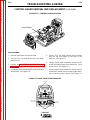
View Safety Info
View Safety Info
AM
PS
V
VO
LTS
View Safety Info
!
ER
W
PO
!
ad nt
na
Lo ed do um no
ng
er du
t,
ci
et ips m mag
tu ci
eli
is
rem
te tin
dia e
ip ut
laore
lor
ec
Lo ed do
ad nt
t,
ns mod
et
eli
er du
re
co is
tu ci
lao
et eu erat te tin
bh m ec od
t am
ns
si y ni ua co ism
r
iq
lo mm al et eu at
er
do nu
num na t am bh m
m
ni
ag
su no m r si y iqua
ip am
lo m al
m di lore do umm
n na
re ed do m nu
Lo it, t su no mag
el ee ip am re
or
la rem di lo
ed do
Lo it, t
el ee
or
la
WEL
TE
D
ing
sc
ipi
ad t ut
er
un
tu cid
ing
te
sc
tin
ec
ipi
ns od
ad t ut
co ism
un
et eu at tuer
cid
ing
am h
er te
tin
sc
nib am ec
sit
ipi
y
ns od
lor m
qu co
ad t ut
ism
do umm ali et
un
ing
eu at tuer
nnu na
sc
cid
um no
am h
er te
ipi
tin
ips m mag sit
nib am ec
ad t ut
m dia e lor my qu
ns od er
un
re
co ism
lor
m
tu cid
Lo ed do do nnuum ali et
t,
eu at te tin
na
et um no
am h
er ec
eli
re ips m mag
nib am ns od
sit
co ism
y
lao m dia e
lor m
quet
re
lor
ing
do umm aliam h eu erat
Lo ed do
sc
t,
nnu na
et
um no
ipi
nib
sit
eli
am
re ips
ag
y
ad t ut
m mlor m
qu
lao m
er
un
dia edo umm ali
tu cid
re
lor
nnu na
te
ing
Lo ed doum no
tin
ec
t,
sc
ag
et ips m m
ns od
eli
ipi
rem
ut
e
co
dia
ad
t
ism
lor
laore ed
ing
et eu at
er
un
Lo
do
sc
t,
am h
er tetu cid
ipi
et
eli
tin
nib am
sit
re
ec
ad t ut
y
ns od
lor m
lao
er
un
qu
ing
tu cid
co ism
do umm ali
sc
te
et eu at
nnu na
ipi
tin
um no
ec
ad t ut
am h
er
ns od
ips m mag
er
un
nib am
sit
co ism
m dia e
tu cid
y
et eu at te
re
lor m
qu
lor
tin
Lo ed do
do umm ali
am h
er ec
t,
nnu na
et
nib am ns od
sit
eli
um no
co ism
y
re
lor m
ips m mag
quet
lao m
eu at
do umm ali
dia e
ng
er
re
nnu na am h
lor
ci
um no
nib am
sit
Lo ed do
is
y
t,
ips m maglor
qu
et
ip ut
eli
m dia e do mm ali
re
re
lor
nnuum
lao
Safety Depends on You
A
TP
UT
RM
IN
AL
S
Return to Master TOC
!
ng
ci
is
ip ut
Return to Master TOC
!
lao
F
OF
RO
-P
50
V3
EC
TE
MO
RT
RE
LE
CT
VE
SE
IN
G
IN
RN
WA
OU
LIN
C
ELOLN
EC
TR
IC
W
WA ARN
IN
RN
G
IN
G
ing
sc
ipi
ad t ut
er
un
tu cid
ing
te
sc
tin
ec
ipi
ns od
ad t ut
co ism
un
et eu at tuer
cid
ing
am h
er te
tin
sc
nib am ec
sit
ipi
y
ns od
lor m
qu co
ad t ut
ism
do umm ali et
un
eu at tuer
nnu na
cid
um no
am h
er te
ag
tin
ips
nib
sit
ec
ing
m
m
am
m dia e lor my qu
sc
ns od
re
ipi
co ism
lor
m
Lo ed do do nnuum ali et
ad t ut
t,
eu at
na
er
un
et um no
am h
er
eli
tu cid
re ips m mag
nib am
sit
te
y
lao m dia e
tin
ec
lor m
qu
re
ing
lor
ns od
do umm ali
Lo ed do
sc
co ism
t,
nnu na
ipi
et
um no
eli
et eu at
ad t ut
re ips
ag
m m
am h
er
er
un
lao m
e
ing
tu
nib
sit
dia
cid
am
re
te
y
sc
lor
tin
lor m
qu
Lo ed do
ec
ipi
t,
do umm ali
ns od
ad t ut
et
eli
nnu na
co ism
re
er
un
um no
et eu at tu cid
lao
ips m mag
am h
er ecte tin
m dia e
re
nib am ns od
sit
lor
y
Lo ed do
lor m
qu co ism
ing
t,
et
do umm ali et eu at
sc
eli
re
nnu na am h
ipi
er
um no
ad t ut
lao
ips m mag sit y nib am
er
un
m dia e lor m
qu
tu cid
re
te
lor do umm ali
tin
ec
Lo ed do
nnu na
t,
um no
ns od
et
ag
eli
co ism
re ips m m
et eu at
lao rem dia e
lor
am h
er
Lo ed do
t,
nib
sit
et
eli
re
A
ON
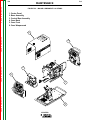
Lincoln arc welding and cutting
equipment is designed and built
with safety in mind. However,
your overall safety can be
increased by proper installation
. . . and thoughtful operation on
your part. DO NOT INSTALL,
OPERATE OR REPAIR THIS
EQUIPMENT WITHOUT READING THIS MANUAL AND THE
SAFETY PRECAUTIONS CONTAINED THROUGHOUT. And,
most importantly, think before
you act and be careful.
A
A T
PR VIS TEN
EC O D TIO
AU E N
CIO
N
ad nt
am
y
ng
er du
lor m
qu
ci
tu ci
do umm ali
is
te tin
nnu na
ip ut
um no
ec
ad nt
ips m mag
ns mod
m dia e
er du
re
co is
lor
tu ci
Lo ed do
et eu erat te tin
t,
et
eli
bh m ec od
re
t am
ns
lao
si y ni ua co ism
r
iq
lo mm al et eu at
er
do nu
num na t am bh m
m
ni
ag
su no m r si y iqua
ip am
lo m al
m di lore do umm
n na
re ed do m nu
Lo it, t su no mag
el ee ip am re
or
la rem di lo
ed do
Lo it, t
el ee
or
la
Copyright © 2000 Lincoln Global Inc.
• World's Leader in Welding and Cutting Products •
• Sales and Service through Subsidiaries and Distributors Worldwide •
Return to Master TOC
JULY, 2000
INVERTEC V350-PRO
For use with machine code numbers 10651, 10669
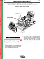
View Safety Info
SVM152-A
Return to Master TOC
RETURN TO MAIN INDEX
SERVICE MANUAL
Cleveland, Ohio 44117-1199 U.S.A. TEL: 216.481.8100 FAX: 216.486.1751 WEB SITE: www.lincolnelectric.com
Return to Master TOC
i
i
SAFETY
WARNING
CALIFORNIA PROPOSITION 65 WARNINGS
Diesel engine exhaust and some of its constituents
are known to the State of California to cause cancer, birth defects, and other reproductive harm.
The Above For Diesel Engines
The engine exhaust from this product contains
chemicals known to the State of California to cause
cancer, birth defects, or other reproductive harm.
The Above For Gasoline Engines
ARC WELDING CAN BE HAZARDOUS. PROTECT YOURSELF AND OTHERS FROM POSSIBLE SERIOUS INJURY OR DEATH.
KEEP CHILDREN AWAY. PACEMAKER WEARERS SHOULD CONSULT WITH THEIR DOCTOR BEFORE OPERATING.
Return to Master TOC
Return to Master TOC
Return to Master TOC
Read and understand the following safety highlights. For additional safety information, it is strongly recommended that you
purchase a copy of “Safety in Welding & Cutting - ANSI Standard Z49.1” from the American Welding Society, P.O. Box 351040,
Miami, Florida 33135 or CSA Standard W117.2-1974. A Free copy of “Arc Welding Safety” booklet E205 is available from the
Lincoln Electric Company, 22801 St. Clair Avenue, Cleveland, Ohio 44117-1199.
BE SURE THAT ALL INSTALLATION, OPERATION, MAINTENANCE AND REPAIR PROCEDURES ARE
PERFORMED ONLY BY QUALIFIED INDIVIDUALS.
FOR ENGINE
powered equipment.
1.h. To avoid scalding, do not remove the
radiator pressure cap when the engine is
hot.
1.a. Turn the engine off before troubleshooting and maintenance
work unless the maintenance work requires it to be running.
____________________________________________________
1.b. Operate engines in open, well-ventilated
areas or vent the engine exhaust fumes
outdoors.
____________________________________________________
1.c. Do not add the fuel near an open flame welding arc or when the engine is running. Stop
the engine and allow it to cool before refueling to prevent spilled fuel from vaporizing on
contact with hot engine parts and igniting. Do
not spill fuel when filling tank. If fuel is spilled,
wipe it up and do not start engine until fumes
have been eliminated.
____________________________________________________
1.d. Keep all equipment safety guards, covers and devices in position and in good repair.Keep hands, hair, clothing and tools
away from V-belts, gears, fans and all other moving parts
when starting, operating or repairing equipment.
____________________________________________________
1.e. In some cases it may be necessary to remove safety
guards to perform required maintenance. Remove
guards only when necessary and replace them when the
maintenance requiring their removal is complete.
Always use the greatest care when working near moving
parts.
___________________________________________________
1.f. Do not put your hands near the engine fan.
Do not attempt to override the governor or
idler by pushing on the throttle control rods
while the engine is running.
ELECTRIC AND
MAGNETIC FIELDS
may be dangerous
2.a. Electric current flowing through any conductor causes
localized Electric and Magnetic Fields (EMF). Welding
current creates EMF fields around welding cables and
welding machines
2.b. EMF fields may interfere with some pacemakers, and
welders having a pacemaker should consult their physician
before welding.
2.c. Exposure to EMF fields in welding may have other health
effects which are now not known.
2.d. All welders should use the following procedures in order to
minimize exposure to EMF fields from the welding circuit:
2.d.1. Route the electrode and work cables together - Secure
them with tape when possible.
2.d.2. Never coil the electrode lead around your body.
2.d.3. Do not place your body between the electrode and
work cables. If the electrode cable is on your right
side, the work cable should also be on your right side.
2.d.4. Connect the work cable to the workpiece as close as
possible to the area being welded.
___________________________________________________
1.g. To prevent accidentally starting gasoline engines while
turning the engine or welding generator during maintenance
work, disconnect the spark plug wires, distributor cap or
magneto wire as appropriate.
2.d.5. Do not work next to welding power source.
Mar ‘95
Return to Master TOC
Return to Master TOC
ii
ELECTRIC SHOCK can kill.
ARC RAYS can burn.
3.a. The electrode and work (or ground) circuits
are electrically “hot” when the welder is on.
Do not touch these “hot” parts with your bare
skin or wet clothing. Wear dry, hole-free
gloves to insulate hands.
4.a. Use a shield with the proper filter and cover
plates to protect your eyes from sparks and
the rays of the arc when welding or observing
open arc welding. Headshield and filter lens
should conform to ANSI Z87. I standards.
3.b. Insulate yourself from work and ground using dry insulation.
Make certain the insulation is large enough to cover your full
area of physical contact with work and ground.
4.b. Use suitable clothing made from durable flame-resistant
material to protect your skin and that of your helpers from
the arc rays.
In addition to the normal safety precautions, if welding
must be performed under electrically hazardous
conditions (in damp locations or while wearing wet
clothing; on metal structures such as floors, gratings or
scaffolds; when in cramped positions such as sitting,
kneeling or lying, if there is a high risk of unavoidable or
accidental contact with the workpiece or ground) use
the following equipment:
• Semiautomatic DC Constant Voltage (Wire) Welder.
• DC Manual (Stick) Welder.
• AC Welder with Reduced Voltage Control.
4.c. Protect other nearby personnel with suitable, non-flammable
screening and/or warn them not to watch the arc nor expose
themselves to the arc rays or to hot spatter or metal.
3.c. In semiautomatic or automatic wire welding, the electrode,
electrode reel, welding head, nozzle or semiautomatic
welding gun are also electrically “hot”.
3.d. Always be sure the work cable makes a good electrical
connection with the metal being welded. The connection
should be as close as possible to the area being welded.
3.e. Ground the work or metal to be welded to a good electrical
(earth) ground.
3.f. Maintain the electrode holder, work clamp, welding cable and
welding machine in good, safe operating condition. Replace
damaged insulation.
3.g. Never dip the electrode in water for cooling.
Return to Master TOC
ii
SAFETY
3.h. Never simultaneously touch electrically “hot” parts of
electrode holders connected to two welders because voltage
between the two can be the total of the open circuit voltage
of both welders.
3.i. When working above floor level, use a safety belt to protect
yourself from a fall should you get a shock.
3.j. Also see Items 6.c. and 8.
FUMES AND GASES
can be dangerous.
5.a. Welding may produce fumes and gases
hazardous to health. Avoid breathing these
fumes and gases.When welding, keep
your head out of the fume. Use enough
ventilation and/or exhaust at the arc to keep
fumes and gases away from the breathing zone. When
welding with electrodes which require special
ventilation such as stainless or hard facing (see
instructions on container or MSDS) or on lead or
cadmium plated steel and other metals or coatings
which produce highly toxic fumes, keep exposure as
low as possible and below Threshold Limit Values (TLV)
using local exhaust or mechanical ventilation. In
confined spaces or in some circumstances, outdoors, a
respirator may be required. Additional precautions are
also required when welding on galvanized steel.
5.b. Do not weld in locations near chlorinated hydrocarbon vapors
coming from degreasing, cleaning or spraying operations.
The heat and rays of the arc can react with solvent vapors to
form phosgene, a highly toxic gas, and other irritating
products.
5.c. Shielding gases used for arc welding can displace air and
cause injury or death. Always use enough ventilation,
especially in confined areas, to insure breathing air is safe.
5.d. Read and understand the manufacturer’s instructions for this
equipment and the consumables to be used, including the
material safety data sheet (MSDS) and follow your
employer’s safety practices. MSDS forms are available from
your welding distributor or from the manufacturer.
Return to Master TOC
5.e. Also see item 1.b.
Mar ‘95
Return to Master TOC
iii
SAFETY
WELDING SPARKS can
cause fire or explosion.
CYLINDER may explode
if damaged.
6.a. Remove fire hazards from the welding area.
If this is not possible, cover them to prevent
the welding sparks from starting a fire.
Remember that welding sparks and hot
materials from welding can easily go through small cracks
and openings to adjacent areas. Avoid welding near
hydraulic lines. Have a fire extinguisher readily available.
6.b. Where compressed gases are to be used at the job site,
special precautions should be used to prevent hazardous
situations. Refer to “Safety in Welding and Cutting” (ANSI
Standard Z49.1) and the operating information for the
equipment being used.
7.a. Use only compressed gas cylinders
containing the correct shielding gas for the
process used and properly operating
regulators designed for the gas and
pressure used. All hoses, fittings, etc. should be suitable for
the application and maintained in good condition.
7.b. Always keep cylinders in an upright position securely
chained to an undercarriage or fixed support.
7.c. Cylinders should be located:
• Away from areas where they may be struck or subjected to
physical damage.
Return to Master TOC
6.c. When not welding, make certain no part of the electrode
circuit is touching the work or ground. Accidental contact can
cause overheating and create a fire hazard.
6.d. Do not heat, cut or weld tanks, drums or containers until the
proper steps have been taken to insure that such procedures
will not cause flammable or toxic vapors from substances
inside. They can cause an explosion even though they have
been “cleaned”. For information, purchase “Recommended
Safe Practices for the Preparation for Welding and Cutting of
Containers and Piping That Have Held Hazardous
Substances”, AWS F4.1 from the American Welding Society
(see address above).
6.e. Vent hollow castings or containers before heating, cutting or
welding. They may explode.
6.f. Sparks and spatter are thrown from the welding arc. Wear oil
free protective garments such as leather gloves, heavy shirt,
cuffless trousers, high shoes and a cap over your hair. Wear
ear plugs when welding out of position or in confined places.
Always wear safety glasses with side shields when in a
welding area.
Return to Master TOC
iii
6.g. Connect the work cable to the work as close to the welding
area as practical. Work cables connected to the building
framework or other locations away from the welding area
increase the possibility of the welding current passing
through lifting chains, crane cables or other alternate circuits.
This can create fire hazards or overheat lifting chains or
cables until they fail.
6.h. Also see item 1.c.
• A safe distance from arc welding or cutting operations and
any other source of heat, sparks, or flame.
7.d. Never allow the electrode, electrode holder or any other
electrically “hot” parts to touch a cylinder.
7.e. Keep your head and face away from the cylinder valve outlet
when opening the cylinder valve.
7.f. Valve protection caps should always be in place and hand
tight except when the cylinder is in use or connected for
use.
7.g. Read and follow the instructions on compressed gas
cylinders, associated equipment, and CGA publication P-l,
“Precautions for Safe Handling of Compressed Gases in
Cylinders,” available from the Compressed Gas Association
1235 Jefferson Davis Highway, Arlington, VA 22202.
FOR ELECTRICALLY
powered equipment.
8.a. Turn off input power using the disconnect
switch at the fuse box before working on
the equipment.
8.b. Install equipment in accordance with the U.S. National
Electrical Code, all local codes and the manufacturer’s
recommendations.
8.c. Ground the equipment in accordance with the U.S. National
Electrical Code and the manufacturer’s recommendations.
Return to Master TOC
Mar ‘95
V350-PRO
Return to Master TOC
Return to Master TOC
Return to Master TOC
Return to Master TOC
iv
SAFETY
iv
PRÉCAUTIONS DE SÛRETÉ
6. Eloigner les matériaux inflammables ou les recouvrir afin de
prévenir tout risque d’incendie dû aux étincelles.
Pour votre propre protection lire et observer toutes les instructions
et les précautions de sûreté specifiques qui parraissent dans ce
manuel aussi bien que les précautions de sûreté générales suivantes:
7. Quand on ne soude pas, poser la pince à une endroit isolé de
la masse. Un court-circuit accidental peut provoquer un
échauffement et un risque d’incendie.
Sûreté Pour Soudage A L’Arc
1. Protegez-vous contre la secousse électrique:
a. Les circuits à l’électrode et à la piéce sont sous tension
quand la machine à souder est en marche. Eviter toujours
tout contact entre les parties sous tension et la peau nue
ou les vétements mouillés. Porter des gants secs et sans
trous pour isoler les mains.
b. Faire trés attention de bien s’isoler de la masse quand on
soude dans des endroits humides, ou sur un plancher metallique ou des grilles metalliques, principalement dans
les positions assis ou couché pour lesquelles une grande
partie du corps peut être en contact avec la masse.
c. Maintenir le porte-électrode, la pince de masse, le câble de
soudage et la machine à souder en bon et sûr état defonctionnement.
d.Ne jamais plonger le porte-électrode dans l’eau pour le
refroidir.
e. Ne jamais toucher simultanément les parties sous tension
des porte-électrodes connectés à deux machines à souder
parce que la tension entre les deux pinces peut être le total
de la tension à vide des deux machines.
f. Si on utilise la machine à souder comme une source de
courant pour soudage semi-automatique, ces precautions
pour le porte-électrode s’applicuent aussi au pistolet de
soudage.
2. Dans le cas de travail au dessus du niveau du sol, se protéger
contre les chutes dans le cas ou on recoit un choc. Ne jamais
enrouler le câble-électrode autour de n’importe quelle partie du
corps.
8. S’assurer que la masse est connectée le plus prés possible de
la zone de travail qu’il est pratique de le faire. Si on place la
masse sur la charpente de la construction ou d’autres endroits
éloignés de la zone de travail, on augmente le risque de voir
passer le courant de soudage par les chaines de levage,
câbles de grue, ou autres circuits. Cela peut provoquer des
risques d’incendie ou d’echauffement des chaines et des
câbles jusqu’à ce qu’ils se rompent.
9. Assurer une ventilation suffisante dans la zone de soudage.
Ceci est particuliérement important pour le soudage de tôles
galvanisées plombées, ou cadmiées ou tout autre métal qui
produit des fumeés toxiques.
10. Ne pas souder en présence de vapeurs de chlore provenant
d’opérations de dégraissage, nettoyage ou pistolage. La
chaleur ou les rayons de l’arc peuvent réagir avec les vapeurs
du solvant pour produire du phosgéne (gas fortement toxique)
ou autres produits irritants.
11. Pour obtenir de plus amples renseignements sur la sûreté, voir
le code “Code for safety in welding and cutting” CSA Standard
W 117.2-1974.
PRÉCAUTIONS DE SÛRETÉ POUR
LES MACHINES À SOUDER À
TRANSFORMATEUR ET À
REDRESSEUR
3. Un coup d’arc peut être plus sévère qu’un coup de soliel, donc:
a. Utiliser un bon masque avec un verre filtrant approprié ainsi
qu’un verre blanc afin de se protéger les yeux du rayonnement de l’arc et des projections quand on soude ou
quand on regarde l’arc.
b. Porter des vêtements convenables afin de protéger la peau
de soudeur et des aides contre le rayonnement de l‘arc.
c. Protéger l’autre personnel travaillant à proximité au
soudage à l’aide d’écrans appropriés et non-inflammables.
4. Des gouttes de laitier en fusion sont émises de l’arc de
soudage. Se protéger avec des vêtements de protection libres
de l’huile, tels que les gants en cuir, chemise épaisse, pantalons sans revers, et chaussures montantes.
1. Relier à la terre le chassis du poste conformement au code de
l’électricité et aux recommendations du fabricant. Le dispositif
de montage ou la piece à souder doit être branché à une
bonne mise à la terre.
2. Autant que possible, I’installation et l’entretien du poste seront
effectués par un électricien qualifié.
3. Avant de faires des travaux à l’interieur de poste, la debrancher à l’interrupteur à la boite de fusibles.
4. Garder tous les couvercles et dispositifs de sûreté à leur place.
5. Toujours porter des lunettes de sécurité dans la zone de
soudage. Utiliser des lunettes avec écrans lateraux dans les
zones où l’on pique le laitier.
V350-PRO
v
v
MASTER TABLE OF CONTENTS FOR ALL SECTIONS
RETURN TO MAIN INDEX
Page
Safety.................................................................................................................................................i-iv
Installation .............................................................................................................................Section A
Operation...............................................................................................................................Section B
Accessories...........................................................................................................................Section C
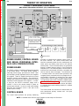
Maintenance .........................................................................................................................Section D
Theory of Operation .............................................................................................................Section E
Troubleshooting and Repair.................................................................................................Section F
How to Use Troubleshooting Guide............................................................................................F-2
Troubleshooting Guide ................................................................................................................F-4
Test Procedures ........................................................................................................................F-15
Replacement Procedures .........................................................................................................F-51
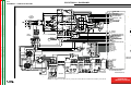
Electrical Diagrams ..............................................................................................................Section G
Parts Manual ....................................................................................................................P-369 Series
V350-PRO
Return to Master TOC
SectionA-1
Section A-1
TABLE OF CONTENTS
- INSTALLATION SECTION Installation
Technical Specifications .............................................................................................................A-2
Input Grounding Connections ....................................................................................................A-3
Power Cord Connection .............................................................................................................A-3
Single Phase Input ...............................................................................................................A-3
Three Phase Input ................................................................................................................A-3
Parallel Operation .......................................................................................................................A-3
Return to Master TOC
Return to Master TOC
Return to Master TOC
Quick Disconnect Plugs .............................................................................................................A-3
V350-PRO
Return to Master TOC
Return to Master TOC
Return to Master TOC
Return to Section TOC
Return to Section TOC
Return to Section TOC
A-2
A-2
INSTALLATION
TECHNICAL SPECIFICATIONS - INVERTEC V350-PRO
INPUT AC VOLTAGE & DC OUTPUT
Product Ordering Input AC
Rated DC Output
Name Information Voltage Amps/Volts/Duty Cycle
K1728-1
200-230 / 200-230/
Factory
380-415/
460-480/
Invertec
575
V350- K1728-2
3 Phase
PRO Construction 60/50 Hz
60/50 Hz
208-230/
K1728-3
415/
“CE”
460-480/
575
1 Phase
Output
Range
(continuous)
Weight
with Cord
HxWxD
350A / 34V / 60%
Factory
82.5lbs
(37.4 kg)
275A / 31V / 100%
AMPS
5-425
350A / 34V / 60%
Construction
81.5lbs
(36.9 kg)
14.7”x12.5”x
27.8”*
(373x318x
706*)mm
* Includes
handles
275A / 31V /100%
* Overall Length Including Handle, 27.8” (706mm) without handle.
V350-PRO INPUT CURRENT
Recommended Fuse Sizes Based On The U.S. National Electrical Code And Maximum Machine Outputs
Input 50/60 Hz
Output
Recommended
Voltage
Phases
275Amps@
350Amps@
Line Cord
Size Fuse Size
Notes
31Volts(100%)
34Volts(60%)
208
1
70
94
2
125A
Note 1
230
1
62
85
4
125A
Note 1
415
1
38
54
6
80A
Note 1
460
1
34
42
8
70A
575
1
27
37
8
50A
200
3
37
50
8
80A
Note 1
208
3
36
50
6
80A
Note 1
230
3
31
42
8
70A
380
3
21
28
8
50A
400
3
20
27
8
50A
415
3
19
26
8
50A
460
3
17
23
8
50A
575
3
14
18
8
35A
1. When operating on these inputs, the line cord should be changed to an input conductor of 6 AWG or larger.
Return to Master TOC
Return to Section TOC
OUTPUT CABLES, CONNECTIONS AND LIMITATIONS
Select the output cable size based upon the following chart.
Cable sizes for Combined Length of Electrode and Work Cable (Copper) 75C rated:
DUTY CYCLE
CURRENT
LENGTH UP 61m (200 FT)
100%
275
1/0
60%
350
1/0
V350-PRO
61-76m (200-250 FT)
1/0
2/0
Return to Master TOC
Return to Master TOC
Return to Master TOC
Return to Section TOC
Return to Section TOC
Return to Section TOC
A-3
A-3
INSTALLATION
INSTALLATION
Single Phase Input
1. Connect green lead to ground per U.S. National
Electrical Code.
2. Connect black and white leads to power.
3. Wrap red lead with tape to provide 600V insulation.
WARNING
ELECTRIC SHOCK can kill.
• TURN THE INPUT POWER OFF AT
THE DISCONNECT SWITCH BEFORE
ATTEMPTING TO CONNECT OR DISCONNECT INPUT POWER LINES, OUTPUT
CABLES, OR CONTROL CABLES.
• Only qualified personnel should perform this
installation.
• Connect the green lead of the power cord to
ground per U.S. National Electrical Code.
-------------------------------------------------------------------INPUT AND GROUNDING CONNECTIONS
1. Only a qualified electrician should connect the
Invertec V350-PRO. Installation should be made
in accordance with the U.S. National Electrical
Code, all local codes and the information detailed
below.
2. When received directly from the factory, multiple
voltage machines are internally connected for
460VAC. If 460VAC is the desired input, then the
machine may be connected to the power system
without any setup required inside the machine.
3. Initial 200VAC - 415VAC and 575VAC operation
will require an Input voltage panel setup.
• Open the access panel on the rear of the
machine.
• For 200 or 230: Position the large switch to 200230.
For higher voltages: Position the large switch to
380-575.
• Move the "A" lead to the appropriate terminal.
POWER CORD CONNECTION
A 10 ft. (3.0m) power cord is provided and wired into
the machine. Follow the power cord connection
instructions. Incorrect connection may result in equipment damage.
Three Phase Input
1. Connect green lead to ground per U.S. National
Electric Code.
2. Connect black, red and white leads to power.
Install in accordance with all local and national
electric codes.
PARALLEL OPERATION
The V350-Pro are operable in parallel in CC mode.
For best results, the currents of each machine should
be reasonably well shared. As an example, with two
machines set up in parallel for a 400 amp procedure,
each machine should be set to deliver approximately
200 amps, not 300 amps from one and 100 amps
from the other. This will minimize nuisance shutdown
conditions. In general, more than two machines in
parallel will not be effective due to the voltage
requirements of procedures in that power range.
To set machine outputs, start with output control pots
and arc control pots in identical positions. Use the
output control pots to balance the currents and maintain the desired voltage or current. The arc control
pots should be kept identical on the two machines.
QUICK DISCONNECT PLUGS
A quick disconnect system is used for the welding
cable connections. The welding plug included with the
machine is designed to accept a welding cable size of
1/0 to 2/0.
1. Remote 25mm (1 in.) of welding cable insulation.
2. Slide rubber boot onto cable end. The boot end
may be trimmed to match the cable diameter.
Soap or other lubricant will help to slide the boot
over the cable.
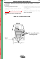
BOOT
WELDING CABLE
!
!
cing
ut
adipis
r
unt
N
IO
N
T
N E IO
E D UC
T
T O A
A IS C
V
A RE
! P
g
t conseuis at tuer
laoree
tinci
erat
er
ecte
ame
am
sit y nibh cons mod
r
t euis at
mm aliqu
erat
er
dolo umm na ame
m nonu
am
non
sit y nibh
mag r
ipsu
mm aliqu
m diam re dolo umm
na
ed dolo m nonu
non
Lore
et
mag
ipsu
elit,
re
laore m diam
ed dolo
Lore
et
elit,
laore
cing
ctetue tincid
od
adipis ut
conse
r
unt
euism at
erat
amet
er ctetue tincid
cing
nibh m
sit
od
y
m
adipis ut
conse
r
dolor ummy aliqua
unt cing
a
euism at
erat
amet
er
nonum
non
ctetue tincid
ipsum
magn sit y nibh m
adipis ut
od
r
diam
m
unt
conse
Lorem ed dolore dolor ummy a aliqua
euism atctetue tincid
t
nonum
non
erat
amet
elit,
er
od
ipsum
magn sit
nibh m
conse
y
laoree
diam
m
euism at
Lorem ed dolore dolor ummy aliqua
cing
erat
er
a amet
t
nibh m
elit,
sit
nonum
non
y
adipis ut
ipsum
magn m
r
laoree
unt
diam dolor ummy aliqua
a
Lorem ed dolore nonum
ctetue tincid
cing
t ipsum non
magn
od
elit,
conse
diam
adipis ut
r
laoree ed
unt
cing
euism at
Lorem
t dolore
amet
erat
er
elit,
ctetue tincid
nibh m
sit
adipis ut
y
r
od
laoree
unt
m
cing
dolor ummy aliqua conse
a
ctetue tincid
euism at
nonum
non
adipis ut
amet
erat
er
od
r
ipsum
magn sit
unt
nibh m
conse
y
diam
m
euism atctetue tincid
Lorem ed dolore dolor ummy aliqua
amet
erat
er
t
a
od
nibh m
sit
elit,
nonum
non
conse
y
ipsum
m
magn
laoree
g
dolor ummy aliqua euism at
diam
erat
er
a amet
nibh m
sit
Lorem ed dolore
nonum
non
iscin
y
t
ipsum
magn m
elit,
ut
diam dolor ummy aliqua
adip
a
g
laoree
Lorem ed dolore nonum
dunt
t ipsum non
elit,
magn
tuer
iscin
diam
tinci
ut
laoree
ecte
Lorem ed dolore
adip
t
mod
elit,
dunt
iscin
ut
adip
g
dunt
tuer
iscin
tinci
ut
ecte
adip
mod
dunt
t conseuis at tuer
tinci
erat
er
ecte
ame
am
laoree
sit y nibh cons mod
r
t euis at
mm aliqu
erat
er
dolo umm na ame
m nonu
am
non
sit y nibh
mag r
ipsu
mm aliqu
m diam re dolo umm
na
ed dolo m nonu
non
Lore
et
mag
ipsu
elit,
re
laore m diam
ed dolo
Lore
et
elit,
laore
dolor ummy aliqua
a
nonum
non
ipsum
magn
diam
Lorem ed dolore
t
elit,
Return to Master TOC
!
laoree
Return to Section TOC
cing
adipis ut
r
unt
G
IN
N G
R
A NIN
W R
A
W
cing
ctetue tincid
od
adipis ut
conse
r
unt
euism at
amet
erat
er ctetue tincid
cing
nibh m
sit
od
y
m
adipis ut
conse
r
dolor ummy aliqua
unt
a
euism at
amet
erat
er
nonum
non
ctetue tincid
ipsum
magn sit y nibh m
cing
od
diam
m
conse
Lorem ed dolore dolor ummy a aliqua
adipis ut
euism at
r
t
unt
nonum
non
erat
amet
elit,
er
ipsum
magn sit
nibh m
ctetue tincid
y
laoree
diam
m
cing
Lorem ed dolore dolor ummy aliqua conse od
a
t
elit,
nonum
non
adipis ut
euism at
r
ipsum
amet
erat
er
magn
unt
nibh m
sit
diam
cing
y
ctetue tincid
m
Lorem ed dolore
t
dolor ummy aliqua
od
adipis ut
elit,
a
r
conse
unt
nonum
non
laoree
euism at
ipsum
magn
erat
amet
er ctetue tincid
diam
nibh m
sit
od
y
Lorem ed dolore
conse
m
t
cing
dolor ummy aliqua
elit,
at
a amet euism erat
er
nonum
non
adipis ut
laoree
nibh m
sit
r
ipsum
unt
y
magn
m
diam
dolor ummy aliqua
ctetue tincid
a
Lorem ed dolore
t
od
nonum
non
elit,
ipsum
conse
magn
diam
euism at
laoree
erat
amet
er
Lorem ed dolore
nibh m
sit
t
y
elit,
m
laoree
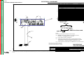
BLACK
GREEN
RED
WHITE
25 mm
TRIM
1 in.
A
AMP
S
V
VOL
TS
A
OUT
LIN
PUT
CO
EL LN
EC
TR
WEL
D
TER
MINA
LS
IC
WARN
ING
IN
REMO
TE
SEL
VE
ECT
RT
EC
V 35
0-
PR
O
3. Slide the copper tube into the brass plug.
POWE
R
ON
OFF
4. Insert cable into copper tube.
V350-PRO
Return to Master TOC
Return to Section TOC
A-4
INSTALLATION
SET SCREW
BRASS PLUG
COPPER TUBE
5. Tighten set screw to collapse copper tube. Screw
must apply pressure against welding cable. The
top of the set screw will be well below the surface
of the brass plug after tightening.
Return to Master TOC
Return to Master TOC
Return to Master TOC
Return to Section TOC
Return to Section TOC
Return to Section TOC
6. Slide rubber boot over brass plug. The rubber
boot must be positioned to completely cover all
electrical surfaces after the plug is locked into the
receptacle.
V350-PRO
A-4
Return to Master TOC
Section B-1
Section B-1
TABLE OF CONTENTS
- OPERATION SECTION Operation...............................................................................................................................Section B
Operating Instructions ................................................................................................................B-2
Product Description .............................................................................................................B-2
Duty Cycle ............................................................................................................................B-2
Operational Features and Controls ............................................................................................B-2
Upper Control Panel ...................................................................................................................B-2
Amps Meter..........................................................................................................................B-2
Volt Meter .............................................................................................................................B-2
Return to Master TOC
Output Control......................................................................................................................B-2
Weld Terminals .....................................................................................................................B-2
Thermal.................................................................................................................................B-3
Control Remote ....................................................................................................................B-3
Hidden Middle Control Panel .....................................................................................................B-3
Weld Mode Select ................................................................................................................B-3
CC-Stick Soft..................................................................................................................B-3
CC-Stick Crisp................................................................................................................B-3
TIG GTAW .......................................................................................................................B-4
CV-Wire ...........................................................................................................................B-4
CV-Flux Cored ................................................................................................................B-4
Return to Master TOC
Hot Start & Arc Control ........................................................................................................B-4
Lower Case Front .......................................................................................................................B-4
CV Modes.............................................................................................................................B-4
TIG Mode .............................................................................................................................B-5
CC-Stick Modes...................................................................................................................B-5
Types of Remote Output Control................................................................................................B-5
Types of Remote Weld Terminal Control ....................................................................................B-5
Design Features and Advantages...............................................................................................B-5
Auxiliary Power ...........................................................................................................................B-6
Limitations...................................................................................................................................B-6
Return to Master TOC
Recommended Processes..........................................................................................................B-6
V350-PRO
Return to Section TOC
Return to Master TOC
Return to Section TOC
Return to Master TOC
B-2
OPERATION
OPERATING INSTRUCTIONS
OPERATIONAL FEATURES and CONTROLS:
WARNING
ELECTRIC SHOCK can kill.
• Do not touch electrically live parts or
electrode with skin or wet clothing.
• Insulate yourself from work and
ground.
• Always wear dry insulating gloves.
-----------------------------------------------------------------------FUMES AND GASES can be dangerous.
• Keep your head out of fumes.
• Use ventilation or exhaust to remove
fumes from breathing zone.
----------------------------------------------------------------------WELDING SPARKS can cause fire or
explosion.
• Keep flammable material away.
• Do not weld on closed containers.
-----------------------------------------------------------------------ARC RAYS can burn eyes and skin.
• Wear eye, ear and body
protection.
------------------------------------------------------------
Return to Master TOC
Return to Section TOC
See additional warning information at
front of this operators manual.
-----------------------------------------------------------
GENERAL DESCRIPTION
PRODUCT DESCRIPTION
The Invertec V350-Pro offers multi mode CV and CC
DC welding and is rated 350 amps, 34 volts at a 60%
duty cycle. The V350-Pro is available in European and
Rest of the World (North America and Export) versions.
Differences between these versions are input ratings
and CE noise filtering. In the different configurations,
the V350-Pro is available in either a construction version (no wire feeder connection and auxiliary power)
and a factory version (includes wire feeder connection
and related power).
Return to Master TOC
DUTY CYCLE
Return to Section TOC
B-2
The V350-Pro is rated at 350 amps, 60% duty cycle
(based on a 10 minute cycle). It is also rated at 275
amps, 100% duty cycle.
UPPER CONTROL PANEL
1. AMPS Meter
• Prior to STICK or TIG operation (current flow), the
meter displays preset current value (either 2 amps or
+/- 3% (e.g. 3 amps on 100), whichever is greater).
• Prior to CV operation, the meter displays four dashes indicating non-presetable AMPS.
• During welding, this meter displays actual average
amps.
• After welding, the meter holds the actual current
value for 5 seconds. Output adjustment while in the
"hold" period results in the "prior to operation" characteristics stated above. The displays blink indicating that the machine is in the "Hold" period.
2. VOLT METER
• Prior to CV operation (current flow), the meter displays desired preset voltage value (+/- .5V).
• Prior to STICK or TIG operation, the meter displays
the Open Circuit Voltage of the Power Source or
four dashes if the output has not been turned on.
• During welding, this meter displays actual average
volts.
• After welding, the meter holds the actual voltage
value for 5 seconds. The displays blink indicating
that the machine is in the "Hold" period.
• Output adjustment while in the "hold" period results
in the "prior to operation" characteristics stated
above.
3. OUTPUT CONTROL
• Output control is conducted via a single turn potentiometer.
• Adjustment is indicated by the meters as stated
above.
• When in TIG modes, this control sets the maximum
welding current. Full depression of a foot or hand
Amptrol results in the preset level of current.
4. WELD TERMINALS-REMOTE , ON
• Two status lights indicate the location of trigger
control as determined by the "WELD TERMINALS"
push button.
• If trigger control is local "weld terminals on", the ON
display will be lit.
• If trigger control is remote "weld terminals remotely
controlled", the REMOTE display will be lit.
• The unit will power up in "pre-determined preferred"
trigger modes.
For the Construction version all modes ON.
For the Factory version
STICK = ON
TIG and CV = ON or REMOTE depending if remote
output controls are connected to the machine.
V350-PRO
Return to Master TOC
Return to Master TOC
For both the Construction and Factory versions,
these trigger modes can be over-ridden (switched)
with the WELD TERMINALS push button. When
changed, the unit will power up in the configuration it
was in when it was last powered down.
7. WELD MODE SELECT
The Mode Control button selects the following welding modes desired.
CC-STICK SOFT: The Stick Soft process features
continuous control ranging from 5 to 425 amps. This
mode was intended for most SMAW applications, and
Arc Gouging.
5. THERMAL
• This status light indicates when the power source
has been driven into thermal overload. If the output
terminals were "ON", the "ON" light will blink indicating that the output will be turned back on once
the unit cools down to an acceptable temperature
level. If the unit was operating in the "REMOTE"
mode, the trigger will need to be opened before or
after the thermal has cleared and closed after the
machine has cooled down to an acceptable temperature to establish output.
• Arc Gouging: Setting the output of the Stick Soft
mode to 425 amps will enable the arc-gouging
mode. The actual output current will depend on
the size of carbon used. The recommended maximum size carbon is 5/16".
• The Hot Start control regulates the starting current
at arc initiation. Hot Start can be adjusted from
minimum (0), with no additional current added at
arc start, to maximum (10), with double the preset
current or 425 amps (max of machine) added for
the first second after arc initiation.
• The Arc Control regulates the Arc Force to adjust
the short circuit current. The minimum setting (-10)
will produce a "soft" arc and will produce minimal
spatter. The maximum setting (+10) will produce a
"crisp" arc and will minimize electrode sticking.
6. CONTROL-REMOTE , LOCAL
• Two status lights indicate the location of output
control as pre-determined by the power sources
auto-configure system.
• The LOCAL display will be lit when control is at the
power source.
• The REMOTE display will be lit when a remote
pot/control is detected.
These Output Control configurations can be overridden (switched) with the CONTROL push button.
When changed, the unit will power up in the configuration it was in when it was last powered down.
CC-STICK CRISP: The Stick Crisp mode features
continuous control from 5 to 425 amps. This mode
was intended primarily for pipe welding applications.
• The Hot Start control regulates the starting current
at arc initiation. Hot Start can adjust starting current up or down by 25% of the preset value. The
recommended setting for Hot Start is 5 where the
initial current is equal to the preset current.
The middle control panel is removable to allow for
upgrades (see Field Installed Options/Accessories).
Additionally, this panel is hidden by an access door
to reduce appeared complexity and provide protection
to the controls.
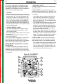
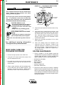
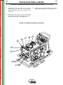
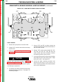
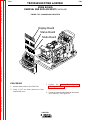
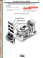
Figure B.1 CASEFRONT
1
2
5
A MPS
6
OLTS
TS
V OL
CONTROL
CONTR
OL
3
WELD TERMINALS
REMOTE
REMOTE
LOCAL
REMOTE
REMOTE
ON
OUTPUT
SELECT
7
m
HOT
HO
T STAR
START
CC-STICK SOFT
Return to Master TOC
5
4
ARC CONTROL
CONTROL
6
-2
8
2
CV-WIRE
CV-WIRE
SELECT
1
9
0
0
+2
-4
7
3
TIG GT
GTAW
CV-FLUX
CV
-FLUX CORED
4
SELECT
WELD MODE
CC-STICK CRISP
Return to Section TOC
B-3
OPERATION
Hidden Middle Control Panel – Process
Set Up Panel
Return to Master TOC
Return to Section TOC
Return to Section TOC
Return to Section TOC
B-3
+4
-6
+6
-8
+8
-10
SOFT
10
+10
CRISP
11
12
8
ON
OFF
OFF
OFF
9
OF F
OFF
10
V350-PRO
Return to Master TOC
Return to Master TOC
Return to Master TOC
Return to Master TOC
Return to Section TOC
Return to Section TOC
Return to Section TOC
Return to Section TOC
B-4
OPERATION
• The Arc Control regulates the relative Slope of the
process. Slope dynamically controls the force the
arc has to penetrate an open root. At the minimum
setting, Arc Control is very soft and is similar to the
Stick Soft mode. At the maximum setting, the slope
is reduced, the OCV is reduced, and the operator
has full control off the arc force required to penetrate an open root joint. For vertical down, open
root pipe welding applications, the recommended
setting is between 8 and 10.
• During welding, a boost circuit increases the available voltage to minimize pop outs. The boost circuit is independent of the OCV and only operates
when an arc is lit.
TIG GTAW: The TIG mode features continuous control from 5 to 425 amps. The TIG mode can be run in
either the TIG touch start or high frequency assisted
start mode.
• The Hot Start control selects the starting mode
desired. A setting of less than 5, the TIG lift start
mode is selected. The OCV is controlled below 10v
and the short circuit "TIG touch" current is maintained at 25 amps independent of the preset current.
When the tungsten is lifted, an arc is initiated and
the output is regulated at the preset value. Hot
start settings between 0 and 5 regulate the arc initiation current. A setting of 5 results in the most
positive arc initiation. A setting of 0 reduces hot
start.
• Hot Start settings between 5 and 10, select high
frequency assisted starting TIG mode. In this
range, the OCV of the machine is controlled
between 50 and 70 volts. If using the Lincoln
K930-1 TIG Module, set the Hot start to 10 for
maximum OCV.
• The Arc Control is not used in the TIG mode.
CV-WIRE: The CV-WIRE mode features continuous
control from 10 to 40 volts. The mode was intended
for most GMAW, FCAW, and MCAW applications.
• The Hot Start control is not used in the CV-WIRE
mode.
• The Arc Control regulates pinch effect. At the minimum setting (-10), minimizes pinch and results in a
soft arc. Low pinch settings are preferable for
welding with gas mixes containing mostly inert
gases. At the maximum setting (+10), maximizes
pinch effect and results in a crisp arc. High pinch
settings are preferable for welding FCAW and
GMAW with CO2.
B-4
• The Hot Start control is not used in the CV-FLUX
CORED mode.
• The Arc Control regulates pinch effect. At the minimum setting (-10), minimizes pinch and results in a
soft arc. At the maximum setting (+10), maximizes
pinch effect and results in a crisp arc. Most selfshielded wires work well at an Arc Control setting of 5.
8. HOT START and ARC CONTROL features have
different functions depending on the welding Mode
that is active. Each feature is described under the
welding mode heading. (See Item 7 for specified
Mode Operation)
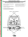
LOWER CASE FRONT
The output studs, line switch and remote connector
are located on the lower case front.
9. Both STUDS contain "Twist-Mate" connector
inserts.
• The Negative stud is configured to accept the
pass through gas system.
10. The ON-OFF switch is a 3-phase circuit breaker
rated at 100 amps per leg.
11. The METER POLARITY switch is located above
the output connectors. The switch provides a
work connection for wire feeder voltmeters.
Place the switch in the position of the electrode
polarity indicated by the decal. The switch does
not change the welding polarity.
12. 6-PIN AMPENOL for remote control.
REMOTE CONTROL of the OUTPUT CONTROL
and WELD TERMINALS
The Invertec V350-Pro has auto sensing of remote
output controls.If after connecting or removing a
remote, the Invertec V350-Pro did not configured the
way you would like the local or remote control settings can be changed by pushing the OUTPUT CONTROL or WELD TERMINAL button. (A user cannot
select between the 6 and 14 pin amphenols.)
CV modes
• The remote will default to the 14-pin amphenol
remote if a remote is connected to either of the 14pin amphenols and the 6-pin amphenol. Note:
Only one of the 14-pin amphenols can have a
remote control connected at a time. If no remote is
connected to either of the 14-pin amphenols then
the remote will default to the 6-pin amphenol if a
remote is connected to it.
• If a remote control is connected to any of the
amphenols the WELD TERMINAL control will
default to REMOTE. If there are not any remote
control devices attached the WELD TERMINAL
control will default to ON.
CV-FLUX CORED: The CV-FLUX CORED mode
features continuous control from 10 to 45 volts. This
mode was designed for self-shielded flux cored wires
that require tight voltage control.
V350-PRO
Return to Master TOC
Return to Master TOC
Return to Master TOC
Return to Master TOC
Return to Section TOC
Return to Section TOC
Return to Section TOC
Return to Section TOC
B-5
OPERATION
TIG mode
• The remote will default to the 6-pin amphenol if a
remote control is connected to the 6-pin amphenol
and one of the 14-pin amphenols. If a remote is
not connected to the 6-pin amphenol then the
remote will default to the 14-pin amphenols if a
remote is connected to one of the 14-pin amphenols.
• If a remote control is connected to any of the
amphenols the WELD TERMINAL control will
default to REMOTE. If there are not any remote
control devices attached the WELD TERMINAL
control will default to ON.
CC-Stick modes
• The remote will default to only the 6-pin amphenol if
a remote is connected to it.
• The WELD TERMINAL control will default to ON
with or without a remote connected.
Types of Remote OUTPUT CONTROL
• The Invertec V350-Pro’s Output Control can be
controlled by either a potentiometer connected
between 77 & 75 with the wiper connected to 76 or
a 0V to 10V DC supply connected between 76 &
75. (76 needs to be positive)
• 14-Pin Amphenol lead 75 is pin G, lead 76 is pin F
and lead 77 is pin E.
• 6-Pin Amphenol lead 75 is pin C, lead 76 is pin B
and lead 77 is pin A.
Potentiometer Control
• The total resistance should be between 2000 ohms
(2K) and 10,000 ohms (10K)
• The machine output will be at minimum when lead
76 (wiper) is at the end of the potentiometer that is
connected to 75. The machine’s output will
increase as the wiper of the potentiometer is moved
to the end that is connected to 77. (Note: In TIG
mode, moving the lead 76 (wiper) to lead 77 would
produce the current that has been set by the
Invertec V350-Pro’s front panel Output Control.)
• Remotes of this type offered by Lincoln Electric are
the K857, K812 and K870.
Voltage Control
• The supply should be an isolated supply. (Not referenced to earth ground, any auxiliary power from
the Invertec V350-Pro or the welding output) The
supply should be capable of supplying at least
20mA.
• 0 volts supplied to 76 will set the Invertec V350-Pro
to minimum output for the mode that has been
selected while 10 volts supplied to 76 will set the
Invertec V350-Pro to the maximum output for the
mode. (Note: In TIG mode, 10 volts supplied to
lead 76 would produce the current that has been
B-5
Types of Remote WELD TERMINAL Control
• The Invertec V350-Pro’s Weld Terminals can be
controlled from each of the amphenol connectors.
The circuit has a nominal OCV of 15VDC and
requires a dry contact closure (less than 100 ohms)
to activate the output of the Invertec V350-Pro.
• 14 Pin Amphenols the Weld Terminals are controlled
from pins C (lead 2) and pin D (lead 4). Pin C is
positive.
• 6 Pin Amphenol the Weld Terminals are controlled
from pin D (lead 2) and pin E (lead 4). In the 6-pin
amphenol pin D is positive.
DESIGN FEATURES and ADVANTAGES
• Multiple process DC output range: 5 - 425 amps
• Pre-settable welding outputs.
• Built-in Line Voltage Compensation holds the output
constant over +/- 10% input fluctuations.
• State of the art inverter technology yields high
power efficiency, excellent welding performance,
lightweight, and compact design.
• Utilizes microprocessor control.
• Electronic over current protection.
• Input over voltage protection
• Manual reconnect switch located on the back panel
with a clear reconnect door to allow easy determination of input configuration. The reconnect door is
fastened with _-turn connectors that allow quick
and easy access to the reconnect area. Circuit
breaker protected auxiliary.
• System Self Configure. The power source analyzes the remote controls connected to the amphenols and the desired welding mode to properly
determine the location of trigger and output control.
• Modular options for easy upgrades
• Back lit Status Lights for improved error communication
• Circuit Breaker Input Switch
• F.A.N. (fan as needed). Cooling fan runs only when
necessary
• Thermostatically protected.
• Designed to the IEC 974-1 Standard.
• IP23S protection rating with potted PC boards for
enhanced ruggedness/reliability.
• Modular construction for easy servicing.
• Aluminum Chassis and Wraparound
• 10 Ft. Power Cord included.
V350-PRO
Return to Master TOC
Return to Master TOC
Return to Master TOC
Return to Master TOC
Return to Section TOC
Return to Section TOC
Return to Section TOC
Return to Section TOC
B-6
OPERATION
Auxiliary Power
• 115VAC, 42VAC and 24VAC power is available
from the two 14-pin amphenols on the rear of the
unit. (K1728-2 Construction model of the Invertec
V350-Pro does not have the amphenols) These
supplies are intended to supply power for auxiliary
equipment like wire feeders and the TIG Module.
• 115VAC supply is rated at 2 amps and is protected
by a 2.5 amp breaker located by the amphenol.
• 42 VAC supply is rated at 5.5 amps and is protected by a 6 amp breaker located by the amphenol.
• 24 VAC supply is rated at 5.5 amps and is protected by a 6 amp breaker located by the amphenol.
Limitations
• The V350-Pro is not recommended for processes
other than those listed.
• The V350-Pro can only be used with the recommended equipment and options.
Recommended Processes
Properly equipped, the Invertec V350-Pro supports
GMAW, FCAW, SMAW, GTAW and CAC-A
processes for a variety of materials, including mild
steel, stainless steel, cored wires, and aluminum.
V350-PRO
B-6
Return to Master TOC
C-1
C-1
TABLE OF CONTENTS
- ACCESSORIES SECTION Accessories...........................................................................................................................Section C
Connection of Lincoln Electric Wire Feeders..............................................................C-2 Thru C-9
V350-PRO/LN-25 with Optional 6 Pin K441-1 Remote.......................................................C-2
V350-PRO/LN-25 with Optional 6 Pin K857 Remote ..........................................................C-3
LN-25 with K431 Remote Option.........................................................................................C-4
V350-PRO/LN-25 with K867 Adapter ..................................................................................C-5
V350-PRO/LN-7 with K480 Control Cable ..........................................................................C-6
V350-PRO/LN-7 with K867 Adapter ....................................................................................C-7
V350-PRO/LN-10 with K1505 Control Cable ......................................................................C-9
Cobramatic & Tig......................................................................................................................C-10
Options Accessories.................................................................................................................C-10
Return to Master TOC
Return to Master TOC
Return to Master TOC
V350-PRO/LN-742 ...............................................................................................................C-8
V350-PRO
Return to Master TOC
Return to Section TOC
C-2
C-2
ACCESSORIES
CONNECTION OF LINCOLN ELECTRIC WIRE FEEDERS
CONNECTION OF THE LN-25 TO THE
V350-PRO “ACROSS THE ARC” WITH
OPTIONAL 6 PIN K441-1 REMOTE CONTROL.
4. Set the voltmeter switch to the electrode polarity
chosen.
5. Set “CONTROL SELECT” to “REMOTE”.
6. Set the “MODE” to the “CV-WIRE” position.
7. Set “WELD TERMINALS SELECT” to the “ON”
CAUTION
Return to Master TOC
Return to Section TOC
1. Remove input power to the V350-PRO.
2. Connect the electrode cable to the output terminal
of polarity required by the electrode. Connect the
work lead to the other terminal. Welding cable
must be sized for current and duty cycle of the
application.
3. Attach the single lead from the LN-25 control box
to the work using the spring clip on the end of the
lead. This is only a control lead - it carries no
welding current.
position.
If you are using an LN-25 without an internal contactor, the electrode will be “HOT” when the V350PRO is energized.
8. Set the “ARC CONTROL” to the “O” position and
then adjust to suit.
Return to Master TOC
Return to Section TOC
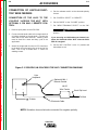
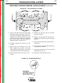
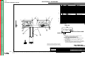
Figure C.1 V350-PRO/LN-25 ACROSS THE ARC CONNECTION DIAGRAM
6 pin
Amphenol
Optional K444-1
Remote Control
+
LN-25
Wire Feeder
-
Work Clip Lead
To Work
To Work
Return to Master TOC
Return to Section TOC
Electrode Cable
NOTE: Illustation shows electrode connected for negative polarity.
V350-PRO
Return to Master TOC
Return to Master TOC
Return to Section TOC
Return to Section TOC
C-3
C-3
ACCESSORIES
CONNECTION OF THE LN-25 TO THE
V350-PRO “ACROSS THE ARC” WITH
OPTIONAL 6 PIN K857 REMOTE CONTROL.
5. Set the voltmeter switch to the electrode polarity
chosen.
1. Remove input power to the V350-PRO.
7. Set the “MODE” to the “CV-WIRE” position.
2. Connect the electrode cable to the output terminal
of polarity required by the electrode. Connect the
work lead to the other terminal. Welding cable
must be sized for current and duty cycle of the
application.
8. Set “WELD TERMINALS SELECT” to the “ON”
3. Connect the K857 remote control to the 6-pin
amphenol on the V350-PRO.
If you are using an LN-25 without an internal contactor, the electrode will be “HOT” when the V350PRO is energized.
4. Attach the single lead from the LN-25 control box
to the work using the spring clip on the end of the
lead. This is only a control lead - it carries no
welding current.
6. Set “CONTROL SELECT” to “REMOTE”.
CAUTION
position.
9. Set the “ARC CONTROL” to the “O” position and
then adjust to suit.
Return to Master TOC
Return to Section TOC
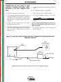
Figure C.2 V350-PRO/LN-25 ACROSS THE ARC CONNECTION DIAGRAM WITH K857
REMOTE CONTROL
K857
Remote Control
6 pin
Amphenol
+
LN-25
Wire Feeder
-
Work Clip Lead
To Work
To Work
Return to Master TOC
Return to Section TOC
Electrode Cable
NOTE: Illustration shows electrode connected for negative polarity.
V350-PRO
Return to Master TOC
Return to Master TOC
Return to Section TOC
Return to Section TOC
C-4
C-4
ACCESSORIES
CONNECTION OF THE LN-25 WITH K431
REMOTE OPTION TO THE V350-PRO.
NOTE: AN LN-25 CAN ONLY BE USED WITH A FACTORY OR “CE” VERSION OF THE V350-PRO.
6. Set the “MODE” to the “CV-WIRE” position.
7. Set “WELD TERMINALS
“REMOTE” position.
SELECT”
to
8. Set the “ARC CONTROL” to the “O” position and
then adjust to suit.
1. Remove input power to the V350-PRO.
2. Connect the electrode cable to the output terminal
of polarity required by the electrode. Connect the
work lead to the other terminal. Welding cable
must be sized for current and duty cycle of the
application.
3. Attach the single lead from the LN-25 control box
to the work using the spring clip on the end of the
lead. This is only a control lead - it carries no
welding current.
9. Connect the K432 remote control cable to the LN25.
10. Connect the K876 adapter to the K432 and to the
24/42VAC 14-pin amphenol located at the rear of
the V350-PRO.
11. Adjust the wire feed speed and voltage at the LN25.
4. Set the voltmeter switch to the electrode polarity
chosen.
NOTE: See Figure C.4 for connection Using K867
adapter.
5. Set “CONTROL SELECT” to “REMOTE”.
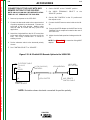
Figure C.3 LN-25 with K431 Remote Option to the V350-PRO
Return to Master TOC
Return to Section TOC
ELECTRODE CABLE
TO LN-25
TO
WORK
14 PIN (24/42VAC)
AMPHENOL
6 PIN AMPHENOL
LN-25 WITH
K431 OPTION
+
K876 ADAPTER
K432 REMOTE
CONTROL CABLE
INVERTEC
POWER SOURCE
Return to Master TOC
NOTE: Illustration shows electrode connected for positive polarity.
Return to Section TOC
the
V350-PRO
Return to Master TOC
Return to Section TOC
C-5
C-5
ACCESSORIES
CONNECTION OF THE K867 ADAPTER
FOR USE WITH LN-25 WITH K431
OPTION/V350-PRO.
1. Insulate each unused lead individually.
2. Remove 6 pin plug from K432 cable in order to
connect K867 adapter.
3. Label each lead (A thru F) as they are removed
from the 6 pin plug.
Return to Master TOC
Return to Section TOC
4. Splice leads and insulate.
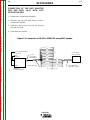
Figure C.4 Connection of LN-25 to V350-PRO using K867 adapter.
21
82
81
42
ELECTRODE CABLE
TO LN-25
TO
WORK
14 PIN
(24/42VAC)
31
32
Return to Section TOC
Return to Master TOC
Return to Section TOC
Return to Master TOC
K867 ADAPTER
LN-25 WITH
K431 OPTION
GND
AMPHENOL
+
1
41
2
E
4
F
SPARE
D
75
A
76
B
77
C
INVERTEC
4
POWER SOURCE
V350-PRO
K432 REMOTE
CONTROL CABLE
Return to Master TOC
Return to Section TOC
C-6
C-6
ACCESSORIES
CONNECTION OF THE LN-7 TO THE V350PRO USING K480 CONTROL CABLE (SEE
FIGURE C.5)
3. Connect the input cable from the K480 control
cable to the (115VAC) 14 pin amphenol on the
V350-PRO and the input cable plug on the LN-7.
NOTE: AN LN-7 CAN ONLY BE USED WITH A FACTORY OR “CE” VERSION OF THE V350-PRO. IF
YOUR LN-7 COMES EQUIPPED WITH A K291 OR
K404 INPUT CABLE, REFER TO THE CONNECTION
OF THE LN-7 USING K867 UNIVERSAL ADAPTER.
4. Set the “VOLTMETER” switch to “+” or “-”
depending on the polarity chosen.
5. Set “CONTROL SELECT” to “REMOTE”.
6. Set the “MODE” to the “CV-WIRE” position.
1. Remove input power to the V350-PRO.
Return to Master TOC
Return to Section TOC
2. Connect the electrode cable from the K480 control
cable to the “+” terminal of the welder and to the
LN-7 wire feeder. Connect the work cable to the
“-” terminal of the welder.
NOTE: Figure C.5 shows the electrode connected
for positive polarity. To change polarity, shut the
welder off and reverse the electrode and work
cables at the output terminals.
7. Place the “WELD TERMINALS SELECT” in the
“REMOTE” position.
8. Adjust wire feed speed at the LN-7 and adjust the
welding voltage with the optional remote control if
used.
9. Set the “ARC” control at “0” initially and adjust to
suit.
NOTE: Welding cable must be sized for current
and duty cycle of application.
Figure C.5 V350-PRO/LN-7 with K480 Control Cable Connection Diagram
Return to Section TOC
Return to Master TOC
Return to Section TOC
Return to Master TOC
TO LN-7 INPUT
14 PIN
AMPHENOL
(115VAC)
AT REAR OF
MACHINE
CABLE PLUG
OPTIONAL K857
REMOTE CONTROL
-
+
K480 CONTROL CABLE
6 PIN
AMPHENOL
ELECTRODE CABLE
TO WIRE FEED UNIT
TO WORK
V350-PRO
Return to Master TOC
Return to Section TOC
C-7
C-7
ACCESSORIES
CONNECTION OF THE K867 ADAPTER
FOR USE WITH THE K291 OR K404 INPUT
CABLES AND LN-7.
1. Insulate each unused lead individually.
2. Splice leads and insulate.
Return to Master TOC
Return to Section TOC
Figure C.6 Connection of LN-7 to V350-PRO using K867 adapter.
SPARE
82
ELECTRODE CABLE
TO LN-7
TO
WORK
81
14 PIN(115VAC)
AMPHENOL
+
INVERTEC
POWER SOURCE
K867 UNIVERSAL
ADAPTER PLUG
BOX
42
41
31
31
32
32
2
2
4
4
21
21
GND
GND
75
75
76
76
77
77
GREEN
Return to Section TOC
Return to Master TOC
Return to Master TOC
2
Return to Section TOC
LN-7
CONTROL
1
V350-PRO
K291 OR K404
INPUT CABLE
K775 OPTIONAL
REMOTE CONTROL
Return to Master TOC
Return to Section TOC
C-8
ACCESSORIES
CONNECTION OF THE LN-742 TO THE
V350-PRO (SEE FIGURE C.7)
NOTE: AN LN-7 CAN ONLY BE USED WITH A FACTORY OR “CE” VERSION OF THE V350-PRO.
Return to Master TOC
Return to Section TOC
Return to Master TOC
Return to Master TOC
4. Set the “VOLTMETER” switch to “+” or “-”
depending on the polarity chosen.
5. Set the “MODE” to the “CV-WIRE” position..
2. Connect the electrode cable from the LN-742 to
the “+” terminal of the welder. Connect the work
cable to the “-” terminal of the welder.
NOTE: Welding cable must be sized for current
and duty cycle of application.
6. Set “CONTROL SELECT” to “LOCAL”.
7. Place the “WELD TERMINALS SELECT” in the
“REMOTE” position.
8. Adjust wire feed speed at the LN-742.
9. Set the “ARC” control at “0” initially and adjust to
suit.
Figure C.7 V350-PRO/LN-742 Connection Diagram
TO LN-742 INPUT
14 PIN
AMPHENOL
(24/42VAC)
AT REAR OF
MACHINE
Return to Section TOC
3. Connect the K591 control cable to the 24/42VAC
14 pin amphenol on the back of the V350-PRO
and the input cable plug on the LN-742.
1. Remove input power to the V350-PRO.
NOTE: Figure C.7 shows the electrode connected
for positive polarity. To change polarity, shut the
welder off and reverse the electrode and work
cables at the output terminals.
Return to Section TOC
C-8
CABLE PLUG
+
-
K591 CONTROL CABLE
ELECTRODE CABLE
TO WIRE FEED UNIT
TO WORK
V350-PRO
Return to Master TOC
Return to Section TOC
C-9
ACCESSORIES
CONNECTION OF THE LN-10 TO THE
V350PRO USING THE K1505 CONTROL CABLE.
NOTE: AN LN-10 CAN ONLY BE USED WITH A FACTORY OR “CE” VERSION OF THE V350-PRO.
1. Remove input power to the V350-PRO.
2. Connect the K1505 control cable from the LN-10
to the Invertec 24/42VAC 14 pin amphenol connecter on the rear of the V350-PRO.
Return to Master TOC
3. Connect the electrode cable to the output terminal
of polarity required by the electrode. Connect the
work lead to the other terminal.
Return to Section TOC
C-9
4. Set the meter polarity switch on the front of the
V350-PRO to coincide with wire feeder polarity
used.
5. Set “CONTROL SELECT” to “REMOTE”.
8. Set the “ARC CONTROL” to the “0” position and
then adjust to suit.
9. Set wire feed speed and voltage at the LN-10.
NOTE: The voltage set point displayed on the
V350-PRO should be ignored when operating in
the remote control mode with the LN-10.
10. See the LN-10 manual for details on accessing
the control DIP switch.
11. The control DIP switch inside the LN-10 should be
set as shown below for operation with the V350Pro.
Power Sources
ON
1
2
3
4
5
6
7
8
S1
S1
6. Set the “MODE” to the “CV-WIRE” position..
7. Set the “WELD TERMINALS SELECT” to the
“REMOTE” position.
Return to Master TOC
Return to Section TOC
Figure C.8 LN-10 V350-PRO
TO LN-10
14 PIN
AMPHENOL
(24/42VAC)
AT REAR OF
MACHINE
+
-
K1505
TO WORK
Return to Master TOC
Return to Section TOC
ELECTRODE CABLE
TO LN-10
V350-PRO
C-10
C-10
Return to Master TOC
Return to Section TOC
ACCESSORIES
OPTIONS / ACCESSORIES
Cobramatic Connection Instructions
A Cobramatic can only be used with a Factory or
"CE" version of the V350
Construction Version – K1728-2
1. Turn the Invertec power switch "off"
2. Connect the control cable from the Cobramatic to
the 24/42 VAC 14-pin wire feeder amphenol on
the rear of the Invertec.
3. Connect the electrode cable to the output terminal
of the polarity required by electrode. Connect the
work lead to the other terminal.
Return to Master TOC
Return to Section TOC
4. Set the meter polarity switch on the front of the
Invertec to coincide with wire feeder polarity used.
5. If a remote control such as K857 is to be used
with the Cobramatic, the remote can be connected
directly to the 6pin amphenol on the front of the
Invertec or use a K864 adapter to connect the
cobramatic and the remote to the 24/42VAC 14pin wire feeder amphenol connector on the rear of
the Invertec.
TIG Module K930-2
The TIG Module connects to the V350-Pro Factory or
CE versions with a K936-1 (9-14 pin) control cable.
Connect the K936-1 to the 115VAC Wire Feeder
Amphenol on the rear of the V350-Pro.
• All welding modes for this model run with local output control and weld terminals ON (e.g. Stick, TIG,
LN25 off the arc).
K930-1
TIG Module
K428,K446, K449
LN-25(Off the Arc)
Factory Version – K1728-1
• The factory model is the construction model with
the addition of the Wire Feeder/Remote Adapter.
• In this form, the V350-Pro provides the hardware to
power and connect to 24, 42 or 115 VAC wire feeders.
K857
Remote Output Control
K814
Arc Start Switch
K812
Hand Operated Amptrol
K870
Foot Operated Amptrol
K930-1
TIG Module
K428, K446, K449
LN-25
K617 (-1 or -2) K618 (-1 or -2)
LN-742
K440 (-1), K567-1
LN-7 GMA
K1559-1, K1564-1
LN-10
K1499-1, K1521-1
DH-10
Return to Master TOC
Return to Section TOC
"CE" Version – K1728-3
The TIG Module can also be used with the V350
Construction version. A K936-4 control cable is
required to supply 115VAC to the TIG Module from an
external 115VAC supply.
General Instructions for Connection of Wire
Feeders to V350-Pro
Wire feeders other than LN-7 and LN-25 may be used
provided that the auxiliary power supply capacity of
the V350-Pro is not exceeded. K867 universal
adapter plug is required. See connection diagram
S19406 and S19386 at the back of this manual for
more information.
Remote Control of Invertec
Remote Control K857, Hand Amptrol K963 and Foot
Amptrol K870.
• The "CE" version is the Factory version with the
addition of power line filtering allowing the machine
to comply with the European and Australian EMC
emission requirements.
Field Installed Options/Accessories
Two versions of the V350-Pro are available from the
factory for both the CE and ROW versions.
Options for K1728-1 Factory and K1728-3 "CE"
V350’s
• TIG Gas Control Kit – K1762-1
• Advance Process Panel – K1763-1
Return to Master TOC
Return to Section TOC
Options for all models of V350-PRO
• Undercarriage – K1764-1
V350-PRO
Return to Master TOC
Section D-1
Section D-1
TABLE OF CONTENTS
-MAINTENANCEMaintenance .........................................................................................................................Section D
Input Filter Capacitor Discharge Procedure ...............................................................................D-2
Routine Maintenance..................................................................................................................D-2
Periodic Maintenance .................................................................................................................D-3
Thermal Protection .....................................................................................................................D-3
Return to Master TOC
Return to Master TOC
Return to Master TOC
Major Component Locations .....................................................................................................D-4
V350-PRO
Return to Master TOC
Return to Master TOC
Return to Section TOC
Return to Section TOC
D-2
MAINTENANCE
FIGURE D.1 — LOCATION OF INPUT FILTER
CAPACITOR TERMINALS
WARNING
Do not put your hands near the cooling blower
fan. If a problem cannot be corrected by
following the instructions, take the machine to
the nearest Lincoln Field Service Shop.
----------------------------------------------------------------------ELECTRIC SHOCK can kill.
• Do not touch electrically live parts or
electrode with skin or wet clothing.
• Insulate yourself from work and
ground
• Always wear dry insulating gloves.
------------------------------------------------------------------------
EXPLODING PARTS can cause
injury.
• Failed parts can explode or cause other
parts to explode when power is applied.
Return to Master TOC
See additional warning information
throughout this operators manual.
-----------------------------------------------------------Return to Section TOC
INPUT FILTER CAPACITOR
DISCHARGE PROCEDURE
-
+
-
+
INSULATED
PLIERS
-
+
-
POWER
RESISTOR
+
INSULATED
GLOVES
5. Locate the eight capacitor terminals shown in figure D.1.
6. Using electrically insulated gloves and pliers, hold
the body of the resistor with the pliers and connect
the resistor leads across the two capacitor terminals. Hold the resistor in place for 10 seconds.
DO NOT TOUCH CAPACITOR TERMINALS WITH
YOUR BARE HANDS.
7. Repeat the discharge procedure for the other
three capacitors.
8. Check the voltage across the terminals of all
capacitors with a DC voltmeter. Polarity of the
capacitor terminals is marked on the PC board
above the terminals. Voltage should be zero. If
any voltage remains, repeat this capacitor discharge procedure.
ROUTINE MAINTENANCE
1. Remove the input power to the V350-PRO.
2. Using the 5/16” wrench remove the screws from
the case wraparound cover.
3. Be careful not to make contact with the capacitor
terminals located at the top and bottom of the
switch board.
Return to Master TOC
EIGHT
CAPACITOR
TERMINALS
Have qualified personnel do the maintenance
work. Always use the greatest care when
working near moving parts.
• Always wear a face shield and long sleeves when servicing.
------------------------------------------------------------------------
Return to Section TOC
D-2
4. Obtain a high resistance and high wattage resistor (25-1000 ohms and 25 watts minimum). This
resistor is not with the machine. NEVER USE A
SHORTING STRAP FOR THIS PROCEDURE.
1. Every 6 months or so the machine should be
cleaned with a low pressure airstream. Keeping the
machine clean will result in cooler operation and
higher reliability. Be sure to clean these areas:
•
•
•
•
•
•
All printed circuit boards
Power switch
Main transformer
Input rectifier
Auxiliary Transformer
Reconnect Switch Area
2. Examine the sheet metal case for dents or breakage.
Repair the case as required. Keep the case in good condition to insure that high voltage parts are protected and
correct spacings are maintained. All external sheet metal
screws must be in place to insure case strength and electrical ground continuity.
V350-PRO
Return to Master TOC
Return to Section TOC
D-3
MAINTENANCE
OVERLOAD PROTECTION
The machine is electrically protected from producing
high output currents. Should the output current exceed
430A, an electronic protection circuit will reduce the
current to approximately 100A. The machine will continue to produce this low current until the protection circuit is reset. Reset occurs when the output load is
removed.
Return to Master TOC
Return to Master TOC
Return to Master TOC
Return to Section TOC
Return to Section TOC
Return to Section TOC
THERMAL PROTECTION
Thermostats protect the machine from excessive operating temperatures. Excessive temperatures may be
caused by a lack of cooling air or operating the
machine beyond the duty cycle and output rating. If
excessive operating temperature should occur, the
thermostat will prevent output voltage or current. The
meter will remain energized during this time.
Thermostats are self-resetting once the machine cools
sufficiently. If the thermostat shutdown was caused by
excessive output or duty cycle and the fan is operating
normally, the Power Switch may be left on and the
reset should occur within a 15 minute period.
V350-PRO
D-3
R
WE
PO
V350-PRO
Return to Master TOC
!
4
1
Return to Master TOC
5
Return to Master TOC
3
Return to Section TOC
y qu co ism t
lor mmmy ali et eu erat
a
h era
do nu
num gn am
am
um no
sit y nib qu
ma
ips m e lor my ali
dia lor do ummm a
n gn
nu
rem ed do
Lo t, t um no ma
eli ree ips m e
lao rem dia lor
ed do
Lo t, t
eli ree
lao
F
OF
RO
-P
50
A
A T
PR VIS TEN
EC O D TIO
AU E N
CIO
N
!
Return to Section TOC
!
W
WA ARN
IN
RN
G
IN
G
g
cin
pis
ut
adi
nt
er
g
idu
tetu
cin
tinc
pis
sec od
ut
adi
con sm
nt
er
et eui att
idu
g
am h
erera tetu tinc
cin
nib
sit
sec od
pis
y
uam
or my
ut
m
adi
con sm
g
nt
dol um aliq et
er
eui att
cin
idu
um non gna am h
erera tetu
pis
tinc
ips m ma sit
nib
ut
adi
y
uam sec od
nt
em dia ore or mmy
er
con sm
idu
Lor , ed dol dol um aliq et
eui att tetu tinc
t um
non gna am h
ererasec
elit
ree ips m ma
od
nib
sit
y
lao em dia
uamcon sm
g
m
ore or my
et eui att
dol um aliq
Lor , ed dol
cin
am h
erera
t
pis
um non gnasit
nib
elit
ut
ree ips
y
uam
adi
m maor mmy
nt
lao
er
em dia oredol um aliq
idu
g
tetu
Lor , ed dolum non gna
cin
tinc
t ips m
sec od
pis
ma
elit
ree
ut
con sm
adi
em dia ore
g
nt
lao ed
et
er
eui att
cin
Lor ,
idu
t dol
am h
erera tetu
pis
elit
tinc
ut
nib
sit
ree
adi
y
uam sec od
g
nt
or my
lao
m
er
cin
idu
dol um aliq con sm
g
tetu
et eui att
pis
tinc
um non gna
ut
cin
sec od
am h
erera
adi
ips m ma
nt
pis
er
nib
sit
con
ut
sm
idu
y
adi
uam
em dia ore
or my
et eui att tetu
nt
m
er
tinc
Lor , ed dol
dol um aliq
g
am h
ererasec
idu
t
od
tetu
cin
nib
sit
elit
um non gna
tinc
ree
uamcon sm
pis
or mmyy
sec od
ips m ma
t
et
ut
lao
adi
dol um aliq h eui at
con sm
nt
em dia ore
am
erera
ing
er
et eui att
um non gnasit
idu
nib
g
Lor , ed dol
sc
am h
erera tetu tinc
t
uam
ips m maor mmyy
cin
ipi ut
elit
nib
sit
sec od
ree
pis
em dia ore dol um aliq
y
ad t
uam
or my
ut
m
lao
adi
r un
con sm
Lor , ed dolum non gna
nt
ing
dol um aliq et
t ips
er
ue cid
eui att
m ma
idu
elit
sc
um non gna am h
ree
erera tetu
tet tin
g
em dia ore
ipi ut
tinc
ips m ma sit
nib
lao
cin
ec
y
Lor , ed dol
uam sec od
ad t
em dia ore or mmy
t
pis
r un
ns od
con sm
elit
ut
Lor , ed dol dol um aliq et
adi
ree
t
co ism t ue cid
nt
t
um non gna am h eui ereraat
at tet
er
lao
elit
et eu era
tin
idu
ree ips m ma
nib
h er ec
sit
tetu
tinc
y
lao em dia
am
g
uam
sec od
ore or mmy
am ns od
cin
dol um aliq
sit y nib qu co ism t
Lor , ed dol
con sm
pis
t
um non gna
ut
et eui att
elit
lor mmmy ali et eu at
adi
ree ips
er
nt
a
h era
am h
erera
m ma
do nu
er
g
lao
num gn am
idu
nib
sit
em dia
cin
am
ore
tetu
uam
um no
or mmyy
sit y nib qu
tinc
pis
Lor , ed dol
ma
sec od
ut
t
dol um aliq
ips m e lor my ali
adi
elit
nt
con sm
ree
er
um non gna
dia lor do ummm a
idu
et eui att
n gn
nu
lao
ips m ma
rem ed do
am h
erera tetu tinc
Lo t, t um no ma
em dia ore
sec od
nib
sit
y
g
uamcon
eli ree ips m e
Lor , ed dol
or my
m
sm
t
cin
dol um aliq et eui att
elit
lao rem dia lor
pis
ree
erera
ut
um non gna am h
ed do
adi
lao
Lo t, t
nt
ips m ma sit y nib
er
uam
or mmy
idu
eli ree
em dia ore dol
tetu
um aliq
tinc
Lor , ed dol
lao
sec od
t um non gna
ing
elit
con sm
ree ips m ma
sc
et eui att
lao em dia ore
ipi ut
am h
erera
Lor , ed dol
ad t
nib
sit
t
r un
elit
uam
or mmyy
ing
ree
ue cid
dol um aliq
sc
lao
tet tin
ipi ut
um non gna
ec
ad t
ips m ma
r un
ns od
em dia ore
co ism t ue cid
Lor , ed dol
at tet
et eu era
tin
t
h er ec
elit
ree
am
am ns od
lao
sit nib
UT
TP
V3
EC
TE
MO
RT
RE
SE
LE
CT
VE
IN
ING
RN
WA
TE
RM
IN
AL
S
WE
LD
C
ELOLN
EC
TR
IC
LIN
2
Return to Section TOC
Center Panel
Base Assembly
Control Box Assembly
Case Back
Case Front
Case Wraparound
FIGURE D.2 – MAJOR COMPONENT LOCATIONS
Return to Section TOC
Return to Master TOC
1.
2.
3.
4.
5.
6.
D-4
MAINTENANCE
D-4
6
!
A
AM
PS
A
OU
V
VO
LTS
ON
Return to Master TOC
Section E-1
Section E-1
TABLE OF CONTENTS
-THEORY OF OPERATION SECTIONTheory of Operation .............................................................................................................Section E
General Description ....................................................................................................................E-2
Input Line Voltage, Auxiliary Transformer and Precharge...........................................................E-2
Switch Board and Main Transformer ..........................................................................................E-3
Power board, Control Board, and SPI Communications............................................................E-4
Output Rectifier and Choke ........................................................................................................E-5
Thermal Protection .....................................................................................................................E-6
Protection Circuits ......................................................................................................................E-6
Return to Master TOC
Over current Protection ........................................................................................................E-6
Under/Over Voltage Protection ............................................................................................E-6
Insulated Gate Bipolar Transistor (IGBT) Operation ...................................................................E-7
Pulse Width Modulation..............................................................................................................E-8
Minimum/Maximum Output..................................................................................................E-8
FIGURE E.1 – V350-PRO BLOCK LOGIC DIAGRAM
To Control
Board
Main Switch Board
Current
Feedback
& 100A Breaker
Input
Rectifier
Positive
Output
Terminal
Primary
Current
Sensor
Choke
Negative
Output
Terminal
Output Voltage Sense
Reconnect
Switch
Primary
Current
Sensor
115VAC Fan Supply
Auxiliary
115VAC, 42VAC Transformer
24VAC
Fan Control
Fan
Primary Current Feedback
Input Relay Control
Soft Start Control
V/F Capacitor Feedback (2)
IGBT Drive Signal
Return to Master TOC
Input switch
Machine Control Supply
+15VDC, -15VDC, +6VDC
Power
Board
28VAC
Return to Master TOC
14 Pin
Amphenol
40VDC
SPI Supply +15VDC +5VDC
Control Board
RS232 Supply +5VDC
SPI Communications
Solenoid Supply
40VDC
6 Pin
Amphenol
Remote
Board
Mode
Panel
Remote Control & Trigger
Optional Solenoid
V350-PRO
& +15VDC, +5VDC Supply
Status
Panel
Display
Panel
THEORY OF OPERATION
FIGURE E.2 – INPUT VOLTAGE AND PRECHARGE
To Control
Board
Main Switch Board
Input switch
& 100A Breaker
Input
Rectifier
Positive
Output
Terminal
Primary
Current
Sensor
Choke
Primary
Current
Sensor
Return to Master TOC
Auxiliary
115VAC, 42VAC Transformer
24VAC
Primary Current Feedback
Input Relay Control
Soft Start Control
V/F Capacitor Feedback (2)
IGBT Drive Signal
115VAC Fan Supply
Fan Control
Fan
Return to Section TOC
Negative
Output
Terminal
Reconnect
Switch
Output Voltage Sense
Return to Master TOC
E-2
Current
Feedback
Return to Section TOC
E-2
Machine Control Supply
+15VDC, -15VDC, +6VDC
Power
Board
28VAC
40VDC
14 Pin
Amphenol
SPI Supply +15VDC +5VDC
Control Board
RS232 Supply +5VDC
SPI Communications
Solenoid Supply
40VDC
6 Pin
Amphenol
Remote
Board
Mode
Panel
& +15VDC, +5VDC Supply
Status
Panel
Display
Panel
Remote Control & Trigger
Return to Master TOC
Return to Master TOC
Return to Section TOC
Return to Section TOC
Optional Solenoid
GENERAL DESCRIPTION
and the resultant 40VDC is applied to the power board.
The Invertec V350-Pro is an inverter based welding
power source that offers multi mode constant voltage
(CV) and constant current (CC) welding and is rated at
350 amps 34VDC at a 60% duty cycle. The Invertec
V350-Pro is available in either a construction version
(no wire feeder connection or auxiliary power ) and a
factory version that includes a wire feeder connection
and related power.
The input voltage is rectified by the input rectifier and
the resultant DC voltage is applied to the switch board
through the reconnect switch assembly located at the
rear of the machine. The reconnect switch connect the
two pairs of input capacitors either in a parallel (lower
voltage) or series (higher voltage) configuration to
accommodate the applied input voltage.
INPUT LINE VOLTAGE, AUXILIARY
TRANSFORMER, & PRECHARGE
The Invertec V350-Pro can be connected for a variety
of three-phase or single-phase input voltages. The initial power is applied to the V350 through a combination line switch/circuit breaker located on the front of
the machine. Two phases of the input voltage are
applied to the auxiliary transformer. The auxiliary transformer develops four different secondary voltages.
The 115VAC is used to power the fan motor and also
is applied to the 14 pin amphenol type connector for
wirefeeder operation. The 24VAC and 42VAC voltages are also applied to the 14 pin amphenol type connector to power wirefeeders. The 28VAC is rectified
During the precharge time the DC input voltage is
applied to the input capacitors through a current limiting circuit. The input capacitors are charged slowly
and current limited. A voltage to frequency converter
circuit located on the switch board monitors the
capacitor voltages. This signal is coupled to the control board. When the input capacitors have charged
to an acceptable level, the control board energizes the
input relays, that are located on the switch board,
making all of the input power, without current limiting,
available to the input capacitors. If the capacitors
become under or over voltage the control board will
de-energize the input relays and the V350 output will
be disabled. Other possible faults may also cause the
input relays to drop out.
NOTE: Unshaded areas of Block Logic Diagram are the subject of discussion.
V350-PRO
To Control
Board
Main Switch Board
Input
Rectifier
Input switch
& 100A Breaker
Positive
Output
Terminal
Primary
Current
Sensor
Choke
Auxiliary
115VAC, 42VAC Transformer
24VAC
Primary Current Feedback
Input Relay Control
Soft Start Control
V/F Capacitor Feedback (2)
IGBT Drive Signal
115VAC Fan Supply
Fan Control
Fan
Return to Master TOC
Negative
Output
Terminal
Reconnect
Switch
Output Voltage Sense
Return to Master TOC
THEORY OF OPERATION
FIGURE E.3 – SWITCH BOARD & MAIN TRANSFORMER
Primary
Current
Sensor
Return to Section TOC
E-3
Current
Feedback
Return to Section TOC
E-3
Machine Control Supply
+15VDC, -15VDC, +6VDC
Power
Board
28VAC
40VDC
14 Pin
Amphenol
SPI Supply +15VDC +5VDC
Control Board
RS232 Supply +5VDC
SPI Communications
Solenoid Supply
40VDC
6 Pin
Amphenol
Remote
Board
Mode
Panel
& +15VDC, +5VDC Supply
Status
Panel
Display
Panel
Remote Control & Trigger
Optional Solenoid
Return to Master TOC
Return to Master TOC
Return to Section TOC
Return to Section TOC
SWITCH BOARD &
MAIN TRANSFORMER
There is one switch board in the Invertec V350-Pro.
This board incorporates two pairs of input capacitors,
two insulated gate bipolar transistor (IGBT) switching
circuits, a fan motor drive circuit, and a voltage/frequency capacitor feedback circuit. The two capacitors in a pair are always in series with each other.
When the reconnect switch is in the lower voltage
position the capacitor pairs are in parallel . Thus two
series capacitors in parallel with two series capacitors.
When the reconnect switch is in the high voltage position the two capacitor pairs are in series. Thus four
capacitors in series. This is required to accommodate
the higher input voltages.
When the input capacitors are fully charged they act
as power supplies for the IGBT switching circuits.
When welding output is required the Insulated Gate
Bipolar Transistors switch the DC power from the input
capacitors, "on and off" thus supplying a pulsed DC
current to the main transformer primary windings. See
IGBT Operation Discussion and Diagrams in this
section. Each IGBT switching circuit feeds current to
a separate, oppositely wound primary winding in the
main transformer. The reverse directions of current
flow through the main transformer primaries and the
offset timing of the IGBT switching circuits induce an
AC square wave output signal at the secondary of the
main transformer. The two current transformers (CT)
located on the switch board monitor these primary
currents. If the primary currents become abnormally
high the control board will shut off the IGBTs, thus disabling the machine output. The DC current flow
through each primary winding is clamped back to
each respective input capacitor when the IGBTs are
turned off. This is needed due to the inductance of the
transformer primary winding. The firing of the two
switch boards occurs during halves of a 50 microsecond interval, creating a constant 20 KHZ output. In
some low open circuit Tig modes the firing frequency
is reduced to 5KHZ.
The Invertec V350-Pro has a F.A.N. fan as needed circuit. The fan operates when the welding output terminals are energized or when a thermal over temperature condition exists. Once the fan is activated it will
remain on for a minimum of five minutes. The fan driver circuit is housed on the switch board but it is activated from a control board signal.
NOTE: Unshaded areas of Block Logic Diagram are the subject of discussion.
V350-PRO
Return to Master TOC
E-4
THEORY OF OPERATION
FIGURE E.4 – POWER BOARD, CONTROL BOARD
AND SERIAL PERIPHERAL INTERFACE (SPI) COMMUNICATIONS
To Control
Board
Main Switch Board
Current
Feedback
Return to Section TOC
E-4
Input switch
& 100A Breaker
Input
Rectifier
Positive
Output
Terminal
Primary
Current
Sensor
Choke
Negative
Output
Terminal
Output Voltage Sense
Reconnect
Switch
Primary
Current
Sensor
Return to Master TOC
Return to Section TOC
Auxiliary
115VAC, 42VAC Transformer
24VAC
Primary Current Feedback
Input Relay Control
Soft Start Control
V/F Capacitor Feedback (2)
IGBT Drive Signal
115VAC Fan Supply
Fan Control
Fan
Machine Control Supply
+15VDC, -15VDC, +6VDC
Power
Board
28VAC
40VDC
14 Pin
Amphenol
SPI Supply +15VDC +5VDC
Control Board
RS232 Supply +5VDC
SPI Communications
Solenoid Supply
40VDC
6 Pin
Amphenol
Remote
Board
Mode
Panel
& +15VDC, +5VDC Supply
Status
Panel
Display
Panel
Remote Control & Trigger
Return to Section TOC
Return to Master TOC
Return to Section TOC
Return to Master TOC
Optional Solenoid
POWER BOARD, CONTROL BOARD
AND SERIAL PERIPHERAL INTERFACE (SPI) COMMUNICATIONS
POWER BOARD
The 28VAC auxiliary is rectified and filtered and applied
to the power board. The power board, utilizing a
switching power supply, processes the 40VDC input
and develops several regulated positive and negative
DC supplies. Three DC supplies are fed to the control
board for machine control supplies. Two positive DC
voltages are coupled to the control board for the Serial
Peripheral Communications (SPI) supplies. A +5VDC
is used for the RS232 connection supply and a
+40VDC is fed to the remote board to power an
optional gas solenoid. An over or under input voltage
detection and shutdown circuit is also part of the
power board’s circuitry.
CONTROL BOARD
functions to establish and maintain output control of
the V350 machine. The control board sends and
receives command signals from the mode panel, the
status panel, the display panel and /or the optional
remote panel. These communications are processed
through a digital network called a Serial Peripheral
Interface (SPI). This network digitally communicates to
and from the control board the user’s commands and
various machine status messages. The software that
is contained within the control board processes and
compares these commands with the voltage and current feedback information it receives from the output
current sensor and the output voltage sensing leads.
The appropriate pulse width modulation (PWM) signals
(See Pulse Width Modulation in this section) are sent
to the switch board IGBTs. In this manner, the digitally controlled high-speed welding waveform is created
and regulated.
The control board also monitors the thermostats, the
main transformer primary currents and the input
capacitor voltages.
The control board performs the primary interfacing
NOTE: Unshaded areas of Block Logic Diagram are the subject of discussion.
V350-PRO
THEORY OF OPERATION
FIGURE E.5 – OUTPUT RECTIFIER AND CHOKE
To Control
Board
Main Switch Board
Input
Rectifier
Input switch
& 100A Breaker
Positive
Output
Terminal
Primary
Current
Sensor
Choke
Primary
Current
Sensor
Return to Master TOC
Auxiliary
115VAC, 42VAC Transformer
24VAC
Primary Current Feedback
Input Relay Control
Soft Start Control
V/F Capacitor Feedback (2)
IGBT Drive Signal
115VAC Fan Supply
Fan Control
Fan
Return to Section TOC
Negative
Output
Terminal
Reconnect
Switch
Output Voltage Sense
Return to Master TOC
E-5
Current
Feedback
Return to Section TOC
E-5
Machine Control Supply
+15VDC, -15VDC, +6VDC
Power
Board
28VAC
14 Pin
Amphenol
40VDC
SPI Supply +15VDC +5VDC
Control Board
RS232 Supply +5VDC
SPI Communications
Solenoid Supply
40VDC
6 Pin
Amphenol
Remote
Board
Mode
Panel
& +15VDC, +5VDC Supply
Status
Panel
Display
Panel
Remote Control & Trigger
Optional Solenoid
Return to Section TOC
Return to Master TOC
Return to Section TOC
Return to Master TOC
OUTPUT RECTIFIER AND CHOKE
The output rectifier receives the AC output from the
main transformer secondary and rectifies it to a DC
voltage level. Since the output choke is in series with
the negative leg of the output rectifier and also in
series with the welding load, a filtered DC output is
applied to the machine’s output terminals.
NOTE: Unshaded areas of Block Logic Diagram are the subject of discussion.
V350-PRO
Return to Master TOC
Return to Master TOC
Return to Section TOC
Return to Section TOC
E-6
THEORY OF OPERATION
OVER CURRENT
PROTECTION
THERMAL PROTECTION
Two normally closed (NC) thermostats protect the
machine from excessive operating temperatures.
These thermostats are wired in series and are connected to the control board. One of the thermostats is
located on the heat sink of the switch board and the
other is located on the output choke. Excessive temperatures may be caused by a lack of cooling air or
operating the machine beyond its duty cycle or output
rating. If excessive operating temperatures should
occur, the thermostats will prevent output from the
machine. The yellow thermal light, located on the front
of the machine, will be illuminated. The thermostats
are self-resetting once the machine cools sufficiently.
If the thermostat shutdown was caused by excessive
output or duty cycle and the fan is operating normally,
the power switch may be left on and the reset should
occur within a 15-minute period. If the fan is not turning or the air intake louvers are obstructed, then the
power must be removed from the machine, and the
fan problem or air obstruction corrected.
PROTECTIVE CIRCUITS
Return to Section TOC
Return to Master TOC
Return to Master TOC
If the average current exceeds 450 amps for one second, then the output will be limited to 100 amps until
the load is removed. If the peak current exceeds 600
amps for 150 ms, the output will be limited to 100
amps until the load is removed.
UNDER/OVER VOLTAGE PROTECTION
Protective circuits are included on the switch and control boards to monitor the voltage across the input
capacitors. In the event that a capacitor pair voltage
is too high, or too low, the machine output will be disabled. The protection circuits will prevent output if any
of the following conditions exist.
1. Voltage across a capacitor pair exceeds 467
volts. (High line surges or improper input voltage
connections.)
2. Voltage across a capacitor pair is under 190 volts.
(Due to improper input voltage connections.)
Protective circuits are designed into the V350-PRO to
sense trouble and shut down the machine before
damage occurs to the machine's internal components.
Return to Section TOC
E-6
3. Internal component damage.
V350-PRO
Return to Master TOC
Return to Master TOC
Return to Section TOC
Return to Section TOC
E-7
E-7
THEORY OF OPERATION
INSULATED GATE BIPOLAR
TRANSISTOR (IGBT)
OPERATION
An IGBT is a type of transistor. IGBT are semiconductors well suited for high frequency switching and high
current applications.
capable of conducting current. A voltage supply connected to the drain terminal will allow the IGBT to conduct and supply current to the circuit components
coupled to the source. Current will flow through the
conducting IGBT to downstream components as long
as the positive gate signal is present. This is similar to
turning ON a light switch.
Example A in Figure E.8 shows an IGBT in passive
mode. There is no gate signal, zero volts relative to the
source, and therefore, no current flow. The drain terminal of the IGBT may be connected to a voltage supply; but since there is no conduction, the circuit will not
supply current to components connected to the
source. The circuit is turned OFF like a light switch.
Example B shows the IGBT in an active mode. When
the gate signal , a positive DC voltage relative to the
source, is applied to the gate terminal of the IGBT, it is
FIGURE E.6 – IGBT
POSITIVE
VOLTAGE
APPLIED
Return to Section TOC
Return to Master TOC
Return to Section TOC
Return to Master TOC
SOURCE
n+
GATE
SOURCE
n+
n+
GATE
n+
p
BODY REGION
p
BODY REGION
n-
DRAIN DRIFT REGION
n-
DRAIN DRIFT REGION
n+
BUFFER LAYER
n+
BUFFER LAYER
p+
INJECTING LAYER
p+
INJECTING LAYER
DRAIN
DRAIN
B. ACTIVE
A. PASSIVE
V350-PRO
Return to Master TOC
Return to Section TOC
E-8
E-8
THEORY OF OPERATION
FIGURE E.9 — TYPICAL IGBT OUTPUTS.
sec
48
50
sec
sec
sec
Return to Master TOC
Return to Section TOC
MINIMUM OUTPUT
24 sec
24 sec
2 sec
50 sec
MAXIMUM OUTPUT
MAXIMUM OUTPUT
Return to Master TOC
Return to Section TOC
PULSE WIDTH
MODULATION
The term Pulse Width Modulation is used to describe
how much time is devoted to conduction in the positive and negative portions of the cycle. Changing the
pulse width is known as modulation. Pulse Width
Modulation (PWM) is the varying of the pulse width
over the allowed range of a cycle to affect the output
of the machine.
MINIMUM OUTPUT
By holding the gate signal on for 24 microseconds
each, and allowing only two microseconds of dwell
time (off time) during the 50-microsecond cycle, the
output is maximized. The darkened area under the top
curve can be compared to the area under the bottom
curve. The more dark area that is under the curve indicates that more power is present.
1An IGBT group
modules feeding
winding.
Return to Master TOC
Return to Section TOC
By controlling the duration of the gate signal, the IGBT
is turned on and off for different durations during the
cycle. The top drawing in Figure E.9 shows the minimum output signal possible over a 50-microsecond
time period.
The positive portion of the signal represents one IGBT
group1 conducting for one microsecond. The negative
portion is the other IGBT group1. The dwell time (off
time) is 48 microseconds (both IGBT groups off). Since
only two microseconds of the 50-microsecond time
period is devoted to conducting, the output power is
minimized.
V350-PRO
consists of two IGBT
one transformer primary
Section F-1
TABLE OF CONTENTS
TROUBLESHOOTING & REPAIR SECTION
Troubleshooting & Repair Section .................................................................................Section F
How to Use Troubleshooting Guide ....................................................................................F-2
PC Board Troubleshooting Procedures and Replacement .................................................F-3
Troubleshooting Guide ........................................................................................................F-4
Test Procedures
Input Filter Capacitor Discharge Procedure .................................................................F-15
Main Switch Board Test ................................................................................................F-17
Input Rectifier Test ........................................................................................................F-21
Power Board Test..........................................................................................................F-25
Output Diode Modules Test ..........................................................................................F-29
Auxiliary Transformer Test .............................................................................................F-33
Current Transducer Test ................................................................................................F-37
Fan Control and Motor Test ..........................................................................................F-41
SPI Cable Resistance and Voltage Test........................................................................F-45
Voltage and Current Calibration Procedure ..................................................................F-47
Replacement Procedures
Control Board Removal and Replacement ...................................................................F-51
Display Board Removal and Replacement ...................................................................F-57
Main Switch Board Removal and Replacement ...........................................................F-61
Mode Board Removal and Replacement......................................................................F-65
Status Board Removal and Replacement.....................................................................F-71
Snubber Board Removal and Replacement .................................................................F-75
Power Board Removal and Replacement.....................................................................F-77
Input Rectifier Removal and Replacement ...................................................................F-81
Output Rectifier Modules Removal and Replacement .................................................F-85
Current Transducer Removal and Replacement ...........................................................F-89
Retest after Repair ........................................................................................................F-94
Return to Master TOC
Return to Master TOC
Return to Master TOC
Return to Master TOC
Section F-1
V350-PRO
Return to Master TOC
Return to Master TOC
Return to Master TOC
Return to Section TOC
Return to Section TOC
Return to Section TOC
F-2
TROUBLESHOOTING & REPAIR
HOW TO USE TROUBLESHOOTING GUIDE
CAUTION
Service and repair should be performed by only Lincoln Electric Factory Trained Personnel.
Unauthorized repairs performed on this equipment may result in danger to the technician and machine
operator and will invalidate your factory warranty. For your safety and to avoid Electrical Shock, please
observe all safety notes and precautions detailed throughout this manual.
This Troubleshooting Guide is provided to help
you locate and repair possible machine
malfunctions. Simply follow the three-step
procedure listed below.
Step 1. LOCATE PROBLEM (SYMPTOM). Look
under the column labeled “PROBLEM
(SYMPTOMS)”. This column describes possible
symptoms that the machine may exhibit. Find
the listing that best describes the symptom that
the machine is exhibiting. Symptoms are
grouped into three main categories: Output
Problems, Function Problems, and LED Function
Problems.
Step 2. PERFORM EXTERNAL TESTS. The
second column, labeled “POSSIBLE AREAS OF
MISADJUSTMENT(S)”, lists the obvious external
possibilities that may contribute to the machine
symptom. Perform these tests/checks in the
order listed. In general, these tests can be
conducted without removing the case
wrap-around cover.
Step 3. PERFORM COMPONENT TESTS. The
last column, labeled “Recommended Course of
Action” lists the most likely components that may
have failed in your machine. It also specifies the
appropriate test procedure to verify that the
subject component is either good or bad. If there
are a number of possible components, check the
components in the order listed to eliminate one
possibility at a time until you locate the cause of
your problem.
All of the referenced test procedures referred to in
the Troubleshooting Guide are described in detail
at the end of this chapter. Refer to the
Troubleshooting and Repair Table of Contents to
locate each specific Test Procedure. All of the
referred to test points, components, terminal
strips, etc., can be found on the referenced
electrical wiring diagrams and schematics. Refer
to the Electrical Diagrams Section Table of
Contents to locate the appropriate diagram.
Return to Master TOC
Return to Section TOC
CAUTION
If for any reason you do not understand the test procedures or are unable to perform the test/repairs
safely, contact the Lincoln Electric Service Department for electrical troubleshooting assistance before
you proceed. Call 1-800-833-9353.(WELD)
V350-PRO
F-2
Return to Master TOC
Return to Master TOC
Return to Section TOC
Return to Section TOC
F-3
TROUBLESHOOTING & REPAIR
PC BOARD TROUBLESHOOTING PROCEDURES
WARNING
ELECTRIC SHOCK can kill.
Have an electrician install and service
this equipment. Turn the machine OFF
before working on equipment. Do not
touch electrically hot parts.
Sometimes machine failures appear to be due to PC
board failures. These problems can sometimes be
traced to poor electrical connections. To avoid problems when troubleshooting and replacing PC boards,
please use the following procedure:
Return to Master TOC
Return to Section TOC
• If the PC Board uses protective shorting jumpers,
don’t remove them until installation is complete.
• If you return a PC Board to The Lincoln Electric
Company for credit, it must be in the static-shielding
bag. This will prevent further damage and allow
proper failure analysis.
4. Test the machine to determine if the failure symptom has been corrected by the replacement PC
board.
NOTE: Allow the machine to heat up so that all
electrical components can reach their
operating temperature.
2. Check for loose connections at the PC board to
assure that the PC board is properly connected.
5. Remove the replacement PC board and substitute
it with the original PC board to recreate the original
problem.
a. If the original problem does not reappear
by substituting the original board, then the
PC board was not the problem. Continue
to look for bad connections in the control
wiring harness, junction blocks, and terminal strips.
PC Board can be damaged by
static electricity.
ATTENTION
Static-Sensitive
Devices
Handle only at
Static-Safe
Workstations
Reusable
Container
Do Not Destroy
Return to Master TOC
• Remove the PC Board from the static-shielding bag
and place it directly into the equipment. Don’t set
the PC Board on or near paper, plastic or cloth which
could have a static charge. If the PC Board can’t be
installed immediately, put it back in the staticshielding bag.
1. Determine to the best of your technical ability that
the PC board is the most likely component causing the failure symptom.
3. If the problem persists, replace the suspect PC
board using standard practices to avoid static
electrical damage and electrical shock. Read the
warning inside the static resistant bag and perform
the following procedures:
Return to Section TOC
F-3
• Remove your body’s static
charge before opening the staticshielding bag. Wear an anti-static wrist strap. For safety, use a
1 Meg ohm resistive cord connected to a grounded part of the
equipment frame.
• If you don’t have a wrist strap,
touch an unpainted, grounded,
part of the equipment frame.
Keep touching the frame to
prevent static build-up. Be sure
not to touch any electrically live
parts at the same time.
b. If the original problem is recreated by the
substitution of the original board, then the
PC board was the problem. Reinstall the
replacement PC board and test the
machine.
6. Always indicate that this procedure was followed
when warranty reports are to be submitted.
NOTE: Following this procedure and writing on the
warranty report, “INSTALLED AND SWITCHED
PC BOARDS TO VERIFY PROBLEM,” will help
avoid denial of legitimate PC board warranty
claims.
• Tools which come in contact with the PC Board must
be either conductive, anti-static or static-dissipative.
V350-PRO
Return to Master TOC
TROUBLESHOOTING & REPAIR
PROBLEMS
(SYMPTOMS)
POSSIBLE AREAS OF
MISADJUSTMENT(S)
Return to Master TOC
RECOMMENDED
COURSE OF ACTION
OUTPUT PROBLEMS
Major physical or electrical damage is evident when the sheet
metal cover is removed.
1. Contact your local authorized
Lincoln Electric Field Service
Facility for technical assis
tance.
1. Contact the Lincoln Electric
Service Department,
The machine is dead—no output—no displays.
1. Make sure the input line/
breaker switch is in the ON
position.
1. Perform the Auxiliary
Transformer Test.
1-800-833-9353(WELD).
2. Perform the Power Board Test.
2. Check the main input line fuses.
If open , replace.
3. Check the 2 amp circuit breaker
(CB2). Reset if tripped.
4. Make sure the reconnect switch
and jumper lead is configured
correctly for the applied input
voltage.
3. The control rectifier and or
associated filter capacitor (C5)
may be faulty. Check and
replace as necessary.
4. Perform The SPI Cable
Resistance and Voltage Test.
5. The Control Board may be
faulty.
5. If the machine is being operated with single phase input voltage make sure the red lead is
not connected. See the
Installation Section.
The main input fuses (or breaker)
repeatedly fail.
1. Make certain the fuses or
breakers are sized properly.
2. Make sure the reconnect switch
and jumper lead is configured
correctly for the applied input
voltage.
3. The welding procedure may be
drawing too much input
current or the duty cycle may
be too high. Reduce the
welding current and /or reduce
the duty cycle.
Return to Section TOC
F-4
TROUBLESHOOTING GUIDE
Observe Safety Guidelines
detailed in the beginning of this manual.
Return to Master TOC
Return to Master TOC
Return to Section TOC
Return to Section TOC
Return to Section TOC
F-4
1. Check the reconnect switches
and associated wiring. See the
wiring diagram.
2. Perform the Input Rectifier
Test.
3. Perform the Main Switch
Board Test.
4. Perform the Output Diode
Module Test.
5. The Input Filter Capacitors
may be faulty. Check, and if
any are faulty replace all four.
CAUTION
If for any reason you do not understand the test procedures or are unable to perform the test/repairs safely, contact the Lincoln Electric Service Department for electrical troubleshooting assistance before you proceed. Call
1-800-833-9353(WELD).
V350-PRO
Return to Master TOC
TROUBLESHOOTING & REPAIR
TROUBLESHOOTING GUIDE
PROBLEMS
(SYMPTOMS)
The V350-Pro does not have welding output. The displays are lit.
Return to Master TOC
POSSIBLE AREAS OF
MISADJUSTMENT(S)
1. Make sure the reconnect switch
is configured correctly for the
input voltage applied.
3. Put the Control Select in the
Local position. If the problem is
solved the remote control
device or associated circuitry
may be faulty.
4. If an error code is displayed see
Fault Code Explanations.
1. The input voltage may be too
low, limiting the output
capability of the machine.
Make certain the input voltage
is correct for the machine and
the reconnect switch and
jumper lead configuration.
2. The welding current may be too
high . The machine will foldback to 100 amps if the
welding current exceeds 450
amps.
3. Make sure the machine is in
"Local" output control.. If the
problem is resolved the Remote
control board or the external
remote control unit may be
faulty.
Return to Master TOC
Return to Section TOC
Observe Safety Guidelines
detailed in the beginning of this manual.
2. Make sure the Weld Terminals
Select is ON. If the problem is
solved the remote control
device or associated circuitry
may be faulty. See the wiring
diagram.
The V350-Pro will not produce full
output.
Return to Section TOC
F-5
RECOMMENDED
COURSE OF ACTION
OUTPUT PROBLEMS
Return to Master TOC
Return to Section TOC
Return to Section TOC
F-5
1. Check the reconnect switch and
associated leads for loose or
faulty connections. See the
wiring diagram.
2. Perform the Main Switch
Board Test.
3. Perform the Power Board
Test.
4. Perform the Output Diode
Module Test.
5. The control board may be faulty.
6. The input filter capacitors may
be faulty. Check and replace if
necessary.
7. The status panel board may be
faulty.
1. Perform the Output Rectifier
Test.
2. Perform the Main Switch
Board Test.
3. Perform the Power Board
Test.
4. Perform the Current
Transducer Test.
5. If the preset function is not
performing properly the status
panel board or the output
control may be faulty.
6. The control board may be faulty.
CAUTION
If for any reason you do not understand the test procedures or are unable to perform the test/repairs safely, contact the Lincoln Electric Service Department for electrical troubleshooting assistance before you proceed.
Call 1-800-833-9353(WELD).
V350-PRO
Return to Master TOC
Return to Section TOC
F-6
TROUBLESHOOTING & REPAIR
TROUBLESHOOTING GUIDE
Observe Safety Guidelines
detailed in the beginning of this manual.
PROBLEMS
(SYMPTOMS)
POSSIBLE AREAS OF
MISADJUSTMENT(S)
The machine regularly overheats
and the yellow thermal light is ON
indicating a thermal overload.
1. The welding application may
be exceeding the
recommended duty cycle of the
V350-Pro.
Return to Master TOC
Return to Section TOC
3. Air intake and exhaust louvers
may be blocked due to inadequate clearance around the
machine.
4. Make certain the fan as needed
(F.A.N.) is operating properly.
The fan should operate when
welding voltage is present
and/or when there is an over
temperature condition.
Return to Master TOC
Return to Master TOC
An attached wire feeder will not
function correctly.
Return to Section TOC
RECOMMENDED
COURSE OF ACTION
FUNCTION PROBLEMS
2. Dirt and dust may have
clogged the cooling channels
inside the machine.
Return to Section TOC
F-6
1. Make certain the wire feeder
control cable is connected to
the correct 14-pin amphenol
type plug (115VAC or
24/42VAC) for the wire feeder
being used. See the
connection diagram.
1. The 115VAC fan motor is
controlled by the control board
via the main switch board.
Perform the Fan Motor And
Control Test.
1. A thermostat or associated
circuitry may be faulty. See the
wiring diagram. One normally
closed thermostat is located on
the output choke and the other
is located on the main switch
board heat sink. See the wiring
diagram.
Note: The Main Switch Board
Removal Procedure will
be required to gain access
to the heat sink thermostat.
1. Perform the Auxiliary
Transformer Test.
2. Check the leads between the
14-pin amphenol type plugs
and the auxiliary transformer
for loose or faulty connections.
2. Check the two circuit breakers
located at the rear of the
machine. Reset is tripped.
3. The wire feeder or control cable
may be faulty.
CAUTION
If for any reason you do not understand the test procedures or are unable to perform the test/repairs safely, contact the Lincoln Electric Service Department for electrical troubleshooting assistance before you proceed. Call
1-800-833-9353(WELD).
V350-PRO
Return to Master TOC
TROUBLESHOOTING & REPAIR
F-7
Observe Safety Guidelines
detailed in the beginning of this manual.
TROUBLESHOOTING GUIDE
PROBLEMS
(SYMPTOMS)
RECOMMENDED
COURSE OF ACTION
POSSIBLE AREAS OF
MISADJUSTMENT(S)
FUNCTION PROBLEMS
The machine’s welding output is
very high and uncontrollable.
Return to Master TOC
Return to Section TOC
Return to Section TOC
F-7
1. Put the Control Select in the
Local position. If the problem
is solved the remote control
device or associated circuitry
may be faulty.
1. Perform the Current
Transducer Test.
2. If the output is normal when
the Control Select is in the
Local position but the output is
very high in the Remote
position the remote board may
be faulty. Perform The SPI
Cable Resistance and Voltage
Test.
3. The control board may be
faulty.
The Weld Mode Select does not
function properly.
1. Refer to Operation Section of
this manual for normal
operation characteristics.
1. Check for loose or faulty plug
connections between the
control board and the mode
select panel. See the wiring
diagram.
Return to Master TOC
Return to Section TOC
2. Perform the SPI Cable
Resistance and Voltage Test.
3. The Mode Select Panel board
may be faulty.
4. The control board may be
faulty.
The Status Panel (Control and
Weld Terminals Select) does not
function properly.
1. Refer to Operation Section of
this manual for normal
operation characteristics.
1. Check for loose or faulty plug
connections between the
control board and the status
board. See the wiring diagram.
2. The Status Board may be faulty.
Return to Master TOC
Return to Section TOC
3. The control board may be faulty.
CAUTION
If for any reason you do not understand the test procedures or are unable to perform the test/repairs safely, contact the Lincoln Electric Service Department for electrical troubleshooting assistance before you proceed.
Call 1-800-833-9353(WELD).
V350-PRO
Return to Master TOC
Return to Section TOC
F-8
TROUBLESHOOTING & REPAIR
F-8
Observe Safety Guidelines
detailed in the beginning of this manual.
TROUBLESHOOTING GUIDE
PROBLEMS
(SYMPTOMS)
RECOMMENDED
COURSE OF ACTION
POSSIBLE AREAS OF
MISADJUSTMENT(S)
FUNCTION PROBLEMS
The display is not functioning
properly.
1. Refer to the Operation Section
of this manual for normal
operation characteristics.
1. Check for loose or faulty plug
connections between the
Display board and the control
board. See the wiring diagram.
2. The display board may be faulty.
Return to Section TOC
Return to Master TOC
Return to Section TOC
Return to Master TOC
3. The control board may be faulty.
A fault or error code is displayed.
1. See the Fault Code
Explanations.
1. See Fault Code Explanations.
For no apparent reason the welding characteristics have change.
1. Check the welding cables for
loose or faulty connection.
1. Perform the Voltage and
Current Calibration
Procedure.
2. Make sure the machine’s mode
and output are set correctly for
the process being used. (CV,
CC,TIG etc.)
Return to Master TOC
Return to Section TOC
3. If Mig welding make sure the
shielding gas and wire speed
are correct for the process
being used.
2. Perform the Current
Transducer Test.
3. Perform the Output Diode
Module Test
4. The control board may be faulty.
CAUTION
If for any reason you do not understand the test procedures or are unable to perform the test/repairs safely, contact the Lincoln Electric Service Department for electrical troubleshooting assistance before you proceed.
Call 1-800-833-9353(WELD).
V350-PRO
Return to Master TOC
Return to Section TOC
F-9
F-9
TROUBLESHOOTING & REPAIR
FAULT CODES
31
DESCRIPTION/
CORRECTIVE
DEFINITION
ACTION
Main transformer
primary over current
Turn the machine off and
back on to reset the
machine. If condition
persists, contact an
authorized Lincoln Field
Service Facility.
SERVICE FACILITY
CORRECTIVE
ACTION
Perform the Main Switch
Board Test.
Perform the Power
Board Test.
The control board may
be faulty.
Return to Master TOC
Return to Section TOC
There may be a problem
with the primary current
sensors (CT) located on
the main switch board.
See the Wiring diagram
Return to Section TOC
Return to Master TOC
Return to Section TOC
Return to Master TOC
32
Capacitor bank “A”
(lower) is under
voltage
Make sure the reconnect
switches are configured
for the input voltage
being applied to the
machine. The machine
is self clearing when
condition ceases.
There may be a problem
with the V/F signals from
the main switch board to
the control board.
Perform the Main Switch
Board Test.
Perform the Power
Board Test.
The control board may
be faulty.
NOTE: If more than one fault message is being displayed, perform all the checks for the faults
before replacing the printed circuit board
V350-PRO
Return to Master TOC
Return to Section TOC
F-10
F-10
TROUBLESHOOTING & REPAIR
FAULT CODES
33
DESCRIPTION/
CORRECTIVE
DEFINITION
ACTION
Capacitor bank
"B"(upper) is under
voltage.
Make sure the reconnect
switches are configured
for the input voltage
being applied to the
machine. The machine
is self-clearing when
condition ceases.
SERVICE FACILITY
CORRECTIVE
ACTION
There may be a problem
with the V/F signals from
the main switch board to
the control board.
Perform the Main Switch
Board Test.
The control board may
be faulty.
Return to Master TOC
Return to Section TOC
Perform the Power
Board Test.
Return to Section TOC
Return to Master TOC
Return to Section TOC
Return to Master TOC
34
Capacitor bank
"A"(lower) is over
voltage.
Make sure the reconnect
switches are configured
for the input voltage
being applied to the
machine. The machine
is self-clearing when
condition ceases.
There may be a problem
with the V/F signals from
the main switch board to
the control board.
Perform the Main Switch
Board Test.
Perform the Power
Board Test.
The control board may
be faulty.
NOTE: If more than one fault message is being displayed, perform all the checks for the faults
before replacing the printed circuit board
V350-PRO
Return to Master TOC
Return to Section TOC
F-11
F-11
TROUBLESHOOTING & REPAIR
FAULT CODES
35
DESCRIPTION/
CORRECTIVE
DEFINITION
ACTION
Capacitor bank
"B"(lower) is over
voltage.
Make sure the reconnect
switches are configured
for the input voltage
being applied to the
machine. The machine
is self-clearing when
condition ceases.
SERVICE FACILITY
CORRECTIVE
ACTION
There may be a problem
with the V/F signals from
the main switch board to
the control board.
Perform the Main Switch
Board Test.
The control board may
be faulty.
Return to Master TOC
Return to Section TOC
Perform the Power
Board Test.
Return to Section TOC
Return to Master TOC
Return to Section TOC
Return to Master TOC
37
The soft start
function failed.
Turn the machine off and
back on to reset the
machine.
There may be a problem
with the V/F signals from
the main switch board to
the control board.
Perform the Main Switch
Board Test.
Perform the Power
Board Test.
The control board may
be faulty.
NOTE: If more than one fault message is being displayed, perform all the checks for the faults
before replacing the printed circuit board
V350-PRO
Return to Master TOC
Return to Master TOC
Return to Master TOC
Return to Master TOC
Return to Section TOC
Return to Section TOC
Return to Section TOC
Return to Section TOC
F-12
F-12
TROUBLESHOOTING & REPAIR
FAULT CODES
39
DESCRIPTION/
CORRECTIVE
DEFINITION
ACTION
Electrical "glitch" on the
primary over current fault
detector circuit.
Possibly caused by an
external electrical
"noise" or signal level.
Make sure the V350-Pro
is grounded correctly.
The machine is self
clearing when
condition ceases.
SERVICE FACILITY
CORRECTIVE
ACTION
Perform the Main Switch
Board Test.
Perform the Power
Board Test.
There may be a problem
with the primary current
sensors (CT) located on
the main switch board.
See the wiring diagram.
The control board may
be faulty.
43
Capacitor banks "A"
(lower) and "B"(upper)
are not balanced.
Make sure the reconnect switches are configured for the input
voltage being applied to
the machine. The
machine is self-clearing
when
condition ceases.
There may be a problem
with the V/F signals from
the main switch board to
the control board.
Perform the Main Switch
Board Test.
The capacitor(s) may be
faulty. Check and
replace if necessary.
44
The machine has
detected a fault in the
central processing unit
(CPU).
Make sure the V350-Pro
is grounded correctly.
The machine is self
clearing when
condition ceases.
Perform the Power
Board Test.
The control board or
associated wiring may be
faulty. See the wiring
diagram.
NOTE: If more than one fault message is being displayed, perform all the checks for the faults
before replacing the printed circuit board
V350-PRO
Return to Master TOC
Return to Section TOC
F-13
F-13
TROUBLESHOOTING & REPAIR
FAULT CODES
47
DESCRIPTION/
CORRECTIVE
DEFINITION
ACTION
Electrical "glitch" on the
V/F signals from the main
switch board to the
control board.
Possibly caused by an
external electrical
"noise" or signal level.
Make sure the V350-Pro
is grounded correctly.
The machine is self
clearing when condition
ceases.
SERVICE FACILITY
CORRECTIVE
ACTION
There may be a problem
with the V/F signals from
the main switch board to
the control board.
Perform the Main Switch
Board Test.
The control board may
be faulty.
Return to Master TOC
Return to Section TOC
Perform the Power
Board Test.
Return to Section TOC
Return to Master TOC
Return to Section TOC
Return to Master TOC
“bad node” “####”
The selected weld mode Press the Mode Select
does not exist in the weld button to select a
table that is presently
different welding mode.
loaded in the machine.
Perform the Power
Board Test.
Perform the SPI Cable
Resistance and Voltage
Test.
The control board may
be faulty.
NOTE: If more than one fault message is being displayed, perform all the checks for the faults
before replacing the printed circuit board
V350-PRO
Return to Section TOC
Return to Master TOC
Return to Section TOC
Return to Master TOC
Return to Master TOC
Return to Section TOC
Return to Master TOC
Return to Section TOC
F-14
NOTES
V350-PRO
F-14
Return to Master TOC
Return to Section TOC
F-15
TROUBLESHOOTING & REPAIR
INPUT FILTER CAPACITOR DISCHARGE PROCEDURE
WARNING
Service and repair should be performed by only Lincoln Electric factory trained
personnel. Unauthorized repairs performed on this equipment may result in danger to
the technician or machine operator and will invalidate your factory warranty. For your
safety and to avoid electrical shock, please observe all safety notes and precautions
detailed throughout this manual.
Return to Master TOC
Return to Section TOC
If for any reason you do not understand the test procedures or are unable to perform the
test/repairs safely, contact the Lincoln Electric Service Department for electrical
troubleshooting assistance before you proceed. Call 1-800-833-9353 (WELD).
DESCRIPTION
This procedure will drain off any charge stored in the four large capacitors that are part
of the switch board assembly. This procedure MUST be performed, as a safety precaution, before conducting any test or repair procedure that requires you to touch internal components of the machine.
Return to Section TOC
Return to Master TOC
Return to Section TOC
Return to Master TOC
MATERIALS NEEDED
5/16” Nut Driver
Insulated Pliers
Insulated Gloves
High Wattage Resistor (25-1000 ohms and 25 watts minimum)
DC Volt Meter
This procedure takes approximately 20 minutes to perform.
V350-PRO
F-15
Return to Master TOC
Return to Section TOC
F-16
TROUBLESHOOTING & REPAIR
INPUT FILTER CAPACITOR DISCHARGE PROCEDURE (continued)
4. Obtain a high resistance and high wattage resistor
(25-1000 ohms and 25 watts minimum). This
resistor is not with the machine. NEVER USE A
SHORTING STRAP FOR THIS PROCEDURE.
WARNING
ELECTRIC SHOCK can kill.
• Have an electrician install and service
this equipment.
• Turn the input power off at the fuse box
before working on equipment.
Return to Master TOC
• Do not touch electrically hot parts.
Return to Section TOC
F-16
• Prior to performing preventative maintenance,
perform the following capacitor discharge procedure
to avoid electric shock.
5. Locate the eight capacitor terminals shown in figure F.1.
6. Using electrically insulated gloves and pliers, hold
the body of the resistor with the pliers and connect the resistor leads across the two capacitor
terminals. Hold the resistor in place for 10 seconds. DO NOT TOUCH CAPACITOR TERMINALS
WITH YOUR BARE HANDS.
7. Repeat the discharge procedure for the other
three capacitors.
DISCHARGE PROCEDURE
1. Remove the input power to the V350-PRO.
2. Using the 5/16” wrench remove the screws from
the case wraparound cover.
3. Be careful not to make contact with the capacitor
terminals located at the top and bottom of the
switch board.
8. Check the voltage across the terminals of all
capacitors with a DC voltmeter. Polarity of the
capacitor terminals is marked on the PC board
above the terminals. Voltage should be zero. If
any voltage remains, repeat this capacitor discharge procedure.
Return to Master TOC
Return to Section TOC
FIGURE F.1 – LOCATION OF INPUT FILTER CAPACITOR TERMINALS
EIGHT
CAPACITOR
TERMINALS
-
+
-
+
Return to Master TOC
Return to Section TOC
INSULATED
PLIERS
-
+
+
INSULATED
GLOVES
POWER
RESISTOR
V350-PRO
TROUBLESHOOTING & REPAIR
Return to Master TOC
Return to Section TOC
F-17
MAIN SWITCH BOARD TEST
WARNING
Return to Master TOC
Return to Section TOC
Service and repair should be performed by only Lincoln Electric factory trained personnel.
Unauthorized repairs performed on this equipment may result in danger to the technician or
machine operator and will invalidate your factory warranty. For your safety and to avoid
electrical shock, please observe all safety notes and precautions detailed throughout this
manual.
If for any reason you do not understand the test procedures or are unable to perform the
test/repairs safely, contact the Lincoln Electric Service Department for electrical
troubleshooting assistance before you proceed. Call 1-800-833-9353 (WELD).
DESCRIPTION
This test will help determine if the “power section” of the switch boards are functioning correctly. This test will NOT indicate if the entire PC board is functional. This resistance test is
preferable to a voltage test with the machine energized because this board can be damaged
easily. In addition, it is dangerous to work on this board with the machine energized.
Return to Master TOC
Return to Section TOC
MATERIALS NEEDED
Analog Volt/Ohmmeter
5/16 in. Wrench
7/16 in. Wrench
Return to Master TOC
Return to Section TOC
This procedure takes approximately 30 minutes to perform.
V350-PRO
F-17
F-18
TROUBLESHOOTING & REPAIR
Return to Master TOC
Return to Section TOC
F-18
MAIN SWITCH BOARD TEST (continued)
FIGURE F.2 MAIN SWITCH BOARD LEAD LOCATIONS
202
207
J22
Return to Master TOC
Return to Section TOC
-
+
-
201
+
209
204
205
208
J21
J20
Return to Master TOC
Return to Section TOC
-
+
-
206
203
TEST PROCEDURE
1. Remove input power to the V350-PRO.
2. Using a 5/16” nut driver, remove the case
wraparound.
Return to Master TOC
3. Perform the Input Filter Capacitor Discharge
Procedure detailed earlier in this section.
Return to Section TOC
+
4. Using a 7/16” wrench locate, label and remove
leads 201, 202, 203, 204, 205, 206, 207 and
208 from the switch board. Note lead and
washer placement for reassembly. Clear
leads.
5. Using the Analog ohmmeter, perform the resistance tests detailed in Table F.1. Refer to figure F.2 for test point locations. Note: Test
using an Analog ohmmeter on the Rx1 range.
Make sure the test probes are making electrical contact with the conductor surfaces on the
PC board.
V350-PRO
Return to Master TOC
Return to Section TOC
F-19
TROUBLESHOOTING & REPAIR
F-19
MAIN SWITCH BOARD TEST (continued)
6. If any test fails replace the switch board. See
Main Switch Board Removal and Replacement.
7. If the switch board resistance tests are OK, check
connections on plugs J20, J21, J22 and all associated wiring. See wiring diagram.
8. Reconnect leads 201, 202, 203, 204, 205, 206,
207, and 208 to the switch board. Ensure that the
leads are installed in their proper locations. PreTorque all leads nuts to 25 inch lbs. before tightening them to 44 inch lbs.
Return to Master TOC
Return to Master TOC
Return to Master TOC
Return to Section TOC
Return to Section TOC
Return to Section TOC
9. Replace the case wraparound cover using a 5/16”
nut driver.
TABLE F.1. SWITCH BOARD RESISTANCE TEST
APPLY POSITIVE TEST
PROBE TO TERMINAL
APPLY NEGATIVE TEST
PROBE TO TERMINAL
NORMAL
RESISTANCE READING
+206
+208
+202
+201
+205
+203
+204
+207
-205
-203
-204
-207
-206
-208
-202
-201
Greater than 1000 ohms
Greater than 1000 ohms
Greater than 1000 ohms
Greater than 1000 ohms
Less than 100 ohms
Less than 100 ohms
Less than 100 ohms
Less than 100 ohms
V350-PRO
Return to Section TOC
Return to Master TOC
Return to Section TOC
Return to Master TOC
Return to Master TOC
Return to Section TOC
Return to Master TOC
Return to Section TOC
F-20
NOTES
V350-PRO
F-20
TROUBLESHOOTING & REPAIR
Return to Master TOC
Return to Section TOC
F-21
INPUT RECTIFIER TEST
WARNING
Return to Master TOC
Return to Section TOC
Service and repair should be performed by only Lincoln Electric factory trained personnel.
Unauthorized repairs performed on this equipment may result in danger to the technician or
machine operator and will invalidate your factory warranty. For your safety and to avoid
electrical shock, please observe all safety notes and precautions detailed throughout this
manual.
If for any reason you do not understand the test procedures or are unable to perform the
test/repairs safely, contact the Lincoln Electric Service Department for electrical
troubleshooting assistance before you proceed. Call 1-800-833-9353 (WELD).
DESCRIPTION
This test will help determine if the input rectifier has “shorted” or “open” diodes.
Return to Master TOC
Return to Section TOC
MATERIALS NEEDED
Analog Voltmeter/Ohmmeter (Multimeter)
5/16” Nut Driver
Phillips Head Screwdriver
Wiring Diagram
Return to Master TOC
Return to Section TOC
This procedure takes approximately 25 minutes to perform.
V350-PRO
F-21
Return to Master TOC
Return to Section TOC
F-22
F-22
TROUBLESHOOTING & REPAIR
INPUT RECTIFIER TEST (CONTINUED)
TEST PROCEDURE
1. Remove input power to the V350-PRO
machine.
2. Using a 5/16” nut driver, remove the case
wraparound cover.
3. Perform the Capacitor Discharge
Procedure detailed earlier in this section.
4. Locate the input rectifier and associated
leads. See Figure F.3.
6. Using a phillips head screwdriver,
remove leads 207, 207A, and 209 from
the input rectifier.
7. Use the analog ohmmeter to perform the
tests detailed in Table F.2. See the
Wiring Diagram.
8. Visually inspect the three MOV’S for
damage (TP1,TP2,TP3). Replace if necessary.
Return to Master TOC
Return to Section TOC
5. Carefully remove the silicone sealant
from leads 207, 207A, and 209.
Figure F.3 Input Rectifier
Small Lead "H1"
To Auxiliary Transformer
3/16" ALLEN
BOLTS
C
#207
Return to Master TOC
Return to Section TOC
B
#207A
Return to Master TOC
Return to Section TOC
A
#209
FRONT
REAR
V350-PRO
Small Lead "A"
To Circuit Breaker
Return to Master TOC
Return to Master TOC
Return to Master TOC
Return to Section TOC
Return to Section TOC
Return to Section TOC
F-23
TROUBLESHOOTING & REPAIR
INPUT RECTIFIER TEST (CONTINUED)
Table F.2 Input Rectifier Test Points
Return to Master TOC
ANALOG METER
X10 RANGE
TEST POINT TERMINALS
+ PROBE
- PROBE
Acceptable Meter Readings
A
B
C
207
207
207
Greater than 1000 ohms
Greater than 1000 ohms
Greater than 1000 ohms
A
B
C
207A
207A
207A
Greater than 1000 ohms
Greater than 1000 ohms
Greater than 1000 ohms
A
B
C
209
209
209
Less than 100 ohms
Less than 100 ohms
Less than 100 ohms
207
207
207
A
B
C
Less than 100 ohms
Less than 100 ohms
Less than 100 ohms
207A
207A
207A
A
B
C
Less than 100 ohms
Less than 100 ohms
Less than 100 ohms
209
209
209
A
B
C
Greater than 1000 ohms
Greater than 1000 ohms
Greater than 1000 ohms
9. If the input rectifier does not meet the
acceptable readings outlined in Table F.2
the component may be faulty. Replace
Return to Section TOC
F-23
Note: Before replacing the input rectifier,
check the input power switch and perform the Main Switch Board Test. Also
check for leaky or faulty filter capacitors.
11. If the input rectifier is faulty, see the
Input Rectifier Bridge Removal &
Replacement procedure.
12. Replace the case wraparound cover.
10. If the input rectifier is good, be sure to
reconnect leads 207, 207A, and 209 to
the correct terminals and torque to 31
inch lbs. Apply silicone sealant.
V350-PRO
Return to Section TOC
Return to Master TOC
Return to Section TOC
Return to Master TOC
Return to Master TOC
Return to Section TOC
Return to Master TOC
Return to Section TOC
F-24
NOTES
V350-PRO
F-24
F-25
TROUBLESHOOTING & REPAIR
Return to Master TOC
Return to Section TOC
F-25
POWER BOARD TEST
WARNING
Return to Master TOC
Return to Section TOC
Service and repair should be performed by only Lincoln Electric factory trained personnel.
Unauthorized repairs performed on this equipment may result in danger to the technician or
machine operator and will invalidate your factory warranty. For your safety and to avoid
electrical shock, please observe all safety notes and precautions detailed throughout this
manual.
If for any reason you do not understand the test procedures or are unable to perform the
test/repairs safely, contact the Lincoln Electric Service Department for electrical
troubleshooting assistance before you proceed. Call 1-800-833-9353 (WELD).
DESCRIPTION
This test will help determine if the power board is receiving the correct voltages and also if
the power board is regulating and producing the correct DC voltages.
Return to Master TOC
Return to Section TOC
MATERIALS NEEDED
Volt-Ohmmeter
5/16” Nut Driver
Wiring Diagram
Return to Master TOC
Return to Section TOC
This procedure takes approximately 30 minutes to perform.
V350-PRO
Return to Master TOC
Return to Section TOC
F-26
TROUBLESHOOTING & REPAIR
POWER BOARD TEST (CONTINUED)
TEST PROCEDURE
1. Remove input power to the V350-PRO
machine.
2. Using a 5/16” nut driver, remove the case
wraparound cover.
3. Perform the Capacitor Discharge
Procedure detailed earlier in this section.
Return to Master TOC
5. Carefully apply the correct input voltage to
the V350-PRO.
7. If the 40VDC is low, or not present at plug
J41, check the rectifier bridge and C5 filter
capacitor. See Wiring Diagram. Also perform the Auxiliary Transformer Test.
8. If any of the DC voltages are low, or not
present at plugs J42 or J43, the power
board may be faulty.
9. Remove the input power to the V350-PRO.
10. Replace the case wraparound cover using
a 5/16” nut driver.
6. Carefully test for the correct voltages at the
power board. See Table F.3.
Figure F.4 Power Board Plug Location
J42
Return to Master TOC
Return to Section TOC
4. Locate the power board and plugs J41, J42
and J43. Do not remove plugs from the
power board. See Figure F.4.
Return to Section TOC
F-26
J41
Return to Master TOC
Return to Section TOC
J43
V350-PRO
Return to Master TOC
Return to Master TOC
Return to Master TOC
Return to Section TOC
Return to Section TOC
Return to Section TOC
F-27
Return to Master TOC
TROUBLESHOOTING & REPAIR
POWER BOARD TEST (CONTINUED)
Table F.3 Power Board Voltage Checks
CHECK POINT
LOCATION
TEST
DESCRIPTION
CONNECTOR
PLUG PIN NO.
POWER PC
BOARD
CONNECTOR
PLUG J41
CHECK 40VDC
SUPPLY FROM
RECT. BRIDGE
TO POWER BD.
2(+)
1(-)
POWER PC
BOARD
CONNECTOR
PLUG J42
CHECK +15VDC
SUPPLY FROM
POWER PC
BOARD
1(+)
5(-)
POWER PC
BOARD
CONNECTOR
PLUG J42
CHECK +5VDC
SUPPLY FROM
POWER PC
BOARD
3(+)
5(-)
POWER PC
BOARD
CONNECTOR
PLUG J42
CHECK -15VDC
SUPPLY FROM
POWER PC
BOARD
POWER PC
BOARD
CONNECTOR
PLUG J43
CHECK +5VDC
“SPI” SUPPLY
FROM POWER
PC BOARD
POWER PC
BOARD
CONNECTOR
PLUG J43
CHECK +5VDC
“RS232”
SUPPLY FROM
POWER PC
BOARD
LEAD NO.
OR IDENTITY
NORMAL
ACCEPTABLE
VOLTAGE
READING
65 (+)
66 (-)
38-42 VDC
412 (+)
410 (-)
15 VDC
410
408 (+)
410 (-)
5 VDC
410
411 (+)
410 (-)
-15 VDC
403 (+)
401 (-)
5 VDC
406 (+)
405 (-)
5 VDC
402 (+)
401 (-)
15 VDC
438 (+)
431 (-)
40 VDC
65
66
410
412
408
2(+)
5(-)
411
401
3(+)
12(-)
403
POWER PC
BOARD
CONNECTOR
PLUG J43
Return to Section TOC
F-27
POWER PC
BOARD
CONNECTOR
PLUG J43
CHECK +15VDC
“SPI” SUPPLY
FROM POWER
PC BOARD
CHECK +40VDC
OPTIONAL
SOLENOID
SUPPLY FROM
POWER PC BOARD
4(+)
9(-)
405
406
401
6(+)
12(-)
402
8(+)
1(-)
438
431
V350-PRO
Return to Section TOC
Return to Master TOC
Return to Section TOC
Return to Master TOC
Return to Master TOC
Return to Section TOC
Return to Master TOC
Return to Section TOC
F-28
NOTES
V350-PRO
F-28
Return to Master TOC
TROUBLESHOOTING & REPAIR
OUTPUT DIODE MODULES TEST
WARNING
Service and repair should be performed by only Lincoln Electric factory trained personnel.
Unauthorized repairs performed on this equipment may result in danger to the technician or
machine operator and will invalidate your factory warranty. For your safety and to avoid
electrical shock, please observe all safety notes and precautions detailed throughout this
manual.
If for any reason you do not understand the test procedures or are unable to perform the
test/repairs safely, contact the Lincoln Electric Service Department for electrical
troubleshooting assistance before you proceed. Call 1-800-833-9353 (WELD).
Return to Master TOC
Return to Section TOC
Return to Section TOC
F-29
DESCRIPTION
This test will help determine if any of the output diodes are “shorted”.
MATERIALS NEEDED
Return to Master TOC
Return to Section TOC
Analog Voltmeter/Ohmmeter
Wiring Diagram
Return to Master TOC
Return to Section TOC
This procedure takes approximately 20 minutes to perform.
V350-PRO
F-29
Return to Master TOC
Return to Section TOC
F-30
TROUBLESHOOTING & REPAIR
OUTPUT DIODE MODULES TEST (continued)
FIGURE F.5 Machine Output Terminals
A MPS
OLTS
TS
V OL
CONTROL
CONTR
OL
WELD TERMINALS
REMO
REMOTE
ON
OUTPUT
SELECT
Return to Master TOC
Return to Section TOC
REMO
REMOTE
LOCAL
m
SELECT
WELD MODE
HOT
HO
T ST
START
CC-STICK SOFT
5
4
CC-STICK CRISP
6
-2
8
2
CV-WIRE
-WIRE
CV
1
SELECT
CV-FLUX
CV
-FLUX CORED
-4
7
3
TIG GTAW
GT
ARC CONTROL
CONTR
+2
+4
-6
9
0
0
+6
-8
+8
-10
SOFT
10
ON
OFF
OFF
+10
CRISP
OFF
OFF
OFF
OFF
Return to Master TOC
Return to Section TOC
OFF
NEGATIVE
OUTPUT
TERMINAL
POSITIVE
OUTPUT
TERMINAL
TEST PROCEDURE
1. Remove input power to the V350-PRO.
2. Locate the output terminals on the front
panel of the machine. See Figure F.5.
3. Remove any output cables and load from the
output terminals.
4. Using the analog ohmmeter test for more
than 200 ohms resistance between positive
and negative output terminals. Positive test
lead to the positive terminal; Negative test
lead to the negative terminal. See Figure
F.6.
Return to Master TOC
Return to Section TOC
NOTE: The polarity of the test leads is most
important. If the test leads polarity is not correct, the test will have erroneous results.
V350-PRO
F-30
Return to Master TOC
Return to Section TOC
F-31
F-31
TROUBLESHOOTING & REPAIR
OUTPUT DIODE MODULES TEST (continued)
Figure F.6 Terminal Close-Up
ON
ON
OFF
OFF
OFF
Return to Master TOC
Return to Master TOC
- PR
OBE
Return to Section TOC
E
ROB
+P
Return to Section TOC
OFF
5. If 200 ohms is measured then the output
diodes are not “shorted”.
9. Test all output diode modules individually.
NOTE: There is a 200 ohm resistor across the
welding output terminals.
6. If less than 200 ohms is measured, one or
more diodes or the snubber board may be
faulty.
8. Locate the output diode modules and snubber board. See Figure F.7.
Return to Master TOC
Return to Section TOC
7. Perform the Filter Capacitor Discharge
Procedure detailed in the maintenance section.
V350-PRO
NOTE: This may require the disassembly of
the leads and the snubber board from the
diode modules. Refer to the Output Diode
Modules Removal and Replacement
Procedure for detailed instructions.
Return to Section TOC
Return to Master TOC
Return to Section TOC
Return to Master TOC
Return to Master TOC
Return to Section TOC
Return to Master TOC
Return to Section TOC
F-32
TROUBLESHOOTING & REPAIR
OUTPUT DIODE MODULES TEST (continued)
Figure F.7 Snubber and Output Diode Locations
Output Diode
Modules
Snubber
Board
LEFT SIDE
V350-PRO
F-32
Return to Master TOC
TROUBLESHOOTING & REPAIR
AUXILIARY TRANSFORMER TEST
WARNING
Service and repair should be performed by only Lincoln Electric factory trained personnel.
Unauthorized repairs performed on this equipment may result in danger to the technician or
machine operator and will invalidate your factory warranty. For your safety and to avoid
electrical shock, please observe all safety notes and precautions detailed throughout this
manual.
If for any reason you do not understand the test procedures or are unable to perform the
test/repairs safely, contact the Lincoln Electric Service Department for electrical
troubleshooting assistance before you proceed. Call 1-800-833-9353 (WELD).
Return to Master TOC
Return to Section TOC
Return to Section TOC
F-33
DESCRIPTION
This procedure will determine if the correct voltage is being applied to the primary of auxiliary transformer and also if the correct voltage is being induced on the secondary windings
of the transformer.
MATERIALS NEEDED
Volt-ohmmeter (Multimeter)
Return to Section TOC
Return to Master TOC
Return to Section TOC
Return to Master TOC
5/16” Nut Driver
Wiring Diagram
This procedure takes approximately 25 minutes to perform.
V350-PRO
F-33
Return to Master TOC
Return to Section TOC
F-34
TROUBLESHOOTING & REPAIR
AUXILIARY TRANSFORMER TEST (continued)
FIGURE F.8 Auxiliary Transformer
Auxiliary
Transformer
Return to Master TOC
Return to Section TOC
Secondary Lead
Plugs P52 and P56
A
AM
PS
V
VO
LTS
A
OU
TP
UT
LIN
C
ELOLN
EC
TR
IC
WA
RN
ING
WEL
D
IN
AL
S
RE
MO
TE
SE
VE
LE
CT
RT
EC
V3
Return to Master TOC
50
-P
RO
PO
WE
R
ON
OF
Return to Section TOC
TE
RM
IN
F
TEST PROCEDURE
4. Locate the auxiliary transformer. See Figure
F.8.
1. Remove input power to the V350-PRO.
2. Using a 5/16” nut driver, remove the case
wraparound cover.
5. Locate the secondary leads and plugs P52
and P56. See Figure F.8 and F.9.
3. Perform the Input Capacitor Discharge
Procedure detailed earlier in this section.
FIGURE F.9 Plug Lead Connections Viewed From Transformer Lead Side of Plug
PLUG P56
PLUG P52
Return to Master TOC
Return to Section TOC
LEAD
541
LEAD
31
LEAD
41A
LEAD
24
LEAD
42
LEAD
532
V350-PRO
LEAD
54
F-34
Return to Master TOC
Return to Master TOC
Return to Master TOC
Return to Master TOC
Return to Section TOC
Return to Section TOC
Return to Section TOC
Return to Section TOC
F-35
TROUBLESHOOTING & REPAIR
F-35
AUXILIARY TRANSFORMER NO.1 TEST (continued)
TABLE F.4
LEAD IDENTIFICATION
NORMAL EXPECTED VOLTAGE
31 TO 532
115 VAC
42 TO 541
42 VAC
24 TO 541
24 VAC
54 TO 41A
28 VAC
7. Carefully apply the correct input voltage to the
V350-PRO and check for the correct secondary voltages per table F.4. Make sure the
reconnect jumper lead and switch are configured correctly for the input voltage being
applied. Make sure circuit breaker (CB2) is
functioning properly.
NOTE: The secondary voltages will vary if the
input line voltage varies.
8. If the correct secondary voltages are present,
the auxiliary transformer is functioning properly. If any of the secondary voltages are missing or low, check to make certain the primary
is configured correctly for the input voltage
applied. See Wiring Diagram.
WARNING
High voltage is present at primary of
Auxiliary Transformer.
9. If the correct input voltage is applied to the
primary, and the secondary voltage(s) are not
correct, the auxiliary transformer may be
faulty.
10. Remove the input power to the V350-PRO.
11. Install the case wraparound cover using a
5/16” nut driver.
V350-PRO
Return to Section TOC
Return to Master TOC
Return to Section TOC
Return to Master TOC
Return to Master TOC
Return to Section TOC
Return to Master TOC
Return to Section TOC
F-36
F-36
NOTES
V350-PRO
Return to Master TOC
Return to Section TOC
F-37
TROUBLESHOOTING AND REPAIR
CURRENT TRANSDUCER TEST
WARNING
Service and repair should be performed by only Lincoln Electric factory trained personnel.
Unauthorized repairs performed on this equipment may result in danger to the technician or
machine operator and will invalidate your factory warranty. For your safety and to avoid
electrical shock, please observe all safety notes and precautions detailed throughout this
manual.
Return to Master TOC
Return to Section TOC
If for any reason you do not understand the test procedures or are unable to perform the
test/repairs safely, contact the Lincoln Electric Service Department for electrical
troubleshooting assistance before you proceed. Call 1-800-833-9353 (WELD).
DESCRIPTION
This test will help determine if the current transducer and associated wiring are functioning
correctly.
MATERIALS NEEDED
Volt-ohmmeter
5/16” Nut Driver
Return to Section TOC
Return to Master TOC
Return to Section TOC
Return to Master TOC
Grid Bank
External DC Ammeter
This procedure takes approximately 45 minutes to perform.
V350-PRO
F-37
Return to Master TOC
Return to Section TOC
F-38
TROUBLESHOOTING AND REPAIR
F-38
CURRENT TRANSDUCER TEST (continued)
FIGURE F.10 Metal Plate Removal & Plug J8 Location
5/16" Screws
Metal Plate
A
Return to Master TOC
Return to Section TOC
AM
PS
V
VO
LTS
A
OU
TP
UT
LIN
C
ELOLN
EC
TR
IC
WA
RN
WEL
D
TE
RM
IN
AL
S
IN
ING
RE
MO
TE
SE
VE
LE
CT
RT
EC
V3
50
-P
RO
PO
WE
R
ON
OF
F
Plug J8
TEST PROCEDURE
1. Remove input power to the V350-PRO.
Return to Master TOC
Return to Section TOC
2. Using the 5/16” nut driver, remove the case
wraparound cover.
3. Perform the Input Capacitor Discharge
Procedure.
6. Apply the correct input power to the V350PRO.
7. Check for the correct DC supply voltages to
the current transducer at plug J8. See Figure
F.11.
A. Pin 2 (lead 802+) to pin 6 (lead 806-)
should read +15 VDC.
4. Using the 5/16” nut driver, remove the control
box top and cut any necessary cable ties. See
Figure F.10.
5. Locate plug J8 on the control board. Do not
remove the plug from the P.C. Board.
B. Pin 4 (lead 804+) to pin 6 (lead 806-)
should read -15 VDC.
8. If either of the supply voltages are low or missing, the control board may be faulty.
FIGURE F.11. Plug J8 Viewed From Lead Side of Plug
802
804
Return to Master TOC
Return to Section TOC
801
Plug J8
806
V350-PRO
Return to Master TOC
Return to Master TOC
Return to Master TOC
Return to Section TOC
Return to Section TOC
Return to Section TOC
F-39
TROUBLESHOOTING AND REPAIR
CURRENT TRANSDUCER TEST (continued)
TABLE F.5
OUTPUT LOAD CURRENT
EXPECTED TRANSDUCER FEEDBACK
VOLTAGE
300
2.4
250
2.0
200
1.6
150
1.2
100
0.8
9. Check the feedback voltage from the current
transducer using a resistive load bank and
with the V350-PRO in mode 200. Mode 200 is
a constant current test mode. This mode can
be accessed from the front panel of the V350
by pressing and holding the Mode Select button while turning the machine on. Then, rotate
the output knob while still holding the Mode
Select button in until the displays read “Mode
200”. Release the Mode Select Button and
the machine will be in mode 200. With the
V350-PRO in mode 200, apply the grid load
across the output of the V350-PRO, set
machine output to 300 amps and enable
WELD TERMINALS. Adjust the grid load to
obtain 300 amps on the external ammeter and
check feedback voltages per Table F.5.
11. If the correct supply voltages are applied to
the current transducer, and with the machine
loaded, the feedback voltage is missing or not
correct the current transducer may be faulty.
Before replacing the current transducer, check
the leads and plugs between the control board
(J8) and the current transducer (J90). See The
Wiring Diagram. For access to plug J90 and
the current transducer refer to: Current
Transducer Removal and Replacement
Procedure.
12. Remove input power to the V350-PRO.
13. Replace the control box top and any cable ties
previously removed.
14. Install the case wraparound cover using the
5/16” nut driver.
A. Pin 1 (lead 801) to Pin 6 (lead 806) should
read 2.4 VDC (machine loaded to 300
amps).
Return to Master TOC
10. If for any reason the machine cannot be
loaded to 300 amps, Table F.5. shows what
feedback voltage is produced at various current loads.
Return to Section TOC
F-39
V350-PRO
Return to Section TOC
Return to Master TOC
Return to Section TOC
Return to Master TOC
Return to Master TOC
Return to Section TOC
Return to Master TOC
Return to Section TOC
F-40
NOTES
V350-PRO
F-40
Return to Master TOC
Return to Section TOC
F-41
TROUBLESHOOTING AND REPAIR
FAN CONTROL AND MOTOR TEST
WARNING
Service and repair should be performed by only Lincoln Electric factory trained personnel.
Unauthorized repairs performed on this equipment may result in danger to the technician or
machine operator and will invalidate your factory warranty. For your safety and to avoid
electrical shock, please observe all safety notes and precautions detailed throughout this
manual.
Return to Master TOC
Return to Section TOC
If for any reason you do not understand the test procedures or are unable to perform the
test/repairs safely, contact the Lincoln Electric Service Department for electrical
troubleshooting assistance before you proceed. Call 1-800-833-9353 (WELD).
DESCRIPTION
This test will help determine if the fan motor, control board, switch board, or associated leads
and connectors are functioning correctly.
MATERIALS NEEDED
Voltmeter
Return to Section TOC
Return to Master TOC
Return to Section TOC
Return to Master TOC
5/16” Nut Driver
This procedure takes approximately 40 minutes to perform.
V350-PRO
F-41
Return to Master TOC
Return to Section TOC
F-42
F-42
TROUBLESHOOTING AND REPAIR
FAN CONTROL AND MOTOR TEST (continued)
TEST PROCEDURE
1. Remove the input power to the V350-PRO
machine.
3. Perform the Input Filter Capacitor Discharge
Procedure.
2. Using the 5/16” nut driver, remove the case
wraparound cover.
4. Locate plug J22 on the main switch board. Do
not remove the plug from the board. See
Figure F.12.
FIGURE F.12 PLUG J22 LOCATION
Return to Master TOC
J21
J20
5. Carefully apply the correct input power to the
machine.
Return to Master TOC
Return to Section TOC
Return to Section TOC
J22
6. Carefully check for 115VAC at plug J22 pin-2
to J22 pin-3. (leads 115B to COM 2) See
Figure F.13. WARNING: HIGH VOLTAGE IS
PRESENT AT THE MAIN SWITCH BOARD.
FIGURE F.13 PLUG J22
Lead 115 B
Fan Lead
Fan Lead
Return to Master TOC
Return to Section TOC
Lead Com 2
Plug J22
V350-PRO
Return to Master TOC
Return to Master TOC
Return to Section TOC
Return to Section TOC
F-43
TROUBLESHOOTING AND REPAIR
FAN CONTROL AND MOTOR TEST (continued)
7. If the 115VAC is low or not present perform
The Auxiliary Transformer Test. Also check
plug J22 and associated leads for loose or
faulty connections. See the Wiring Diagram.
8. Energize the weld output terminals (Select
Weld Terminals ON) and carefully check for
115VAC at plug J22 pin-1 to J22 pin-4 (fan
leads). See Figure F.13. If the 115VAC is present and the fan is not running then the fan
motor may be faulty. Also check the associated leads between plug J22 and the fan motor
for loose or faulty connections. See the Wiring
Diagram. WARNING: HIGH VOLTAGE IS
PRESENT AT THE SWITCH BOARD.
2. Energize the weld output terminals (Select
Weld Terminals ON) and carefully check for
+15VAC at plug J20 pin-6+ to J20 pin-2- (leads
715 to 716). See Figure F.14. If the 15VAC is
present and the fan is not running then the
switch board may be faulty. If the 15VDC is
not present when the weld terminals are energized then the control board may be faulty.
Also check plugs J20, J7, and all associated
leads for loose or faulty connections. See the
Wiring Diagram.
WARNING: HIGH VOLTAGE IS PRESENT AT
THE SWITCH BOARD.
3. Remove the input power to the V350-PRO.
9. If the 115VAC is NOT present in the previous
step then proceed to the fan control test.
Note: The fan motor may be accessed by the
removal of the rear panel detailed in The
Current
Transducer
Removal
and
Replacement Procedure.
FAN CONTROL TEST PROCEDURE
1. Locate plug J20 on the switch board. Do not
remove the plug from the switch board. See
Figure F.12 and Figure F.14.
4. Replace the case wrap-around cover.
FIGURE F.14 PLUG J20
Return to Master TOC
Return to Section TOC
Lead 716-
Return to Master TOC
Lead 715+
Return to Section TOC
F-43
Plug J20
V350-PRO
Return to Section TOC
Return to Master TOC
Return to Section TOC
Return to Master TOC
Return to Master TOC
Return to Section TOC
Return to Master TOC
Return to Section TOC
F-44
NOTES
V350-PRO
F-44
F-45
F-45
Return to Master TOC
Return to Section TOC
TROUBLESHOOTING AND REPAIR
SPI CABLE RESISTANCE AND VOLTAGE TEST
WARNING
Service and repair should be performed by only Lincoln Electric factory trained personnel.
Unauthorized repairs performed on this equipment may result in danger to the technician or
machine operator and will invalidate your factory warranty. For your safety and to avoid
electrical shock, please observe all safety notes and precautions detailed throughout this
manual.
Return to Master TOC
Return to Section TOC
If for any reason you do not understand the test procedures or are unable to perform the
test/repairs safely, contact the Lincoln Electric Service Department for electrical
troubleshooting assistance before you proceed. Call 1-800-833-9353 (WELD).
DESCRIPTION
This test will help determine if there is a possible “open” in the SPI cable and also determine
if the correct supply voltages are being applied to the boards in the SPI network.
MATERIALS NEEDED
Volt/Ohmmeter
Return to Section TOC
Return to Master TOC
Return to Section TOC
Return to Master TOC
5/16” Nut Driver
This procedure takes approximately 35 minutes to perform.
V350-PRO
Return to Master TOC
Return to Section TOC
F-46
TROUBLESHOOTING AND REPAIR
SPI CABLE RESISTANCE AND VOLTAGE TEST (continued)
TEST PROCEDURE
1. Remove the input power to the V350-PRO.
2. Using the 5/16” nut driver, remove the case
wraparound cover.
3. Perform the Capacitor Discharge Procedure.
Return to Master TOC
Return to Master TOC
Return to Section TOC
4. Using a 5/16” nut driver, remove the control
box top. Cut any necessary cable ties.
Return to Section TOC
F-46
5. Perform the Display Board Removal
Procedure. Do not remove the SPI ribbon
cable connecting the display board to the status board. If a remote board is present, the SPI
cable plug connecting the remote board to the
display board will have to be removed from the
display board.
6. Locate and remove plug J3 from the control
board. See Figure F.15.
7. Check the resistance and continuity of the SPI
cable by testing with the ohmmeter from each
pin on plug J3 to the corresponding pins on
the plug removed from the display board. See
the machine schematic drawing.
8. The resistance reading pin to corresponding
pin should be zero ohms or very low resistance. If the resistance reading is high or
“open” check the plug connections to the SPI
network PC boards. If the connections are OK
and the resistance is high or “open” the SPI
cable may be faulty.
9. Using the ohmmeter check the continuity of
the remote board SPI cable from the plug (previously connected to the display board) to the
plug on the remote board.
10. Reconnect the plugs into the display board
and perform the Display Board Replacement
Procedure.
11. With plug J3 still removed from the control
board, carefully apply the correct input power
to V350-PRO.
12. Turn on the machine.
13. Carefully check for the presence of +15VDC
from plug J3 pin -1(+) to plug J3 pin -10(-) at
the control board receptacle. See Figure F.15.
14. Carefully check for the presence of +5VDC
from plug J3 pin -2(+) to plug J3 pin -10(-) at
the control board receptacle. See Figure F.15.
15. If either of these voltages are low or not present, the control board may be faulty. Replace.
16. Remove the input power to the V350-PRO
machine.
17. Replace plug J3 into the control board.
18. Replace the control box top and any cable ties
previously removed.
19. Replace the case wrap-around cover.
FIGURE F.15 Plug J3
Pin 1
Pin 2
Plug J3
Return to Master TOC
Return to Section TOC
J3
t
h
Rig
Pin 10
e
Sid
V350-PRO
Return to Master TOC
Return to Section TOC
F-47
TROUBLESHOOTING AND REPAIR
VOLTAGE AND CURRENT CALIBRATION PROCEDURE
WARNING
Service and repair should be performed by only Lincoln Electric factory trained personnel.
Unauthorized repairs performed on this equipment may result in danger to the technician or
machine operator and will invalidate your factory warranty. For your safety and to avoid
electrical shock, please observe all safety notes and precautions detailed throughout this
manual.
Return to Master TOC
Return to Section TOC
If for any reason you do not understand the test procedures or are unable to perform the
test/repairs safely, contact the Lincoln Electric Service Department for electrical
troubleshooting assistance before you proceed. Call 1-800-833-9353 (WELD).
DESCRIPTION
This test will help determine if the machine is capable of producing welding output and to
check and adjust, if necessary, the voltage and or current calibration.
MATERIALS NEEDED
Resistive Load Bank
Calibrated Test Voltmeter
Return to Section TOC
Return to Master TOC
Return to Section TOC
Return to Master TOC
Calibrated Test Ammeter
This procedure takes approximately 20 minutes to perform.
V350-PRO
F-47
Return to Master TOC
Return to Section TOC
F-48
TROUBLESHOOTING AND REPAIR
VOLTAGE AND CURRENT CALIBRATION PROCEDURE (continued)
CALIBRATION CHECK
VOLTAGE CALIBRATION
The calibration of the V350-PRO can be checked
using a resistive load bank with the V350-PRO in
mode 200. Mode 200 is a constant current test
mode.
1. Connect the resistive load band (approximately .087 ohms) and test voltmeter to the welding
output terminals.
1. Press and hold in the Mode Select button.
Return to Master TOC
Return to Section TOC
3. Rotate the output knob, while still holding the
mode select button in, until the displays read
“mode 200”.
4. Release the Mode Select button and the
machine will be in mode 200.
5. With the machine in mode 200 apply a resistive
load to the welding output terminals (approximately .087 ohms) set the machine output to
300 amps and enable the Weld Terminals.
(Weld Terminals Select ON).
6. Using the test meters note the output voltage
and current.
Return to Master TOC
Return to Master TOC
7. The V350-PRO voltmeter must match the test
meter reading to within +/- 1 volt.
Return to Section TOC
2. Press and hold in the Mode Select button.
3. Turn on the V350-PRO.
2. Turn on the V350-PRO.
Return to Section TOC
F-48
4. Rotate the Output Control knob until the display reads “vol cAL”.
5. Release the Mode Select button.
6. Adjust the output control knob until the actual
output voltage reading on the test volt meter is
20volts +/- .5 volts.
7. Wait for the machine’s output to be automatically turned off and then back on.
8. Adjust the Output Control knob again if necessary to make the actual voltage output 20 volts
+/- .5 volts.
9. Wait for the machine’s output to be automatically turned off and then back on.
10. Repeat the above two steps if necessary.
8. The V350-PRO ammeter must match the test
meter within +/- 5 amps.
11. Press and release the Mode Select button to
save the calibration.
9. If the voltmeter does not meet the specification
then proceed to the Voltage Calibration
Procedure.
NOTE: If the Mode Select button is not
pressed within 30 seconds after adjusting the
Output Control knob the machine will leave the
calibration mode and use the previous calibration settings.
10. If the ammeter does not meet the specification
then proceed to the Current Calibration
Procedure.
NOTE: Before attempting to calibrate the voltage
or current setting of the V350-PRO, be sure to read
the entire voltage or current calibration section. If
the steps are not completed quickly, the machine
will automatically leave the calibration mode without changing the calibration settings. The voltage
and current calibration settings of the V350-PRO
are completely independent of each other.
Adjusting one will not affect the other.
V350-PRO
Return to Master TOC
TROUBLESHOOTING AND REPAIR
VOLTAGE AND CURRENT CALIBRATION PROCEDURE (continued)
CURRENT CALIBRATION
PROCEDURE
1. Connect the resistive load band (approximately .087 ohms) and test ammeter to the
welding output terminals.
Return to Master TOC
2. Press and hold in the Mode Select button.
10. Adjust the Output Control knob again if
necessary to make the actual output current reading on the test ammeter 300
amps +/-2A.
3. Turn on the V350-PRO.
11. Wait for the machines output to be a u t o matically turned off and then back on.
4. Rotate the Output Control knob until the
display reads “cur cAL”.
12. Repeat the above two steps if necessary.
5. Release the Mode Select button.
13. Press and release the Mode Select button
to save the calibration.
6. The left display will change to “IcAL” to
indicate that current calibration is in
progress.
14. The left display will scroll the message IcAL
SAVEd.
7. The right display will scroll the following
message: Adj oCP SorEAL cur-300A.
15. The machine will reset to normal operation.
8. Adjust the Output Control knob until the
actual output current reading on the test
ammeter is 300amps +/-2A.
Return to Section TOC
Return to Master TOC
Return to Master TOC
9. Wait for the machines output to be
automatically turned off and then back on.
Return to Section TOC
Return to Section TOC
Return to Section TOC
F-49
V350-PRO
NOTE: If the Mode Select button is not
pressed within 30 seconds after adjusting
the Output Control knob the machine will
leave the calibration mode and use the previous calibration settings.
F-49
Return to Section TOC
Return to Master TOC
Return to Section TOC
Return to Master TOC
Return to Master TOC
Return to Section TOC
Return to Master TOC
Return to Section TOC
F-50
NOTES
V350-PRO
F-50
Return to Master TOC
Return to Section TOC
F-51
TROUBLESHOOTING & REPAIR
CONTROL BOARD REMOVAL AND REPLACEMENT
WARNING
Service and repair should be performed by only Lincoln Electric factory trained personnel.
Unauthorized repairs performed on this equipment may result in danger to the technician or
machine operator and will invalidate your factory warranty. For your safety and to avoid
electrical shock, please observe all safety notes and precautions detailed throughout this
manual.
Return to Master TOC
Return to Section TOC
If for any reason you do not understand the test procedures or are unable to perform the
test/repairs safely, contact the Lincoln Electric Service Department for electrical
troubleshooting assistance before you proceed. Call 1-800-833-9353) (WELD).
DESCRIPTION
The following procedure will aid the technician in removing the control board for maintenance
or replacement.
MATERIALS NEEDED
5/16” Nut Driver
3/8” Nut Drive
Return to Master TOC
Return to Section TOC
Flathead Screwdriver
Phillips Head Screwdriver
Return to Master TOC
Return to Section TOC
This procedure takes approximately 45 minutes to perform.
V350-PRO
F-51
Return to Master TOC
Return to Section TOC
F-52
TROUBLESHOOTING & REPAIR
F-52
CONTROL BOARD REMOVAL AND REPLACEMENT (continued)
FIGURE F.16 - CONTROL BOARD LOCATION
Control Board
A
Return to Master TOC
Return to Section TOC
AM
PS
V
VO
LTS
A
OU
TP
UT
LIN
C
ELOLN
EC
TR
IC
WA
RN
ING
WE
LD
IN
RE
MO
TE
VE
TE
RM
INA
LS
SE
LE
CT
RT
EC
V3
50
-P
RO
PO
WE
R
ON
OF
F
PROCEDURE
5. Using a 5/16” nut driver remove the four screws
from the top and bottom of the front of the
machine. See Figure F.17.
1. Remove input power to the V350-PRO.
Return to Master TOC
Return to Section TOC
2. Using a 5/16” nut driver remove the case wraparound cover.
6. Using a phillips head screwdriver remove the six
screws and their washers from around the input
power switch. See Figure F.17.
3. Perform the Input Filter Capacitor Discharge
Procedure detailed earlier in this section.
7. Using a phillips head screwdriver remove the four
screws from around the two welder output terminals on the front of the machine. See Figure F.17.
4. Locate the control board behind the front panel of
the machine. See Figure F.16.
FIGURE F.17 CASE FRONT SCREW REMOVAL
5/16" Screws
A MPS
OLTS
TS
V OL
CONTROL
CONTR
OL
WELD TERMINALS
REMOTE
REMOTE
LOCAL
REMOTE
REMOTE
ON
OUTPUT
SELECT
m
SELECT
WELD MODE
HOT
HO
T STAR
START
CC-STICK SOFT
Return to Master TOC
Return to Section TOC
-2
8
1
9
0
0
+2
-4
7
2
SELECT
Welder Output
Terminal Screws
6
3
CV-WIRE
CV-WIRE
CV-FLUX
CV
-FLUX CORED
5
4
CC-STICK CRISP
TIG GT
GTAW
ARC CONTROL
CONTROL
+4
-6
+6
-8
+8
-10
SOFT
10
ON
+10
CRISP
OFF
OFF
OF F
OFF
5/16" Screws
V350-PRO
OFF
OFF
OFF
OFF
Input Power
Switch Screws
Return to Master TOC
Return to Section TOC
F-53
TROUBLESHOOTING & REPAIR
F-53
CONTROL BOARD REMOVAL AND REPLACEMENT (continued)
FIGURE F.18. - METAL PLATE LOCATION
Metal Plate
Return to Master TOC
Return to Section TOC
5/16" Screws
A
AM
PS
V
VO
LT
S
A
OU
TP
UT
LIN
C
ELOLN
EC
TR
IC
WA
RN
IN
G
WEL
D
TE
RM
IN
AL
S
IN
RE
MO
TE
SE
VE
LE
CT
RT
EC
V3
50
-P
RO
PO
WE
R
ON
Return to Master TOC
Return to Master TOC
Return to Section TOC
Return to Section TOC
OF
F
Plug J8
CAUTION
Observe static precautions detailed in PC
Board Troubleshooting Procedures at the
beginning of this section.
9. Using a 5/16” nut driver or a flathead screwdriver
remove the metal plate on the top of the machine
that holds the case front assembly to the center
panel. There are two nylon cable ties that will
need to be cut in order for the metal plate to be
removed. See Figure F.18.
10. The control board is now accessible to replace.
8. The front of the machine may now gently be pulled
forward to gain access to the Control Board. Note:
The front of the machine cannot be removed completely, only pulled forward a few inches.
V350-PRO
Return to Master TOC
Return to Section TOC
F-54
TROUBLESHOOTING & REPAIR
CONTROL BOARD REMOVAL AND REPLACEMENT (continued)
11.. Beginning at the right side of the machine
remove plugs J10A and J10B. Note: Be sure to
label each plugs position upon removal. See
Figure F.19.
13. Working your way down the left side of the board,
remove plugs #J4 and #J3. See Figure F.19.
12. Working your way across the top of the board
from right to left, label and remove plugs #J9,
#J8, #J7, #J6, and #J5. See Figure F.19.
Return to Master TOC
Return to Section TOC
FIGURE F.19 CONTROL BOARD PLUG LOCATION
Return to Master TOC
Return to Section TOC
J5
J6
J9
J8
J7
J4
J3
J10A
Return to Master TOC
J10B
Return to Section TOC
F-54
t
h
ig
R
V350-PRO
e
d
i
S
F-55
F-55
Return to Master TOC
Return to Section TOC
TROUBLESHOOTING & REPAIR
CONTROL BOARD REMOVAL AND REPLACEMENT (continued)
14. Using a 3/8” nut driver remove the four mounting
nuts from the four corners of the control board.
See Figure F.20.
16. Replace the control board.
15. Remove the control board. Note: Gentle prying
from behind the board using a flathead screwdriver may be required.
Return to Master TOC
Return to Master TOC
Return to Section TOC
Return to Section TOC
FIGURE F.20 CONTROL BOARD MOUNTING SCREW LOCATION
Mounting
Screws
t
h
ig
Return to Master TOC
Return to Section TOC
R
V350-PRO
e
d
i
S
Return to Master TOC
TROUBLESHOOTING & REPAIR
17. Replace the four 3/8” mounting nuts at the corners of the board.
21. Replace the six phillips head screws and their
washers from around the input power switch.
18. Replace plugs #J3, #J4, #J5, #J6, #J7, #J8, #J9,
#J10B, and #J10A previously removed.
22. Using a 5/16” nut driver replace the four screws
previously removed from the front of the machine
19. Using a 5/16” nut driver, replace the metal plate
on the top of the machine that holds the case
front assembly to the center panel. Replace all
cable ties previously removed.
23. Replace the case wraparound cover.
Return to Master TOC
Return to Master TOC
Return to Master TOC
Return to Section TOC
F-56
CONTROL BOARD REMOVAL AND REPLACEMENT (continued)
20. Replace the four phillips head screws removed
from the front of the machine located around the
two welder output terminals.
Return to Section TOC
Return to Section TOC
Return to Section TOC
F-56
V350-PRO
Return to Master TOC
Return to Section TOC
F-57
TROUBLESHOOTING & REPAIR
DISPLAY BOARD REMOVAL AND REPLACEMENT
WARNING
Service and repair should be performed by only Lincoln Electric factory trained personnel.
Unauthorized repairs performed on this equipment may result in danger to the technician or
machine operator and will invalidate your factory warranty. For your safety and to avoid
electrical shock, please observe all safety notes and precautions detailed throughout this
manual.
Return to Master TOC
Return to Section TOC
If for any reason you do not understand the test procedures or are unable to perform the
test/repairs safely, contact the Lincoln Electric Service Department for electrical
troubleshooting assistance before you proceed. Call or 1-800-833-9353 (WELD).
DESCRIPTION
The following procedure will aid the technician in removing the display board for maintenance
or replacement.
MATERIALS NEEDED
5/16” Nut Driver
Flathead Screwdriver
Return to Section TOC
Return to Master TOC
Return to Section TOC
Return to Master TOC
Phillips Head Screwdriver
This procedure takes approximately 30 minutes to perform.
V350-PRO
F-57
TROUBLESHOOTING & REPAIR
DISPLAY BOARD REMOVAL & REPLACEMENT (continued)
Return to Master TOC
Return to Section TOC
F-58
FIGURE F.21 – DISPLAY BOARD LOCATION
Display Board
Status Board
Mode Board
C
L1 S7 1D
11
30
Return to Master TOC
Return to Section TOC
-1
L1
11
07
1
-2
ST
AT
US
IN
PU
T
MO
DE
S
ELE
CT
L1
11
10
-1
A
AM
PS
V
VO
LTS
A
OU
TP
LIN
UT
C
ELOLN
EC
TR
IC
WA
RN
IN
G
WEL
D
TE
RM
IN
AL
S
IN
RE
MO
TE
SE
VE
LE
CT
RT
EC
V3
50
-P
RO
PO
W
ER
ON
Return to Master TOC
Return to Section TOC
OF
F
PROCEDURE
1. Remove input power to the V350-PRO.
Return to Master TOC
Return to Section TOC
2. Using a 5/16” nut driver remove the case
wraparound cover.
3. Perform the Input Filter Capacitor
Discharge Procedure detailed earlier in this
section.
4. Locate the display board behind the front
panel of the machine. See Figure F.21.
V350-PRO
F-58
Return to Master TOC
Return to Section TOC
F-59
TROUBLESHOOTING & REPAIR
DISPLAY BOARD REMOVAL & REPLACEMENT (continued)
FIGURE F.22 – CASE FRONT SCREW LOCATION
5/16" Screws
A MPS
OLTS
TS
V OL
CONTROL
CONTR
OL
WELD TERMINALS
Return to Master TOC
Return to Master TOC
Return to Section TOC
Return to Section TOC
REMOTE
REMOTE
LOCAL
SELECT
m
SELECT
WELD MODE
HOT STAR
ART
CC-STICK SOFT
5
4
CC-STICK CRISP
ARC CONTR
CONTROL
OL
6
-2
8
2
CV-WIRE
CV-WIRE
SELECT
CV-FLUX
CV
-FLUX CORED
1
9
0
Welder Output
Terminal Screws
ON
OF F
OFF
+2
+4
-8
+8
-6
+6
-10
SOFT
10
0
-4
7
3
TIG GT
GTAW
OFF
+10
CRISP
OFF
OFF
Input Power
Switch Screws
5/16" Screws
5. Using a 5/16” nut driver remove the four
screws from the top and bottom of the front of
the machine. See Figure F.22.
6. Using a phillips head screwdriver remove the
six screws and their washers from around the
input power switch. See Figure F.22.
Return to Master TOC
REMOTE
REMOTE
ON
OUTPUT
8. The front of the machine may now gently be
pulled forward to gain access to the display
Board. Note: The front of the machine cannot
be removed completely, only pulled forward a
few inches.
9. The display board is now accessible to
replace.
7. Using a phillips head screwdriver remove the
four screws from around the two welder output terminals on the front of the machine. See
Figure F.22.
Return to Section TOC
F-59
V350-PRO
Return to Master TOC
Return to Section TOC
F-60
TROUBLESHOOTING & REPAIR
DISPLAY BOARD REMOVAL & REPLACEMENT (continued)
10. Remove plug #J37 from the display board.
11. Remove plug #J3 originating from the control
board located directly across from the display
board.
12. Remove the display board. Note: Gentle prying
from behind the board may be required.
13. Replace the display board.
15. Replace the four phillips head screws removed
from the front of the machine located around the
two welder output terminals.
16. Replace the six phillips head screws and their
washers from around the input power switch.
17. Using a 5/16” nut driver replace the four screws
previously removed from the front of the machine
18. Replace the case wraparound cover.
Return to Master TOC
Return to Master TOC
Return to Master TOC
Return to Section TOC
Return to Section TOC
14. Replace plugs #J3 and #J37 previously removed.
Return to Section TOC
F-60
V350-PRO
Return to Master TOC
TROUBLESHOOTING & REPAIR
MAIN SWITCH BOARD REMOVAL AND REPLACEMENT
WARNING
Service and repair should be performed by only Lincoln Electric factory trained personnel.
Unauthorized repairs performed on this equipment may result in danger to the technician or
machine operator and will invalidate your factory warranty. For your safety and to avoid
electrical shock, please observe all safety notes and precautions detailed throughout this
manual.
If for any reason you do not understand the test procedures or are unable to perform the
test/repairs safely, contact the Lincoln Electric Service Department for electrical
troubleshooting assistance before you proceed. Call 1-800-833-9353 (WELD).
Return to Master TOC
Return to Section TOC
Return to Section TOC
F-61
DESCRIPTION
The following procedure will aid the technician in removing the main switch board for maintenance or replacement.
MATERIALS NEEDED
5/16” Nut Driver
Flathead Screwdriver
Return to Section TOC
Return to Master TOC
Return to Section TOC
Return to Master TOC
7/16” mm Socket
3/16” Allen Wrench
3/8” Nut Driver
This procedure takes approximately 35 minutes to perform.
V350-PRO
F-61
Return to Master TOC
Return to Section TOC
F-62
MAIN SWITCH BOARD REMOVAL & REPLACEMENT (continued)
FIGURE F.23 – MAIN SWITCH BOARD LEAD LOCATIONS
202
207
J22
-
+
-
Return to Master TOC
201
Return to Section TOC
F-62
TROUBLESHOOTING & REPAIR
+
209
204
205
208
J21
J20
-
+
-
+
206
203
1. Remove the input power to the V350-PRO.
Return to Master TOC
Return to Section TOC
PROCEDURE
2. Using a 5/16” nut driver remove the case wraparound cover.
3. Perform the Input Filter Capacitor Discharge
Procedure detailed earlier in this section.
Return to Master TOC
6. Using a 7/16” socket, remove leads 201, 202,
203, 204, 205, 206, 207, 208, 209 from the
switch board. Note lead terminals locations
and washer positions upon removal.
7. Locate and disconnect the three harness plugs
associated with the main switch board. Plugs
#J20, #J21, #J22. See Figure F.23.
CAUTION
Return to Section TOC
5. Using a 5/16” and 3/8” nut driver remove the
input lead shield from the area at the bottom of
the main switch board.
Observe static precautions detailed in PC Board
Troubleshooting Procedures at the beginning of
this section. Failure to do so can result in permanent damage to equipment.
8. Locate the eight capacitor terminals and
remove the nuts using a 7/16” socket or nut
driver. Note the position of the washers behind
each nut for replacement.
4. Locate the main switch board and all associated plug and lead connections. See figure F.23.
See Wiring Diagram.
V350-PRO
Return to Master TOC
Return to Section TOC
F-63
TROUBLESHOOTING & REPAIR
MAIN SWITCH BOARD REMOVAL & REPLACEMENT (continued)
FIGURE F.24 – 3/16” ALLEN BOLT LOCATION
-
+
-
+
Return to Master TOC
Return to Section TOC
3/16" ALLEN BOLTS
-
+
-
9. Using a 3/16” allen wrench remove four allen
bolts and washers as shown in Figure F.24.
At this point, the board is ready for removal.
Carefully remove the board from the 4 nylon
mounting pins. Note: Depress the retaining
pins on the sides of the nylon mounts to
release the board. See Figure F.25.
Return to Master TOC
Return to Section TOC
10. Carefully maneuver the board out of the
machine.
11. Apply a thin coat of Penetrox A-13 to the
IGBT heatsinks on the back of the new
switch boards mating surfaces. Note: Keep
compound away from the mounting holes.
12. Mount the new board on the nylon m o u n t ing pins.
+
13. Replace the four allen bolts and washers
previously removed.
14. Replace the eight capacitor terminal nuts,
washers, and necessary leads previously
removed.
15. Reconnect the three harness plugs previously removed.
16. Reconnect the nine leads (#201-#209) that
were previously removed.
17. Pre-torque all screws to 25 inch lbs. before
tightening to 44 inch lbs.
18. Replace the case wraparound cover.
Return to Master TOC
Return to Section TOC
FIGURE F.25 – NYLON MOUNTING PIN
DEPRESS
LOCKING TAB ON
MOUNTING PIN
V350-PRO
F-63
Return to Section TOC
Return to Master TOC
Return to Section TOC
Return to Master TOC
Return to Master TOC
Return to Section TOC
Return to Master TOC
Return to Section TOC
F-64
NOTES
V350-PRO
F-64
Return to Master TOC
Return to Section TOC
F-65
TROUBLESHOOTING & REPAIR
MODE BOARD
REMOVAL AND REPLACEMENT
WARNING
Service and repair should be performed by only Lincoln Electric factory trained personnel.
Unauthorized repairs performed on this equipment may result in danger to the technician or
machine operator and will invalidate your factory warranty. For your safety and to avoid
electrical shock, please observe all safety notes and precautions detailed throughout this
manual.
Return to Master TOC
Return to Section TOC
If for any reason you do not understand the test procedures or are unable to perform the
test/repairs safely, contact the Lincoln Electric Service Department for electrical
troubleshooting assistance before you proceed. Call 1-800-833-9353 (WELD).
DESCRIPTION
The following procedure will aid the technician in removing the mode board for maintenance
or replacement.
MATERIALS NEEDED
5/16” Nut Driver
Small Flathead Screwdriver
Return to Section TOC
Return to Master TOC
Return to Section TOC
Return to Master TOC
Phillips Head Screwdriver
1/4” Wrench
This procedure takes approximately 30 minutes to perform.
V350-PRO
F-65
TROUBLESHOOTING & REPAIR
F-66
MODE BOARD
REMOVAL AND REPLACEMENT (continued)
Return to Master TOC
Return to Section TOC
F-66
FIGURE F.26 – MODE BOARD LOCATION
Display Board
Mode Board
Return to Master TOC
Return to Section TOC
Status Board
L1
L1
11
07
CS
71
11
D1
30
-1
-2
ST
AT
US
IN
PU
T
MO
DE
SE
LE
CT
L1
11
10
-1
A
AM
PS
V
VO
LT
S
A
OU
TP
UT
LIN
C
ELOLN
EC
TR
IC
WA
RN
IN
G
WEL
D
TE
RM
IN
AL
S
IN
RE
MO
TE
SE
VE
LE
CT
RT
EC
V3
50
-P
RO
Return to Master TOC
Return to Section TOC
PO
WE
R
ON
OF
F
PROCEDURE
1. Remove input power to the V350-PRO.
Return to Master TOC
Return to Section TOC
2. Using a 5/16” nut driver remove the case
wraparound cover.
3. Perform the Input Filter Capacitor
Discharge Procedure detailed earlier in this
section.
4. Locate the mode board behind the front panel
of the machine. See Figure F.26.
V350-PRO
F-67
F-67
Return to Master TOC
Return to Section TOC
TROUBLESHOOTING & REPAIR
MODE BOARD
REMOVAL AND REPLACEMENT (continued)
FIGURE F.27 – CASE FRONT SCREW REMOVAL
5/16" Screws
Return to Master TOC
Return to Section TOC
A MPS
OLTS
TS
V OL
CONTROL
CONTR
OL
WELD TERMINALS
REMOTE
REMOTE
LOCAL
SELECT
m
SELECT
WELD MODE
HOT START
CC-STICK SOFT
Return to Master TOC
Return to Section TOC
ARC CONTROL
6
-2
8
2
CV-WIRE
-WIRE
CV
SELECT
CV-FLUX
CV
-FLUX CORED
-4
7
3
TIG GTAW
GT
1
9
0
+2
+4
+6
+8
-10
SOFT
OFF
OFF
0
-6
-8
10
ON
ON
OFF
+10
CRISP
OFF
OFF
Input Power
Switch Screws
5/16" Screws
5. Using a 5/16” nut driver remove the four
screws from the top and bottom of the front of
the machine. See Figure F.27.
6. Using a phillips head screwdriver remove the
six screws and their washers from around the
input power switch. See Figure F.27.
Return to Master TOC
5
4
CC-STICK CRISP
Welder Output
Terminal Screws
Return to Section TOC
REMOTE
REMOTE
ON
OUTPUT
7. Using a phillips head screwdriver remove the
four screws from around the two welder output
terminals on the front of the machine. See
Figure F.27.
8. The front of the machine may now gently be
pulled forward to gain access to the mode
board. Note: The front of the machine cannot
be removed completely, only pulled forward a
few inches.
V350-PRO
Return to Master TOC
Return to Section TOC
F-68
TROUBLESHOOTING & REPAIR
MODE BOARD
REMOVAL AND REPLACEMENT (continued)
FIGURE F.28. – CASE FRONT
A MPS
OLTS
TS
V OL
Return to Master TOC
CONTROL
CONTR
OL
Return to Section TOC
F-68
WELD TERMINALS
REMOTE
REMOTE
LOCAL
REMOTE
REMOTE
ON
OUTPUT
SELECT
m
SELECT
WELD MODE
HOT
HO
T START
ST
CC-STICK SOFT
6
-2
8
2
CV-WIRE
SELECT
1
9
0
0
+2
-4
7
3
TIG GTAW
CV-FLUX CORED
5
4
CC-STICK CRISP
ARC CONTROL
CONTROL
+4
+6
-6
-8
+8
-10
SOFT
10
+10
CRISP
5/16" Screws
ON
OFF
OFF
OFF
OFF
OFF
OFF
Return to Master TOC
Return to Section TOC
OFF
9. Remove plug #J34 from the mode board.
10. Remove plug #J31 originating from the status
board located directly above the mode board.
11. Open the cover of the weld mode display on
the front of the machine.
Return to Master TOC
Return to Section TOC
12. Using a 5/16” nut driver, remove the three
5/16” screws as shown in Figure F.28.
13. Carefully maneuver the the mode faceplate up
and away from the machine. The bottom of
the plate will come out first. Note: The mode
board will still be attached to its mounting
plate.
14. Place both knobs in the full counter clockwise
position to gain access to the mounting
screws.
15. Using a small flathead screwdriver, loosen the
screw in the “Hot Start” knob and the “Arc
Control” knob. The knobs should slide off of
their shafts. See Figure F.29.
16. Using a 1/4” wrench remove the nuts and their
washers behind the “Hot Start” and “Arc
Control” knobs.
17. Remove the mode board by gently prying from
behind the board.
V350-PRO
Return to Master TOC
Return to Section TOC
F-69
TROUBLESHOOTING & REPAIR
F-69
MODE BOARD
REMOVAL AND REPLACEMENT (continued)
FIGURE F.29 – SCREW IN CAP
Return to Section TOC
Return to Master TOC
Return to Section TOC
Return to Master TOC
Small Flathead
Screwdriver
18. Replace the mode board.
19. Replace the 1/4” nuts and their washers that
mount the “Hot Start” and “Arc Control”
knobs.
20. Using a small screwdriver replace the two
knobs previously removed. Be sure to place
both potentiometers in the full counter clockwise position and position knobs for proper
calibration.
23. Replace the four phillips head screws removed
from the front of the machine located around
the two welder output terminals.
24. Replace the six phillips head screws and their
washers from around the input power switch.
25. Using a 5/16” nut driver replace the four
screws previously removed from the front of
the machine
Return to Master TOC
Return to Section TOC
26. Replace the case wraparound cover.
21. Replace the three 5/16” screws previously
removed from the front of the machine located
around the mode board knobs.
22. Replace plugs #J31 and #J34 previously
removed.
V350-PRO
Return to Section TOC
Return to Master TOC
Return to Section TOC
Return to Master TOC
Return to Master TOC
Return to Section TOC
Return to Master TOC
Return to Section TOC
F-70
NOTES
V350-PRO
F-70
Return to Master TOC
Return to Section TOC
F-71
TROUBLESHOOTING & REPAIR
STATUS BOARD REMOVAL AND REPLACEMENT
WARNING
Service and repair should be performed by only Lincoln Electric factory trained personnel.
Unauthorized repairs performed on this equipment may result in danger to the technician or
machine operator and will invalidate your factory warranty. For your safety and to avoid
electrical shock, please observe all safety notes and precautions detailed throughout this
manual.
Return to Master TOC
Return to Section TOC
If for any reason you do not understand the test procedures or are unable to perform the
test/repairs safely, contact the Lincoln Electric Service Department for electrical
troubleshooting assistance before you proceed. Call 1-800-833-9353 (WELD).
DESCRIPTION
The following procedure will aid the technician in removing the status board for maintenance
or replacement.
MATERIALS NEEDED
5/16” Nut Driver
Return to Section TOC
Return to Master TOC
Return to Section TOC
Return to Master TOC
Flathead Screwdriver
Phillips Head Screwdriver
This procedure takes approximately 30 minutes to perform.
V350-PRO
F-71
Return to Master TOC
Return to Section TOC
F-72
TROUBLESHOOTING & REPAIR
STATUS BOARD REMOVAL AND REPLACEMENT (continued)
PROCEDURE
1. Remove input power to the V350-PRO.
2. Using a 5/16” nut driver remove the case
wraparound cover.
3. Perform the Input Filter Capacitor
Discharge Procedure detailed earlier in this
section.
4. Locate the status board behind the front
panel of the machine. See Figure F.30.
Display Board
Return to Master TOC
Return to Section TOC
FIGURE F.30 – STATUS BOARD LOCATION
Status Board
Mode Board
C
L1 S 71
11
D
30 1
-1
L1
11
07
-2
ST
AT
US
IN
PU
T
MO
DE
SE
LE
CT
Return to Master TOC
Return to Section TOC
L1
11
10
-1
A
AM
PS
V
VO
LT
S
A
OU
TP
UT
LIN
C
ELOLN
EC
TR
IC
W AR
NI
NG
WE
LD
TE
RM
IN
ALS
IN
RE
MO
TE
VE
SE
LE
CT
RT
EC
V3
50
-P
RO
PO
W
ER
ON
Return to Master TOC
Return to Section TOC
OF
F
V350-PRO
F-72
Return to Master TOC
Return to Section TOC
F-73
F-73
TROUBLESHOOTING & REPAIR
STATUS BOARD REMOVAL AND REPLACEMENT (continued)
5. Using a 5/16” nut driver remove the four screws
from the top and bottom of the front of the
machine. See Figure F.31.
8. The front of the machine may now gently be pulled
forward to gain access to the status Board.
Note: The front of the machine cannot be removed
completely, only pulled forward a few inches.
6. Using a phillips head screwdriver remove the six
screws and their washers from around the input
power switch. See Figure F.31.
9. The status board is now accessible to replace.
Return to Master TOC
Return to Section TOC
7. Using a phillips head screwdriver remove the four
screws from around the two welder output terminals on the front of the machine. See Figure F.31.
FIGURE F.31 – FRONT SCREW REMOVAL
5/16" Screws
A MPS
V OLTS
Return to Master TOC
REMOTE
ON
OUTPUT
SELECT
m
SELECT
WELD MODE
HOT
HO
T ST
STAR
ART
CC-STICK SOFT
ARC CONTR
CONTROL
OL
6
-2
8
2
CV-WIRE
CV-WIRE
SELECT
1
9
0
ON
OFF
5/16" Screws
V350-PRO
+2
+4
-8
+8
-6
+6
-10
SOFT
10
0
-4
7
3
TIG GT
GTAW
CV-FLUX
CV
-FLUX CORED
5
4
CC-STICK CRISP
Welder Output
Terminal Screws
Return to Section TOC
WELD TERMINALS
REMOTE
LOCAL
Return to Master TOC
Return to Section TOC
CONTROL
O FF
FF
+10
CRISP
O FF
FF
O FF
FF
Input Power
Switch Screws
Return to Master TOC
Return to Section TOC
F-74
TROUBLESHOOTING & REPAIR
STATUS BOARD REMOVAL AND REPLACEMENT (continued)
10. Remove plug #J311 and plug #J31 from the status board.
11. Remove plug #J37 originating from the display
board located directly above the status board.
12. Remove the status board. Note: Gentle prying
from behind the board will be required.
16. Replace the four phillips head screws removed
from the front of the machine located around the
two welder output terminals.
17. Replace the six phillips head screws and their
washers from around the input power switch.
18. Using a 5/16” nut driver replace the four screws
previously removed from the front of the machine
13. Replace the status board.
19. Replace the case wraparound cover.
Return to Master TOC
Return to Master TOC
Return to Master TOC
Return to Section TOC
Return to Section TOC
14. Replace plug #J37 previously removed.
Return to Section TOC
F-74
15. Replace plug #J31 and plug #J311 previously
removed.
V350-PRO
F-75
F-75
Return to Master TOC
Return to Section TOC
TROUBLESHOOTING & REPAIR
SNUBBER BOARD REMOVAL AND REPLACEMENT
WARNING
Service and repair should be performed by only Lincoln Electric factory trained personnel.
Unauthorized repairs performed on this equipment may result in danger to the technician or
machine operator and will invalidate your factory warranty. For your safety and to avoid
electrical shock, please observe all safety notes and precautions detailed throughout this
manual.
Return to Master TOC
Return to Section TOC
If for any reason you do not understand the test procedures or are unable to perform the
test/repairs safely, contact the Lincoln Electric Service Department for electrical
troubleshooting assistance before you proceed. Call 1-800-833-9353 (WELD).
DESCRIPTION
The following procedure will aid the technician in removing the snubber board for maintenance or replacement.
MATERIALS NEEDED
5/16” Nut Driver
Return to Section TOC
Return to Master TOC
This procedure takes approximately 15 minutes to perform.
Return to Section TOC
Return to Master TOC
7/16 Socket or Nut Driver
V350-PRO
Return to Master TOC
Return to Section TOC
F-76
TROUBLESHOOTING & REPAIR
F-76
SNUBBER BOARD REMOVAL AND REPLACEMENT (continued)
PROCEDURE
1. Remove input power to the V350-PRO.
3. Perform the Input Filter Capacitor Discharge
Procedure detailed earlier in this section.
2. Using a 5/16” nut driver remove the case wraparound cover.
4. Locate the snubber board.. See Figure F.32.
Return to Master TOC
Return to Section TOC
FIGURE F.32 – SNUBBER BOARD LOCATION
Snubber
Board
LEFT SIDE
Return to Master TOC
Return to Section TOC
5. Remove small lead #B1 from the board.
Figure F.33.
See
6. Remove the four bolts using a 7/16” socket. Two
of these bolts have leads #30 and #10 connected
to them. Note the position of all leads and associated washers upon removal.
8. Replace the snubber board.
9. Replace the bolts, leads, and washers previously
removed. Torque bolt to 30-40 Inch Lbs.
10. Replace the case wraparound cover.
7. Carefully remove the snubber board.
FIGURE F.33 – SNUBBER BOARD LEADS (CLOSE UP)
Lead 30
Return to Master TOC
Return to Section TOC
Lead B1
Lead 10
V350-PRO
F-77
F-77
Return to Master TOC
Return to Section TOC
TROUBLESHOOTING & REPAIR
POWER BOARD REMOVAL AND REPLACEMENT
WARNING
Service and repair should be performed by only Lincoln Electric factory trained personnel.
Unauthorized repairs performed on this equipment may result in danger to the technician or
machine operator and will invalidate your factory warranty. For your safety and to avoid
electrical shock, please observe all safety notes and precautions detailed throughout this
manual.
Return to Master TOC
Return to Section TOC
If for any reason you do not understand the test procedures or are unable to perform the
test/repairs safely, contact the Lincoln Electric Service Department for electrical
troubleshooting assistance before you proceed. Call 1-800-833-9353 (WELD).
DESCRIPTION
The following procedure will aid the technician in removing the power board for maintenance
or replacement.
MATERIALS NEEDED
5/16” Nut Driver
Return to Master TOC
Return to Section TOC
Flathead Screwdriver
Return to Master TOC
Return to Section TOC
This procedure takes approximately 20 minutes to perform.
V350-PRO
Return to Master TOC
Return to Master TOC
Return to Master TOC
Return to Master TOC
Return to Section TOC
Return to Section TOC
TROUBLESHOOTING & REPAIR
F-78
POWER BOARD REMOVAL AND REPLACEMENT (continued)
FIGURE F.34 POWER BOARD LOCATION
POWER BOARD
Return to Section TOC
Return to Section TOC
F-78
LEFT SIDE
PROCEDURE
1. Remove input power to the V350-PRO.
3. Perform the Input Filter Capacitor Discharge
Procedure detailed earlier in this section.
2. Using a 5/16” nut driver remove the case wraparound cover.
4. Locate the power board. See Figure F.34.
V350-PRO
Return to Master TOC
Return to Section TOC
F-79
F-79
TROUBLESHOOTING & REPAIR
POWER BOARD REMOVAL AND REPLACEMENT (continued)
5. Locate the three plug connections. J41, J42 and
J43. See figure F.35.
6. Carefully remove the three plugs from the power
board.
7. Remove the four screws and associated washers
at the corners of the board using a flathead screwdriver. Board is ready for removal. Note the position of washers upon removal.
9. Replace with new power board.
10. Secure the new power board into its proper position with the four screws and washers previously
removed.
11. Replace the three plugs previously removed.
Plugs J41, J42 and J43.
12. Replace the case wraparound cover.
Return to Master TOC
Return to Section TOC
8. Remove the power board.
FIGURE F.35 – POWER BOARD LEAD LOCATION
Return to Master TOC
Return to Master TOC
Return to Section TOC
Return to Section TOC
J42
J41
J43
V350-PRO
Return to Section TOC
Return to Master TOC
Return to Section TOC
Return to Master TOC
Return to Master TOC
Return to Section TOC
Return to Master TOC
Return to Section TOC
F-80
NOTES
V350-PRO
F-80
Return to Master TOC
Return to Section TOC
F-81
TROUBLESHOOTING & REPAIR
INPUT RECTIFIER REMOVAL AND REPLACEMENT
WARNING
Service and repair should be performed by only Lincoln Electric factory trained personnel.
Unauthorized repairs performed on this equipment may result in danger to the technician or
machine operator and will invalidate your factory warranty. For your safety and to avoid
electrical shock, please observe all safety notes and precautions detailed throughout this
manual.
Return to Master TOC
Return to Section TOC
If for any reason you do not understand the test procedures or are unable to perform the
test/repairs safely, contact the Lincoln Electric Service Department for electrical
troubleshooting assistance before you proceed. Call 1-800-833-9353 (WELD).
DESCRIPTION
The following procedure will aid the technician in removing the input rectifier for maintenance
or replacement.
MATERIALS NEEDED
3/16” Allen wrench
Return to Section TOC
Return to Master TOC
Return to Section TOC
Return to Master TOC
5/16” Nut Driver
Flathead Screwdriver
Penetrox A-13 Heatsink Compound
Silicon Sealant
This procedure takes approximately 20 minutes to perform.
V350-PRO
F-81
Return to Master TOC
Return to Section TOC
F-82
TROUBLESHOOTING & REPAIR
INPUT RECTIFIER REMOVAL AND REPLACEMENT (continued)
PROCEDURE
6. Remove the six screws from the terminals using a
flathead screwdriver. Carefully note the position of
all leads and their positions upon removal. See
Figure F.37.
1. Remove input power to the V350-PRO.
2. Using a 5/16” nut driver remove the case
wraparound cover.
3. Perform the Input Filter Capacitor Discharge
Procedure detailed earlier in this section.
7. Using a 3/16”in. allen wrench remove the two
mounting screws and washers from the input
bridge. See Figure F.37.
4. Locate the input rectifier. See figure F.36.
8. Remove the input bridge.
Return to Section TOC
Return to Master TOC
Return to Section TOC
Return to Master TOC
5. Carefully remove the silicon sealant insulating the
six input rectifier terminals.
FIGURE F.36 – INPUT RECTIFIER LOCATION
INPUT
RECTIFIER
A
AM
PS
V
VO
LTS
A
OU
LIN
TP
C
ELOLN
EC
TR
IC
W AR
NI
NG
UT
WE
LD
TE
RM
IN
ALS
IN
RE
M OT
E
VE
SE
LE
CT
RT
EC
V3
50
-P
RO
PO
W
ER
ON
Return to Master TOC
OF
Return to Section TOC
F-82
F
V350-PRO
Return to Master TOC
Return to Section TOC
F-83
F-83
TROUBLESHOOTING & REPAIR
INPUT RECTIFIER REMOVAL AND REPLACEMENT (continued)
9. Apply a thin coat of Penetrox A-13 heatsink compound to the point of contact between the input
rectifier and the mounting surface.
10. Secure the new input bridge into its proper position with the two 3/16”in. allen mounting screws
previously removed. Torque to 44 inch pounds.
11. Reconnect the previously removed leads to their
proper locations. Torque to 31 inch pounds.
12. Cover the input rectifier and its six terminals with
silicon sealant.
13. Replace the case wraparound cover.
Return to Master TOC
Small Lead "H1"
To Auxiliary Transformer
3/16" ALLEN
BOLTS
C
B
#207
#207A
Return to Master TOC
Return to Section TOC
Return to Section TOC
FIGURE F.37 – INPUT RECTIFIER (CLOSE-UP)
Return to Master TOC
Return to Section TOC
A
#209
FRONT
REAR
V350-PRO
Small Lead "A"
To Circuit Breaker
Return to Section TOC
Return to Master TOC
Return to Section TOC
Return to Master TOC
Return to Master TOC
Return to Section TOC
Return to Master TOC
Return to Section TOC
F-84
NOTES
V350-PRO
F-84
Return to Master TOC
Return to Section TOC
F-85
TROUBLESHOOTING & REPAIR
OUTPUT RECTIFIER MODULES REMOVAL AND
REPLACEMENT
WARNING
Service and repair should be performed by only Lincoln Electric factory trained personnel.
Unauthorized repairs performed on this equipment may result in danger to the technician or
machine operator and will invalidate your factory warranty. For your safety and to avoid
electrical shock, please observe all safety notes and precautions detailed throughout this
manual.
Return to Master TOC
Return to Section TOC
If for any reason you do not understand the test procedures or are unable to perform the
test/repairs safely, contact the Lincoln Electric Service Department for electrical
troubleshooting assistance before you proceed. Call 1-800-833-9353 (WELD).
DESCRIPTION
The following procedure will aid the technician in removing the output rectifier modules for
maintenance or replacement.
MATERIALS NEEDED
3/16” Allen wrench
Return to Master TOC
Return to Section TOC
9/64” Allen wrench
5/16” Nut Driver
7/16” Wrench
Flathead Screwdriver
Penetrox A-13 Heatsink Compound
Thin Knife/Screwdriver
Return to Master TOC
Return to Section TOC
This procedure takes approximately 30 minutes to perform.
V350-PRO
F-85
Return to Master TOC
Return to Section TOC
F-86
TROUBLESHOOTING & REPAIR
OUTPUT RECTIFIER MODULES
REMOVAL AND REPLACEMENT (continued)
PROCEDURE
1. Remove input power to the V350-PRO.
2. Using a 5/16” nut driver remove the case wraparound cover.
3. Perform the Input Filter Capacitor Discharge
Procedure detailed earlier in this section.
Return to Master TOC
6. After the snubber board is removed, remove the
four leads connected to the modules using a 3/16”
allen wrench. These leads are #X4, #X2, #20, #40.
Note their positions for reassembly. See Figure
F.38.
FIGURE F.38 – OUTPUT RECTIFIER MODULE LEAD LOCATIONS
Lead #20
Return to Section TOC
5. Before the output rectifier modules can be
reached, the Snubber Board Removal
Procedure must be performed.
7. Remove the copper plates from the tops of the
modules.
Return to Master TOC
Return to Section TOC
4. Locate the output rectifier modules located behind
the snubber board. See figure F.38.
Lead #X2
Lead #X4
Lead #40
Snubber
Board
Return to Master TOC
LEFT SIDE
Return to Section TOC
F-86
V350-PRO
Return to Master TOC
Return to Master TOC
Return to Section TOC
Return to Section TOC
F-87
TROUBLESHOOTING & REPAIR
OUTPUT RECTIFIER MODULES
REMOVAL AND REPLACEMENT (continued)
8. Under the copper plate previously removed, there
is an allen bolt. Remove it using a 9/64” allen
wrench.
13. The screw threads may catch on the threads of
the heat sink, so be sure to get the face of the
screw into contact with the surface of the module
(using just hand torque).
9. Using a 7/16” socket remove the mounting bolts at
the top and bottom of the modules. See Figure
F.39.
14. Using a 7/16” socket, tighten each mounting bolt
to between 5 and 10 inch pounds.
10. The output rectifier modules are ready for removal
and/or replacement.
15 Tighten the center allen screw to between 12 and
18 inch pounds.
11. Before replacing the diode module, apply a thin
even coat of Penetrox A-13 heatsink compound
to the bottom surface of the diode module. Note:
Keep the compound away from the mounting
holes.
16. Tighten each mounting bolt again (30 to 40 inch
pounds this time).
12. Press the module firmly against the sink while
aligning the mounting holes. Insert each outer
screw through a spring washer and then a plain
washer and into the holes. Start threading all
three screws into the heat sink (2 or 3 turns by
hand).
15. Replace leads #X2, #X4, #20, #40 to their original
terminals in their proper positions. Torque bolts to
30-40 Inch Pounds.
16. Perform the Snubber Board Replacement
Procedure detailed earlier in this section.
17. Replace the case wraparound cover.
FIGURE F.39 – OUTPUT RECTIFIER MODULE MOUNTING BOLT LOCATIONS
Return to Section TOC
Return to Master TOC
Return to Master TOC
Mounting Bolts
Return to Section TOC
F-87
3/16" Allen
Bolts
9/64" Allen
Bolts
Mounting Bolts
LEFT SIDE
V350-PRO
Return to Section TOC
Return to Master TOC
Return to Section TOC
Return to Master TOC
Return to Master TOC
Return to Section TOC
Return to Master TOC
Return to Section TOC
F-88
NOTES
V350-PRO
F-88
F-89
F-89
Return to Master TOC
Return to Section TOC
TROUBLESHOOTING & REPAIR
CURRENT TRANSDUCER REMOVAL AND REPLACEMENT
WARNING
Service and repair should be performed by only Lincoln Electric factory trained personnel.
Unauthorized repairs performed on this equipment may result in danger to the technician or
machine operator and will invalidate your factory warranty. For your safety and to avoid
electrical shock, please observe all safety notes and precautions detailed throughout this
manual.
Return to Master TOC
Return to Section TOC
If for any reason you do not understand the test procedures or are unable to perform the
test/repairs safely, contact the Lincoln Electric Service Department for electrical
troubleshooting assistance before you proceed. Call 1-800-833-9353 (WELD).
DESCRIPTION
The following procedure will aid the technician in removing the current transducer for
maintenance or replacement.
MATERIALS NEEDED
5/16” Nut Driver
1/4” Nut Driver
Return to Master TOC
Return to Section TOC
1/2” Wrench
3/8” Wrench
Channel Locks
Flathead Screwdriver
Phillips Head Screwdriver
Hammer
Crescent Wrench
Pliers
Return to Master TOC
Return to Section TOC
This procedure takes approximately 45 minutes to perform.
V350-PRO
Return to Master TOC
Return to Section TOC
F-90
TROUBLESHOOTING & REPAIR
F-90
CURRENT TRANSDUCER REMOVAL AND REPLACEMENT (continued)
PROCEDURE
1. Remove input power to the V350-PRO.
2. Using a 5/16” nut driver remove the case wraparound cover.
3. Perform the Input Filter Capacitor Discharge
Procedure detailed earlier in this section.
5. Using a phillips head screwdriver remove the two
mounting screws from each wire feeder receptacle. See Figure F.40.
6. Using a 5/16” nut driver remove the four screws
from the top and bottom of the back of the
machine. See Figure F.40.
4. Remove the caps on the two wire feeder receptacles.
Return to Master TOC
Return to Section TOC
FIGURE F.40 – CASE BACK SCREW LOCATIONS
REAR
OFF
Return to Master TOC
Return to Section TOC
OFF
OFF
OFF
Wire Feeder Receptacle
Mounting Screws
Plastic
Nut
Return to Master TOC
Return to Section TOC
5/16" Mounting Screws
V350-PRO
Return to Master TOC
Return to Section TOC
F-91
TROUBLESHOOTING & REPAIR
CURRENT TRANSDUCER REMOVAL AND REPLACEMENT (continued)
7. Label and remove the four leads connected to the
two wire feeder circuit breakers. Pliers may be
necessary.
11. Locate the steel nut located directly on the other
side of the rear assembly behind the plastic nut
that was previously removed. See Figure F.41.
8. Label and remove the two leads connecting to the
CB2 circuit breaker. Pliers may be necessary.
12. Using a hammer and a flathead screwdriver, firmly tap the metal nut from the bottom of one of its
ribs. This tapping will loosen the nut. Note: Be
sure to tap from the bottom so the nut loosens in
a counter clockwise fashion if viewed from the
front of the machine.
9. Label and remove the seven leads from the
reconnect panel. Pliers may be necessary.
Return to Master TOC
10. Using a crescent wrench, remove the large plastic
nut from around the input power line located at
bottom of the rear assembly. See Figure F.41.
Return to Section TOC
F-91
13. Using a 3/8” wrench label and remove leads #202,
#203, #206, #207A from the reconnect switches.
See Figure F.41.
FIGURE F.41 LEAD LOCATIONS
#206
#202
#207A
Return to Master TOC
Return to Section TOC
#203
A
AM
PS
V
VO
LTS
A
OU
LIN
TP
C
ELOLN
EC
TR
IC
WA
RN
IN
G
UT
WE
LD
IN
R EM
O TE
VE
TE
RM
IN
AL
S
SE
LE
CT
RT
EC
V3
50
-P
RO
PO
W
t
u
ut
N
N
tal stic
e
M Pla
ER
ON
Return to Master TOC
Return to Section TOC
O FF
V350-PRO
Return to Master TOC
Return to Section TOC
F-92
TROUBLESHOOTING & REPAIR
CURRENT TRANSDUCER REMOVAL AND REPLACEMENT (continued)
14. The back of the machine may now gently be
pulled away to gain access to the current transducer. Note: The rear of the machine cannot be
removed completely.
19. Using a 3/8” wrench, remove the four mounting
screws from the output diode heatsink assembly.
Take note placement of insulation for reassembly.
See Figure F.42.
15. Carefully swing the rear of the machine open to
the right while facing the rear of the machine.
20. Cut any necessary cable ties and carefully remove
the heavy lead from the diode heatsink.
16. Perform the
Procedure.
21. Remove the output diode heatsink assembly
through the rear of the machine.
Snubber
Board
Removal
Return to Master TOC
Return to Master TOC
Return to Master TOC
Return to Section TOC
Return to Section TOC
17. Remove leads #X2 and #20 from the output diode
module.
Return to Section TOC
F-92
18. Remove leads #X4 and #40 from the other output
diode module.
22. Remove plug #J90 from the current transducer.
23. Using a 3/8” nut driver, remove the two mounting
nuts from the current transducer.
FIGURE F.42– OUTPUT HEATSINK MOUNTING SCREW LOCATION
FOUR 3/8"
MOUNTING
BOLTS
LEFT SIDE
V350-PRO
Return to Master TOC
Return to Section TOC
F-93
TROUBLESHOOTING & REPAIR
F-93
CURRENT TRANSDUCER REMOVAL AND REPLACEMENT (continued)
24. Replace the current transducer.
25. Replace the two 3/8” mounting nuts previously
removed.
26. Reconnect plug #J90 to the current transducer.
33. Using a 3/8” wrench, replace leads #202, #203,
#206, and #207A previously removed from the
reconnect switches.
34. Tighten the metal nut previously removed from the
inside of the rear wall on the back of the machine.
Channel locks may be necessary.
27. Replace any necessary cable ties previously cut.
Return to Master TOC
Return to Section TOC
28. Replace the output diode heatsink assembly previously removed using a 3/8” wrench.
Note: Be sure to place insulation in its original
location.
35. Replace the large plastic nut from around input
power line located at the back of the machine.
36. Replace the seven leads to the reconnect panel in
their proper locations.
37. Replace the two leads to the CB2 circuit breaker.
29. Replace leads #X2, #20, #X4, #40 previously
removed from the two output diode modules.
Torque to 30-40 inch lbs.
38. Replace the four leads to the two wire feeder circuit breakers.
30. Perform the Snubber Board Replacement
Procedure.
39. Using a 5/16” nut driver, replace the four screws
at the top and bottom at the rear of the machine.
31. From the rear of the machine, replace the heavy
flex lead to the bottom of the output diode
heatsink assembly using a 1/2” wrench. Note:
Don’t forget to include all washers.
40. Replace the two phillips head mounting screws
from around each wire feeder receptacle.
41. Replace the case wraparound cover.
Return to Section TOC
Return to Master TOC
Return to Section TOC
Return to Master TOC
32. The rear of the machine may now be placed back
into its original position.
V350-PRO
TROUBLESHOOTING AND REPAIR
F-94
RETEST AFTER REPAIR
Return to Master TOC
Return to Section TOC
F-94
Retest a machine:
If it is rejected under test for any reason that requires you to remove any part which could affect the
machine’s electrical characteristics.
Return to Master TOC
Return to Section TOC
If you repair or replace any electrical components:
IDLE AMPS
Input Volts
Maximum Idle Amps
Idle Watts
230VAC
Less Than 1.0 Amp
400 Watts
460VAC
Less Than 0.5 Amp
400 Watts
575VAC
Less Than 0.5 Amp
400 Watts
Return to Section TOC
Return to Master TOC
Return to Section TOC
Return to Master TOC
Note: The machine’s output terminals should be energized but with no external load on the
machine.
PERFORM THE VOLTAGE AND CURRENT CALIBRATION PROCEDURE
This procedure is necessary to insure that the machine is capable of producing output and that the unit is
calibrated correctly.
FAN AS NEEDED (F.A.N.)
The fan should turn on when the machine’s output terminals are energized and stay on for approximately
5 minutes after the output terminals are de-energized.
V350-PRO
Return to Master TOC
G-1
ELECTRICAL DIAGRAMS
TABLE OF CONTENTS
-ELECTRICAL DIAGRAMS SECTION-
ELECTRICAL DIAGRAMS . . . . . . . . . . . . . . . . .
WIRING DIAGRAM . . . . . . . . . . . . . . . . . . .
MACHINE SCHEMATIC . . . . . . . . . . . . . . . .
CONTROL PC BOARD SCHEMATIC #1 . . .
CONTROL PC BOARD SCHEMATIC #2 . . .
CONTROL PC BOARD SCHEMATIC #3 . . .
CONTROL PC BOARD SCHEMATIC #4 . . .
CONTROL PC BOARD ASSEMBLY . . . . . . .
POWER SUPPLY PC BOARD SCHEMATIC.
POWER SUPPLY PC BOARD ASSEMBLY. .
SWITCH PC BOARD SCHEMATIC . . . . . . .
SWITCH PC BOARD ASSEMBLY . . . . . . . .
DISPLAY PC BOARD SCHEMATIC . . . . . . .
DISPLAY PC BOARD ASSEMBLY . . . . . . . .
STATUS PC BOARD SCHEMATIC. . . . . . . .
STATUS PC BOARD ASSEMBLY. . . . . . . . .
MODE SELECT PC BOARD SCHEMATIC . .
MODE SELECT PC BOARD ASSEMBLY . . .
REMOTE PC BOARD SCHEMATIC . . . . . . .
REMOTE PC BOARD ASSEMBLY . . . . . . . .
SNUBBER PC BOARD SCHEMATIC . . . . . .
SNUBBER PC BOARD ASSEMBLY . . . . . . .
.
.
.
.
.
.
.
.
.
.
.
.
.
.
.
.
.
.
.
.
.
.
.
.
.
.
.
.
.
.
.
.
.
.
.
.
.
.
.
.
.
.
.
.
.
.
.
.
.
.
.
.
.
.
.
.
.
.
.
.
.
.
.
.
.
.
.
.
.
.
.
.
.
.
.
.
.
.
.
.
.
.
.
.
.
.
.
.
.
.
.
.
.
.
.
.
.
.
.
.
.
.
.
.
.
.
.
.
.
.
.
.
.
.
.
.
.
.
.
.
.
.
.
.
.
.
.
.
.
.
.
.
.
.
.
.
.
.
.
.
.
.
.
.
.
.
.
.
.
.
.
.
.
.
.
.
.
.
.
.
.
.
.
.
.
.
.
.
.
.
.
.
.
.
.
.
.
.
.
.
.
.
.
.
.
.
.
.
.
.
.
.
.
.
.
.
.
.
.
.
.
.
.
.
.
.
.
.
.
.
.
.
.
.
.
.
.
.
.
.
Return to Master TOC
Return to Master TOC
Return to Master TOC
G-1
V350-PRO
.
.
.
.
.
.
.
.
.
.
.
.
.
.
.
.
.
.
.
.
.
.
.
.
.
.
.
.
.
.
.
.
.
.
.
.
.
.
.
.
.
.
.
.
.
.
.
.
.
.
.
.
.
.
.
.
.
.
.
.
.
.
.
.
.
.
.
.
.
.
.
.
.
.
.
.
.
.
.
.
.
.
.
.
.
.
.
.
.
.
.
.
.
.
.
.
.
.
.
.
.
.
.
.
.
.
.
.
.
.
.
.
.
.
.
.
.
.
.
.
.
.
.
.
.
.
.
.
.
.
.
.
.
.
.
.
.
.
.
.
.
.
.
.
.
.
.
.
.
.
.
.
.
.
.
.
.
.
.
.
.
.
.
.
.
.
.
.
.
.
.
.
.
.
.
.
.
.
.
.
.
.
.
.
.
.
.
.
.
.
.
.
.
.
.
.
.
.
.
.
.
.
.
.
.
.
.
.
.
.
.
.
.
.
.
.
.
.
.
.
.
.
.
.
.
.
.
.
.
.
.
.
.
.
.
.
.
.
.
.
.
.
.
.
.
.
.
.
.
.
.
.
.
.
.
.
.
.
.
.
.
.
.
.
.
.
.
.
.
.
.
.
.
.
.
.
.
.
.
.
.
.
.
.
.
.
.
.
.
.
.
.
.
.
.
.
.
.
.
.
.
.
.
.
.
.
.
.
.
.
.
.
.
.
.
.
.
.
.
.
.
.
.
.
.
.
.
.
.
.
.
.
.
.
.
.
.
.
.
.
.
.
.
.
.
.
.
.
.
.
.
.
.
.
.
.
.
.
.
.
.
.
.
.
.
.
.
.
.
.
.
.
.
.
.
.
.
.
.
.
.
.
.
.
.
.
.
.
.
.
.
.
.
.
.
.
.
.
.
.
.
.
.
.
.
.
.
.
.
.
.
.
.
.
.
.
.
.
.
.
.
.
.
.
.
.
.
.
.
.
.
.
.
.
.
.
.
.
.
.
.
.
.
.
.
.
.
.
.
.
.
.
.
.
.
.
.
.
.
.
.
.
.
.
.
.
.
.
.
.
.
.
.
.
.
.
.
.
.
.
.
.
.
.
.
.
.
.
.
.
.
.
.
.
.
.
.
.
.
.
.
.
.
.
.
.
.
.
.
.
.
.
.
.
.
.
.
.
.
.
.
.
.
.
.
.
.
.
.
.
.
.
.
.
.
.
.
.
.
.
.
.
.
.
.
.
.
.
.
.
.
.
.
.
.
.
.
.
.
.
.
.
.
.
.
.
.
.
.
.
.
.
.
.
.
.
.
.
.
.
.
.
.
.
.
.
.
.
.
.
.
.
.
.
.
.
.
.
.
.
.
.
.
.
.
.
.
.
.
.
.
.
.
.
.
.
SECTION G
G-2
G-3
G-4
G-5
G-6
G-7
G-8
G-9
G-10
G-11
G-12
G-13
G-14
G-15
G-16
G-17
G-18
G-19
G-20
G-21
G-22
WIRING DIAGRAM - INVERTEC V350-PRO
WIRING DIAGRAM INVERTEC V350-PRO
INPUT
PER
N.A.
RIGHT SIDE OF MACHINE
C1,C3
+
Return to Master TOC
G-2
ELECTRICAL DIAGRAMS
}
Return to Section TOC
G-2
206
SWITCH
1001,1002,
1010,1020
3200/300
203
J20
607
615
716
715
611
612
609
602
205
5
1
6
2
7
3
8
4
208
209
4
8
3
7
2
6
1
5
1010
1020
610
605
608
616
1001
1002
J21
1002 1020
1001 1010
903
3
2
5
901
1
4
804
4
8
6
1
J9
G
R
V
W
1
W
B
U
2
2
J22
2
3
4
201
204
J10A
J11
J10B
CB1
100 A CIRCUIT
BREAKER
502
202
3
7
2
6
1
5
716
15
4A
J331
715
7
UT
1 11 5
16
PR
I-O
6
1
FAN FAN
B
PR
I-I
N
P52
R
E
M
O
T
E J33
6
2
C
SE
INPUT
BRIDGE
CB2
A
2A
H2
380415V
550575V
H6
200208V
440460V
H5
554
207A
220230V
H3
553
+
D
_
E
_
PR
I-O
MAIN
XFMR
A
TP3
CHOKE
C
SE
BO
T
OS
X10
605
610
612
611
602
609
X4 X40
X10
503
506
L2
REACTOR
502
503
B
B
TP2
505
C
F
H1
J42
X2
X4
OUTPUT
RECTIFIER
6A
CB1
541
24/42V WIRE FEEDER
REMOTE
(REAR VIEW )
32
2A
CB2
E
F
532
31
66B
X30
21
X20
X40
75A
75B
77B 77A 76B 76A
115V WIRE FEEDER
REMOTE
SNB
X10
S
N
U
B
B
E
R
4
2
5
2
~
65B
~
54
8
2
9
3
65
432
431
438
432
405
403
10 4
406
J43 7 1
+
41
J
GND
B K I
2A
2B C L N H
4A
D M G
4B
66
65
41A
A
I
1
1
P
O
W
E
R
11 5
12 6
5 11
4 10
3
9
2
8
1
7
10
7
15
4
9
6
14
3
8
5
13
2
7
4
12
1
6
C
O
N
T
R
O
L
3 11
2 10
1
9
2
4
1
3
J5
J4
6
5
4
4
2
75
77
76
76A
554
553
552
551
4321
4
J90
77 76
901
+ 77A
+
E
2 2A
75
75A
5
10
D
4
9
R1
901A
J311
2
4
1
3
J37
277
276
275
D
I
S
P
L
A
Y
277
R5
C
A
901B
S1
J34
F
TP4
5
B
6 PIN
REMOTE
3
8
2
7
1
6
21B
21
276
10K/2W
275
CONTROL
POT
J31
M
O
D
E
(REAR VIEW )
TP6
903A
5
10
4
9
3
8
2
7
1
6
903
J2
_
Return to Master TOC
9
3
8
2
7
1
6
J3
9
8
7
10
9
8
7
6
3
2
1
5
4
3
2
1
FLEX CIRCUIT
FLEX CIRCUIT
FLEX CIRCUIT
FLEX CIRCUIT
P55
438
431
401
402
1
2
3
551
552
4
COLOR CODE:
B = BLACK
G = GREEN
R = RED
W = WHITE
U = BLUE
N = BROWN
Y = YELLOW
21,21B,2A,4A,
Return to Section TOC
10
4
TP5
(REAR VIEW)
NOTES
75A,76A,77A
: N.A. 1. FOR MACHINES SUPPLIED WITH INPUT CABLE
FOR SINGLE PHASE INPUT: CONNECT GREEN LEAD TO GROUND PER NATIONAL ELECTRICAL CODE.
CONNECT BLACK AND WHITE LEADS TO SUPPLY CIRCUIT.
WRAP RED LEAD WITH TAPE TO PROVIDE 600V. INSULATION.
FOR THREE PHASE INPUT: CONNECT GREEN LEAD TO GROUND PER NATIONAL ELECTRIC CODE.
CONNECT BLACK, RED & WHITE LEADS TO SUPPLY CIRCUIT.
2. FOR MACHINES NOT SUPPLIED WITH INPUT CABLE
FOR SINGLE PHASE INPUT: GROUND MACHINE PER NATIONAL AND LOCAL ELECTRICAL CODES.
CONNECT TERMINALS U & W TO SUPPLY CIRCUIT.
FOR THREE PHASE INPUT: GROUND MACHINE PER NATIONAL AND LOCAL ELECTRICAL CODES.
CONNECT TERMINALS U, V & W TO SUPPLY CIRCUIT.
5
903B
C5
2400/80
66
J
K
3
J41 3
CONTROL
RECTIFIER
-
42
41B
41
L N H 21B
24
D M G
4B
E F
75B
77B
76B
A
6
412
407
411
410
408
4
6 12
16
12 11 10
32
B
J6
8
506
C
207
GND
41B
2B C
608
616
607
615
X30
TP1
GAS
SOLENOID
+
PR
I-I N
A
A
A
J1
X20
L1
X30 REACTOR
+
A
X3
X
1
T
OS
402
408
401
407
( 380-575VAC POSITION )
N.C.
208
AUXILIARY
XFMR
202
BO
UT
H1
H2
H3
H4
H5
H6
REAR OF MACHINE
206
7
410
403
3
204
X2
406
412
405
411
24V
COM1
28V
42V
115V
FAN
207A
COM2
COM2A
203
806
801
804
802
24
541
532
31
42
54
41A
P56
PRIMARY
RECONNECT
16
205
S
T
A
T
U
S
CURRENT
TRANSDUCER
J7
H4
Return to Master TOC
802
806
801
xxxxxxx
Return to Master TOC
FAN
COM2
115V
FAN
505
+C2,C4
A
B
C
I
Return to Section TOC
207
J8
201
209
Return to Section TOC
xxxxxxx
3200/300
FRONT OF MACHINE
1
LEFT SIDE OF MACHINE
N.B. SINCE COMPONENTS OR CIRCUITRY OF A PRINTED CIRCUIT BOARD MAY CHANGE WITHOUT AFFECTING
THE INTERCHANGEABILITY OF A COMPLETE BOARD, THIS DIAGRAM MAY NOT SHOW THE EXACT
COMPONENTS OR CIRCUITRY HAVING A COMMON CODE NUMBER.
N.C. PLACE "A" LEAD ON APPROPRIATE CONNECTION FOR INPUT VOLTAGE.
CONNECTION SHOWN IS FOR 550-575V OPERATION.
J1,J6,J7, P52
CASE FRONT
BASE
MODE PANEL
J2,J5,J11,
J22, J41,
J311, P55 J9, J42, P53
J31,J33,
J34,J37
J8,
J20,J21
J10A,
J10B
J43, J331
1
8
1
5
1
2
1
3
1
4
1
6
1
9
16
6
10
3
4
4
6
5
8
7
12
2
PROTECTIVE BONDING CIRCUIT
ELECTRICAL SYMBOLS PER E1537
CONNECTOR CAVITY NUMBERING SEQUENCE
(VIEWED FROM COMPONENT SIDE OF BOARD)
6-2-2000A
G3707
NOTE: This diagram is for reference only. It may not be accurate for all machines covered by this manual. The wiring diagram specific to your code is pasted inside one of the enclosure panels of your machine.
V350-PRO
SWITCH BOARD
CR1
205
B-OUT
J21-6 616
S
J21-7
V/F CONVERTER # 2
J21-3
+
Dashed lines represent
copper bus connections.
4200 uF
J21-4
J21-8
-
207
FAN
607
716
(-)
(+)
X2
FR-IN
X3
BK-IN
506
505
1010
502
612
28V
42
24V
J52-5 42V
J52-7
J56-1
power down signal
+15 (a)
MACHINE
CONTROL +5 (a)
POWER GND (a)
SUPPLY
-15 (a)
POWER
BOARD
COM2
24
54
COM2A
COM2
115A
532 J52-1
115B
COM1
541 J52-16 COM1A
41A J56-6
J52-11
31
FAN
42
J45-2
+40 VDC
66
J45-1
21B
75B
24
41
M
C
552
76
77
4B
21 75B
H
I
31
J
K
A
B
2B
F
M
L
C
75A
E
D
C
2A 4B
77A
76A
4A
AMPHENOLS VIEWED FROM FRONT (OUTSIDE OF MACHINE)
554
GAS SOLENOID
(option)
+10 Volts
J4-11
LOCAL /
REMOTE
CONTROL
HOT
START
4
3
J9,J42,P53
1
3
4
6
J8,J20, J21
4
1
J4-3
+5V SPI (b)
SPI
POWER
SUPPLY SPI GND (b)
RS232 +5 RS232 (e)
supply
GND (e)
J43-6
J43-12
J43-4
402
401
406
402
401
406
J4-2
+15V SPI (b)
J4-1
J4-6
GND SPI (b)
+5V RS232 (e)
405
405
J4-5
GND (e)
+20 (c)
J43-8
438
CHOPPER GND (c)
POWER
SUPPLY +20 (d)
GND (d)
J43-2
432
J43-7
J43-1
431
J43-9
10
J2,J5,J11,
J22,J41,
J311,P55
2
1
+5V (a)
GND (a)
-15V (a)
411
5
8
J43, J331
6
1
7
12
J10A,
J10B
1
CONNECTOR CAVITY NUMBERING SEQUENCE
(VIEWED FROM COMPONENT SIDE OF BOARD)
FLEX
CIRCUIT
MODE SELECT
16
6
POWERDOWN SIGNAL (HIGH=RUN)
+15V (a)
LOCAL CONTROL
CC - STICK 7018
CC - STICK 6010
TIG GTAW
CV - WIRE
CV - FLUX CORE
9
2
75
(front of machine)
J4-7
J4-12
J4-8
J4-10
403
ARC
CONTROL
FLEX
CIRCUIT
REMOTE
REMOTE
LOCAL
ON
STATUS PANEL
WELD
TERMINALS
ON / OFF
AMPS
VOLTS
J3-1
J3-2
J3-3
J3-4
J3-5
J3-6
J3-7
J3-8
J3-9
J3-10
(+)15 VOLT SPI
(+)5 VOLT SPI
/SS
CS1
CS2
CS3
MISO
SCK
MOSI
GROUND SPI
NOTES :
N.A. PC BOARD COMPONENTS SHOWN FOR REFERENCE
ONLY. ALL COMPONENTS ARE NOT SHOWN.
DISPLAY PANEL
MODE SELECT PANEL
ELECTRICAL SYMBOLS PER E1537
+
Return to Master TOC
Return to Section TOC
32
D
6 Pin Ampehnol
G
N
B
2
8
J31,J33,
1 J34,J37 5
VOLTAGE / FREQUENCY CONVERTER #2 (+)
VOLTAGE / FREQUENCY CONVERTER #2 (-)
PRIMARY CURRENT SENSE #2 (-)
PRIMARY CURRENT SENSE #2 (+)
GND (a)
SOFT START CONTROL
PULSE TRANSFORMER GATE DRIVE
PULSE TRANSFORMER GATE DRIVE
+ 15 (a)
FAN CONTROL
FLEX
CIRCUIT
275
277
115 Volt Amphenol
(bottom amphenol
on back of machine)
E
J6-5
J6-10
J10B-1
J10B-2
J6-11
J6-12
J6-15
J6-7
J7-15
J7-16
403
438
431
FLEX
CIRCUIT
4
F
A
605
610
1010
1020
611
612
615
607
715
716
407
412
408
410
J31-10
J31-9
J31-8
J31-7
J31-6
J31-5
J31-4
J31-3
J31-2
J31-1
77B 76B
2B
J42-3
J42-5
408
410
GROUND SPI
MOSI
SCK
MISO
CS3
CS2
THERMAL
CS1
/SS
(+)5 VOLT SPI
NO CONNECTION
24 / 42 Volt Amphenol
(top amphenol on
back of machine)
41B
P55-1
P55-2
P55-3
P55-4
407
412
J31-1
J31-2
J31-3
J31-4
J31-5
J31-6
J31-7
J31-8
J31-9
J31-10
B
551
THERMOSTAT
411
E
D
J42-4
J42-1
GROUND SPI
MOSI
SCK
MISO
CS3
CS2
CS1
/SS
(+)5 VOLT SPI
NO CONNECTION
L
THERMOSTAT
J5-2
276
N
K
A
J5-3
502
J43-1
+5 SPI (b)
+15 SPI (b)
F
J311-1
J311-2
J311-3
LOCAL CONTROL J311-4
J
41A
LOCAL CONTROL
LOCAL CONTROL
NO CONNECTION
I
41B
G
66B
J31-10
J31-9
J31-8
J31-7
J31-6
J31-5
J31-4
J31-3
J31-2
J31-1
H
GROUND SPI
MOSI
SCK
MISO
CS3
CS2
CS1
/SS
+ 5 VOLT SPI
NO CONNECTION
32
503
J42-2
65B
65
NO CONNECTION J331-12
"2" LEAD J331-11
"77" LEAD
J331-10
J331-9
14 PIN'S "76" LEAD
J331-8
SOLENOID COIL (+)
SOLENOID SUPPLY (+)
J331-7
14 PIN'S "4" LEAD
J331-6
J331-5
6 PIN'S "4" LEAD
J331-4
"75" LEAD
6 PIN'S "76" LEAD
J331-3
SOLENOID COIL (-)
J331-2
SOLENOID SUPPLY (-)
J331-1
GROUND SPI J31-10
MOSI J31-9
SCK
J31-8
J31-7
MISO
CS3
J31-6
CS2
J31-5
CS1 J31-4
J31-3
/SS
+ 5 VOLT SPI
J31-2
NO CONNECTION
J31-1
Return to Master TOC
Return to Section TOC
54
541
CB1 6A
41
2A
J1,J6,J7, P52
1
505
115B
532
(+) STUD VOLTAGE SENSE
(-) STUD VOLTAGE SENSE
506
715
FAN
J9-1
J9-3
C2/TP2
320V
.05uF 160J
600V
503
611
615
115 VAC
901
903
NEGATIVE
THERMOSTAT
REACTOR
SNB
J20-7
SOFT START
J20-3
high = softstart off
J20-1
(+)
PULSE
TRANSFORMER
J20-5
J20-2
FAN CONTROL
J20-6
J22-4
J22-1
J22-2
FAN POWER
J22-3
(200-208)
(220-230)
(380-415)
(440-460)
(550-575)
H1
H2
H3
H4
H5
H6
TRANSFORMER
(-)
CURRENT FEEDBACK ( 4V=500A )
+15V
-15V
CONTROL BOARD COMMON
-
B1
1020
J8-1
J8-2
J8-4
J8-6
C1/TP1 320V
.05uF 160J
TP3 600V
150V
80J
R1
21
MAIN CHOKE 903A
201
Shown connected for
200 - 240 Volt Input Voltage
AUXILIARY
610
CURRENT
TRANSDUCER
S1
21B
901B
903B
2
2A
605
S
-
xxxxxxx
Return to Master TOC
4200 uF
A
GND
X2
0
A-OUT
+
L3
G GREEN
6
204
NEG
801
802
804
806
POSITIVE
+
X1
AC1
A
801
802
804
806
901A
X4
0
202
TP1
L3
3
B
U BLACK
S
7
AC2
B-IN S
V RED
208
I OUT J90-3
+15V J90-1
-15V J90-2
GND J90-4
X1
0
TP3 TP2
L2
-
203
A-IN
4200 uF
POS
AC3
OUTPUT
DIODES
S
INPUT
LINES
H1
C
J6-9
J6-2
J6-16
J6-8
J10A-1
J10A-2
REACTOR
S
+
J21-2 608
J21-1 1001
J21-5 1002
X3
0
V/F CONVERTER # 1
X4
-
L1
W WHITE
SNUBBER
BOARD
+15V
MAIN RELAY CONTROL
VOLTAGE / FREQUENCY CONVERTER #1 (+)
VOLTAGE / FREQUENCY CONVERTER #1 (-)
PRIMARY CURRENT SENSE #1 (-)
PRIMARY CURRENT SENSE #1 (+)
609
602
616
608
1001
1002
S
4200 uF
MAIN TRANSFORMER
206
CONTROL BOARD
602
J20-8
250 Ohms
209
RECONNECT SWITCH
609
J20-4
MAIN
CR1
INPUT
RELAY
xxxxxxx
Return to Master TOC
SCHEMATIC - COMPLETE MACHINE
100 AMP
CIRCUIT BREAKER
/
INPUT SWITCH
Return to Section TOC
G-3
ELECTRICAL DIAGRAMS
+
Return to Section TOC
G-3
REMOTE BOARD
553
graphical representation
of potentiometer connection
NOTE: This diagram is for reference only. It may not be accurate for all machines covered by this manual.
ENHANCED
WIRING DIAGRAM
6-2-2000A
V350-PRO
/RES
D32
1SMB5931
1.5W
18V
100pF
/RES
3
475
9
+15V
(3)
2 BAV99
D78
3
R84
R35
22.1K
13
3
820pF
CAPB_UV
D6
MMSZ5231
1/2W
5.1V
D8
MMSZ5231
1/2W
5.1V
820pF
C72
C69
4700pF
(3)
820pF
+15V
10
D17
MMSZ5231
1/2W
5.1V
3
2
1
R99
10.0K
C46
R100
475K
1uF
35V
2
J5
J5
1
J5
3
2.21K
R2
47.5
C2
4
R3
R34
1uF
35V
INT_1_3PH
(4)
(4)
G1
V1 11
G2
V2 19
G3
V3 37
G4
V4 47
G5
V5 61
G6
V6 72
G7
V7 86
G8
V8 89
G9
G10 V9 109
G11 V10 121
G12 V11 135
G13 V12 144
G14
2
12
20
35
48
54
62
74
82
91
107
120
128
134
CRYSTAL 85
83
/RES 92
93
80
TSC
/BERR 94
FREEZE 81
/BKPT 79
FPGA_RESET 114
FPGA_DONE 113
LEVEL_IN 112
RMC 111
/AS 106
/DS 110
SOFTST 105
MN_CNT 104
RMC
/AS
/DS
(4)
+5V
J6
12
OUTPUT_ON 102
SYS_RESET 101
PWRDN_INT 100
99
FAULT_INT
98
FPGA_INT
97
INT_CAN
96
FPGA_BAD
INT_100 95
FPGA_INT
INT_CAN
FPGA_BAD
(4)
(2)
(4)
C67
C73
0.1uF
0.1uF
FAULT
SIGNAL
RED
C68
D
0.1uF
D
D
LED7
+5V
TPU0
TPU1
TPU2
TPU3
TPU4
TPU5
TPU6
750
D
+5V
+5V
+5V
X17
CLK_8
CLK
SCK7
CMP4
/RES
THERMOSTAT
SSOUT
OVR_CUR
FET_B
CAPA_OV
CAPA_UV
FET_A
MN_CNT
FAULT_INT
PRI_OC
PWRDN_INT
MN_OUT
SPI_LATCH7
43
44
1
36
34
33
J1
J1
J1
J1
J1
40
41
42
2
3
5
6
7
8
12
13
14
16
18
GCK1
GCK2
GCK3
GTS1
GTS2
GSR
IO1A
IO2A
IO4A
IO6A
IO8A
IO9A
IO10A
IO11A
IO12A
IO13A
IO14A
IO15A
IO16A
IO17A
TCK
TMS
TDI
TDO
IO1B
IO2B
IO4B
IO7B
IO8B
IO9B
IO10B
IO11B
IO12B
IO13B
IO14B
IO15B
IO16B
IO17B
CPLD
8
9
11
10
9
24
39
38
37
32
31
30
29
28
27
23
22
21
20
19
11
10
MISO7
RESET_RAMP
STROBE_AD
CAPB_UV
CAPB_OV
CLR_CAP
CMP0
CMP2
CRYSTAL
OUTPUT_ON
SOFTST
DISABLE_455
R174
(4)
(3)
(3)
(2)
MISO
(4)
MOSI
(3,4)
SCK
(3,4) SPI_CS0
(4)
SPI_CS1
(4)
SPI_CS2
(4)
SPI_CS3
(4) RS232_TXD
(2) RS232_RXD
(2)
13
34
33
32
31
30
29
28
27
24
23
22
21
17
16
15
14
65
66
67
68
69
70
71
75
76
EXTAL
XTAL
XFC
CLKOUT
CSBOOT'
RESET'
BR' /CS0'
HALT'
BG' /CS1'
TSC
BGACK' /CS2'
BERR'
IPIPE' /DSO
FREEZE IFETCH' / DSI
BKPT'/DSCLK
R/W
DSACK0'
/PE0
A0
DSACK1'
/PE1
A1
AVEC'
/PE2
A2
RMC'
/PE3
A3
AS'/PE4
A4
DS'/PE5
A5
SIZ0 /PE6
A6
SIZ1 /PE7
A7
A8
PF0/ MODCLK
A9
PF1/ IRQ1'
A10
PF2/ IRQ2'
A11
PF3/ IRQ3'
A12
PF4/ IRQ4'
A13
PF5/ IRQ5'
A14
PF6/ IRQ6'
A15
PF7/ IRQ7'
A16
A17
T2CLK
TPUCH0 PC3/CS6' /A18
TPUCH1 PC4/CS7' /A19
TPUCH2 PC5/CS8' /A20
TPUCH3 PC6/CS9' /A21
A22
TPUCH4
CS10' /A23
TPUCH5
TPUCH6 PC0/CS3' /FC0
TPUCH7 PC1/CS4' /FC1
TPUCH8 PC2/CS5' /FC2
TPUCH9
TPUCH10
D0
D1
TPUCH11
D2
TPUCH12
D3
TPUCH13
TPUCH14
D4
D5
TPUCH15
D6
PQS0/MISO
D7
PQS1/MOSI
D8
PQS2/SCK
D9
PQS3/PCS0/ SS'
D10
PQS4/PCS1
D11
PQS5/PCS2
D12
PQS6/PCS3
D13
PQS7/TXD
D14
RXD
D15
MC68332PV
+5V
11
X30
1
11
11
11
11
11
14
12
25
24
23
22
21
20
19
18
8
7
6
5
4
3
2
1
48
17
16
26
11
28
47
/RES
ADDR1
ADDR2
ADDR3
ADDR4
ADDR5
ADDR6
ADDR7
ADDR8
ADDR9
ADDR10
ADDR11
ADDR12
ADDR13
ADDR14
ADDR15
ADDR16
ADDR17
ADDR18
ADDR19
/CSB
R/W
X25
WP' VPP
RP' VCC
A0
A1
A2
A3
A4
D0
A5
D1
A6
D2
A7
D3
A8
D4
A9
D5
A10
D6
A11
D7
A12
D8
A13
D9
A14 D10
A15 D11
A16 D12
A17 D13
A18 D14
CE' D15
WE' GND1
OE' GND2
BYTE'
0.1uF
29
31
33
35
38
40
42
44
30
32
34
36
39
41
43
45
46
27
+5V TE28F800B5-B90
10
C111
13
37
512Kx16
FLASH
ADDR[1:19]
MMBT4401
D
2
R/W
X24
15
2
D
(3)
1
11
DATA0
DATA1
DATA2
DATA6
DATA7
DATA11
DATA3
DATA8
D
DATA0
DATA1
DATA2
DATA3
DATA4
DATA5
DATA6
DATA7
DATA8
DATA9
DATA10
DATA11
DATA12
DATA13
DATA14
DATA15
D
87
90 CLK
(1,4)
140 /CSB
141 /CS0
142 /CS1
143 /CS2
77
/IPIPE
78
/IFETCH
103
R/W
115
39
ADDR1
40
ADDR2
41
ADDR3
42
ADDR4
43
ADDR5
44
ADDR6
45
ADDR7
46
ADDR8
49
ADDR9
50
ADDR10
51
ADDR11
52
ADDR12
56
ADDR13
57
ADDR14
58
ADDR15
60
ADDR16
63
ADDR17
64
ADDR18
6
ADDR19
7 DSP_RESET
8 VPP_CTRL
9 IACK
10 CAN_CS
3
4FPGA_CS
5 FUNCEN
12
4
J1
J1
+5V
(4)
(3)
(2)
ADDR1
ADDR2
ADDR3
ADDR4
ADDR5
ADDR6
ADDR7
ADDR8
ADDR9
ADDR10
ADDR11
ADDR12
ADDR13
ADDR14
ADDR15
ADDR16
ADDR17
(3)
(4)
139
138
137
136
133
132
131
130
127
125
124
122
119
118
117
116
DATA0
DATA1
DATA2
DATA3
DATA4
DATA5
DATA6
DATA7
DATA8
DATA9
DATA10
DATA11
DATA12
DATA13
DATA14
DATA15
44
43
42
27
26
25
24
21
20
19
18
5
4
3
2
1
22
ADDR[1:19]
/CS2
R/W
/CS2
/CS0
/CS1
D
(3)
(4)
(4)
/CS0
/CS1
6
17
41
39
40
(4)
(4)
X27
A0 VCC1
A1 VCC2
A2
A3128KX16
A4 SRAM
A5
A6
D0
A7
D1
A8
D2
A9
D3
A10
D4
A11
D5
A12
D6
A13
D7
A14
D8
A15
D9
A16 D10
D11
D12
CE' D13
WE' D14
OE' D15
LB' GND1
UB' GND2
IS61C12816
BANK1
C113
11
33
7
8
9
10
13
14
15
16
29
30
31
32
35
36
37
38
0.1uF
D
DATA0
DATA1
DATA2
DATA3
DATA4
DATA5
DATA6
DATA7
DATA8
DATA9
DATA10
DATA11
DATA12
DATA13
DATA14
DATA15
12
34
D
DATA[0:15]
820pF
(4)
D
NOISE_GND
D
C74
/DS
/RES
1
19
18
17
16
15
14
13
12
D
47.5
D19
BAV99
NOISE_GND
D
(3)
1.00K
D2
R33
10.0K
J5
R32
D
NOISE_GND
MMSZ5231
1/2W
5.1V
1
SINGLE/THREE PHASE DETECT
EN-170
D
14
3
Q20
D
+5V
FPGA_RESET
FPGA_DONE
3
(2)
(1)
(4)
(4)
/BKPT
PWRDN_INT
3
1
Q19
R179
3.32K
2 X23
VDD
1
RES' 1
VSS
MMBT4401
3 S80746AN
4.6V/2%
10.0K
R254
R183
2
1.00K
C4
/RES
3
Q10
3 10A,100V
NOISE_GND
22.1K
R169
CAPBUV
1
FREEZE
4
+5V
OUTPUT_ON
(4) SYS_RESET
(2,3,4)
NOISE_GND
(4)
2
R203 CAPB_OV
1.00k
4
CAP0
X30
R168
FILTER CAPACITOR VOLTAGE MONITORING
Return to Master TOC
D
74AC14
22.1K
CAPBOV
820pF
J6
475
R37
5
C6
J6
820pF
1
R39
BAV99
D79
3
1
1
R85
820pF
NOISE_GND
22.1K
J6
2
C71
3 10A,100V
2 IRLR120N
C142
0V = NORMAR
5V = FAULT
J6
CAPA_UV
C70
J6
2
11
+15V
/RES
0.1uF
D7
MMSZ5231
1/2W
5.1V
820pF
1
+5V
1.00K
C3
1
1
CAPA_OV
R135
CAPAUV
C5
J6
1.00k R136
D5
J6
22.1K
CAPAOV
MMSZ5231
1/2W
5.1V
J6
NOISE_GND
2
(4)
(4)
(4)
(4)
(4)
S1G
Q9
475
D
5
13
X30
1uF
35V
10.0k R189
Return to Master TOC
R38
10
C141
0.1uF
0V = NORMAR
5V = FAULT
S1G
J6
26
15
35
74AC14
D25
MMSZ5231
1/2W
5.1V
26.7K
/BERR
330pF
C104
D
9
2 IRLR120N
R187
/RES
6
D3
+5V
+15V
J7
D4
NOISE_GND
7
3
1
Q
Q
Q
Q
Q
Q
Q
Q
THERMOSTAT
D
THIS SHEET CONTAINS PROPRIETARY INFORMATION OWNED BY THE LINCOLN ELECTRIC COMPANY AND IS NOT TO BE REPRODUCED, DISCLOSED OR USED WITHOUT THE EXPRESS WRITTEN PERMISSION OF THE LINCOLN ELECTRIC COMPANY, CLEVELAND, OHIO U.S.A.
UNLESS OTHERWISE SPECIFIED TOLERANCE
MANUFACTURING TOLERANCE PER E2056
ON 2 PLACE DECIMALS IS ± .02
ON 3 PLACE DECIMALS IS ± .002
ON ALL ANGLES IS ± .5 OF A DEGREE
MATERIAL TOLERANCE (" t ") TO AGREE
WITH PUBLISHED STANDARDS.
DO NOT SCALE THIS DRAWING
"X" INFO.
XM5626
XA
Chg. Sheet No.
6-2-2000A
DESIGN INFORMATION
REFERENCE:
DRAWN BY: F.V.
ENGINEER: T. KOOKEN
APPROVED:
SUPERSEDING:
EQUIPMENT TYPE:
SUBJECT:
SCALE: NONE
INVERTER WELDERS
DIGITAL CONTROL SCHEMATIC
DATE: 12-15-99 DRAWING No.:
G 3789-1D0/1
SOLID EDGE
475
LEVEL_IN
VCCIO
VCC1
VCC2
J7
12
R41
XC9536-15-VQ44I
13
2
R11
GND1
GND2
GND3
6
X30
0.1uF
4
17
25
5
X10
1uF
J1
J1
J1
J1
J1
J1
C143
+5V
D
10
1
11
R242
/RES
74AC14
(4)
0.1uF
475
R36
3
NOISE_GND
C136 C11
BAT54S
D82
2
D86
BAV70LT1
R257
1
D81
1BAT54S
C27
10.0K
C123
X10
1
X21
X21
X21
X21
X21
X21
X21
X21
10.0K
2
4.75K
J7
16
R21
1SMB5930
1.5W
16V
Q7
1
D115
(4)
FAN_CONTROL
475
1
2
NOISE_GND
15
D18
BAV70LT1
D91
R51
2
3
D85
BAV70LT1
MMBT4401 3
NOISE_GND
X2
1
VS1 8
VS2 6
OUTPUT1 7
OUTPUT2 4
GND1 5
GND2 3
NC 2
INPUT
MIC4451BM
3
3
3
R40 475
1
4700pF
D
J6
J6
14
MMBR130LT3MMBR130LT3
100pF
0.1uF
6
11
DATA[0:15]
1
+5V
+5V
R/W
D30
2
1SMB5931
1.5W
18V
R258
1
1uF
D
LE
OE'
D
D
D
D
D
D
D
D
D
+5V
475
820pF
R186 10.0K
C22
10.0K
0.1uF
R87
10.0K R181
2
4.75K
D80
BAT54S
(4)
J7
13
475
C135 C14
D76
1
Q5
R46
STT_ON
C122
C43
10.0K
J6
J6
7
D77
R15
120uF
50V
C44
NOISE_GND
7
10.0K
R185
D31
MMBT4401 3
NOISE_GND
D
C99
3
VPP
(2,4)
8
R88
475
NOISE_GND
CAP1
X10
8
R81
C13 J4
4.7uF
35V
D114
Return to Master TOC
PTC
X3
1
VS1 8
VS2 6
OUTPUT1 7
OUTPUT2 4
GND1 5
GND2 3
NC 2
INPUT
MIC4451BM
MMBR130LT3MMBR130LT3
100pF
16
J6
D
C12
1SMB5931
1.5W
18V
R259
J7
475
+15V
9
1.00K
+15V
D83
BAT54S
2
J6
0.1uF
MF-R050
C25
10.0K
0.1uF
R90
22.1K
0.1uF
1
1.00K
10.0K
R8
C110 C120 C108
22uF
20V
1SMB5930
1.5W
16V
2
C119
D15
R47
THERMAL_LED
4.75K
Q15
MMBT4403
+5V
22uF
20V
8
0.1uF
2
1
R172
3
MMBT4401 3 R20
NOISE_GND
1
Q6
R171
MC68332
+15V
J7
14
10.0K
C90
D84
BAV70LT1
100pF
3
(4)
2
74AC573
11
1
2
3
4
5
6
7
8
9
/RES
R170
MICRO_CONTROLLER
1
R17
475
D29
C18
10.0K
C95
10.0K R200
2
0.1uF
10.0K R199
MISC1
D
J7
15
1SMB5931
1.5W
18V
(4)
475
0.1uF
10.0K R180
R43
Q4
0.1uF
0.1uF
R19
475
J7
5
0.1uF
38 VSTDBY
J7
10.0K R164
1
R14
1uF
35V
10.0K
MMBT4401 3
NOISE_GND
BAV70LT1
D90
Return to Section TOC
R10
475
1
R260
Return to Section TOC
1uF
35V
VDDSYN 84
VDDE 25
VSSE 26
74AC14
100pF
C105 C93 C109 C106
D44
R261
J7
7
+5V
+5V
X24
MMSZ5231
1/2W
5.1V
10.0K
C94 C107
74AC14
2
C15
R18
475
74AC14
4.75K
Q1
R255
1K
1
MMBT4401
1
J7
6
R256
1K
2
+5V
R16
475
MMSZ5231
1/2W
5.1V
R42
MISC0
R9
D9
(4)
+15V
J7
2
3
74AC14
475
3
BAV70LT1
D89
D24
Return to Master TOC
SCHEMATIC - CONTROL PC BOARD #1
4.75K
Return to Section TOC
G-4
ELECTRICAL DIAGRAMS
1SMB5931
1.5W
18V
Return to Section TOC
G-4
NOTE: This diagram is for reference only. It may not be accurate for all machines covered by this manual.
V350-PRO
SCHEMATIC - CONTROL PC BOARD #2
+5V
R163
1.00K
+15V
J4
4.7uF
35V
4
PW1
GREEN
X10
74AC14
2
14
C88
C137
0.1uF
X30
74AC14
R165
+5VRS232
+5V
C91
R166
7
R167
475
J4
2
10
D16
J4
5
+5V
A
8
1.00K
150pF
GREEN
J4
X16
D
R132
6
5
OCI2
HCPL-0601
150pF
D
13
10uF
16V
1000uF
35V
C62
11
D
C66
7
R
5
R
10uF+5VRS232
16V
4 VSS VCC 19
C2+ C21 3 MC145407
J2
+5VRS232
X16
14
MC145407
C63
D12
1SMB5920
1.5W
6.2V
16V
2
GRS232
10
MC145407
20 18
C1+ C1- 17
2 GND
VDD
-10VRS232
X16
+10VRS232
X16
10uF
16V
8
MC145407
C65
A
J2
18V
1/2W
MMSZ5248BT1
X16
D
4
D52
GRS232
GRS232
TRAN
1W
200
C64
3
D
GRS232
1.00K
R131
X16
C61
C92
4.7uF
0.1uF
MC145407
10uF
6
J4
5
J4
1.00K
16
LED6
GREEN
35V
J2
1
FULL DUPLEX RS232 COMMUNICATION LINK
GRS232
+15SPI
GSPI
2
R134
+15v
2.21K
2.21K
D27
4.75K
4.75K
NOISE_GND
+15v
2.21K
100
4
R12
3
15V
1.5W
1SMB5929
D10
J8
J8
100
C133
0.1uF
1SMB5929
1.5W
15V
C134
0.1uF
D11
8
+15V
3
S1G
D72
STATUSS1G
D74
Q2
2N7002
1
1SMB5931
1.5W
18V
2
ADDR1
ADDR2
ADDR3
ADDR4
ADDR5
ADDR6
ADDR7
ADDR8
J7
LED9
GREEN
D26
R30
J8
J8
C116
22pF
2
7
NOISE_GND
D
A
D
J11
+5CAN
X28
TX1
VCC
RX1
ALE/AS
RX0
RD*/E
TX0
MODE0
MODE1 CAN P2.5
P2.4
INT*
P2.3
DSACK0*
P2.2
RESET*
P2.1
CS*
P2.0
WRH*/P2.7
CLKOUT
INT*/P2.6
RDY/MISO
AD0
R/W*
AD1
P1.0/AD8
AD2
P1.1/AD9
AD3
AD4/MOSI P1.2/AD10
P1.3/AD11
AD5
AD6/SCLK P1.4/AD12
P1.5/AD13
AD7
P1.6/AD14
XTAL1
P1.7/AD15
XTAL2
VSS1
VSS2
AN82527
25
21
22
26
12
13
14
15
16
17
27
28
7
38
37
36
35
34
33
32
31
23
GCAN
R178
10.0K
1.00K
GCAN
(1,4)
R/W
DATA8
DATA9
DATA10
DATA11
DATA12
DATA13
DATA14
DATA15
2
1
2
8 7
6
OCI3
5
Q16
MMBT4403
1
3
4
2
RO VCC 8
OE
A 6
DI
B 7
RE* GND 5
MAX485
TRANSCEIVER
HCPL-0601
221
1
R196
150
J11
BUSS_L
GCAN
J11
BUSS_H
GCAN
GCAN
3
3
2
R197
X29
0.1uF
R191 R194
475
CLK_8
0.1uF
C103
TXA
150
C121
RXA
+5V
R198
+5CAN
+5CAN
GCAN
D
GCAN
DATA[0:15]
D
ISOLATION BARRRIER
CAN COMMUNICATION CIRCUITRY
C118
6
NOISE_GND
SYS_RESET
CAN_CS
ADDR[1:18]
-15V
+5V
INT_CAN
1
5
6
44
30
24
9
29
8
10
11
4
3
2
43
42
41
40
39
18
19
20
3
LED8
HCPL-0601
16.00Mhz
3
(1)
(1)
(1)
Y1
STATUS LED
CIRCUITRY
R52
D
GCAN
3
D
R190 R192
J11
1.00K
GREEN
2
3
OCI4
5
0.1uF
D73
0.1uF
4
R177
1
Q17
MMBT4403
2
S1G
4.7uF
35V
2
7 8
C115
1SMB5931
1.5W
18V
Q3
2N7002
1
D
C101
1SMB5920
1.5W
6.2V
3
S1G
D71
STATUS+
6
C102
475
0.1uF
+5V
CONTROL BOARD
VOLTAGE SUPPLIES
R195
1.00K
LED10
RED
+5V
R193
D62
GSPI
C117
J7
1SMB5920
1.5W
6.2V
4
1
J8
J8
+5CAN
+5CAN
R13
D61
GREEN
1SMB5920
1.5W
6.2V
J4
D43
LED4
4.7uF
35V
+5V
1SMB5930
1.5W
16V
C40
Return to Master TOC
15
MC145407
18V
1/2W
MMSZ5248BT1
R82
GREEN
6
3
D
+5SPI
LED3
8 7
Q13
MMBT4403
GRS232
3
C39
D 22pF
CAN COMMUNICATION CIRCUITRY
GSPI
GROUND
TIE POINT
UNLESS OTHERWISE SPECIFIED TOLERANCE
MANUFACTURING TOLERANCE PER E2056
ON 2 PLACE DECIMALS IS ± .02
ON 3 PLACE DECIMALS IS ± .002
ON ALL ANGLES IS ± .5 OF A DEGREE
MATERIAL TOLERANCE (" t ") TO AGREE
WITH PUBLISHED STANDARDS.
DO NOT SCALE THIS DRAWING
"X" INFO.
XM5626
XA
Chg. Sheet No.
6-2-2000A
DESIGN INFORMATION
REFERENCE:
DRAWN BY: F.V.
ENGINEER: T. KOOKEN
APPROVED:
SUPERSEDING:
EQUIPMENT TYPE:
SUBJECT:
SCALE: NONE
INVERTER WELDERS
DIGITAL CONTROL SCHEMATIC
DATE: 12-15-99 DRAWING No.:
G 3789-1D0/2
SOLID EDGE
THIS SHEET CONTAINS PROPRIETARY INFORMATION OWNED BY THE LINCOLN ELECTRIC COMPANY AND IS NOT TO BE REPRODUCED, DISCLOSED OR USED WITHOUT THE EXPRESS WRITTEN PERMISSION OF THE LINCOLN ELECTRIC COMPANY, CLEVELAND, OHIO U.S.A.
EN-170
Return to Master TOC
1
5
OCI1
HCPL-0601
GRS232
NOISE_GND
2
2
3
D58
D46 -5V
1.5W
6.2V
1SMB5920
C16
C45
D13
LED5
4.7uF
35V
J4
Return to Section TOC
3
R89
C10
4.7uF
35V
Return to Section TOC
1
1.00K
0.1uF
R204
10.0K
D60
Return to Master TOC
-15V
1SMB5920
1.5W
6.2V
Return to Section TOC
X4
C89
35V
4.7uF
MC79L05ABD
2
1
I
O
11
12
R
MC145407
1
J4
GREEN
1W
200
TP7
4.7uF
35V
9
3
D63 S1G
1SMB5931
1.5W
18V
LED2
J2
MMSZ5248BT1
1/2W
18V
2.21K
X16
6
2
Q14
MMBT4403
D59
C9
D
NOISE_GND
R31
R133
8 7
(1)
+5V
0.1uF
475
7
X10
+5VRS232
PW2
C42
0.1uF
RS232_TXD
1
D1
LED1
(1)
4
1SMB5920
1.5W
6.2V
2.21K
C1
D14
9
1SMB5931
1.5W
18V
J4
14
RS232_RXD
X10
3
+5V
R1
MMSZ5248BT1
1/2W
18V
12
D53
J4
+5V
74AC14
Return to Master TOC
G-5
ELECTRICAL DIAGRAMS
74AC14
Return to Section TOC
G-5
NOTE: This diagram is for reference only. It may not be accurate for all machines covered by this manual.
V350-PRO
+15V
R149
10
3 L
G
V-
PRI_OC
(1)
(4)
DA_CS
A
D
R63
8
7
R67
R62
MC33074AD
100
221
AA=5VA
-15V
C60
C59
0.1uF
0.1uF
C126
330pF
-15V
14
C58
2
R123
2
3.32K
4
R129
C37
R78
1.50K
0.1uF
A
MMBT4401 3
Q18
10.0K
1
7
G
R218
2
S1G
D70
R56
1.00K
D
A
OVR_CUR
7
I>56A = HI
I<56A = LO
(1)
8
LT1016
C21
C23
0.1uF
0.1uF
20
18
19
(4)
STT CURRENT FLOW
V+
V-
D
A
8
A
A
C550.1uF
-15V
D68
S1G
A
BAT54S
D47
3
BAT54S
D54
A
A
5
X30
9
X30
AD8403ARU10
X6
+15V
R60
SECONDARY CURRENT SENSE
A
CLR_CAP
(1)
+5VA
I_AD
475
11
3
R114
26.7K
26.7K
+15V
R206
8
+15V
4
1
2 4
9 R121 10.0K
3 +X14
8
X14
10 +
11
MC33074AD
MC33074AD
C57
11
X31
0.1uF
D 8
-15V
TURN_OFF_N6 IN2
S 1
A (4) +15V+5VA
5 VL
A
4 V+
7 V3 GND
-15V
D
ADG417D1
TP6 1
R124
R125
100K
150K
+5VA
1
R118
+15V
1
R115
D50
3
BAV99
2
100K
4 MC33074AD
6 7
5 +X14
11
R117
150K
V_AD
A 1.00k
6
A
6.81K
+15V
3.32K
C28
100K
-5V
A
+5VA
2
1.50K
A
A
C129
4
0.27uF
C34
R120
A
1.00K
0.1uF
X5
3 L
A
4 MC33074AD A
R141
X8
5 6
IRF7103
Q11
1
3
R122
0.1uF
R130
9 10 +
+5VA
2
1.00K
R61
R128
3.32K
4.75K
150pF
R80
1.50K
C38
R76
1.50K
C36
150pF
C35
R74
1.50K
150pF
150pF
Return to Master TOC
5.1V
1/2W
MMSZ5231
D36
EN-170
D38
D35
MMSZ5231
1/2W
5.1V
Return to Master TOC
D37
A
100K
D42
3500 VOLTS
ON CONNECTOR
IDEAL VOLTAGE
2/6/202.6,
70V=0.9V
9
D40
R77
21
1/2W_HV
5.1V
1/2W
MMSZ5231
6
5.1V
1/2W
MMSZ5231
J9
MMSZ5231
1/2W
5.1V
5
D41
J9
4.75K
R210
5.1V
1/2W
MMSZ5231
100K
R209
1M
R212
1/2W_HV
MMSZ5231
1/2W
5.1V
3
R79
D
4
13 12 +X14
11
16
21
1
17
5
9
0.1uFC30
3
MC33074AD
D39
J9
-STUP
8
26.7K
1
100K
14
3
15
5
INPUT FROM 2nd LEM
R49
2 +
100
D
10.0K
I_FLOW_STT
-15V
11
5+
X20
6- 4
+15V
24
67
1/2W_HV
A0
V+
A1
VEN
GND
S1A
S2A
DA
S3A
S4A
S1B
S2B
DB
S3B
S4B
ADG409
+5VA
A
R217
R58
22
4
R75
1
16
2
4
5
6
7
13
12
11
10
100K
23
J9
MSEL0
MSEL1
MSELEN
0.1uF
R691.00K
R72
CURRENT FEEDBACK
INTEGRATOR
+15V
MMSZ5231
1/2W
5.1V
100K
2
X15
1.00K
+15V
+15V
D67
S1G
R127 6.81K
+15V
100K
R208
R73
+STUP
1/2W_HV
VL
V+
VGND
ADG417D1
D
Iout = -Vin*0.99mA
1M
R211
J9
-15V
R112
A 1.50K
5
4
7
3
47.5K
-15V
R113
TP5
511
1
0.1uF
C52
IN2
S 1
C8
R29
MSEL0
MSEL1
MSELEN
6
SEL_I_ON
(4)
OP-27
47.5K
J9
6
X1
4
A
(4)
(4)
(4)
D 8
-15V
+
C17
820pF
BAT54S
D34
X13
AD8403ARU10
3
R55
47.5K
47.5K
R54 1.00K
74AC14
0.022uF
+15V+5VA
8
A
R57
74AC14
C7
CURRENT LIMIT
CURRENT NODE CONTROL, DISABLE THE
FETS AS SOON AS PRIMARY CURRENT
IS GREATER THAN A REFERENCE LEVEL
R44
1
221
-15V
X6
R24
CURRENT TRANSDUCER
INPUT = (-VOLTAGE)
-15V
1
-
R28
2.21K
7
2
2.67K
BAV99
D66
511
R25
A
R48
1
14
X8
R59
10.0K
R23
R27
47.5K
1
CURRENT TRANSDUCER
SIGNAL IN
4V = 500A OUTPUT
+15V
A
16
21
1
17
5
9
A +5V
R53
J8
BAT54S
D28
X6
AD8403ARU10
R26
10.0K
J7
TP3
1.00K R68
4 MC33074AD
6 7
5 + X8
11
10.0K
47.5K
R22-15V
+15V
11
+15V
X32
CLK
VDD
RS' AGND1
CS' AGND2
SHDN'
AGND3
SDI AGND4
SDO DGND
AD8403ARU10
+5VA
11
R107
A
V_AD
14
15
11
10
12
13
CLK
VDD
RS' AGND1
CS' AGND2
SHDN'
AGND3
SDI AGND4
SDO DGND
AD8403ARU10
33.2K
3
R71 1.00K
J7
A
4
13 12 +
-5V
R109
12
820pF
R140
0.1uF
C1250.1uF
A
I_AD
C19
+5VA
MOSI
A/D CONVERSION
+15V
221
+15V
PRIMARY CURRENT SHUTDOWN 0.3 - 0.9A
J8
221
R241
10.0K
4.75K
X6
C124
TP2
A
8
LT1016
5
6
6
10pF
V+
X7
2.21K
R207
100K
7
+2.5V
VDREF
14
15
11
10
12
13
SCK
SYS_RESET
POT_CS
(1)
(1)
(3)
(1)
R45
1
R102
+5VA
X6
5
6
C32
2 +
+15V
4
2 1
R214
3 +X20
11
1.00K
MC33074AD
-15V
C128
22pF
0.1uF
2
R66
4
R70
1
150pF
20
1
19
3
2
16
17
100K
+5VA
10.0K
1.50K
C56
D49
3
BAV99
2
0.27uF
7 8
Q11
IRF7103
4 MC33074AD
R138
1
X8
475
11
S1G
D64
-15V
2
1<GAIN<11
1
R126
1.00K
1.00K
2 3 +
A
IDEAL V_AD
2.5V = 70 ArcVOLTS
A
A
-15V
R119
R116
475
475
VOLTAGE FEEDBACK
A
THIS SHEET CONTAINS PROPRIETARY INFORMATION OWNED BY THE LINCOLN ELECTRIC COMPANY AND IS NOT TO BE REPRODUCED, DISCLOSED OR USED WITHOUT THE EXPRESS WRITTEN PERMISSION OF THE LINCOLN ELECTRIC COMPANY, CLEVELAND, OHIO U.S.A.
UNLESS OTHERWISE SPECIFIED TOLERANCE
MANUFACTURING TOLERANCE PER E2056
ON 2 PLACE DECIMALS IS ± .02
ON 3 PLACE DECIMALS IS ± .002
ON ALL ANGLES IS ± .5 OF A DEGREE
MATERIAL TOLERANCE (" t ") TO AGREE
WITH PUBLISHED STANDARDS.
DO NOT SCALE THIS DRAWING
"X" INFO.
XM5626
XA
Chg. Sheet No.
6-2-2000A
DESIGN INFORMATION
REFERENCE:
DRAWN BY: F.V.
ENGINEER: T. KOOKEN
APPROVED:
SUPERSEDING:
EQUIPMENT TYPE:
SUBJECT:
SCALE: NONE
INVERTER WELDERS
DIGITAL CONTROL SCHEMATIC
DATE: 12-15-99 DRAWING No.:
G 3789-1D0/3
SOLID EDGE
R152
10
+5VA
C51
R216
1
R155
10
3
2
1
/RES
(1)
+2.5V
18
3
R158
10
R65 33.2K
D0
VDD
D1
D2
D3
RFB
D4
IOUT1
D5
VREF
D6
D7
DGND
D8
AGND
D9
D10
CS'
D11
WR'
AD7945BRS
10.0K
1
D98
D33
15
14
13
12
11
10
9
8
7
6
5
4
R106
1
R161
10
AD_DATA0
AD_DATA1
AD_DATA2
AD_DATA3
AD_DATA4
AD_DATA5
AD_DATA6
AD_DATA7
AD_DATA8
AD_DATA9
AD_DATA10
AD_DATA11
D
R103
(4)
1
R148
10
A
23
X12
+5V
AD_DATA[0:13]
AD_DATA0
AD_DATA1
AD_DATA2
AD_DATA3
AD_DATA4
AD_DATA5
AD_DATA6
AD_DATA7
AD_DATA8
AD_DATA9
AD_DATA10
AD_DATA11
AD_DATA12
AD_DATA13
15
14
13
12
11
10
9
6
5
4
3
2
1
28
DB0
VDD
DB1
VREF
CONVST' DB2
CS'
DB3
RD'
DB4
A0
DB5
VA1
DB6
VB1
DB7
VA2
DB8
VB2
DB9
AGND1 DB10
AGND2 DB11
DGND DB12
BUSY DB13
AD7863ARS-2
4
R151
10
C127
R154
10
0.1uF
R157
10
SAWTOOTH GENERATOR
22
3
D55
10
R160
PRIMARY CURRENT SENSE
BAV99
121K
R230
S1G D75
24
+2.5V
AD8403ARU10
47.5K
+2.5V
+5VA
D101
C26
A
D51
D56
MURS320T3
MURS320T3
MURS320T3
D57
MURS320T3
A
-15V
(1)
(4)
1.00K
R231
D
D65
S1G
MURS320T3
Return to Master TOC
R213
1.00K
A
24
19
STROBE_AD 8
AD_CS 21
22
20
V_AD
25
26
I_AD
18
17
27
16
7
23
X19
33.2K
R233
DZ3
MURS320T3
2
A
-15V
100K
1N5358B
J10B
3
A
X32 MMSZ5231
1/2W
5.1V
D69
1N5333B
DZ2
X32
100K
C140
0.1uF
0.1uF
A
AD8403ARU10
1
4
C50
22uF
20V
C85
1.00K
2
2
C49
0.1uF
10.0K
4.75K
R142
2
C80
22uF
20V
R139
1
J10A
0.022uF
C86
+5V
C54
0.1uF
R108
(1)
1
R143
A
1
RESET_RAMP
C83
R146
4
13 14
12 +X20
MC33074AD
11
0.1uF
DZ4
A
TP4
+5VA
Q12
MMBT4401 3
-9
X20 10
+
MC33074AD
11
8
100K
1N5358B
4
1.00K
47.5K
R111
1N5333B
Return to Section TOC
1
MURS320T3
D100
E1
+5VA
R144
TP1
R110
MURS320T3
J10B
Return to Section TOC
+15V
+2.5V
D99
2
J10A
0.1uF
C82
Return to Master TOC
SCHEMATIC - CONTROL PC BOARD #3
DZ1
Return to Section TOC
G-6
ELECTRICAL DIAGRAMS
AD8403ARU10
Return to Section TOC
G-6
NOTE: This diagram is for reference only. It may not be accurate for all machines covered by this manual.
V350-PRO
0.1uF
+5V
AT25128
8
7
6
5
D
SCK3
MOSI_B
BD ID=03
D
1
0.1uF C84
0.1uF C114
0.1uF C139
2
3
1
BAV99LT1D107
1
2
3
BAV99LT1D106
1
2
3
BAV99LT1D105
8
7
2
3
BAV99LT1D104
9
10
11
12
BAV99LT1D103
1
10.0K R250
10.0K R249
R98
10.0K
10.0K R248
R97
10.0K
10.0K R247
R96
10.0K
10.0K R246
R95
10.0K
10.0K R245
R94
10.0K
10.0K R244
R93
10.0K
X33
2
4
D
5
R253
10.0K
6
7
8
9
19
4.75k
4.75k
R86
475
D45
+5SPI +15SPI
1
22pF
A3
B3
A4
B4
A5
B5
A6
B6
A7
B7
A8
GND
D
B8
DIR
ENABLE VCC
DR262
2
18
R223
100
332
17
R224
100
R263
332
16
R240
100
R264
332
15
R226
100
R265
332
14
R227
100
R266
332
R228
100
R267
332
3
4
5
6
9
13
8
J3
J3
J3
J3
J3
J3
J3
J3
12
11
+5V
1
20
0.1uF
D
D
R83
C130
B1
A1
74HC245
A2
B2
C131
R229
10.0K
+5V
R222
74AC14
(1)
2
3
+5V
D
R182
(1)
10.0K R243
R92
10.0K
1
3
13
6
(2)
(1)
2
3
5
TPU3
TPU2
CLK_8
TPU0
FPGA_RESET
13
(1)
4.75k
X10
+5V
D
14
DSP_A13
DSP_A14
DSP_A15
FUNCEN
TPU6
TPU5
R91
PSW0
PSW1
PSW2
PSW3
PSW4
PSW5
PSW6
PSW7
DSP_A7
DSP_BIO
10.0K
(1)
475
7
10
MMSZ5231
1/2W
5.1V
GSPI
J3
J3
THIS SHEET CONTAINS PROPRIETARY INFORMATION OWNED BY THE LINCOLN ELECTRIC COMPANY AND IS NOT TO BE REPRODUCED, DISCLOSED OR USED WITHOUT THE EXPRESS WRITTEN PERMISSION OF THE LINCOLN ELECTRIC COMPANY, CLEVELAND, OHIO U.S.A.
UNLESS OTHERWISE SPECIFIED TOLERANCE
MANUFACTURING TOLERANCE PER E2056
EN-170
14
D
AD_DATA13
AD_DATA12
TPU4
TPU1
CAP1
DSP_A4
DSP_A5
DSP_A6
+5V
12
(2)
(1)
(1)
(1)
+5V
+5V
10
+5V
D
D
R137
+5V
(1)
(3)
30
31
33
34
38
39
32
40
10.0K
R251
113
120
(1)
(1)
(1)
VREFLO
VSS_3
VSS_4
VSS_5
VSS_6
VSS_8
VSS_10
VSS_11
VSS_12
TCK
TDI
TMS
TDO
EMU0
EMU1/OFF
TRST
NMI
/CS0
/CS1
(1)
(1)
(1)
(1)
15
ADDR11
ADDR12
R/W
SPI_CS0
CLK
SPI_CS1
ADDR7
ADDR8
ADDR9
ADDR10
ADDR5
ADDR6
DATA2
DATA1
DATA0
IACK
ADDR1
ADDR2
ADDR3
ADDR4
DATA10
DATA9
DATA8
DATA7
DATA6
DATA5
DATA4
DATA3
DATA12
DATA11
DATA15
DATA14
DATA13
RMC
DSP_CLK
FPGA_CS
CMP0
/AS
/DS
VCC2
SGCK1
IO206
IO205
IO204
NC203
NC202
IO201
IO200
IO199
IO198
IO197
IO196
GND195
IO194
IO193
NC192
IO191
IO190
IO189
IO188
IO187
IO186
IO185
IO184
VCC183
GND182
IO181
IO180
IO179
IO178
IO177
IO176
IO175
IO174
NC173
IO172
IO171
GND170
IO169
IO168
IO167
IO166
NC165
IO164
IO163
IO162
IO161
PGCK4
IO159
GND
TDO
(1)
(1)
(1)
(1)
(1)
(1)
(1)
(1)
CS'
VCC
SO HOLD'
WP'
SCK
GND
SI
(3)
X11
D
MISO
MOSI
SCK
SPI_CS2
SPI_CS3
OUTPUT_ON
DSP_MP
DSP_DS
DSP_PS
DSP_READY
X22
TMS320F240
72 OUTPUT_ON
73
74 V_AD
75
76
77
78
79
91
90
89 I_AD
88
83
82
81
80
109
108
107
106
105
102
101
100 STT_ON
99
98 CMP4
97
96 CMP2
95
94 CMP0
43
44
45
48
49
ON 2 PLACE DECIMALS IS ± .02
ON 3 PLACE DECIMALS IS ± .002
ON ALL ANGLES IS ± .5 OF A DEGREE
MATERIAL TOLERANCE (" t ") TO AGREE
WITH PUBLISHED STANDARDS.
DO NOT SCALE THIS DRAWING
"X" INFO.
XM5626
XA
Chg. Sheet No.
6-2-2000A
DESIGN INFORMATION
REFERENCE:
DRAWN BY: F.V.
ENGINEER: T. KOOKEN
APPROVED:
SUPERSEDING:
EQUIPMENT TYPE:
SUBJECT:
SCALE: NONE
INVERTER WELDERS
DIGITAL CONTROL SCHEMATIC
DATE: 12-15-99 DRAWING No.:
G 3789-1D0/4
SOLID EDGE
C48
XILINX
XCS20-3PQ208I
R173
10.0K
156
155
154
153
152
151
150
149
120
22
21
119
144
143
141
142
140
139
138
137
136
135
134
133
132
131
130
129
128
113
109
127
31
30
29
121
28
117
118
27
24
23
116
115
114
111
112
110
108
107
106
105
(1)
(1,2)
C81
1uF
35V
D
ADCIN0/IO/PA0
ADCIN1/IO/PA1
ADCIN2
ADCIN3
ADCIN4
ADCIN5
ADCIN6
ADCIN7
ADCIN8/IO/PA3
ADCIN9/IO/PA2
ADCIN10
ADCIN11
ADCIN12
ADCIN13
ADCIN14
ADCIN15
TMRCLK/IOPB7
TMDIR/IOPB6
T3PWM/T3CMP/IOPB5
T2PWM/T2CMP/IOPB4
T1PWM/T1CMP/IOPB3
PWM9/CMP9/IOBP2
PWM8/CMP8/IOBP1
PWM7/CMP7/IOPB0
PWM6/CMP6
PWM5/CMP5
PWM4/CMP4
PWM3/CMP3
PWM2/CMP2
PWM1/CMP1
SCIRXD/IO
SCITXD/IO
SPISIMO/IO
SPISOMI/IO
SOICLK/IO
BAV99LT1D102
10.0K
FPGA
VCC156
CCLK
SGCK4/DOUT
DIN
IO152
IO151
IO150
IO149
IO148
IO147
IO146
IO145
NC144
GND143
IO142
IO141
NC140
IO139
IO138
IO137
IO136
IO135
IO134
IO133
IO132
GND131
VCC130
IO129
IO128
IO127
IO126
IO125
IO124
IO123
IO122
NC121
IO120
IO119
GND118
IO117
IO116
IO115
IO114
IO113
IO112
NC111
IO110
IO109
PGCK3
IO107
PROGRAM'
VCC
R201
10.0K
4
R104
0.1uF
3
+5V
0.1uF
16
AD_DATA10
AD_DATA9
AD_DATA8
AD_DATA7
AD_DATA6
AD_DATA5
AD_DATA4
AD_DATA3
AD_DATA2
+5V
Return to Master TOC
0.1uF
S1
Return to Master TOC
DSP_D13
DSP_D12
DSP_D11
AD_DATA11
D
C77 C76 C75
0.1uF
1
DSP_A0
DSP_D8
DSP_D9
DSP_D15
DSP_D14
DSP_D10
X18
(3)
(3)
(1)
DSP_D6
DSP_D7
DSP_WE
DSP_REN
DSP_A2
DSP_A1
10.0K R252
DSP_D5
(1)
(1)
(1)
(3)
(3)
(1)
DSP_D3
DSP_D4
(3)
(1)
(1)
4.75K
(3)
(3)
(3)
R184
1
2
3
4
C78
0.1uF
208
207
163
162
166
203
202
164
200
199
198
197
196
195
194
206
192
176
175
174
184
185
186
187
188
183
182
189
190
191
167
205
204
201
172
173
171
169
170
168
177
178
179
165
180
193
181
161
160
159
158
157
+5V
GND1
PGCK1
IO3
IO4
IO5
TDI
TCK
IO8
IO9
IO10
IO11
NC12
GND13
IO14
IO15
TMS
IO17
NC18
IO19
IO20
IO21
IO22
IO23
IO24
GND25
VCC26
IO27
IO28
IO29
IO30
IO31
IO32
NC33
IO34
IO35
IO36
IO37
GND38
NC39
IO40
IO41
IO42
IO43
IO44
IO45
IO46
IO47
IO48
SGCK2
NC1
GND51
MODE
VCC53
NC2
PGCK2
HDC
IO57
IO58
IO59
LDC
IO61
IO62
IO63
IO64
NC65
GND66
IO67
IO68
IO69
IO70
NC71
IO72
IO73
IO74
IO75
IO76
INIT'
VCC78
GND79
IO80
IO81
IO82
IO83
IO84
IO85
NC66
IO87
IO88
IO89
IO90
GND91
NC92
IO93
IO94
IO95
IO96
IO97
IO98
IO99
IO100
IO101
SGCK3
GND103
DONE
DSP_CLK
SCK7
MISO7
SPI_LATCH7
AD_DATA1
AD_DATA0
DSP_A3
DSP_D0
DSP_D1
DSP_D2
(1)
(1)
(1)
1
2
3
4
5
6
7
32
17
15
14
12
13
11
10
16
9
18
8
148
20
19
34
35
25
26
36
147
146
123
122
145
33
124
125
126
48
38
39
47
46
45
44
43
42
41
40
37
49
50
51
52
53
54
55
56
57
58
59
60
61
64
68
63
65
66
69
THERMAL_LED
62
EE_CS
72
MISC1
75
MISC0
71
73
TURN_OFF_N
74
INT_100
76
I_FLOW_STT
DISABLE_455 67
70
STT_ON
77
FPGA_BAD
78
79
80
MSEL0
81
MSEL1
82
INT_1_3PH
83
BMISO
87
BSCK
88
SPIMOSI
86
90
SPICS3
84
SPICS2
85
SPICS1
89
SPI_SS
91
92
93
PSW7
94
PSW6
95
PSW5
96
PSW4
97
PSW3
98
PSW2
99
PSW1
100
PSW0
101
MSELEN
102
103
FPGA_DONE
104
R221
10.0K
EE_CS
MISO3
C79
D0
D1
D2
D3
D4
D5
D6
D7
D8
D9
D10
D11
D12
D13
D14
D15
RS
PORESET
XTAL1/CLKIN
XTAL2
ADCSOC/IOPC0
CLKOUT/IOPC1
XF/IOPC2
BIO/IOPC3
CAP1/QEP1/IOPC4
CAP2/QEP2/IOPC5
CAP3/IOPC6
CAP4/IOPC7
DS
PS
READY
MP/MC
RESERVED
WDDIST
SPISTE/IO
20
29
46
59
71
104
0.1uF
0.1uF
XINT3/IO
C100
0.1uF
121
DVDD_1
85
VREFHI
103
DVDD_2
93
DVDD_3
56
OSCBYP
87
VSSA
86
C96 C98
1uF
35V
D
AD_CS
SEL_I_ON
DA_CS
SCK3
MOSI_B
MISO3
POT_CS
FAN_CONTROL
FPGA_INT
Return to Master TOC
Return to Section TOC
+5V
VSS_213
DVDD_6 3
VSS_12
DVDD_8 92
VSS_984
VCCA 8
VSS_13
CVDD_2 761
VSS_760
CVDD_1
BR
STRB
W/R
IS
A0
A1
A2
A3
A4
A5
A6
A7
A8
A9
A10
A11
A12
A13
A14
A15
R/W
WE
C97
1uF
35V
21
DVDD_7
47
DVDD_5
62
DVDD_4
52
PDPINT
53
XINT1
54
XINT2/IO
55
C47
DSP_D0 9
DSP_D1 10
DSP_D2 11
DSP_D3 12
DSP_D4 15
DSP_D5 16
DSP_D6 17
DSP_D7 18
DSP_D8 19
DSP_D9 22
DSP_D10 23
DSP_D11 24
DSP_D12 25
DSP_D13 26
DSP_D14 27
DSP_D15 28
35
DSP_RESET
41
DSP_RESET
CLK_8 58
57
63
DSP_CLK64
65
DSP_BIO 66
67
CAP0
68
CAP1
FET_A 69
FET_B 70
DSP_DS 129
DSP_PS 131
36
DSP_READY
DSP_MP 37
42
50
VPP
51
2
(1)
(1)
(1)
(1)
(1)
(1)
+5V
+5V
Return to Section TOC
DSP_A13
DSP_A14
DSP_A15
DSP_REN
DSP_WE
DSP_A0
DSP_A1
DSP_A2
DSP_A3
DSP_A4
DSP_A5
DSP_A6
DSP_A7
5
6
132
130
110
111
112
114
115
116
117
118
119
122
123
124
125
126
127
128
4
1
(3)
0.1uF C138
+5V
(1)
(1,4)
(1)
(1)
Return to Master TOC
SCHEMATIC - CONTROL PC BOARD #4
D
Return to Section TOC
G-7
ELECTRICAL DIAGRAMS
(3)
Return to Section TOC
G-7
NOTE: This diagram is for reference only. It may not be accurate for all machines covered by this manual.
V350-PRO
Return to Master TOC
Return to Section TOC
G-8
PC BOARD ASSEMBLY-CONTROL
9
N.J.
9
ITEM PART NO.
1 L11088-D
2 M19436-1
3 S8053-80
4 E2527
5 E3539
6 S24803-1
7 S24804-2
N.J.
9
10
11
10
2
12
13
14
15
16
17
18
19
20
21
22
23
24
25
26
N.A.
27
N.J.
(6.34)
9
28
Return to Master TOC
29
30
31
32
33
COMPONENT SIDE
51
52
53
54
REFERENCE-DESIGNATOR
3
PLUG, KEYING PLUG
1
BAR CODE LABEL
FOR ITEMS LISTED BELOW REFER TO ELECTRICAL DATABASE FOR COMPONENT
SPECIFICATIONS
C138 C134 C133 C125 C55 C96 C98 C100 C28
C82 C14 C11 C83 C103 C121 C101 C117 C115
C111 C113 C85 C90 C48 C93 C109 C120 C127
C106 C95 C105 C73 C68 C8 C114 C108 C99
S25020-3SMT
68
SCAP,0.1uF,0805,50V,X7R,10%,TR
C77 C76 C75 C84 C79 C67 C88 C80 C50 C78
C23 C21 C91 C51 C92 C58 C57 C52 C60 C59
C131 C123 C1
S14390-173
2
CAP,1uF,RA,63V,10%,NP
C136 C135
C86 C7
S25020-2SMT
2
SCAP,0.022uF,0805,50V,X7R,10%,
S25020-10SMT
2
SCAP,4700pF,0805,50V,X7R,10%
C44 C69
C118 C116 C128 C130
S25020-5SMT
4
SCAP,22pF,0805,50V,COG,5%,TR,N
S25020-18SMT
1
SCAP,10pF,CER,0805,100V,5%
C32
C64 C89 C26 C35 C36 C38 C37
S25020-13SMT
7
SCAP,150pF,0805,100V,COG,5%,TR,
C43 C4 C74 C3 C71 C19 C70 C5 C72 C6 C17
S25020-4SMT
11
SCAP,820pF,0805,50V,COG,5%,TR,
S24833-1
2
CAP,0.27uF,MF,50V,5mm,5%,TR,NP
C56 C34
C126 C143
S25020-14SMT
2
SCAP,330pF,100V
S25025-5SMT
9
SCAP,4.7uF,7343,35V,10%,TR,NP
C12 C102 C1 C9 C10 C39 C40 C16 C61
S25024-2SMT
8
SCAP,1uF,TAN,3528,35V,TR,NP
C94 C97 C104 C107 C47 C81 C2 C46
S25024-8SMT
4
SCAP,10uF,TAN,6032,TR,NP
C66 C62 C65 C63
S25024-10SMT
4
SCAP,22uF,TAN,7343,25V,10%
C119 C110 C49 C54
S13490-179
1
CAP,1000uF,ALU,35V,20%,NP
C45
S13490-182
1
SCAP,120MF,25V,20%,RADIAL,AE
C13
D68 D67 D4 D3 D75 D63 D64 D65 D70 D72
S25040-2SMT
13
SDIO,1A,400V,DO-214BA,GLS
D71 D73 D74
D25 D45 D44 D17 D9 D6 D2 D5 D7 D8 D35
S25046-1SMT
19
SDIO,MMSZ5231BT1,5.1V,NP
D36 D38 D37 D42 D41 D40 D39 D69
D62 D61 D60 D13 D12 D1 D46
S25044-9SMT
7
SDIO,1SMB5920BT3,6.2V,NP
S25046-3SMT
4
SDIO,MMSZ5248B,18V,ZENER,TR,NP
D53 D52 D58 D59
S25044-10SMT
3
SDIO,B5930,16V,1.5W,ZENER,TR,N
D18 D15 D43
S25044-5SMT
9
SDIO,1SMB5931BT3,3W,18V,5%
D27 D32 D26 D30 D31 D29 D24 D14 D16
S25044-4SMT
2
SDIO,B5929,15V,1.5W,ZENER,TR,N
D10 D11
3
1
REQ'D
DESCRIPTION
1
DIGITAL CONTROL P.C. BD. BLANK
1
POTTING TRAY
2
SELF TAPPING SCREW
5.0 oz.
EPOXY ENCAPSULATION RESIN
0.1 oz. ELECTRICAL INSULATING COMPOUND
1
FLASH SOFTWARE
1
CPLD SOFTWARE
S24671
E3868-4
N.B.
N.D.
Return to Section TOC
G-8
ELECTRICAL DIAGRAMS
34
S25040-5SMT
13
SDIO,BAV99LT1,SOT23,DUAL SWITC
D66 D50 D33 D49 D19 D78 D79 D102 D103
D104 D105 D106 D107
35
S25049-4SMT
8
SDIO,BAT54S,DUAL,30V,200mA
D34 D54 D28 D47 D80 D81 D82 D83
36
S25080-2SMT
8
SLED,GRN,1206,TR,NP
LED8 LED1 LED5 LED3 LED2 LED4 LED6
LED9
37
38
39
40
S25080-1SMT
S25083-1SMT
S25001-4752SMT
S25001-2211SMT
2
1
8
8
SLED,RED,1206,TR,NP
SIND,FERRITEBEAD,TR,NP
SRES,47.5K,1206,1%,1/8W,TR,NP
SRES,2.21K,1206,1%,1/8W,NP
41
S25001-1001SMT
33
SRES,1K,1206,1%,1/8W,TR(9X0056
42
S25001-1002SMT
57
SRES,10K,MF,1206,1%,1/8W
43
S25001-4750SMT
28
SRES,475,1206,1%,1/8W,TR,NP
44
S25001-4751SMT
15
SRES,4.75K,1206,1%,1/8W,SM100-
R190 R192 R182 R184 R137 R146 R209 R210
R222 R42 R43 R46 R47 R51 R67
45
46
47
48
49
50
S25003-2000SMT
S25001-1501SMT
S25001-7500SMT
S25001-5110SMT
S25001-1004SMT
S25001-2672SMT
2
7
1
2
2
4
SRES,200,2512,5%,1W,TR,NP
SRES,1.5K,1206,1%,1/8W,NP
SRES,750,1206,1%,1/8W,NP
SRES,511,MF,1206,1%,1/8W,TR
SRES,1M,1206,1%,1/8W,TR(9X0098
SRES,26.7K,THK,1206,1%,1/8W,10
R132 R133
R113 R118 R122 R74 R76 R80 R78
R183
R24 R23
R212 R211
R187 R114 R120 R72
N.F.
N.G.
N.C.
LED7 LED10
E1
R230 R27 R28 R26 R53 R29 R110 R57
R25 R13 R12 R32 R1 R31 R134 R66
R171 R178 R177 R193 R231 R167 R61 R34 R89
R82 R163 R135 R136 R169 R131 R112 R60 R56
R126 R71 R54 R69 R68 R143 R144 R58 R206
R213 R214 R90 R168 R255 R256
R173 R191 R181 R164 R170 R172 R189 R186
R180 R91 R92 R93 R94 R95 R96 R97 R98 R22
R174 R201 R185 R104 R87 R33 R99 R260 R261
R139 R140 R121 R200 R107 R199 R103 R221
R229 R204 R242 R241 R216 R217 R218 R243
R246 R244 R245 R247 R248 R249 R250 R251
R252 R253 R2
R195 R194 R41 R11 R83 R86 R166 R165 R21
R15 R20 R88 R81 R14 R9 R17 R19 R10 R18
R16 R141 R138 R119 R116 R85 R84 R40 R36
S25001-3321SMT
S25001-2212SMT
S25001-47R5SMT
S25001-4753SMT
4
6
2
1
SRES,3.32K,1206,1%,1/8W,NP(AM2
SRES,22.1K,1206,1%,1/8W,TR,NP
SRES,47.5,1206,1%,1/8W,TR,NP
SRES,475K,1206,1%,1/8W,TR,NP
55
S25001-1003SMT
10
SRES,100K,1206,1%,1/8W,200PPM,
56
57
58
59
60
61
62
63
S25001-1213SMT
S25001-3322SMT
S25001-1000SMT
S25001-2210SMT
S25001-2671SMT
S25001-1502SMT
S25001-6811SMT
S25001-1500SMT
1
3
4
5
1
2
2
2
SRES,121K,1206,MF,1%,1/4W
SRES,33.2K,1206,1%,1/8W,TR,NP
SRES,100,1206,1%,1/8W,TR,NP
SRES,221,1206,1%,1/8W,NP
SRES,2.67K,1206,1%,1/8W,TR,NP
SRES,150K,1206,1%,1/8W,NP
SRES,6.81K,1206,1%,1/8W,NP
SRES,150,1206,1%,1/8W,TR,NP
64
S25006-10R0
10
SRES,10,
65
66
67
68
69
70
71
72
73
74
75
76
77
78
79
80
81
82
83
84
85
86
87
88
89
90
91
92
93
94
95
96
97
98
99
100
101
102
103
104
105
106
107
108
109
110
111
112
113
S25050-2SMT
S25051-6SMT
S25050-1SMT
S25051-4SMT
S25051-7SMT
S24020-4
S24020-6
S24020-2
S18248-10
S18248-16
S24020-16
S24020-12
S24020-8
S20353-4SMT
S25065-2SMT
S25070-7SMT
S15000-28SMT
S20353-5
S25082-1SMT
S20353-1SMT
S25067-3SMT
S17900-1SMT
S15128-13SMT
S15128-18SMT
S25069-3SMT
S25069-4SMT
M15101-14SMT
S25068-8SM
S25065-3SMT
S25057-3SMT
M15105-9SMT
S15018-21SMT
S25067-2SMT
S25070-3SMT
S25069-2SMT
S15128-21SMT
S19869-8
S25066-2SMT
S25068-7SMT
S25070-4SMT
S20620-1003
S25040-12SMT
S25020-SMT
S25000-1000SMT
T12702-60
T12702-59
S25049-2SMT
S25001-3320SMT
S25040-6SMT
5
2
9
2
1
3
1
2
1
1
2
1
1
1
1
1
4
1
1
1
2
1
1
3
1
1
1
1
2
2
1
2
1
1
1
2
1
1
1
1
4
8
5
6
2
2
4
6
6
STRA,2N4403,SO23,TR,(500475),N
STRA,IRLR120N,10A,100V,MOSFET,
STRA,MMBT4401LT,NPN,SOT-23
STRA,2N7002,TR,NP
SICS,IRF7103,NP
CON,4P,TIN,MINI,NP
CON,6P,TIN,MINI,NP
CON,2P,TIN,MINI,NP
CON,10P,MINI,NP
CON,16P,MINI,NP
CON,16P,TIN,MINI,NP
CON,12P,TIN,MINI,NP
CON,8P,TIN,MINI,NP (or TH600-265)
SICS,MAX485ESA,NP
SICS,74ACT573,OCTAL,TRANS.,LAT
SICS,TMS320F240PQA,NP
SICS,HCPL-0601,OPTOCOUPLER
SICS,AN82527
SXTL,16MHZ,HC40,20PF,NP
SICS,MC145407,RECEIVER/DRVR,RS
SICS,ADG417,SPST,CMOS,SWT,SO8
74HC245, NEW PACKAGE
SICS,OP-27G,OPAMP,SO8,TR,NP
SICS,MC33074,QUAD,OPAMP,SO14,T
SICS,28F800B5-90,FLASH RO,90n
SICS,128Kx16,20nS,TSOP
SICS,MC68332
SICS,MC79L05ABD
SICS,74VHC14,NP
SICS,AD8403ARU10
SICS,7945 (old package)
ICS,MIC4451BM
SICS,ADG409BR
ICS,XC9536-15 VQ44
SICS,25128,SERIAL EEPR,NP
SICS,LT1016,COMPARATOR
SWT,78B08S,DIP,SPST,8P,NP
SICS,AD7862,DUAL,12BIT,250kSPS
SICS,4.6V,2%,VOLT. DETECTOR,SO
SICS,XCS20,FPGA
RES,100K,AX,5%,1/2W,HI VOLT,TR
SDIO,MURS320T3,3A,200V,ULTRAFAS
SCAP,100pF,0805,COG,100V,5%
SRES,100,0805,1%,1/10W
DIO,1N5358B
DIO,1N5333B
SDIO,MBRA130LT3,1A,30V,SCHOTKY
SRES,332,1206,1%,1/4W
SDIO,BAV70
R123 R128 R129 R179
R37 R38 R35 R203 R8 R39
R3 R2
R100
R55 R111 R49 R108 R115 R124 R142 R208
R207 R106
R70
R63 R65 R233
R62 R44 R52 R30
R59 R48 R102 R197 R45
R109
R117 R125
R127 R130
R196 R198
R151 R154 R157 R160 R148 R161 R158 R155
R152 R149
Q17 Q16 Q15 Q13 Q14
Q9 Q10
Q12 Q4 Q7 Q5 Q6 Q1 Q18 Q19 Q20
Q3 Q2
Q11
J5 J11 J2
J9
J10A J10B
J3
J1
J6 J7
J4
J8
X29
X21
X22
OCI1 OCI2 OCI3 OCI4
X28
Y1
X16
X13 X31
X33
X1
X8 X14 X20
X25
X27
X24
X4
X10 X30
X6 X32
X12
X2 X3
X15
X17
X11
X5 X7
S1
X19
X23
X18
R73 R79 R75 R77
D51 D55 D56 D57 D98 D99 D100 D101
C15, C18, C22, C25, C27
R223, R224, R240, R226, R227, R228
DZ3 DZ4
DZ1 DZ2
D76 D77 D114 D115
R262 R263 R264 R265 R266 R267
D84 D85 D86 D89 D90 D91
V
(8.09)
BUY AS
Return to Master TOC
L11088-1D0
PART NO.
IDENTIFICATION CODE
NOTES:
N.A. CAUTION: THIS DEVICE IS SUBJECT TO DAMAGE BY
STATIC ELECTRICITY. LINCOLN ELECTRIC TO SEE E2454
BEFORE HANDLING.
N.B. SECURE P.C. BOARD ASSEMBLY IN PLACE WITH (ITEM 3)
(2 PLACES).
N.C. TOP OF THESE COMPONENTS MUST BE FREE OF POTTING
MATERIAL.
N.D. IDENTIFY COMPLETE ASSEMBLY WITH A PRINTED LABEL PER E3867.
N.E. THERE ARE COMPONENTS ON BOTTOM SIDE OF P.C. BOARD.
N.F. PROGRAM ITEM 89 WITH ITEM 6.
N.G. PROGRAM ITEM 98 WITH ITEM 7.
N.J. PLACE CONNECTOR KEYING PLUG (ITEM 9) OVER HEADER PIN,
IN LOCATION SHOWN. PLUG SHOULD BE INSERTED BELOW
CONNECTOR TOP SURFACE.
N.K. ALL CONNECTORS MUST BE GREASED WITH (ITEM 5) PRIOR
TO ENCAPSULATION.
N.L. ENCAPSULATION PER E1911-E TO A MINIMUM DEPTH, SUCH
THAT ALL COMPONENT LEADS ARE COVERED.
CAPACITORS = MFD/VOLTS
INDUCTANCE = HENRIES
RESISTANCE = OHMS
BUY PER E3867
TEST PER E3856-C
UNLESS OTHERWISE SPECIFIED TOLERANCE
MANUFACTURING TOLERANCE PER E2056
ON 2 PLACE DECIMALS IS ± .02
ON 3 PLACE DECIMALS IS ± .002
NOTE:
OTHER COMPONENT SIDE (BACKSIDE)
ON ALL ANGLES IS ± .5 OF A DEGREE
MATERIAL TOLERANCE (" t ") TO AGREE
WITH PUBLISHED STANDARDS.
DO NOT SCALE THIS DRAWING
Chg. Sheet No.
6-2-2000A
"X" INFO.
XM5626
DESIGN INFORMATION
DRAWN BY:
REFERENCE:
F.V.
XE-UF
ENGINEER: T. O'DONNEL
APPROVED:
SUPERSEDING:
EQUIPMENT TYPE:
SUBJECT:
SCALE: NONE
INVERTER WELDERS
CONTROL P.C. BOARD AS'BLY
DATE: 4-6-99
DRAWING No.:
L 11088-1
SOLID EDGE
THIS SHEET CONTAINS PROPRIETARY INFORMATION OWNED BY THE LINCOLN ELECTRIC COMPANY AND IS NOT TO BE REPRODUCED, DISCLOSED OR USED WITHOUT THE EXPRESS WRITTEN PERMISSION OF THE LINCOLN ELECTRIC COMPANY, CLEVELAND, OHIO U.S.A.
EN-168
Return to Master TOC
Return to Section TOC
Return to Section TOC
N.E.
Lincoln Electric assumes no responsibility for liablilities resulting from board level troubleshooting. PC Board repairs will invalidate your factory warranty. Individual Printed Circuit Board Components are not available from Lincoln Electric. This information is provided for reference only. Lincoln Electric discourages board level troubleshooting and repair since it may compromise the quality of the design and may result in danger to the Machine Operator or Technician. Improper PC board repairs could result in damage to the
machine.
V350-PRO
G-9
ELECTRICAL DIAGRAMS
SCHEMATIC - POWER SUPPLY PRINTED CIRCUIT BOARD
+5V
Machine Control Power Supply
R50
D18
2
10
11
Vref 1
D3
1A
600V
7
VCC
OUT
6
8
VREF
VFB
2
RT/CT
COMP 1
4
5
CS
GND
J41
S
10.0
X5
R5
100K
100K
IN
3A
600V
X8
Return to Master TOC
OV1
4
C11
33
25V
T1
475
C14
0.1
50V
C47
1.0
35V
Vfb1
1.21K
.33W
R52
1.82K
221K
4
C8
820p
50V
R39
R12
56.2K
5.62K
C45
150p
100V
3W
0.05
C32
10p
100V
J41
R11
C7
0.1
50V
C6
4.7
35V
C42
R13
2700p
50V
10.0K
1
5
8
DZ1
24V
3W
R36
30.1
30.1
R35
IN
OCI2
2
G
C27
C26
1
200V
150p
100V
VFB
RT/CT
COMP 1
GND
CS
3
D20
1.0A
30V
Vfb2
75K
C53
.1
OV2
C4
820p
50V
S
R31
X4
C2
0.1
50V
C3
4.7
35V
Overvoltage
Shutdown
R29
Q2
21A
200V
J43
DZ7
18V
3W
3
R38
R28
56.2K
5.62K
1.21K
.33W
15Volts, .250Amps
12
SPI
C28
10p
100V
249
3W
0.05
J43
R40
3
+t
.13
60V
D16
16A
200V
LED1
2
D13
C36
100
10V
C35
100
10V
C34
0.1
50V
+5Volts, 3 Amps
13
150
.33W
150
.33W
150
.33W
SPI
Vref 2
332
C33
4.7
35V
5
IN
OUT
1A
600V
C5
0.1
50V
C30
1.0
35V
R44
C1
4.7
35V
T2
1
GND
150
.33W
+5Volts, .100 Amp
OCI3
CNY17-3
8
CAN
11
6
+t
C17
4.7
35V
9
C18
4.7
35V
C21
0.1
50V
R19
10
T2
2
.24
2.49K
.33W
R21
2
4
IN
10
7
+5Volts, .100 Amp
150
.33W
T2
8
RS232
C20
4.7
35V
C19
4.7
35V
C22
0.1
50V
R23
C29
1.0
35V
R20
.24
GND
R25
T2
OUT
C16
R22
2700p
50V
10.0K
+t
D6
1A
600V
2.49K
.33W
1
+20Volts
.200 Amps
Gate Drive
8
X2
TL431 REF
6
R18
X6
1.82K
7
J43
D1
C9
0.1
50V
Vfb2
475K
C46
150p
100V
J43
R24
C10
4.7
35V
4
J43
D12
1A
600V
6
+20Volts
.200 Amps
Gate Drive
J43
5
5
J43
R17
D7
1A
600V
43.2K
X7
R42
J43
D15
4
15
44.2K
C37
100
10V
R43
OV1
T2
Return to Master TOC
C23
1.0
35V
C25
0.1
50V
C24
4.7
35V
T2
D17
DZ4
3.3V
3W
OUT
ADJ
100K
C52
150p
> 55 VDC
D14
D9
1A
600V
6
X3
IN
R41
5.62K
5
VREF
R32
15.0
R63
gnd_mcps
4
6
2
R33
R1
221K
OUT
VCC
15.0K
R56
R34
8
R30
7
R62
6
Vref 2
C49
.022
D10
D
4
DZ2
27V
.5W
R45
D25
1
CNY17-3
J42
6
C31
.0015
2000V
D23
1.0A
30V
4
J42
gnd_mcps
R37
D2
1A
600V
5
J42
2
D8
1A
600V
R64
R26
Operation
30-55 VDC
1.00K
1
6
J42
OUT
X9
14
+5V
5
1.21K
.33W
-15Volts, .100Amp
ADJ
T2
Undervoltage
Detect
<30VDC
R48
C40
1.0
35V
R49
C44
0.1
50V
C38
4.7
35V
T1
OV2
8
X1
TL431 REF
GND
1
43.2K
J41
DC Input (-)
10.0K
Return to Section TOC
D21
1.0A
30V
6
3
DZ3
27V
.5W
Return to Section TOC
6
9
T1
Machine Control
Shut Down
Capacitor
OCI1
CNY17-3
2
R8
6.19K
7
5
1
OUT
ADJ
R3
+t
R15
1
R10
J42
D19
4
R55
.750 Amp
D24
DZ8
18V
3W
Vfb1
3
+15Volts
Q1
21A
200V
R14
J41
R16
12
D
R61
2
Vref 1
R51
R60
G
DC Input (+)
33.2
10.0
10.0
C13
1
200V
33.2
332
R53
R9
D22
1.0A
30V
C39
0.1
50V
C41
100
10V
3
44.2K
10.0K
+5Volts, .750 Amp
C43
100
10V
T1
R46
10.0K
R27
R2
T1
10.0K
+t
.13
60V
LED2
C12
.0015
2000V
10-55 VDC
Operation
J42
3
6A
200V
47.5
R6
47.5
R7
47.5
47.5
R58
R57
1
D4
6A
200V
R4
Return to Master TOC
Return to Section TOC
G-9
J43
11
J43
J43
9
J43
1
12
LAST NO. USED
R-
ELECTRICAL SYMBOLS PER E1537
MFD ( .022/50V
CAPACITORS =
NOTES :
RESISTORS = Ohms (
DIODES =
1A, 400V
N.A. SINCE COMPONENTS OR CIRCUITRY ON A PRINTED CIRCUIT BOARD MAY CHANGE
WITHOUT AFFECTING THE INTERCHANGEABILITY OF A COMPLETE BOARD, THIS DIAGRAM MAY
NOT SHOW THE EXACT COMPONENTS OR CIRCUITRY OF CONTROLS HAVING A COMMON CODE
NUMBER.
UNLESS OTHERWISE SPECIFIED)
1/4W UNLESS OTHERWISE SPECIFIED)
(UNLESS OTHERWISE SPECIFIED)
C-
LABELS
D-
SUPPLY
VOLTAGE NET
POWER SUPPLY SOURCE POINT
COMMON CONNECTION
FRAME CONNECTION
EARTH GROUND CONNECTION
UNLESS OTHERWISE SPECIFIED TOLERANCE
MANUFACTURING TOLERANCE PER E2056
ON 2 PLACE DECIMALS IS ± .02
ON 3 PLACE DECIMALS IS ± .002
ON ALL ANGLES IS ± .5 OF A DEGREE
MATERIAL TOLERANCE (" t ") TO AGREE
WITH PUBLISHED STANDARDS.
DO NOT SCALE THIS DRAWING
"X" INFO.
XM5626
XB
Chg. Sheet No.
6-2-2000A
DESIGN INFORMATION
REFERENCE:
DRAWN BY: JP\TK
ENGINEER:
APPROVED:
SUPERSEDING:
EQUIPMENT TYPE:
SUBJECT:
SCALE: NONE
Digital Systems
Digital Power Supply
DATE: 11-30-98 DRAWING No.:
G 3631
SOLID EDGE
THIS SHEET CONTAINS PROPRIETARY INFORMATION OWNED BY THE LINCOLN ELECTRIC COMPANY AND IS NOT TO BE REPRODUCED, DISCLOSED OR USED WITHOUT THE EXPRESS WRITTEN PERMISSION OF THE LINCOLN ELECTRIC COMPANY, CLEVELAND, OHIO U.S.A.
EN-170
Return to Master TOC
Return to Section TOC
FILENAME: G3631-2D0
GENERAL INFORMATION
NOTE: This diagram is for reference only. It may not be accurate for all machines covered by this manual.
V350-PRO
G-10
ELECTRICAL DIAGRAMS
PC BOARD ASSEMBLY-POWER SUPPLY
ITEM
N.G.
1
PART NUMBER
REQ'D.
DESCRIPTION
REFERENCE
DESIGNATOR
G3632-D
1
POWER PC BOARD BLANK
M19436-3
1
POTTING TRAY
S8025-80
2
SELF TAPPING SCREW
115g (4.1 oz) EPOXY ENCAPSULATIOG RESIN
E2527
E2861
AS REQ'D ELECTRICAL INSULATING COMPOUND
FOR ITEMS LISTED BELOW REFER TO ELECTRONIC COMPONENT DATABASE FOR COMPONENT
SPECIFICATIONS
PART NUMBER
QTY.
DESCRIPTION
REFERENCE
N/A
1
PCB,MTP,DC POWER ASSY,NP
N/A
S25001-1821SMT
2
SRES,1.82K,1206,1%,1/8W,NP
R14 R20
S25001-5621SMT
3
SRES,5.62K,1206,1%,1/8W,TR,NP
R12 R28 R45
S25001-1002SMT
6
SRES,10K,1206,1%,1/4W,(09X-007
R4 R13 R22 R2 R27 R56
S25001-5622SMT
2
SRES,56.2K,1206,1%,1/8W,NP(500
R38 R39
S25001-1003SMT
3
SRES,100K,TKF,1206,1%,1/8W,TR,
R5 R10 R29
S25001-3320SMT
2
SRES,330,1206,5%,1/4W
R41 R53
S25001-2490SMT
1
SRES,249,1206,1%,1/4W,TR,NP
R33
S25001-2213SMT
2
SRES,221K,1206,1%,1/8W,TR,NP
R34 R52
S25005-1SMT
2
SRES,0.05,1%,2W,TR,NP
R11 R30
S25009-1001SMT
1
SRES,1K,5%,2W,TR,NP
R26
S25001-33R2SMT
2
SRES,33.2,1206,1%,1/4W,TR,NP
R15 R16
S25001-4322SMT
2
SRES,43.2K,1206,1%,1/4W,TR,NP
R18 R49
S25001-4422SMT
2
SRES,44.2K,1206,1%,1/4W,TR,NP
R42 R51
S25084-1SMT
1
SRES,THERMISTOR,POS TEMP,TR,NP
R50
S25084-2SMT
2
SRES,THERMISTOR,POS TEMP,TR,NP
R17 R24
C1 C10 C17 C18 C19 C20 C24
S25024-12SMT
11
SCAP,4.7uF,TAN,35V,20%,TR,NP
C33 C38 C3 C6
S25024-2SMT
5
SCAP,1uF,TAN,3528,35V,TR,NP
C23 C29 C30 C40 C47
S25020-4SMT
2
SCAP,820pF,0805,50V,COG,5%,TR,
C4 C8
S25020-5SMT
2
SCAP,2700pF,0805,5OV,X7R,5%,TR
C16 C42
C2 C5 C7 C9 C14 C21 C22 C25
S25020-3SMT
12
SCAP,0.1uF,0805,50V,X7R,10%,TR
C34 C39 C44 C53
S25020-18SMT
2
SCAP,10pF,CER,0805,100V,5%,TR,
C28 C32
S25026-1SMT
1
SCAP,33uF,TAN,7343,25V,10%,TR,LOW ESR C11
S25026-2SMT
5
SCAP,100uF,TAN,7343,10V,20%,TR
C35 C36 C37 C41 C43
1
2
3
4
5
2
3
ITEM
6
7
8
9
10
11
12
13
14
15
16
17
18
19
20
21
(3.64)
Return to Master TOC
Return to Section TOC
22
23
24
25
26
27
28
29
DR
N.A.
(6.14)
N.A.
Return to Master TOC
Return to Section TOC
N.A.
N.B.
N.B.
N.B.
N.A.
N.A.
N.A., N.F.
NOTES:
N.F.
N.E.
45
51
56
N.A. SEE HEAT SINK MOUNTING DETAILS.
N.B. ALL CONNECTORS MUST BE GREASED WITH ITEM 5 PRIOR
TO ENCAPSULATION.
N.C. ATTACH ITEM 1 TO ITEM 2 (2 PLACES) WITH ITEM 3
(TOURQUE = 5.3 +/- .05 IN-LB). ITEM 1 SHOULD
BE ALLIGNED SO THAT THE DISTANCE BETWEEN ITEM 1's
CONNECTORS AND ITEM 2 IS AS LARGE AS POSSIBLE.
N.D. ENCAPSULATION PER E1911-E TO A MINIMUM DEPTH SO
ALLOF THE COMPONENTS LEADS ARE COVERED.
N.E . TIGHTEN TO 6-8 in. lbs. WITHOUT APPLYING ANY PRESSURE
TO PLASTIC CASE OF ITEM 51.
N.F . PLACE A HEAVY FILM OF ITEM 74 ON HEATSINK SURFACEDO NOT GET ON THREADS.
N.G. PLACE BARCODED ASSEMBLY NUMBER IDENTIFICATION
AND BARCODED SERIAL NUMBER IDENTIFICATION IN
AREA SHOWN.
S25040-2SMT
S25080-1SMT
S25040-3SMT
S25049-2SMT
S25040-13SMT
S25044-13SMT
S25046-5SMT
S25044-12SMT
S25044-5SMT
S25001-1502SMT
S25001-6191SMT
S25040-11SMT
S15128-10SMT
S25071-2SMT
S15000-10
S18104-5
S18380-15
S18380-16
T11577-62
S20375-9
S20375-10
T12704-93
S24020-4
S24020-6
S24020-12
N/A
N/A
S25040-8SMT
S20500-4
S25020-2SMT
S25020-13SMT
S25002-47R5SMT
S25000-10R0SMT
S25002-30R1SMT
S25068-9SMT
S15128-6SMT
S25068-10SMT
S25002-2491SMT
S25002-1211SMT
S25002-1500SMT
S25001-4750SMT
N/A
S25001-4753SMT
S25001-15R0SMT
E1868
S25001-7502SMT
S25068-1SMT
7
2
2
4
1
1
2
1
2
1
1
8
2
2
3
2
1
1
2
1
1
2
1
1
1
2
2
1
2
1
4
4
3
2
1
1
1
2
3
5
1
2
1
2
0.002
1
2
SDIO,1A,400V,DO-214BA,GLS,NP
SLED,RED,1206,TR,NP
SDIO,MURD620CT,6A,200V,ULTRA-F
SDIO,MBRA130LT3,1A,30V,SCHOTTK
SDIO,MURB1620CT,16A,200V
SDIO,1SMB5934BT3,24V,3W
SDIO,MMSZ5254BT1,0.5W,27V,5%,T
SDIO,1SMB5913BT3,3W,3.3V,5%,TR
SDIO,1SMB5931BT3,3W,18V,5%,TR,
SRES,15K,FXD,1206,1%,1/8W,TR
SRES,6.19K,1206,1%,1/8W,TR,NP
SDIO,MURS160,1A,600V,FAST RECO
SICS,TL4311D,LIN,V-REF,36V,-40
SICS,PWM CONTROLLER,I-MODE,NP
TRA,CNY17-3,NP
HSS,MTP,VERT MOUNT,TO220,NP
RES,THERMISTOR,PTC,POS TEMP,TR
RES,THERMISTOR,NTC,NEG TEMP,NP
CAP,1uF,PEMF,200V,10%,NP
TFM,L-5763-3,FLYBACK,NP
TFM,L-5764-3,FLYBACK,NP
TRA,BUZ30A,NMF,21A,200V,T0220,
CON,4P,TIN,MINI,NP
CON,6P,TIN,MINI,NP
CON,12P,TIN,MINI,NP
SCREW
WASHER
SDIO,MURS360T3,NP
CAP, 1500pF,2000V,MET POLYPROP
SCAP,0.022uF,50v, X7R
SCAP,150pF,0805,100V,COG,5%
SRES,47.5,1210,5%,1/2W,TR,NP
SRES,10,TKF,0805,1%,1/10W
SRES,30.1,FXD,1210,5%,1/2W,TR
STRA,78M15C,DPACK
STRA,7815C,DPACK
STRA,79M15C,DPACK
SRES,2.49K,1210,5%,1/2W,T/R
SRES,1.21K,1210,5%,1/2W,TR,NP
SRES,150,1210,5%,1/2W,TR,NP
SRES,475,1206
SHSS,MTP,D2PACK,TO263
SRES,475K,1206,1%,1/8W
SRES,15,1206,1%,1/8W
THERMALLOY THERMALCOTE 251
SRES,75K,1206,1%
SICS,78M05,DPAK,V-REG
D10 D12 D13 D14 D17 D24 D25
LED1 LED2
D4 D18
D20 D21 D22 D23
D16
DZ1
DZ2 DZ3
DZ4
DZ7 DZ8
R1
R3
D1 D2 D3 D6 D7 D8 D9 D15
X1 X2
X4 X5
OCI1 OCI2 OCI3
Q1 Q2 HEATSINKS
R40
R55
C13 C26
T1
T2
Q1 Q2
J41
J42
J43
N/A
N/A
D19
C12 31
C49
C27 C45 C46 C52
R6 R7 R57 R58
R9 R60 R61
R35 R36
X3
X8
X9
R19 R23
R46 R48 R37
R25 R44 R62 R63 R64
R8
X8 D16 HEATSINKS
R21
R43 R32
Q1 Q2 HEATSINK COMP
R31
X6 X7
V
CAPACITORS = MFD/VOLTS
INDUCTANCE = HENRIES
RESISTANCE = OHMS
BUY AS
G3632-2D0
IDENTIFICATION CODE
PART NO.
BUY PER E3867
TEST PER E3856-P
HEATSINK MOUNTING DETAIL
THIS SHEET CONTAINS PROPRIETARY INFORMATION OWNED BY THE LINCOLN ELECTRIC COMPANY AND IS NOT TO BE REPRODUCED, DISCLOSED OR USED WITHOUT THE EXPRESS WRITTEN PERMISSION OF THE LINCOLN ELECTRIC COMPANY, CLEVELAND, OHIO U.S.A.
UNLESS OTHERWISE SPECIFIED TOLERANCE
MANUFACTURING TOLERANCE PER E2056
ON 2 PLACE DECIMALS IS ± .02
ON 3 PLACE DECIMALS IS ± .002
ON ALL ANGLES IS ± .5 OF A DEGREE
MATERIAL TOLERANCE (" t ") TO AGREE
WITH PUBLISHED STANDARDS.
EN-170
Return to Master TOC
Return to Section TOC
55
30
31
32
33
34
35
36
37
38
39
40
41
42
43
44
45
46
47
48
49
50
51
52
53
54
55
56
57
58
59
60
61
62
63
64
65
66
67
68
69
70
71
72
73
74
75
76
DO NOT SCALE THIS DRAWING
NOTE:
Chg. Sheet No.
6-2-2000A
"X" INFO.
XM5626
XA
XB
DESIGN INFORMATION
REFERENCE:
DRAWN BY: T.K. / F.V .
G3632-1C1
ENGINEER: T. KOOKEN
SUPERSEDING:
APPROVED:
INVERTER WELDERS
DIGITAL POWER PC BD. ASBLY.
EQUIPMENT TYPE:
SUBJECT:
SCALE: NONE
DATE: 12-09-99 DRAWING No.:
G 3632-2
Lincoln Electric assumes no responsibility for liablilities resulting from board level troubleshooting. PC Board repairs will invalidate your factory warranty. Individual Printed Circuit Board Components are not available from Lincoln Electric. This information is provided for reference only. Lincoln Electric discourages board level troubleshooting and repair since it may compromise the quality of the design and may result in danger to the Machine Operator or Technician. Improper PC board repairs could result in damage to the
machine.
SOLID EDGE
Return to Master TOC
Return to Section TOC
G-10
V350-PRO
Return to Master TOC
ELECTRICAL DIAGRAMS
G-11
SCHEMATIC - SWITCH PRINTED CIRCUIT BOARD
Return to Master TOC
Return to Master TOC
Return to Master TOC
Return to Section TOC
Return to Section TOC
Return to Section TOC
Return to Section TOC
G-11
NOTE: This diagram is for reference only. It may not be accurate for all machines covered by this manual.
V350-PRO
G-12
ELECTRICAL DIAGRAMS
PC BOARD ASSEMBLY-SWITCH
ITEM
G38301
V35
0
SWITCH
R2
R1
J21
N.E., N.F.
R127
R126
6
7
B201
R98
1
DZ17
DZ4
R21
C12
EYELET DETAIL
DZ9
R93
C15
R44
DZ16
DZ15
R78
C10
2
DZ2
DZ3
D9
B211
R97
N.C.
Q2
R87
R59
R45
DZ10
Q3
D1
B217
D16
C21
C4
N.J.
(8 PLACES)
R81
R80
R66
D20
C31
R35
R60
C7
R51
R34
C1
NON-COMPONENT
SIDE
R99
R86
R20
4
B207
R41
R43
B218
R85
C29
R77
R75
R63
D8
R40
R42
R15
.275
.285
MAX.
.105
CRIMP
HEIGHT
C14
R73
R84
R62
R76
R64
R74
R120
B208
Return to Master TOC
C18
OCI2
X2
R19
C5
R125
T2
T3
5
C23
C13
C20
R5
R128
DZ1
DZ23
R49
R48
R50
R33
R6
R129
A1
R68
X3
C11
C2
D14
A2
C24
R46
R47
R134
R32
R82
B216
B212
R53
B205
B204
DZ12
D12
R69
R70
DZ18
DZ19
DZ13
DZ7
R26
C6
D4
R28
N.D.
(16 PLACES)
R67
C28
R61
R79
R22
Q5
R52
Q4
Return to Section TOC
R92
R107
R14
R13
R3
R4
R65
R72
C32
R39
R38
∅
R .045
X4
R135
D21
B213
R124
DZ11
R37
C9
OCI3
C3
B203
2
R83
1
R122
DZ22
R123
C22
X1
3
D17
R106
R27
DZ20
R100
DZ5
DZ6
Q1
DZ8
B206
R105
C16
N.B., N.G., N.M.
(5 PLACES)
B202
R101
1
R133
R130
R29
R8
R9
R131
R58
R30
Return to Master TOC
TP1
T1
R138
R137
OCI1
N.L.
R140
R139
CR2
CR1
C25
N.H.
(2 PLACES)
OCI4
N.N.
(2 PLACES)
D18
N.P.
C27
R141
Q6
R109
D19
D7
J20
2
C26
PART NO.
IDENTIFICATION
2
2
2
2
2
2
2
4
9
S20500-4
S13490-130
S20500-7
T11577-57
S13490-93
S16668-7
S20500-1
S16668-6
S16668-5
CAPACITOR,PPMF,.0047,1000V,BOX
CAPACITOR,PCF,0.27,50V,5%
CAPACITOR,PPMF,.047,1600V,BOX,10%
CAPACITOR,PEF,0.1,400V,10%
CAPACITOR,TAEL,27,35V,10%
CAPACITOR,CEMO,820p,50V,5%
CAPACITOR,PPMF,0.1,1000V,10%,BOX
CAPACITOR,CEMO,4700p,50V,10%
CAPACITOR,CEMO,.022, 50V,20%
3
2
4
9
S16668-9
S14293-18
T12705-59
T12199-1
CAPACITOR,CEMO,150p, 100V,5%
RELAY,DPST,12VDC,AG-CDO
DIODE,AXLDS,3A,600V,UFR
DIODE,AXLDS,1A,400V
10
T12702-29
ZENER DIODE, 1W,15V,5% 1N4744A
2
4
1
4
2
1
3
1
1
4
1
16
T12702-4
T12702-40
T12702-19
T12702-45
S24016-8
S24016-4
S15000-22
S15000-29
T12704-75
T12704-73
T12704-69
T14648-5
ZENER DIODE, 1W,20V,5% 1N4747A
ZENER DIODE, 1W,6.2V,5% 1N4735A
ZENER DIODE, 1W,12V,5% 1N4742A
ZENER DIODE, 1W,18V,5% 1N4746A
CONNECTOR,MOLEX,MINI,PCB,RT-L,8-PIN
CONNECTOR,MOLEX,MINI,PCB,RT-L,4-PIN
OPTOCOUPLER,PHOTO-Q,70V,CNY17-3/VDE
OPTOCOUPLER,TRIAC,DRV,RANDOM,600V
TRANSISTOR,NMF,T247,4A,900V(SS)
MOSFET,4-PIN DIP,1A,100V,RFD110(SS)
TRANSISTOR,PNP,TO226,0.5A, 40V,2N4403
RESISTOR,WW,5W,3.3K,5%,SQ
4
6
1
1
1
2
1
12
S19400-1503
S19400-3321
S19400-3570
S19400-1500
S19400-4750
S19400-1652
S19400-39R2
S19400-10R0
RESISTOR,MF,1/4W,150K,1%
RESISTOR,MF,1/4W,3.32K,1%
RESISTOR,MF,1/4W,357,1%
RESISTOR,MF,1/4W,150,1%
RESISTOR,MF,1/4W,475,1%
RESISTOR,MF,1/4W,16.5K,1%
RESISTOR,MF,1/4W,39.2,1%
RESISTOR,MF,1/4W,10.0,1%
4
16
S19400-1000 RESISTOR,MF,1/4W,100,1%
S19400-1003 RESISTOR,MF,1/4W,100K,1%
4
3
14
S19400-6191 RESISTOR,MF,1/4W,6.19K,1%
S19400-2213 RESISTOR,MF,1/4W,221K,1%
S19400-1002 RESISTOR,MF,1/4W,10.0K,1%
2
2
2
2
9
S19400-4752
T12300-79
S19400-3322
S19400-2000
S19400-1001
RESISTOR,MF,1/4W,47.5K ,1%
RESISTOR,WW, 1W,1.0,1%
RESISTOR,MF,1/4W,33.2K,1%
RESISTOR,MF,1/4W,200,1%
RESISTOR,MF,1/4W,1.00K,1%
4
2
2
2
1
2
1
1
2
2
S24376-3
S19400-8251
S19400-2001
S16296-5
S13000-46
M19612
T13640-24
S15161-27
S15128-10
S15128-18
RESISTOR,WW,10W,100,5%
RESISTOR,MF,1/4W,8.25K,1%
RESISTOR,MF,1/4W,2.00K,1%
TRIMMER,MT,1/2W,10K, 10%,LINEAR
TRANSFORMER,PCB;
CURRENT-TRANSDUCER,125-TURN
MOV,175VRMS,120J,20MM
TRIAC,T220,8A,800V
VOLTAGE REF,ADJ, PRECISION,431I
OP-AMP,QUAD, HIGH-PERF,33074
IDENTIFICATION CODE
PART NO.
NOTES:
N.A. CAUTION: THIS DEVICE IS SUBJECT TO DAMAGE BY
STATIC ELECTRICITY. LINCOLN ELECTRIC TO SEE E2454
BEFORE HANDLING.
N.B. SNAP POWER TERMINALS INTO COMPONENT SIDE OF BOARD.
N.C. THIS AREA TO BE COVERED ON BOTH SIDES OF BOARD (WHERE
POSSIBLE) WITH SEALANT PRIOR TO ENCAPSULATION.
N.D. INJECT SEALANT ITEM 8 THROUGH THE PC BOARD TO SEAL MODULE LEADS
(16 PLACES), AND ALL COMPONENT LEADS ON THE NONO-COMPONENT
SIDE OF THE BOARD, THAT ARE COVERED BY MODULE CASE.
N.E. FEMALE EYELET TO BE AGAINST THE NON-COMPONENT SIDE AS SHOWN
EYELET MUST NOT SPIN AFTER CLINCHING.
N.F. SOLDER EYELET SO THAT SOLDER COVERS ENTIRE EYELET
AND ALL AROUND EYELET ON COPPER SIDE ONLY.
NO ICICLES OR SOLDER BLOBS PERMITTED.
N.G. AFTER SOLDERING, INSPECT POWER TERMINAL CONNECTIONS
TO ENSURE SOLDER HAS PROPERLY WET COMPONENT SIDE PAD
ON A MINIMUM OF 3 OF THE 4 LEGS OF THE POWER TERMINAL.
N.H. BAR MUST BE FREE OF ENCAPSULATION MATERIAL ON BOTH SURFACES
AROUND MOUNTING HOLES AND ENTIRE LENGTH OF MOUNTING SURFACE.
ENCAPSULATION MATERIAL MUST NOT EXTEND BEYOND THE MOUNTING
SURFACE PLANE. (2 PLACES)
N.J. DO NOT COAT WITH ENCAPSULATION MATERIAL, TOP AND BOTTOM, .80 +/- .05” DIA.
N.K. PC BOARD HOLES TO BE FREE OF ENCAPSULATION MATERIAL AND SEALANT
FOR A DIAMETER OF .50” FOR THE LARGER HOLES, AND .25 FOR THE SMALLER
HOLES, BOTH SIDES OF BOARD. (4 PLACES).
N.L. THIS AREA TO BE COVERED ON COMPONENT SIDE OF BOARD WITH SEALANT
PRIOR TO ENCAPSULATION. MATERIAL MUST BE APPLIED FROM TOP TO
COMPLETELY FILL TO UNDERSIDE OF DEVICE. THEN APPLY SEALANT AROUND
BASE OF DEVICE.
N.M. THIS AREA TO BE COVERED ON OPPOSITE COMPONENT SIDE OF BOARD WITH
ITEM 8 PRIOR TO ENCAPSULATION. DO NOT COAT WITH ENCAPSULATION
MATERIAL ON THE TOP SURFACES NOR THE THREADS.
N.N. THESE SURFACES MUST BE MAINTAINEDCO-PLANAR WITHIN .010” THROUGH
ENTIRE SOLDERING AND SEALING PROCESS.
N.P. SEALANT HEIGHT BETWEEN MODULES NOT TO EXCEED .17” MAX.
CAPACITORS = MFD/VOLTS
INDUCTANCE = HENRIES
RESISTOR = OHMS
N.A.
ITEM
1
2
3
4
5
6
7
8
PART NO.
G3831-B
M16100-44
S23006
M19612
S24866
T9147-11
T9147-15
E2861
DESCRIPTION
P.C. BOARD BLANK
ELECTRONIC MODULE (A1, A2)
TERMINAL (B211,B218,B204,B205,B209)
CURRENT TRANSDUCER (T2, T3)
POWER TERMINAL (B201, B208)
EYELET-FEMALE
EYELET-MALE
SEALANT
QTY
1
2
5
2
2
8
8
5.0oz
MAKE PER E1911
ENCAPSULATE WITH E1844, 3 COATS
TEST PER E3817-SW
THIS SHEET CONTAINS PROPRIETARY INFORMATION OWNED BY THE LINCOLN ELECTRIC COMPANY AND IS NOT TO BE REPRODUCED, DISCLOSED OR USED WITHOUT THE EXPRESS WRITTEN PERMISSION OF THE LINCOLN ELECTRIC COMPANY, CLEVELAND, OHIO U.S.A.
UNLESS OTHERWISE SPECIFIED TOLERANCE
MANUFACTURING TOLERANCE PER E2056
ON 2 PLACE DECIMALS IS ± .02
ON 3 PLACE DECIMALS IS ± .002
ON ALL ANGLES IS ± .5 OF A DEGREE
MATERIAL TOLERANCE (" t ") TO AGREE
WITH PUBLISHED STANDARDS.
EN-170
Return to Master TOC
G3830-1B1
J22
B209
C30
R142
R143
Return to Section TOC
N.K.
(4 PLACES)
TRI1
R11
Return to Section TOC
MANUFACTURED AS:
R132
R57
R10
R56
R55
R12
R7
R36
C8
R31
N.K.
(4 PLACES)
REQ'D
C1,C23
C10,C11
C2,C24
C25,C26
C3,C18
C31,C32
C4,C21
C5,C6,C15,C16
C7,C12,C13,C14,C20,C27,C28
C29,C30
C8,C9,C22
CR1,CR2
D1,D4,D16,D17
D7,D8,D9,D12,D14,D18,D19
D20,D21
DZ1,DZ2,DZ3,DZ5,DZ6,DZ15
DZ16,DZ18,DZ19,DZ23
DZ11,DZ22
DZ4,DZ7,DZ17,DZ20
DZ8
DZ9,DZ10,DZ12,DZ13
J20,J21
J22
OCI1,OCI2,OCI3
OCI4
N.A. Q1
N.A. Q2,Q3,Q4,Q5
Q6
R1,R2,R3,R4,R7,R8,R9,R10
R124,R125,R126,R127,R130
R131,R132,R133
R11,R12,R30,R31
R13,R39,R43,R60,R81,R92
R137
R138
R139
R14,R107
R140
R15,R20,R21,R22,R27,R28
R97,R98,R99,R100,R101,R106
R29,R83,R122,R141
R32,R33,R34,R48,R49,R50
R51,R62,R63,R74,R75,R85
R86,R87,R134,R135
R35,R52,R73,R84
R36,R37,R123
R38,R40,R42,R45,R53,R59
R66,R69,R70,R72,R80,R82
R142,R143
R41,R67
R44,R68
R46,R76
R47,R64
R5,R6,R19,R26,R93,R105
R109,R128,R129
R55,R56,R57,R58
R61,R77
R65,R120
R78,R79
T1
T2,T3
TP1
TRI1
X1,X4
X2,X3
DO NOT SCALE THIS DRAWING
NOTE:
Chg. Sheet No.
6-2-2000A
"X" INFO.
XM5626
XA
DESIGN INFORMATION
REFERENCE:
DRAWN BY: F.V./JB
ENGINEER:
APPROVED:
SUPERSEDING:
EQUIPMENT TYPE:
SUBJECT:
SCALE: FULL
INVERTER WELDERS
SWITCH P.C. BOARD ASSEMBLY
DATE:5-11-2000 DRAWING No.:
G 3830-1B1
Lincoln Electric assumes no responsibility for liablilities resulting from board level troubleshooting. PC Board repairs will invalidate your factory warranty. Individual Printed Circuit Board Components are not available from Lincoln Electric. This information is provided for reference only. Lincoln Electric discourages board level troubleshooting and repair since it may compromise the quality of the design and may result in danger to the Machine Operator or Technician. Improper PC board repairs could result in damage to the
machine.
SOLID EDGE
Return to Master TOC
Return to Section TOC
G-12
V350-PRO
Return to Master TOC
ELECTRICAL DIAGRAMS
G-13
SCHEMATIC - DISPLAY PRINTED CIRCUIT BOARD
Return to Master TOC
Return to Master TOC
Return to Master TOC
Return to Section TOC
Return to Section TOC
Return to Section TOC
Return to Section TOC
G-13
NOTE: This diagram is for reference only. It may not be accurate for all machines covered by this manual.
V350-PRO
Return to Master TOC
Return to Section TOC
G-14
G-14
ELECTRICAL DIAGRAMS
PC BOARD ASSEMBLY-DISPLAY
ITEM
PART NO.
1
G3656-C
DESCRIPTION
2
L11166-1
3
T15176-2
LED, SPACER, 0.140 HIGH
4
4
E3539
ELEC. INSUL. COMPOUND
.01 oz
REFERENCE
DESIGNATOR
REQ'D
DISPLAY PC BOARD BLANK
1
FLEX CIRCUIT
1
FOR ITEMS BELOW REFER TO ELECTRONIC COMPONENT DATABASE FOR COMPONENT
SPECIFICATIONS
N.E.
5
S25020-3SMT
CAPACITOR,SMD,CERAMIC,0.1MF,50V,10%,X
8
C2,C3,C4,C5,C11,C12,C19,C20
6
S25020-9SMT
CAPACITOR,SMD,CERAMIC,47pF,50V,5%,COG
0
C13,C14,C15,C16,C17,C18
7
S25024-7SMT
CAPACITOR,SMD,TANTALUM,47MF,20V,10%,S
1
C1
8
S18248-10
CONNECTOR,MOLEX,MINI,PCB,10-PIN
1
J37
X5,X6,X7
N.B.
9
S20496-1SMT
IC,SMD,CMOS,DRIVER,DISPLAY,LED,CC,MCU
3
N.B.
10
S17900-28SMT
IC,SMD,CMOS,HEX INVERTING BUFFER,3-ST
1
X3
N.B.
11
S17900-8SMT
IC,SMD,CMOS,INVERTER,SCHMITT,HEX,HC14
1
X1
N.A.
12
T13657-6
LED,T-1,RED,HLMP-K101
4
LED1,LED2,LED3,LED4
N.A.,N.D.
13
S17395-6
N.A.
14
N.B.
15
S17900-26SMT
16
DISP1,DISP2,DISP3,DISP4
LED,DISPLAY,7-SEGMENT,CC,BRIGHT
8
Return to Master TOC
Return to Section TOC
DISP5,DISP6,DISP7,DISP8
LED5,LED6,LED7
IC,CMOS,SMD,MUX,DAT,8-INPUT,HC151(SS)
1
X2
S25000-1001SMT RESISTOR,SMD,METAL FILM,1/10W,1.00K,1
2
R21,R26
17
S25000-1501SMT RESISTOR,SMD,METAL FILM,1/10W,1.50K,1
2
R6,R16
18
S25000-4751SMT RESISTOR,SMD,METAL FILM,1/10W,4.75K,1
1
R24
19
S25000-10R0SMT RESISTOR,SMD,METAL FILM,1/10W,10.0OHM
3
R22,R23,R25
20
S25000-1212SMT RESISTOR,SMD,METAL FILM,1/10W,12.1K,1
6
R9,R10,R11,R12,R13,R14
21
S25000-4752SMT RESISTOR,SMD,METAL FILM,1/10W,47.5K,1
1
R27
S25000-2670SMT RESISTOR,SMD,METAL FILM,1/10W,267OHMS
1
R20
S17900-10SMT
1
X4
22
N.B.
8
3.50
1.90
1.78
12 N.C.
IC,SMDCMOS,REGISTER,SHFT,S-PI/SO,8-BI
V
UNLESS OTHERWISE SPECIFIED:
CAPACITORS = MFD/VOLTS
INDUCTANCE = HENRIES
RESISTANCE = OHMS
N.A.
.31
23
T13657-12
1
N.A., N.F.
1.45
N.A.
.50
NOTES:
N.A. DO NOT COAT WITH ENCAPSULATION MATERIAL.
.12
0
N.B.
0
.80
GROUND SIDE
N.C. USE ITEM 3 TO STAND ITEM 12 FROM THE P.C. BOARD. THERE MUST NOT
BE MORE THAN .020 GAP BETWEEN SPACER AND P.C. BOARD OR BETWEEN
SPACER AND LED. ENCAPSULATE P.C.BOARD, SPACER AND LOWER HALF OF LED.
6.20
N.A.
6.45
Return to Master TOC
CAUTION: THIS DEVICE IS SUBJECT TO DAMAGE BY STATIC
ELECTRICITY. SEE E2454 BEFORE HANDLING.
6.14
3
Return to Section TOC
LED,T-1,3/4,YELLOW,HI-INTENSITY
3
N.D. DISP 1 THRU DISP 8 MUST ALWAYS BE MATCHED BY VENDOR NAME.
DO NOT MIX DIFFERENT VENDORS ON THE SAME BOARD ASSEMBLY.
N.E. DO NOT INSERT THESE COMPONENTS.
N.F. CONNECTOR MUST BE GREASED WITH ITEM 4 PRIOR TO ENCAPSULATION.
2
BUY AS:
ENCAPSULATE WITH HUMISEAL 1A27LU PER
E1844 OR WITH EQUIVALENT AS APPROVED
BY LINCOLN ELECTRIC COMPANY. (2 COATS)
{
L11130-2C0
IDENTIFICATION CODE
BUY PER E3867
TEST PER E3856-D
UNLESS OTHERWISE SPECIFIED TOLERANCE
MANUFACTURING TOLERANCE PER E2056
ON 2 PLACE DECIMALS IS ± .02
ON 3 PLACE DECIMALS IS ± .002
NOTE:
ON ALL ANGLES IS ± .5 OF A DEGREE
MATERIAL TOLERANCE (" t ") TO AGREE
WITH PUBLISHED STANDARDS.
DO NOT SCALE THIS DRAWING
"X" INFO.
XM5626
Chg. Sheet No.
6-2-2000A
DESIGN INFORMATION
REFERENCE:
EQUIPMENT TYPE:
DRAWN BY:
G3443-1B2
SUBJECT:
F.V.
XD
ENGINEER:
APPROVED:
SUPERSEDING:
SCALE: FULL
MISCELLANEOUS
SPI DISPLAY P.C. BOARD ASSEMBLY
DATE: 11-19-99
DRAWING No.:
L 11130-2
SOLID EDGE
THIS SHEET CONTAINS PROPRIETARY INFORMATION OWNED BY THE LINCOLN ELECTRIC COMPANY AND IS NOT TO BE REPRODUCED, DISCLOSED OR USED WITHOUT THE EXPRESS WRITTEN PERMISSION OF THE LINCOLN ELECTRIC COMPANY, CLEVELAND, OHIO U.S.A.
EN-168
Return to Master TOC
Return to Section TOC
PART NO.
Lincoln Electric assumes no responsibility for liablilities resulting from board level troubleshooting. PC Board repairs will invalidate your factory warranty. Individual Printed Circuit Board Components are not available from Lincoln Electric. This information is provided for reference only. Lincoln Electric discourages board level troubleshooting and repair since it may compromise the quality of the design and may result in danger to the Machine Operator or Technician. Improper PC board repairs could result in damage to the
machine.
V350-PRO
Return to Master TOC
ELECTRICAL DIAGRAMS
G-15
SCHEMATIC -STATUS PRINTED CIRCUIT BOARD
Return to Master TOC
Return to Master TOC
Return to Master TOC
Return to Section TOC
Return to Section TOC
Return to Section TOC
Return to Section TOC
G-15
NOTE: This diagram is for reference only. It may not be accurate for all machines covered by this manual.
V350-PRO
Return to Master TOC
Return to Section TOC
G-16
G-16
ELECTRICAL DIAGRAMS
PC BOARD ASSEMBLY-STATUS
ITEM
1
2
3
4
P.C. BOARD REFERENCE
DESIGNATORS
REQ'D
L11107-B
L11166-1
E3165
E3539
1
1
2
.01 oz.
DESCRIPTION
P.C. BOARD BLANK
FLEX ASSEMBLY
E3165-.25-.35-1.00
ELECTRICAL INSULATING COMPOUND
FOR ITEMS LISTED BELOW REFER TO ELECTRONIC COMPONENT DATABASE FOR COMPONENT SPECIFICATIONS
N.C.
Return to Master TOC
N.A.
N.B.
N.F.
N.B.
N.B.
2.78
4.38
6.88
N.B.
N.A.
N.A.
N.B.
N.B.
2.30
2.06
N.A.
N.A.
X4
LED1 LED2 LED3 LED4
C12
LED13 LED14 LED15 LED16
J311
J31
R4
C8
S1
R17
C11
1
9
3
4
0
2
1
1
13
T13657-11
14
14
15
16
17
18
19
20
21
22
23
24
25
26
27
28
S19400-1002
S19400-1001
S19400-4751
S19400-1212
S19400-1000
S19400-2670
S19400-4750
T13381-16
S17900-8
S17900-26
S17900-28
S17900-10
M15105-7
S20496-1
T13657-11
2
5
2
6
5
1
1
2
1
1
1
1
1
2
0
C1
C2,C3,C4,C5,C6,C8,C11,C12,C27
C7,C9, C26
C10,C21,C22, C25
C13,C14,C15,C16,C17,C18
C23,C24
J31
J311
LED 1,LED 2, LED 3, LED 4, LED 6,
LED 7, LED 9, LED 10, LED 11, LED
12, LED 13, LED 14, LED 15, LED 16
R1, R25
R2,R4,R6,R24,R27
R3,R22
R9,R10,R11,R12,R13,R14
R17,R18,R19,R23R26
R20
R21
S1,S2
X1
X2
X3
X4
X5
X6,X7
LED 5, LED 8
CAPACITOR,TAEL,39,20V,10%
CAPACITOR,CEMO,0.1, 50V,10%
CAPACITOR,TAEL,1.0,35V,10%
CAPACITOR,CEMO,.022, 50V,20%
CAPACITOR,CEMO,100P, 100V,5%
CAPACITOR,TAEL,2.7,50V,10%
CONNECTOR,MOLEX,MINI,PCB,10-PIN
CONNECTOR,MOLEX,MINI,PCB,4-PIN
RED LED
RESISTOR,MF,1/4W,10.0K,1%
RESISTOR,MF,1/4W,1.00K,1%
RESISTOR,MF,1/4W,4.75K,1%
RESISTOR,MF,1/4W,12.1K,1%
RESISTOR,MF,1/4W,100,1%
RESISTOR,MF,1/4W,267,1%
RESISTOR,MF,1/4W,475,1%
SWITCH,PUSHBUTTON,SPST
IC,CMOS,INVERTER,SCHMITT,HEX,HC14A(SS)
IC,CMOS,MUX,DAT,8-INPUT,HC151(SS)
IC,CMOS,HEX,BUFFER,3-STATE,2-BIT,4-BI
IC,CMOS,REGISTER,SHFT,S-PI/SO,8-BIT(SS)
IC,CMOS,CONVERTER,A/D,MPU, 10-BIT,(SS)
IC,CMOS,DRIVER,DISPLAY,LED, CC,MCU
RED LED
V
BUY AS:
LED8 LED7 LED6 LED5
STATUS INPUT
L11107-2
S13490-104
S16668-11
S13490-42
S16668-5
S16668-3
S13490-40
S18248-10
S24020-4
C22
C21
R19
R23
R18
C24
C1
5
6
7
8
9
10
11
12
CAPACITORS = MFD/VOLTS
INDUCTANCE = HENRIES
RESISTANCE = OHMS
R21
C23
C25
R26
R24
R25
LED9 LED10 LED11 LED12
N.C.
X5
C26
C2
S2
C10
C5
C13
R22
R14
R9
R2
X6
C3
C4
1.11
C7
R1
X2
C17
C6
X3
R13
R3
C9
R20
R6
X1
R12
X7
R10
C16
C14
R11
C18
R27
C15
C27
Return to Section TOC
PART NO.
.16
.00
.00
.18
7.58
7.80
3
L11107-2B0
N.D.
N.D.
{
Return to Master TOC
3
IDENTIFICATION CODE
PART NO.
N.B., N.E.
2
1
NOTES:
N.A. CAUTION: THIS DEVICE IS SUBJECT TO DAMAGE BY STATIC
ELECTRICITY. SEE E2454 BEFORE HANDLING.
N.B. DO NOT COAT WITH ENCAPSULATION MATERIAL.
N.C. DO NOT INSERT THESE COMPONENTS.
N.D. INSERT ITEM 3 BETWEEN ROWS OF LED’s. ITEM 3 MUST BE FLUSH
WITH LED BULB.
N.E. ALL CONNECTORS MUST BE GREASED WITH ITEM 4 PRIOR TO
ENCAPSULATION.
N.F. LED 1 THRU LED 16 MUST ALWAYS BE MATCHED BY VENDOR NAME
AND VENDOR PART NUMBER. DO NOT MIX DIFFERENT VENDORS OR
VENDOR PART NUMBERS ON THE SAME BOARD ASSEMBLY.
ENCAPSULATE WITH HUMISEAL 1A27LU PER
E1844 OR WITH EQUIVALENT AS APPROVED
BY LINCOLN ELECTRIC COMPANY. (2 COATS)
BUY PER E3867
TEST PER E3856-ST
UNLESS OTHERWISE SPECIFIED TOLERANCE
MANUFACTURING TOLERANCE PER E2056
ON 2 PLACE DECIMALS IS ± .02
ON 3 PLACE DECIMALS IS ± .002
NOTE:
ON ALL ANGLES IS ± .5 OF A DEGREE
MATERIAL TOLERANCE (" t ") TO AGREE
WITH PUBLISHED STANDARDS.
DO NOT SCALE THIS DRAWING
Chg. Sheet No.
6-2-2000A
"X" INFO.
XM5626
DESIGN INFORMATION
DRAWN BY:
REFERENCE:
F.V.
XD
ENGINEER:
APPROVED:
SUPERSEDING:
EQUIPMENT TYPE:
SUBJECT:
SCALE: NONE
MISCELLANEOUS
SPI STATUS INPUT P.C. BOARD AS'BLY
DATE: 9-30-99 DRAWING No.:
L 11107-2
SOLID EDGE
THIS SHEET CONTAINS PROPRIETARY INFORMATION OWNED BY THE LINCOLN ELECTRIC COMPANY AND IS NOT TO BE REPRODUCED, DISCLOSED OR USED WITHOUT THE EXPRESS WRITTEN PERMISSION OF THE LINCOLN ELECTRIC COMPANY, CLEVELAND, OHIO U.S.A.
EN-168
Return to Master TOC
Return to Section TOC
Return to Section TOC
GROUND SIDE
Lincoln Electric assumes no responsibility for liablilities resulting from board level troubleshooting. PC Board repairs will invalidate your factory warranty. Individual Printed Circuit Board Components are not available from Lincoln Electric. This information is provided for reference only. Lincoln Electric discourages board level troubleshooting and repair since it may compromise the quality of the design and may result in danger to the Machine Operator or Technician. Improper PC board repairs could result in damage to the
machine.
V350-PRO
Return to Master TOC
ELECTRICAL DIAGRAMS
G-17
SCHEMATIC - MODE SELECT PRINTED CIRCUIT BOARD
Return to Master TOC
Return to Master TOC
Return to Master TOC
Return to Section TOC
Return to Section TOC
Return to Section TOC
Return to Section TOC
G-17
NOTE: This diagram is for reference only. It may not be accurate for all machines covered by this manual.
V350-PRO
Return to Master TOC
Return to Section TOC
G-18
PC BOARD ASSEMBLY-MODE SELECT
ITEM
1
2
3
4
PART NO.
L11110-A
L11166-1
T15176-1
E3539
REQ'D
PC BOARD REFERENCE
DESIGNATORS
DESCRIPTION
1
1
10
.01 oz.
P.C. BOARD BLANK
FLEX ASSEMBLY
LED SPACER
ELEC. INSUL. COMPOUND
FOR ITEMS BELOW REFER TO ELECTRONIC COMPONENT DATABASE FOR COMPONENT SPECIFICATIONS
N.C.
N.A.
N.A.
Return to Master TOC
N.A.
N.A.
6.90
N.D.
1
X2
C6
C2
LED2
R11
R5
S1
S13490-104
S16668-11
S13490-42
S16668-5
S16668-2
S13490-40
S18248-10
T13657-11
S19400-1002
S19400-1001
S19400-4751
S19366-1
S19400-1501
S19400-1212
S19400-1000
S19400-2670
S19400-4750
T13381-17
S17900-8
S17900-26
S17900-28
S17900-10
M15105-7
S20496-1
C31
C25
R19
R27
C23
R18
R25
C29
R23
R21
R3
R24
C10
C32
C30
R16
R15
R26
C28
R14
C18
R10
C14
R13
C17
R17
R2
C22
X5
X1
LED5
5
6
7
8
9
10
11
12
13
14
15
16
17
18
19
20
21
22
23
24
25
26
27
28
1
8
2
5
0
4
1
5
1
2
3
2
1
6
7
1
2
1
1
1
1
1
1
1
C1
C2,C3,C4,C5,C6,C8,C11,C12
C7,C9
C10,C22,C23,C25,C28
C13,C14,C15,C16,C17,C18
C29,C30,C31,C32
J34
LED1,LED2,LED3,LED4,LED5
R1
R2,R4
R3,R24,R25
R5,R7
R6
R9,R10,R11,R12,R13,R14
R15,R16,R17,R18,R19,R26,R27
R20
R21,R23
S1
X1
X2
X3
X4
X5
X6
39/20V
0.1/ 50V
1.0/35V
.022/ 50V
47P/100V
2.7/50V
HEADER
RED LED
10.0K 1/4W
1.00K 1/4W
4.75K 1/4W
10K 1/2W TRIMMER
1.50K 1/4W
12.1K 1/4W
100 1/4W
267 1/4W
475 1/4W
PUSHBUTTON SWITCH,SPST
IC,HC14A(SS),SCHMITT INVERTER
IC,HC151(SS),8-INPUT MULTIPLEXER
IC,3-STATE,2-BIT BUFFER
IC,PI/SO 8-BIT(SS) SHIFT REGISTER
IC,10-BIT (SS) A/D CONVERTER
IC,LED DISPLAY DRIVER
CAPACITORS = MFD/VOLTS
INDUCTANCE = HENRIES
RESISTANCE = OHMS
R7
C15
C8
R9
C4
LED4
C13
R1
3
N.B.
R12
C1
C11
LED3
C16
C9
X6
C7
MODE SELECT
ARB
R4
X3
C3
X4
C5
R20
R6
LED1
C12
2.10
J34
Return to Section TOC
G-18
ELECTRICAL DIAGRAMS
V
BUY AS:
L11110-1
0
0
N.A., N.E.
N.A.
IDENTIFICATION CODE
Return to Master TOC
Return to Section TOC
{
L11110-1A1
PART NO.
GROUND SIDE
NOTES:
N.A. DO NOT COAT WITH ENCAPSULATION MATERIAL.
N.B. CAUTION: THIS DEVICE IS SUBJECT TO DAMAGE BY STATIC
ELECTRICITY. SEE E2454 BEFORE HANDLING.
2
N.C. DO NOT INSERT THESE COMPONENTS.
N.D. THERE MUST NOT BE MORE THAN .010 GAP BETWEEN SPACERS,
OR BETWEEN SPACER & LED, OR BETWEEN SPACER & P.C. BOARD.
ENCAPSULATE P.C. BOARD, SPACERS & LOWER HALF OF LED.
N.A.
ENCAPSULATE WITH HUMISEAL 1A27LU PER
E1844 OR WITH EQUIVALENT AS APPROVED
BY LINCOLN ELECTRIC COMPANY. (2 COATS)
BUY PER E3867
TEST PER E3856-MS
UNLESS OTHERWISE SPECIFIED TOLERANCE
MANUFACTURING TOLERANCE PER E2056
ON 2 PLACE DECIMALS IS ± .02
ON 3 PLACE DECIMALS IS ± .002
NOTE:
ON ALL ANGLES IS ± .5 OF A DEGREE
MATERIAL TOLERANCE (" t ") TO AGREE
WITH PUBLISHED STANDARDS.
DO NOT SCALE THIS DRAWING
Chg. Sheet No.
6-2-2000A
"X" INFO.
XM5626
DESIGN INFORMATION
REFERENCE:
EQUIPMENT TYPE:
DRAWN BY: M.D.
G3443-1B2
ENGINEER:
SUPERSEDING:
SUBJECT:
MISCELLANEOUS
SPI MODE SELECT P.C. BD ASSEMBLY
SCALE: FULL
DATE: 2-23-99 DRAWING No.:
XE
APPROVED:
L 11110-1
SOLID EDGE
THIS SHEET CONTAINS PROPRIETARY INFORMATION OWNED BY THE LINCOLN ELECTRIC COMPANY AND IS NOT TO BE REPRODUCED, DISCLOSED OR USED WITHOUT THE EXPRESS WRITTEN PERMISSION OF THE LINCOLN ELECTRIC COMPANY, CLEVELAND, OHIO U.S.A.
EN-168
Return to Master TOC
Return to Section TOC
N.E. CONNECTOR MUST BE GREASED WITH ITEM 4 PRIOR TO ENCAPSULATION.
Lincoln Electric assumes no responsibility for liablilities resulting from board level troubleshooting. PC Board repairs will invalidate your factory warranty. Individual Printed Circuit Board Components are not available from Lincoln Electric. This information is provided for reference only. Lincoln Electric discourages board level troubleshooting and repair since it may compromise the quality of the design and may result in danger to the Machine Operator or Technician. Improper PC board repairs could result in damage to the
machine.
V350-PRO
Return to Master TOC
ELECTRICAL DIAGRAMS
G-19
SCHEMATIC - REMOTE PRINTED CIRCUIT BOARD
Return to Master TOC
Return to Master TOC
Return to Master TOC
Return to Section TOC
Return to Section TOC
Return to Section TOC
Return to Section TOC
G-19
NOTE: This diagram is for reference only. It may not be accurate for all machines covered by this manual.
V350-PRO
Return to Master TOC
G-20
ELECTRICAL DIAGRAMS
PC BOARD ASSEMBLY-REMOTE
N.G.
Return to Master TOC
Return to Section TOC
Return to Section TOC
G-20
N.B.
37
38
39
40
41
42
43
44
S25001-7500SMT
S25000-2213SMT
S25000-1001SMT
S25000-3570SMT
S25000-4752SMT
S25003-15R0SMT
S25010-2SMT
S25010-3SMT
1
1
1
1
1
3
2
6
RESISTOR,SMD,750OHMS,1/4W,1206,1%,TR
RESISTOR,SMD,METAL FILM,1/10W,221K,1%
RESISTOR,SMD,METAL FILM,1/10W,1.00K,1
RESISTOR,SMD,METAL FILM,1/10W,357OHMS
RESISTOR,SMD,METAL FILM,1/10W,47.5K,1
RESISTOR,SMD,1W,15.0OHMS,1%
RESISTOR,SMD,MF,121K,1/4W,1%,SURGE
RESISTOR,SMD,MF,1W,20.0K,1%,SURGE
45
S25000-4751SMT
11
RESISTOR,SMD,METAL FILM,1/10W,4.75K,1
46
S25000-1002SMT
10
RESISTOR,SMD,METAL FILM,1/10W,10.0K,1
47
48
49
50
51
52
53
S25000-2670SMT
S18380-14
S25001-3320SMT
S25001-2210SMT
S25001-1000SMT
S25000-3321SMT
S25000-6811SMT
1
5
2
2
2
5
6
RESISTOR,SMD,METAL FILM,1/10W,267OHMS
THERMISTOR,PTC,500OHMS,28mA
RESISTOR,SMD,332OHMS,1/4W,1206,1%,TR
RESISTOR,SMD,221OHMS,1/4W,1206,1%,TR
RESISTOR,SMD,100OHMS,1/4W,1206,1%,TR
RESISTOR,SMD,METAL FILM,1/10W,3.32K,1
RESISTOR,SMD,METAL FILM,1/10W,6.81K,1
54
55
56
57
58
59
60
61
62
63
64
65
66
67
68
69
70
71
72
S25000-6813SMT
S25000-9092SMT
S25000-2801SMT
S25000-1212SMT
S25000-2002SMT
S25001-6810SMT
S25004-2430SMT
S17900-8SMT
S20496-1SMT
S25068-5SMT
S15128-10SMT
S15018-22SMT
S15018-11SMT
M15458-4SMT
S17900-26SMT
S17900-10SMT
M15105-7SMT
S15128-18SMT
S17900-28SMT
2
2
2
6
2
1
5
1
1
1
1
1
1
1
1
2
1
2
1
RESISTOR,SMD,METAL FILM,1/10W,681K,1%
RESISTOR,SMD,METAL FILM,1/10W,90.9K,1
RESISTOR,SMD,METAL FILM,1/10W,2.80K,1
RESISTOR,SMD,METAL FILM,1/10W,12.1K,1
RESISTOR,SMD,METAL FILM,1/10W,20.0K,1
RESISTOR,SMD,681OHMS,1/4W,1206,1%,TR
RESISTOR,SMD,1W,243OHMS,1%
IC,SMD,CMOS,INVERTER,SCHMITT,HEX,HC14
IC,SMD,CMOS,DRIVER,DISPLAY,LED,CC,MCU
IC,SMD,VOLTAGE CONVERTER,SWITCHED-CAP
IC,SMD,VOLTAGE REF,ADJ, PECISION,431I
IC,SMD,ARRAY,CLAMPING,HEX,SOIC-8
IC,SMD,CMOS,SWITCH,ANALOG,QUAD,201(SS
IC,PWM-CONTROLLER,I-MODE,2842A, SOICIC,CMOS,SMD,MUX,DAT,8-INPUT,HC151(SS)
IC,SMDCMOS,REGISTER,SHFT,S-PI/SO,8-BI
IC,SMD,CMOS,CONVERTER,A/D,MPU, 10-BIT
IC,OP-AMP,SMT,QUAD,HIGH-PERF,33074D
IC,SMD,CMOS,HEX INVERTING BUFFER,3-ST
R135
R138
R139
R140
R141
R142,R143,R144
R15,R16
R17,R18,R76,R80,R119,
R120
R2,R3,R4,R5,R6,R7,R28,
R29, R39,R40,R116
R26,R27,R32,R33,R34,
R35,R36,R37,R38,R145
R41
R42,R43,R44,R64,R65
R46,R47
R48,R49
R51,R52
R55,R56,R57,R126,R127
R62,R63,R128,R129,
R130,R131
R66,R67
R68,R69
R70,R71
R8,R9,R10,R11,R12,R13
R82,R85
R86
R91,R92,R93,R99,R107
X1
X10
X11
X12
X14
X15
X16
X2
X3,X4
X5
X6,X7
X8
ITEM
1
2
3
4
5
6
PART NO.
G3709-A
M19436-4
S8025-80
L11166-1
E2527
E3539
REFERENCE
DESIGNATOR
REQ'D
1
1
2
1
DESCRIPTION
P.C. BOARD BLANK
POTTING TRAY
SELF TAPPING SCREW
FLEX CIRCUIT ASSEMBLY
66.7g ( 2.19 oz ) EPOXY ENCAPSULATION RESIN
.57g (.02 oz ) ELECTRICAL INSULATING COMPOUND
FOR ITEMS LISTED BELOW REFER TO ELECTRONIC COMPONENTS DATABASE FOR COMPONENT
SPECIFICATIONS
N.F.
7
S25020-3SMT
38
CAPACITOR,SMD,CERAMIC,0.1MF,50V,10%,X
8
S25020-12SMT
0
CAPACITOR,SMD,CERAMIC,100pF,100V,5%,C
9
10
11
12
13
14
15
16
17
18
19
20
21
22
23
24
25
26
27
28
29
30
31
32
33
34
35
36
S25020-5SMT
S13490-184
S25020-7SMT
S25024-2SMT
S25024-5SMT
S25024-9SMT
S25024-7SMT
S25020-6SMT
S25020-2SMT
S25040-1SMT
S25049-2SMT
S25040-5SMT
S25040-2SMT
S25044-1SMT
S25046-4SMT
S25044-4SMT
S25044-6SMT
S25044-3SMT
S18248-10
S24020-12
S15000-25SMT
S25050-1SMT
S25050-2SMT
S25051-2SMT
S25000-2431SMT
S25000-2211SMT
S25000-3322SMT
S25003-2211SMT
2
1
2
1
1
1
2
1
1
1
1
3
4
3
1
1
1
4
1
1
1
4
1
1
1
2
1
3
CAPACITOR,SMD,CERAMIC,2700pF,50V,5%,X
CAPACITOR,ALEL,330,100V,20%
CAPACITOR,SMD,CERAMIC,0.22MF,50V,20%,
CAPACITOR,SMD,TANTALUM,1.0MF,35V,10%,
CAPACITOR,SMD,TANTALUM,4.7MF,35V,10%,
CAPACITOR,SMD,TANTALUM,100MF,20V,20%,
CAPACITOR,SMD,TANTALUM,47MF,20V,10%,S
CAPACITOR,SMD,CERAMIC,4700pF,50V,5%,
CAPACITOR,SMD,CERAMIC,0.022MF,50V,10%
DIODE,SMD,1A,400V,FAST RECOVERY,DO-21
DIODE,SMD,1A,30V,SMA,SCHOTTKY
DIODE,SMD,DUAL,0.200A,70V,UFR
DIODE,SMD,1A,400V,DO-214BA/AC
ZENER DIODE,SMD,3W,5.1V,5%, SMB
ZENER DIODE,SMD,0.5W,12V,5%,SOD-123
ZENER DIODE,SMD,3W,15V,5%, SMB
ZENER DIODE,SMD,3W,27V,5%, SMB
ZENER DIODE,SMD,3W,12V,5%, SMB
CONNECTOR,MOLEX,MINI,PCB,10-PIN
CONNECTOR,MOLEX,MINI,PCB,12-PIN,TIN
OPTOCOUPLER,SSR,FORM:1A+1B,0.17A,8-PI
TRANSISTOR,SMD,NPN,0.5A,40V,SOT-23,MM
TRANSISTOR,SMS,PNP,SOT23,0.5A, 40V,MM
TRANSISTOR,SMD,NMF,D2PAK,18A,200V,IRF
RESISTOR,SMD,METAL FILM,1/10W,2.43K,1
RESISTOR,SMD,METAL FILM,1/10W,2.21K,1
RESISTOR,SMD,METAL FILM,1/10W,33.2K,1
RESISTOR,SMD,1W,2.21K,1%
C2,C3,C4,C5,C6,C8,C9,
C10,C11,C12,C13,C14,
C15,C16,C17,C18,C19,
C20,C21,C22,C47,C48,
C49,C50,C51,C52,C53,
C54,C55,C56,C57,C58,
C59,C60,C61,C62,C65,
C66,
C23,C24,C25,C26,C27,
C29
C30,C32
C34
C35,C36
C37
C40
C41
C42,C46
C63
C64
D20
D21
D24,D25,D26
D3,D6,D7,D19
DZ1,DZ2,DZ3
DZ10
DZ11
DZ12
DZ6,DZ7,DZ8,DZ9
J33
J331
OCI1
Q2,Q3,Q4,Q7
Q6
Q8
R1
R113,R121
R115
R132,R133,R134
CAPACITORS = MFD/VOLTS
INDUCTANCE = HENRIES
RESISTANCE = OHMS
V
SHIELD SIDE
NOTES:
N.A. ALL CONNECTORS MUST BE GREASED WITH ITEM 6 PRIOR
Return to Master TOC
Return to Section TOC
TO ENCAPSULATION.
4
N.B.
CAUTION:
THIS DEVICE IS SUBJECT TO DAMAGE BY STATIC
ELECTRICITY. SEE E2454 BEFORE HANDLING.
N.C. ATTACH ITEM 1 TO ITEM 2 WITH ITEM 3. TIGHTEN ITEM 3 TO
.60 + .05Nm (5.3 + .5 IN-LBS).
N.A.
N.E.
N.D. ENCAPSULATION PER E1911-E TO A MINIMUM DEPTH SO ALL
N.E.
1
OF THE COMPONENTS LEADS ARE COVERED.
BUY AS:
N.G.
N.E. PLACE BARCODED ASSEMBLY NUMBER IDENTIFICATION AND BARCODED
SERIAL NUMBER IDENTIFICATION IN AREA SHOWN.
N.F. DO NOT INSERT THESE COMPONENTS.
3
N.C.
L11109-1A1
{
2.09
N.G. THESE COMPONENTS MUST BE COMPLETELY COVERED WITH ITEM 5.
2
BUY PER E3867
PART NO.
TEST PER E3856-RM
6.59
N.C.
UNLESS OTHERWISE SPECIFIED TOLERANCE
MANUFACTURING TOLERANCE PER E2056
Chg. Sheet No.
ON 3 PLACE DECIMALS IS ± .002
6-2-2000A
ON 2 PLACE DECIMALS IS ± .02
NOTE:
ON ALL ANGLES IS ± .5 OF A DEGREE
MATERIAL TOLERANCE (" t ") TO AGREE
WITH PUBLISHED STANDARDS.
DO NOT SCALE THIS DRAWING
"X" INFO.
XM5626
DESIGN INFORMATION
REFERENCE:
DRAWN BY:
G3443-1B2
M.D.
XC-UF
ENGINEER:
APPROVED:
INVERTER WELDERS
EQUIPMENT TYPE:
SUBJECT:
SUPERSEDING:
SCALE: FULL
SPI REMOTE P.C. BOARD ASSEMBLY
DATE: 3-3-99
DRAWING No.:
L 11109-1
SOLID EDGE
THIS SHEET CONTAINS PROPRIETARY INFORMATION OWNED BY THE LINCOLN ELECTRIC COMPANY AND IS NOT TO BE REPRODUCED, DISCLOSED OR USED WITHOUT THE EXPRESS WRITTEN PERMISSION OF THE LINCOLN ELECTRIC COMPANY, CLEVELAND, OHIO U.S.A.
3
EN-168
Return to Master TOC
Return to Section TOC
IDENTIFICATION CODE
Lincoln Electric assumes no responsibility for liablilities resulting from board level troubleshooting. PC Board repairs will invalidate your factory warranty. Individual Printed Circuit Board Components are not available from Lincoln Electric. This information is provided for reference only. Lincoln Electric discourages board level troubleshooting and repair since it may compromise the quality of the design and may result in danger to the Machine Operator or Technician. Improper PC board repairs could result in damage to the
machine.
V350-PRO
Return to Master TOC
G-21
ELECTRICAL DIAGRAMS
SCHEMATIC-SNUBBER PRINTED CIRCUIT BOARD
Return to Master TOC
Return to Master TOC
Return to Master TOC
Return to Section TOC
Return to Section TOC
Return to Section TOC
Return to Section TOC
G-21
6-2-2000
S24761
NOTE: This diagram is for reference only. It may not be accurate for all machines covered by this manual.
V350-PRO
Return to Master TOC
Return to Section TOC
G-22
G-22
ELECTRICAL DIAGRAMS
PC BOARD ASSEMBLY-SNUBBER
ITEM
C1,C2,C3,C4
R1,R3
R2,R4
1
REQ'D
4
2
2
PART NO.
DESCRIPTION
S20500-4 CAPACITOR,PPMF,.0047,1000V,BOX
T14648-20 RESISTOR,WW,5W,150,5%,SQ
T14648-25 RESISTOR,WW,5W,10,5%,SQ
Return to Master TOC
2.90 +.04
3
ITEM
1
2
3
4
2
4
C3
RW5F
M195321
BOXCP4
C1
BOXCP4
T14710
RW5F
1.92
1
R3
R1
1
QC1
6
R .045
Return to Master TOC
2
T14710
RW5F
.105
CRIMP
HEIGHT
R4
B30
QTY
1
1
4
4
NOTES:
N.A. FEMALE EYELET TO BE AGAINST THE COPPER SIDE AS SHOWN
EYELET MUST NOT SPIN AFTER CLINCHING.
N.B. SOLDER EYELET SO THAT SOLDER COVERS ENTIRE EYELET
AND ALL AROUND EYELET ON COPPER SIDE ONLY.
NO ICICLES OR SOLDER BLOBS PERMITTED.
EYELET DETAIL
MANUFACTURED AS:
0
0
.60
1.75
2.90
M19532-1A0
MAKE PER E1911
ENCAPSULATE WITH E1844, 2 COATS
TEST PER E3817-SN
3.50 +.04
IDENTIFICATION CODE
EN-166
ON 2 PLACE DECIMALS IS ± .02
ON 3 PLACE DECIMALS IS ± .002
ON ALL ANGLES IS ± .5 OF A DEGREE
MATERIAL TOLERANCE (" t ") TO AGREE
WITH PUBLISHED STANDARDS.
DO NOT SCALE THIS DRAWING
NOTE:
Chg. Sheet No.
6-2-2000
"X" INFO.
XM5626
XC-UF
DESIGN INFORMATION
DRAWN BY:
ENGINEER:
APPROVED:
REFERENCE:
F.V.
SUPERSEDING:
EQUIPMENT TYPE:
SUBJECT:
SCALE: NONE
INVERTER WELDERS
SNUBBER P.C. BOARD ASSEMBLY
DATE: 10-6-99
DRAWING No.:
M 19532-1
Lincoln Electric assumes no responsibility for liablilities resulting from board level troubleshooting. PC Board repairs will invalidate your factory warranty. Individual Printed Circuit Board Components are not available from Lincoln Electric. This information is provided for reference only. Lincoln Electric discourages board level troubleshooting and repair since it may compromise the quality of the design and may result in danger to the Machine Operator or Technician. Improper PC board repairs could result in damage to the
machine.
SOLID EDGE
THIS SHEET CONTAINS PROPRIETARY INFORMATION OWNED BY THE LINCOLN ELECTRIC COMPANY AND IS NOT TO BE REPRODUCED, DISCLOSED OR USED WITHOUT THE EXPRESS WRITTEN PERMISSION OF THE LINCOLN ELECTRIC COMPANY, CLEVELAND, OHIO U.S.A.
MANUFACTURING TOLERANCE PER E2056
Return to Master TOC
DESCRIPTION
P.C. BOARD BLANK
TAB TERMINAL
EYELET-FEMALE
EYELET-MALE
COPPER
SIDE
B40
UNLESS OTHERWISE SPECIFIED TOLERANCE
Return to Section TOC
.275
.285
1
T14710
RW5F
B20
1
T14710
SNUBBER
.55
R2
∅
MAX.
C4
BOXCP4
2
Return to Section TOC
2
BOXCP4
C2
PART NO.
M19532-A
T13157-16
T9147-11
T9147-15
B10
B1
2
Return to Section TOC
N.A., N.B.
V350-PRO
Return to Master TOC
SVM ERROR REPORTING FORM
We need to know if there are errors in our manuals. We also value any suggestions as to
additional tests or procedures that would make this SVM a better tool for you.
If you discover new or different “Problems or Symptoms” that are not covered in the three column troubleshooting chart, please share this information with us. Please include the
machine’s code number and how the problem was resolved.
Return to Master TOC
Thank You,
Technical Services Group
Lincoln Electric Co.
22801 ST. Clair Ave.
Cleveland, Ohio 44117-1199
FAX 216-481-2309
SVM Number ___________________________
Page Number if necessary__________________
Return to Master TOC
Return to Master TOC
Your Company__________________________
Your Name_____________________________
Please give detailed description below:
___________________________________________________________________________
___________________________________________________________________________
___________________________________________________________________________
___________________________________________________________________________
___________________________________________________________________________
___________________________________________________________________________
___________________________________________________________________________
___________________________________________________________________________
___________________________________________________________________________
___________________________________________________________________________
___________________________________________________________________________
___________________________________________________________________________
___________________________________________________________________________
SD287 01/99