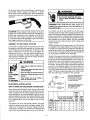
1
IDEALARC® SP-200
SINGLE PHASE, CONSTANT VOLTAGE
DC ARC WELDING POWER SOURCE
‘DAMAGE CLAIMS
When this equipment is shipped, title passes to the pur-
chaser upon receipt by the carrier. Consequently, claims for
material damaged in shipment must be made by the pur-
chaser against the transportation company at the time the
shipment is received. |
This manual covers
equipment which
Is obsolete and no
longer in production
by The Lincoln Electric
| Co. Specifications
and availability of
optional features
may have changed.
SAFETY DEPENDS ON YOU
Lincoln arc welding equipment is designed and built with
safety in mind. However, your overall safety can be increased
by proper installation ... and thoughtful operation on your
part. DO NOT INSTALL, OPERATE OR REPAIR THIS
EQUIPMENT WITHOUT READING THIS OPERAT-
ING MANUAL AND THE ARC WELDING SAFETY
PRECAUTIONS ON THE INSIDE FRONT COVER.
And, most importantly, think before you act and be careful.
ARC WELDING SAFETY PRECAUTIONS
ELECTRIC SHOCK can kill.
. The electrode and work (or ground) circuits are
electrically “hot” when the welder is on. Do not
touch these “hot” parts with your bare skin or wet
clothing. Wear dry, hole-free gloves to insulate
hands.
. In semiautomatic or automatic wire welding, the
electrode, electrode reel, welding head, nozzle or
semiautomatic welding gun are also electrically
“hot”.
Insulate yourself from work and ground using dry
insulation. When welding in damp locations, on
metal framework such as floors, gratings or scaf-
folds, and when in positions such as sitting or lying,
make certain the insulation is large enough to cover
- your full area of physical contact with work and
ground.
. Always be sure the work cable makes a good elec-
trical connection with the metal being welded. The
connection should be as close as possible to the area
being welded.
Ground the work or metal to be welded to a good
electrical (earth) ground.
Maintain the electrode holder, work clamp, weld-
ing cable and weiding machine in good, safe op-
erating condition. Replace damaged insulation.
Never dip the electrode in water for cooling.
Never simultaneously touch electrically “hot” parts
of electrode holders connected to two welders be-
cause voltage between the two can be the total of
the open circuit voltage of both welders.
When working above floor level, protect yourself
from a fall should you get a shock.
Also see Items 4c and 6.
ARC RAYS can burn.
2. а.
Use a shield with the proper filter and cover plates
to protect your eyes from sparks and the rays of
the arc when welding or observing open arc weld-
ing. Headshield and filter lens should conform to
ANSI Z87.1 standards.
Use suitable clothing made from durable flame-
resistant material to protect your skin and that of
your helpers from the arc rays.
Protect other nearby personnel with suitable non-
flammable screening and/or warn them not to
watch the arc nor expose themselves to the arc rays
or to hot spatter or metal.
Oct. °87
WARNING: PROTECT YOURSELF AND OTHERS FROM
POSSIBLE SERIOUS INJURY OR DEATH.
"7 FUMES AND GASES
can be dangerous.
3.a. Welding may produce fumes and gases hazardous
to health. Avoid breathing these fumes and gases.
When welding, keep your head out of the fume.
Use enough ventilation and/or exhaust at the arc
to keep fumes and gases away from the breathing
zone. When welding on galvanized, lead or cad-
mium plated steel and other metals which produce
toxic fumes, even greater care must be taken.
b. Do not weld in locations near chlorinated hydro-
carbon vapors coming from degreasing, cleaning or
spraying operations. The heat and rays of the arc
can react with solvent vapors to form phosgene, a
highly toxic gas, and other irritating products.
c. Shielding gases used for arc welding can displace
air and cause injury or death. Always use enough
ventilation, especially in confined areas, to insure
breathing air is safe.
d. Read and understand the manufacturer’s instruc-
tions for this equipment and the consumables to
be used, including the material safety data sheet
(MSDS) and follow your employer’s safety prac-
tices.
e. Also see item 7b.
WELDING SPARKS can
cause fire or explosion.
. a. Remove fire hazards from the welding area. If this
is not possible, cover them to prevent the welding
sparks from starting a fire. Remember that welding
sparks and hot materials from welding can easily
go through small cracks and openings to adjacent
areas. Have a fire extinguisher readily available,
b. Where compressed gases are to be used at the job
site, special precautions should be used to prevent
hazardous situations. Refer to “Safety in Welding
and Cutting” (ANSI Standard Z49.1) and the op-
erating information for the equipment being used.
с. When not welding, make certain no part of the
electrode circuit is touching the work or ground.
Accidental contact can cause overheating and cre-
ate a fire hazard.
d. Do not heat, cut or weld tanks, drums or containers
until the proper steps have been taken to insure
that such procedures will not cause flammable or
toxic vapors from substances inside. They can
cause an explosion even though they have been
“cleaned.” For information purchase “Recom-
mended Safe Practices for the Preparation for
Er
Welding and Cutting of Containers and Piping
That Have Held Hazardous Substances”, AWS
F4.1-80 from the American Welding Society (see
address below).
Vent hollow castings or containers before heating,
cutting or welding. They may explode.
Sparks and spatter are thrown from the welding
arc. Wear oil free protective garments such as
leather gloves, heavy shirt, cuffless trousers, high
shoes and a cap over your hair. Wear ear plugs
when welding out of position or in confined places.
Always wear safety glasses with side shields when
in a welding area.
Connect the work cable to the work as close to the
welding area as practical. Work cables connected
to the building framework or other locations away
from the welding area increase the possibility of
the welding current passing through lifting chains,
crane cables or other alternate circuits. This can
create fire hazards or overheat lifting chains or ca-
bles until they fail.
Also see item 7c.
CYLINDER may explode
If damaged.
. Use only compressed gas cylinders containing the
correct shielding gas for the process used and prop-
erly operating regulators designed for the gas and
pressure used. All hoses, fittings, etc. should be suit-
able for the application and maintained in good
condition.
. Always keep cylinders in an upright position se-
curely chained to an undercarriage or fixed sup-
port.
Cylinders should be located:
® Away from areas where they may be struck or
subjected to physical damage.
e A safe distance from arc welding or cutting op-
erations and any other source of heat, sparks,
or flame.
. Never allow the electrode, electrode holder, or any
other electrically “hot” parts to touch a cylinder.
Keep your head and face away from the cylinder
valve outlet when opening the cylinder valve.
Valve protection caps should always be in place
and handtight except when the cylinder is in use
or connected for use.
Read and follow the instructions on compressed
gas cylinders, associated equipment, and CGA pub-
lication P-1, “Precautions for Safe Handling of
Compressed Gases in Cylinders,” available from
the Compressed Gas Association, 1235 Jefferson
Davis Highway, Arlington, VA 22202.
FOR ELECTRICALL Y
powered equipment.
6.a. Turn off input power using the disconnect switch
b.
at the fuse box before working on the equipment.
Install equipment in accordance with the National
Electrical Code, all local codes and the manufac-
turer's recommendations.
Ground the equipment in accordance with the Na-
tional Electrical Code and the manufacturer’s rec-
ommendations.
FOR ENGINE
powered equipment.
. Turn the engine off before troubleshooting
and maintenance work unless the mainte-
nance work requires it to be running,
b. Operate engines in open, well-ventilated
areas or vent the engine exhaust fumes out-
doors.
c. Do not add the fuel near an open flame,
welding arc or when the engine is running.
Stop the engine and allow it to cool before
refueling to prevent spilled fuel from va-
porizing on contact with hot engine parts
and igniting. Do not spill fuel when filling
tank. If fuel 1s spilled, wipe it up and do
not start engine until fumes have been elim-
inated.
. Keep all equipment safety guards, covers
and devices in position and in good repair.
Keep hands, hair, clothing and tools away
from V-belts, gears, fans and all other mov-
ing parts when starting, operating or re-
pairing equipment.
e. In some cases it may be necessary to remove
safety guards to perform required mainte-
nance. Remove guards only when necessary
and replace them when the maintenance re-
quiring their removal 1s complete. Always
use the greatest care when working near
moving parts.
f. Do not put your hands near the engine fan.
Do not attempt to override the governor or
idler by pushing on the throttle control rods
while the engine 1s running.
g. To prevent accidentally starting gasoline
engines while turning the engine or welding
generator during maintenance work, dis-
connect the spark plug wires, distributor
cap or magneto wire as appropriate.
h. To avoid scalding, do not remove the ra-
diator pressure cap when the engine is hot.
HAVE ALL INSTALLATION, OPERATION, MAINTENANCE AND REPAIR WORK performed by qualified people.
For more detailed information, it is strongly recommended that you purchase a copy of “Safety in Welding & Cutting —
ANSI Standard Z49.1” from the American Welding Society, P.O. Box 351040, Miami, Florida 33135.
Oct. *87
_w
te
PRODUCT DESCRIPTION
Complete semiautomatic arc welder with constant voltage
transformer/rectifier DC arc welding power source, constant
speed wire feeder and wire reel stand, all in a common
housing. Includes a voltmeter and a 15’ work cable with
work clamp. Also includes one set of drive rolls and guide
tubes for wire size specified. For single phase input power.
Units having an input voltage under 250 volts include a 6’
input cable, plug and receptacle. Units with input voltages
above 250 volts have only a 6’ input cable.
INSTALLATION
ÁN WARNING
HIGH VOLTAGE can kill.
* Do not operate with covers removed.
« Disconnect input power before servic-
ing.
* Do not touch electrically live parts.
MOVING PARTS can injure.
+ Keep away from moving parts.
+ Only qualified personne! should install, use or service this
equipment.
ÁN WARNING e bs ina TE
e Do not lift this machine using lift
| bale if it is equipped with a heavy
accessory such as trailer or gas
FALLING
cylinder.
e Lift only with equipment of
adequate lifting capacity.
e Be sure machine is stable when
lifting.
EQUIPMENT can
cause injury.
- MECHANICAL INSTALLATION
Location — Locate the welder in a dry location where there
is free circulation of ciean air into the louvers in the back
and out the front and bottom. A location that minimizes
the amount of smoke and dirt drawn into the louvers re-
duces the chance of dirt accumulation that can block air
passages and cause overheating. A minimum of 12 inches
of unrestricted space shouid be maintained between the
back of the case or front panels and the nearest obstruction.
WIRE SIZE OR TYPE CONVERSION KITS
The SP-200-AB model comes with the drive roll kit for .023”
thru .035” steel wire factory installed.
The SP-200 welder, as shipped from the factory, does not
have the drive rolls or guide tubes installed. The drive rol!
kit for the electrode size specified on the order is shipped
— with the wire feed unit. The drive roll kit for .035” steel
wire (Which 1s also usable for .023” and .030” steel wire) is
T-15010-.0355, and the drive roll kit for .068” and .072”
Innershield® flux cored wire is T-13355-/2". The drive roll
kit for .062” Innershield flux-cored wire 1s T-13355-Y1¢".
The .068”/.072” drive rolls and guide tubes are marked .068,
5/64 and 3/32" — DO NOT use the equipment for feeding 64
or 3/32" wire. ;
See “Optional Features Installation” for alumınum wire
conversion kits.
Instructions to install the T-15010-.035S and T-13355-%
drive roll kits on new machines, or replace them on used
machines, are as follows:
A. Loosen the idle roll tension screw (item 6) approxi- -
mately 5 full turns or use a screwdriver between the idle
roll arm and the gear box boss at point A to pry the idle
arm out until the idle roll clears the drive roll.
B. Remove hex head screw (item 1) and the drive roll
clamping collar (item 2). {On new machines remove the
tape and drive roll key from the collar.) Insert the key
into the keyway of the output shaft.
C. The .023/.035” drive roll 1s one piece and should be
installed with the required groove up. The wire size
being used can then be read on the top of the roll. The
.068” Innershield drive roll 1s made up of two reversible
drive rolls and a spacer. Wipe the drive roll and spacer
(.068” only) surface clean. Wipe the output shaft and
locating shoulder clean. Install the drive roll on the out-
put shaft. The .068” drive roll is to be installed with the
spacer between the two drive rolls.
D. Install the drive roll clamping collar and hex head screw
previously removed. Tighten hex head screw securely.
E. Back out the two guide tube clamping set screws (item
4). |
F. Insert the outgoing guide (item 3) (the one with the
plastic insert) into the front hole. The guide tube for
‚023 thru .035” wire has a non-symmetrical chisel end.
Be certain the contour with the larger radius and the
exposed oval opening for the wire faces the grooved
drive roll. Push the guide tube back as far as it will go
and tighten the clamping set screw. Insert the incoming
guide tube (item 5) into the rear hole as far as it will
go and tighten the clamping set screw. These set screws
are dog points. When the two tubes are installed prop-
erly these dog points will lock into the annular grooves
that are in each of the guide tubes.
G. Tighten the idle roll tension screw (item 6) or remove
the screwdriver used as a wedge in step A. The tension
screw should normally be tightened until it bottoms and
then backed out two turns for .068” and .072” Inner-
shield wire. For smaller wire sizes and aluminum wire,
the tension screw should be loosened further. The set-
ting depends upon type of wire, surface condition, lu-
brication and hardness. The optimum idle roll setting
can be determined when there are wire stoppages. If the
wire “bird nests” between the drive roll and the guide
tube the idle roll spring pressure is set too high. When
properly set, during a stoppage the drive rolls will slip
and if the electrode 1s removed from the cable there will
be a slight waviness in the electrode for about a foot
beyond the slip marks on the electrode. If there is no
‘waviness the pressure is set too low.
H. To change drive rolls and guide tubes for a different
size, reverse the above procedure.
Ton
POINT (A)? — IDLE ROLL TENSION
ADJUSTING SCREW
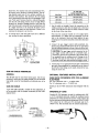
GUN AND CABLE ASSEMBLIES
GENERAL -
The SP-200 may be used with various guns. Use the ap-
propriate Lincoln gun and cable assembly for the electrode
type (solid, cored or Innershield) and electrode size to be
used.
GUN AND CABLE
A gun and cable assembly, suitable for the application, is
to be provided with the proper connectors per the infor-
mation below:
265
—
CONNECTOR MUST BE +
SULATEDIN THIS 252
AREA 1.00 —
- 20 SWITCH REQUIRELENTS
+ 20 125 LG AMP. AC. 24 VOLTS — IHDUCTIVE
AMP. D.C 24 VOLTS — NDUCTIVE
el]
©
S12024-1{L E. PART RC.)
EMOL AROS T-10 OR ECUNALENT
5120208 (LE. PART HG}
AMPHEMOL MS-31069-t8-11P OA EQUNALENT
SP-150 CABLE CONNECTOR FOR 023 - 35 WIRE
. - TO GRY =
«SWITCH ZA |
CORNECT LEADS TO
РЕК САГА СОТ
HOTE — CONMECTOR PART WITH . 7467. TAT DIA
BE MADE FROM BRASS IF IT IS TO BE
"PART OF THE WELDING CURRENT CARRYING
“A” Dia. Hole
To Be Concentric To
Wire Size 749/747 Dia. Within .008 F.I.M.
‚030 & .035 ‚055 (#54 Drill)
.023-.025 .047 (434 Driil)
.045 cored 062 (#3/1s Drill)
1. Lay the cable out straight. Insert the connector on the
welding conductor cable thru the large hole in the front
panel of the SP-200 and into the brass conductor block
on the front of the wire drive.
Note that the connector handle is to be angled down
approximately 15°. Make sure the connector is all the
way in the conductor block and hand tighten the gun
clamping screw securely. Keep this connection clean and
bright.
2. Connect the gun trigger control cable polarized Am-
phenol plug (Amphenol MS-3106-18-11P or equivalent)
into the mating receptacle on front of the wire drive unit.
CAUTION: The gun trigger switch connected to the
gun trigger control cable must be a normally open,
momentary switch. The terminals of the switch must
be insulated from the welding circuit. Damage to the
SP-200 will result if this switch 1s common to any
electrical circuit other than the SP-200 trigger circuit.
3. Connect the 315 I.D. gas hose from the gun to the barbed
gas outlet fitting supplied for installation on the front of
the SP-200. This fitting can be easily removed by loos-
ening the union nut.
OPTIONAL FEATURES INSTALLATION
WIRE DRIVE CONVERSION KITS FOR ALUMINUM
ELECTRODE
For .035” aluminum wire — T-14629-.035A
For 3%” aluminum wire — T-14629-3/0A
Install per the S-17083 instruction sheet shipped with the
kit.
INNERSHIELDS GUNS
Lincoln's K-126 Squirtgun is used for welding with .068”
or .072” Innershield electrode. Install the insulated nozzle
extension (or thread protector) and the nozzle contact tip
for the stickout and electrode size being used. (The T-14050-
.072 contact tip for .068 and .072 electrode and the T-
14050-1/16 for .062 electrode must be ordered separately.) _
For locations where smoke accumulation is a problem and
conventional exhaust systems are ineffective, a K-309
smoke removal type Innershield gun and Linconditioner
vacuum unit can be used. Instructions are shipped with the
equipment.
Tu
(iii
CAUTION: The gun trigger switch connected to the gun
trigger control cable must be an electrically isolated, nor-
mally open, momentary switch. Damage to the SP-200
may result if this switch 1s common to any electrical
circuits other than the SP-200 trigger circuit. All Lincoln
gun trigger switches are of this type.
ASSEMBLY OF GUN CABLE TO SP-200
Lay the cable out straight. Insert the connector on the weld-
ing conductor cable thru the large hole in the front panel
of the SP-200 and into the brass block on the front of the
gear box. Make sure it is all the way in and tighten the
locking screw with a 716” hex Allen wrench. Keep this con-
nection clean and bright. Connect the gun trigger control
cable polarized amphenol plug into the mating receptacle
on front of the wire drive unit.
ÑÁ WARNING
Keep cylinder upright and chained to
support.
Keep cylinder away from areas where it
may be damaged.
GAS « Never lift welder with cylinder attached.
CYLINDERS | + Never allow welding electrode to touch
may тает ‚ a
Keep cylinder away from welding or
explode other live electrical circuits.
if damaged.
ELECTRICAL INSTALLATION
INPUT POWER AND GROUNDING CONNECTIONS
Before starting the installation, check with the local power
company if there is any question about whether your power
supply is adequate for the voltage, amperes, phase and fre-
quency specified on the welder nameplate. Also be sure the
planned installation will meet the National Electrical Code
and local code requirements. This welder may be operated
from a single phase line or from one phase of a two or three
phase line.
The 208/230 volt 60 Hz and 200/220, 380/415 volt 50 Hz
models are shipped connected for the higher voltage. If the
welder is to be operated on the lower voltage it must be
reconnected according to the instructions (S-16962) on the
inside of the removable panel near the rear on the left side.
ÁN WARNING
ELECTRIC SHOCK can kill.
e Do not touch electricaliy live parts
such as output terminals or internal
wiring
WARNING: Make certain that the power cord is un-
plugged before removing the two screws that hold the ac-
cess panel in place.
The 208/230 volt 60 Hz and 200/220 volt 50 Hz models
are shipped with the input cable and plug connected to the
welder. A matching receptacle is supplied with the machine.
Mount the receptacle in a suitable location using the screws
provided. Be sure it can be reached by the plug on the input
cable attached to the welder. Mount with the grounding
terminal at the top to allow the power cable to hang down
without bending.
NOTE: Machines built for power lines over 250 volts are
not equipped with a plug installed on the input cable, nor
a receptacle. The instructions for wiring these machines are
pasted on the inside of the removable panel near the rear
on the left side. Use fuses and input wire sizes suitable for
the input amperes specified on the nameplate.
Using the following instructions have a gualified electrician
connect the receptacle to the input power lines and the sys-
tem ground per the National Electrical Code and any ap-
plicable local codes. See the table for proper wire sizes. For
long runs over 100’, larger copper wires should be used in
the conduit. Fuse the two hot lines with super lag type fuses
as shown in the following diagram. The center contact in
the receptacle is for the grounding connection. A green wire
in the input cable connects this contact to the frame of the
welder. This ensures proper grounding of the welder frame
when the welder plug is inserted into the receptacle.
Connect to a system grounding
wire. See the National Elec-
trical Code and/or local codes
for other details and means
for proper grounding.
Green
Y
Wire
Connect to hot wires of a three-
wire, single phase system or
to one phase of a two or
three phase system.
| Ground-
ing
Wire
Type 75°C Wire in Conduit, Copper se
Input Copper Cond. AWG Size AWG | (Super
Voltage |Hertz| Runs to 100’|Runs over 100'| Size Lag)
200/220 ( 50 8 6 10 80
380/415 | 50 10 8 10 30
OUTPUT CONNECTIONS
A WARNING
ELECTRIC SHOCK can kill.
e Do not touch electrically live parts
such as output terminals or internal
© wiring
WARNING: Turn the welder off before making output
connections.
Connect the electrode cable coming through the case front
from the wire feed section to either the positive (+) or
negative (—) output stud, as determined by the welding
process used. Innershield electrode (.062 and .068 dia.) use
electrode negative polarity and L-50 solid wire (.030/.035”
dia.) and .045 cored OutershieldTM normally uses electrode
positive polarity. Polarity must be correct for the process
used. Connect the 15 foot #2 work cable to the output stud
of the opposite polarity of the electrode cable. Tighten both
nuts with a wrench.
To attach clamp to work cable, insert work cable through
strain relief hole in work clamp and fasten securely with
bolt and nut provided.
AUXILIARY EQUIPMENT CIRCUIT
The power for 115 volt AC auxiliary control equipment such
as a solenoid valve can be obtained from 1/4” quick-connect
terminals located inside the wire feed section. An insulation
flap covers the two terminals. The current draw from this
circuit must not exceed 4 (.25) ampere. The circuit is “hot”
only when the gun trigger circuit is closed.
OPTIONAL FEATURES INSTALLATION
K-162-H 2” O.D. Spindle Kit — To mount the spindle
kit, remove wire feed unit from case. Remove the shaft for
the standard 50-60 pound wire coils from the mounting
framework. Install the spindle per the instructions shipped
with the kit. |
Adjust the brake tension screw (see Operation Sec.) on the
spindle as needed. (2” spindle is factory installed on SP-
200-AB.)
K-363-P 30 Ib Readi-Reel Adapter — Plastic hub for
mounting 22-30 Ib Readi-Reels on a 2” O.D. spindle. (Fac-
tory installed on SP-200-AB.)
K-438 60 Ib Readi-Reel Adapter — Required to feed
50-60 1b Readi-Reel coils from K-162-H Spindle Kits. In-
structions are included with the adapter.
NOTE: Not for use on SP-200-AB.
K-435 Spindle Adapter for 14 Ib Coils — Provides for
mounting 14 16 Innershield® coils on 2” O.D. spindles.
K-340-P Solenoid-Valve Kit — Install per the M-14889
instructions shipped with the kit. (Factory installed on SP-
200-AB.)
K-341 Stitch Timer/Spot Timer/Burnback Kit — In-
stall per the S-16982 instructions shipped with the kit. (Fac-
tory installed on SP-200-AB.)
K-342-25 Foot Wire Feeder Extension Assembly —
Install per the S-16984 instructions shipped with the kit.
K-343-25 and K-343-50, 25 or 50 Foot Power input
Cable with Plug — Install per the M-14253 instructions
shipped with the kit.
K-840 Gas Cylinder Mounting 8: Undercarriage —
Install per the S-18113 instruction sheet shipped with the
kit. |
K-778 Undercarriage — Install per the T-14156 instruc-
tion sheet shipped with the kit.
Wire Drive Conversion Kits for Aluminum Electrode
(Use harder aluminum alioys for better feedability.)
For .035” aluminum wire — T-14629-035A
For #64” aluminum wire — T-14629-¥sA
Install per the S-17083 instruction sheet shipped with the
kit.
OPERATION
WIRE FEED WIRE
CIRCUIT BREAKER SPEED
WELD MODE
VOLTMETER SELECTOR (OPTIONAL)
STIL. WERE SHED
WARMMRG О ITA LT
Cs at
— IDEALARC” SP-2
Le
UN LINCOLN
COARSE ARC FINE ARC POWER
VOLTAGE CONTROL VOLTAGE CONTROL SWITCH
0 ITALIAN TARDE LA ie
TALE VES бло ASÍ FILME
A. Description of Controls
1. Power Switch — Turns machine on and off.
2. Coarse Arc Voltage Control — A five position se-
lector switch which changes the arc voltage by ap-
proximately 4 volts when switched from one
position to the next. (The minimum range 1s for
solid wire only.)
3. Fine Arc Voltage Control — A continuously ad-
justable rheostat that gives approximately 5 volts
of arc voltage control. This control gives overlap-
ping ranges on each of the five coarse voltage con-
trol settings when using solid wire procedures, and
it gives overlapping ranges on each of the upper
four coarse arc voltage control settings when using
Innershield procedures. The Fine Arc Voltage Con-
trol is effective only while welding; it does not con-
trol the open circuit voltage.
4. Voltmeter — This meter reads the voltage at the
output studs of the machine. The actual arc voltage
at the workpiece is slightly lower due to the drop
in the gun conductor cable and in the work cable.
5. Wire Speed — Controls the wire speed from 50 to
400 inches per minute. The control can be preset
on the dial plate to the desired wire speed and the
actual wire speed while welding will be very close
to that value.
6. Wire Feed Circuit Breaker — This control has a
dual function. It can be used as an on-off switch to
completely stop wire feed and it functions as an
overload circuit breaker. When the button is com-
pletely black the circuit breaker is closed and wire
will feed when the gun trigger is pressed. Press the
- button once to turn off the wire feed. A white band
will appear on the button. To turn the wire feed
back on, press the button again. (See Maintenance
Section.)
B. Polarity
Check to see that the cable coming from the conductor
block on the wire feed unit goes to the output stud that
is of the polarity required for the process that is to be
used. (Refer to “Output Connections”, Page 6.)
C. To Start the Welder
Turn the “Power Switch” to “ON”. This lights the red
pilot light next to the switch and starts the cooling fan.
Operate the gun trigger for welder output and to en-
ergize the wire feed motor.
D. Wire Reel Loading (30, 50 and 60 Pound Coils)
1. Open the side door for access to the wire feed com-
partment. To remove the wire reel from its shaft,
grasp the spring loaded knob and pull it out. This
straightens the knob so it seats into the shaft when
released. Remove the reel.
2. Lay the reel flat on the floor, loosen the spinner
nut and remove the cover plate.
3. Before cutting the tie wires, place the coil of elec-
trode on the reel so it unwinds as the reel rotates
clockwise.
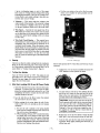
a. Be sure the coil is placed so the spring loaded
arms will not interfere with the later removal of
the coil tie wires. (See photo.)
b. When loading .030 and .035” Lincoln electrode,
be certain the coil is placed on the reel so the
spring loaded arms are at the center of the slots
in the cardboard coil liner. This provides the
positive compression of the coil needed for trou-
ble-free wire feeding. (See photo.)
c. Put the cover plate оп the reel so the four arms
of the cover straddle the spring loaded arms of
the reel proper.
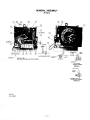
WIRE FEED COMPARTMENT
Shown with optional K-341 Timer Kit and with top of case
removed.
4. Tighten the cover as much as possible by hand. DO
NOT hammer on the spinner nut arms.
5. Cut and remove only the tie wire holding the free
end of the coil. Insert the free end into one of the
holes in the cover and secure it by bending it back.
Cut and remove the remaining tie wires.
CAUTION: Always be sure the free end of the
coil 1s securely held while the tie wires are being
cut and until the wire is feeding through the
drive rolls. Failure to do this will result in “back-
lashing” of the coil, which may tangle the wire,
A tangled coil will not feed so it must either be
untangled or discarded.
. Replace the reel on the wire feeder. Grasp the shaft
knob, pull it out and swing it across the reel hub.
. Turn the reel until the free end of the electrode is
accessible. While tightly holding the electrode, cut
off the bent end.
8. Straighten the first six inches and cut off the first
| inch. Insert the free end through the incoming guide
tube. Press the gun trigger and push the electrode
into the drive roll. Inch the electrode through the
gun. (If the electrode is not properly straightened,
it may not feed or may not go into the outgoing
guide tube causing a “birdnest”.)
A WARNING
ELECTRIC SHOCK can kill.
e Do not touch electricaliy live parts
such as output terminals or internal
ww wiring
WARNING: When inching, the electrode and drive
mechanism are always “hot” to work and ground and re-
main “hot” several seconds after the gun trigger is re-
leased.
E. Wire Reel Brake, 30, 50 and 60 Pound Reel
Mounting
1. The mount for standard 30, 50 and 60 pound elec-
trode coils includes a two position brake assembly.
Generally the brake should be at the inner position
(nearest to the wire reel shaft) for wire feed speeds
below 400 in/min: If excessive wire reel overrun is
encountered, move the brake to the outer position.
2. To adjust the brake position, remove the wire reel.
Pull the cotter pin that holds the brake shoe to the
arm, move the shoe and replace the cotter pin. Do
not bend the cotter pin — 1t is held in place by a
friction fit.
F. Wire Reel Loading — Readi-Reels® and Spools
To mount a 30 Ib Readi-Reel package using the
moided plastic K-363-P type adapter:
1. Rotate the spindle and adapter so the retaining
spring is at the 12 o’clock position.
2. Position the Readi-Reel so that it will rotate in a
clockwise direction when feeding (wire is to be de-
reeled from top of coil).
3. Set one of the Readi-Reel inside cage wires on the
slot in the retaining spring tab.
4, Lower the Readi-Reel to depress the retaining
spring and align the other inside cage wire with the
grooves in the molded adapter. |
5. Slide cage all the way onto the adapter until the
retaining spring “pops up” fully.
To remove the Readi-Reel from Adapter, depress re-
taining spring tab with thumb while pulling the Readi-
Reel cage from the molded adapter with both hands.
Do not remove adapter from spindle.
— 10 -
Á WARNING
ELECTRIC SHOCK can kill.
® Do not touch electrically live parts
such as output terminals or internal
wiring
€
WARNING: Check to be sure the retaining spring has
fully returned to the locking position and has securely
locked the Readi-Reel cage in place. Retaining spring
must rest on the cage not the welding electrode.
MOLDED ADAPTER
2" 0.0. SPINDLE
AETAINING SPRING
READI-REEL
INSIDE CAGE WIRES
THREADED LOCKING COLLAR
To mount a 30 Ib Readi-Reel package using the
formed sheet metal K-363 (obsolete) type
adapters:
1. Remove the locking collar and remove the outside
Readi-Reel adapter arm.
2. Engage the inside Readi-Reel adapter arm in the
brake driving pin and rotate the spindle until the
inside adapter arm 1s in the vertical position.
3. Set the Readi-Reel on the adapter arm. The Readi-
Reel must be installed so that 1t will rotate in a
clockwise direction when feeding (wire is dereeled
from the top of the coil).
4. The outside adapter arm is then to be placed on
the spindle at an angle of 90° from the inside
adapter and the locking collar installed. Tighten the
locking collar securely.
To mount 10 to 30 Ib spools:
1. Remove the locking collar and the Readi-Reel
adapter shipped on the 2 inch dia. spindle. (Readi-
Reel adapter 1$ not required. Use S-18221 Spindle
Adapter for 8” O.D. spools.)
2. Place the spool on the spindle making certain the
brake driving pin enters one of the holes in the back
side of the spool. Be certain the wire comes off the
reel in a clockwise direction when dereeled from
the top of the coil.
3. Replace and tighten the locking collar.
To feed the electrode, turn the Readi-Reel or spool until
the free end of the electrode is accessible. While tightly
holding the electrode, cut off the bent end. Straighten
the first six inches and cut off the first inch. Insert the
free end through the incoming guide tube. Press the gun
trigger and push the electrode into the drive roll. Inch
the electrode through the gun. (If the electrode is not
properly straightened, it may not feed or may not go
into the outgoing guide tube causing a “birdnest”.) Ad-
Just the brake tension with the hex head screw or thumb
screw on the spindle hub, until the reel turns freely but
with little or no overrun when wire feeding is stopped.
Make certain that the wire does not come loose on the
spool or reel when feeding is stopped.
A WARNING
ELECTRIC SHOCK can kill.
e Do not touch electrically live parts
such as output terminals or internal
wiring
wv
WARNING: When inching, the electrode and drive
mechanism are always “hot” to work and ground and re-
main “hot” several seconds after the gun trigger is re-
leased.
G. Wire Reel Changing
1. At the end of a coil, remove the last of the old
electrode by laying the gun and cable out straight
and pulling the electrode end out through the noz-
zle. Load a new reel of electrode per the preceding
instructions.
H. Optional K-341 Stitch Timer/Spot Timer/Burn-
back Kit (Std. on SP-200-AB model)
The optional K-341 Timer Kit consists of a sheet metal
case which contains the timer printed circuit board, four
adjustable controls and a three position mode switch.
The timer kit is installed in the wire feed section of the
SP-200 on the back side of the case front per the in-
struction sheet shipped with the kit. When installed, the
three position “Weld Mode Selector” switch projects
through the SP-200 front nameplate next to the “Wire
Speed” control, allowing easy access to the switch. The
four timer control knobs are located on the timer kit
case panel, which 1s inside the wire feed section above
— the wire feed motor/gearbox assembly. To gain access
to the timer control knobs on the inner panel, open the
door to the wire feed section.
~The three position “Weld Mode Selector” switch is used
to select the following modes of operation:
1. The up position is for the “SPOT” welding mode
which gives single, timed welds. To start the weld,
close and hold the gun trigger switch; the weld will
start and then automatically stop after a timed in-
terval. To produce another timed weld, release and
re-close and hold the gun trigger. The time of the
-11 -
weld is adjustable from '/2 to 3 seconds using the
“SPOTWELD TIME” control on the inner panel.
(Timer dials show increments from 1 to 10. They
are not calibrated in seconds.) Since the timing
starts when the gun trigger is pressed, for consistent
welds it is important that the electrode is either
lightly touching or very near the work when the
trigger is pressed.
2. The center position of the “Weld Mode Selector”
switch is for the “SEAM” welding mode, which is
normal continuous welding. The weld starts when
the gun trigger is closed and stops when the gun
trigger is released.
3. The down position of the “Weld Mode Selector”
switch is for the “STITCH” welding mode. This
mode gives repeated timed welds and time “off”
periods for as long as the gun trigger is held closed.
The “on” and “off” time intervals are independ-
ently adjustable from '/ to 2 seconds using the
“STITCH OFF TIME” and “STITCH ON TIME”
controls located on the inner panel. {Timer dials
show increments from ! to 10. They are not cali-
brated in seconds.) The electrode and auxiliary
power terminals stay energized during the “off”
time; only the wire feed stops. This mode, which
minimizes heat input, is very useful when welding
light gauge sheet metal 18 thru 24 gauge (.048” —
024”), where warpage and/or burn through would
otherwise be a problem. The controls and travel
speed along the seam should be set to give a series
of overlapping welds in which the glow is allowed
to almost disappear from the previous weld before
the next weld begins. Start with the “OFF TIME”
control set at 2 on the dial and the “ON TIME”
control set at about 2.5 on the dial. Re-adjust the
controls as required to give the best results.
The “BURNBACK CONTROL”, which is the top con-
trol on the inner panel, gives an adjustable burnback of
the electrode to prevent it from sticking in the puddle
at the end of a weld. Burnback is accomplished by pro-
viding an adjustable delay of up to !/3 of a second after
the gun trigger is released before the welding power
shuts off. The control should be set at minimum (1 on
the dial) and increased only if the electrode sticks in the
puddle. Increasing the control setting should normally
be required only at wire feed speeds above 250 inches
per minute. The burnback control circuit is effective in
all three modes of operation as follows:
1. In the “SPOT” welding mode, the burnback delay
action automatically occurs at the end of the timed
weld.
2. In the “SEAM” welding mode, the burnback delay
action occurs when the gun trigger is released.
3. In the “STITCH” welding mode, the burnback de-
lay action occurs if the gun trigger is released during
an “ON” cycle.
I. Test Weld
CAUTION: DO NOT turn the coarse voltage
1. Set the “Coarse” voltage selector switch knob to the selector switch while welding since this will
voltage range desired. damage it.
2. Set the “Wire Speed” knob to the speed desired.
8. To stop welding, release the gun trigger and lift the
3. Set up a test plate and attach the work lead to it. gun from the work. The wire feed motor stops and
4. If a Gas Metal Arc process is being used, make any the welding circuit is de-energized after the trigger
other required gas shielding adjustments for the is released. If a solenoid is connected to the aux-
process illary power terminals, it is de-energized when the
trigger is released.
Refer to L-6591, “SP-200 Welding Procedures”, at back
of manual for further instructions.
5. Inch the electrode through the gun and then cut the
end off so that the stickout is approximately 34” for
Innershieid electrode. For .030 or .035” steel wire,
cut the end of the electrode within М4” of the gas
nozzle cone. J. Output Rating
The maximum rated output for the SP-200 and SP-200-
AB, 60 Hz model, is 200 amps, 26 volts at a 60% duty
cycle. Duty cycle 15 based on a 10 minute period.
6. When using open arc processes, it is necessary to
use correct eye, head and body protection.
7. Place the gun into welding position, with the end Therefore, the welder can be operated for 6 minutes out
of the electrode approximately 1/s of an inch above of every 10 minute period without overheating.
the surface of the workpiece and pull the gun trig- — A ,
ger. As the weld is being made, observe the voit- ” For 50 Hz models, rated duty cycle is 50%.
_ meter reading and adjust the “fine” voltage control
knob to the desired value. If it is necessary to
change the “coarse” voltage selector switch, stop
welding before doing so.
MAINTENANCE
B. Welding Power Overload Protection
A WARNING
The SP-200 has a built-in protective thermostat that
ELECTRIC SHOCK can kill. responds to excessive temperature. It opens the input
“|e Do not touch electrically live parts contactor if the machine exceeds the maximum safe
such as output terminals or internal operating temperature because of a frequent overload,
wiring or high room temperature plus overload. The thermo-
stat automatically resets when the temperature reaches
a safe operating level.
WARNING: Have a qualified electrician do the main- . В
tenance and troubleshooting work. Turn the input power C. Wire Feed Circuit Breaker |
off using the disconnect switch at the fuse box before work- ~The circuit breaker to the left of the “Wire Speed” con-
ing inside the machine. Unplug power cable if it is con- |
trol normally trips only when an overload occurs be-
nected to a receptacle.
cause of excessive loading in the wire feed cable, a
defective wire feed motor, or a defective control com-
ponent. The reset button gives a visual indication when
A. General Maintenance the circuit breaker is tripped. After allowing a minute
for cooling, push the reset button. If it trips again, be
sure the wire feed cable is clean and that the cable and
tip are the proper size for the wire diameter being fed.
If it still trips, it may be caused by a defective electrical
component. Pressing the untripped circuit breaker once
turns off the wire feed circuit. Pressing it again turns it
2. The fan motor has sealed ball bearings which re- back on.
quire no service.
1. Whenever routine maintenance is performed on
this machine — or at least yearly — inspect all
nameplates and labels for legibility. Replace those
which are no longer clear. Refer to the parts list for
the replacement item number.
: . , D. Wire Drive Motor and Gear Box
3. In extremely dusty locations, dirt may clog the air © € Motor a ar 50
passages causing the welder to run hot. Blow dirt Every year inspect the gear box and paint the gear teeth
out of the welder at regular intervals. with a moly-disulfide filled grease.
—12-
Every six months check the motor brushes. Replace
them if they are less than !/” long.
Drive Rolls and Guide Tubes
After every coil of wire inspect the drive roll section.
Clean it as necessary. Do not use solvents for cleaning
the idle roll because it may wash the lubricant out of
the bearing. The drive roll and guide tubes are stamped
with the wire sizes they will feed. If a wire size other
than that stamped on the roll is used, the rolls and guide
tubes must be changed.
The drive roll for .068” Innershield and .045 cored Out-
ershield™ has a double set of teeth so they can be re-
versed for additional life. Between the two .068 knurled
rolls 1s a shim washer which limits the damage to the
electrode if wire feeding problems occur. See Mechan-
ical Installation for roll changing instructions.
The drive roll for .023 thru .035” diameter electrode is
a solid roll with two smooth v-grooves; one for .023-
.023” and one for .030-.035”. See Mechanical Installa-
tion for proper mounting for the wire size being used.
Wire Reel Mounting, 30, 50 and 60 Pound Coils
To prolong the life of the wire reel shaft, periodically
coat it with a thin layer of grease. If the brake shoe
wears down to the rivet head, replace the brake shoe
assembly.
G. Gun and Cable Maintenance
I. Gun Cable
— A dirty gun cable can cause rough and erratic wire
feeding; therefore, the cable liner must be cleaned
periodically.
Remove the cable from the wire feeder. Lay it out
straight on the floor. Remove the contact tip from
the gun. Using an air hose and only partial pressure,
gently blow out the cable. Work the full length of
the cable by bending it back and forth and then
blow 1t out again. Repeat this procedure until no
more dirt comes out.
2. Gun Nozzles: K-126 and K-309 Innershield? Squirt-
guns
a. Replace worn contact tips as required. |
b. Remove spatter from tip or extension guide after
each ten minutes of arc time or as required.
c. Replace worn spring liners in nozzles. The life
of the liner can be doubled by rotating liner 180°.
The liner can be pulled out the back end of the
nozzle by wedging the blade of a small screw-
driver in the I.D. and pulling.
d. Internal parts of nozzles can be removed and
replaced by removing the internal hollow-lock
set screw from the contact tip end of the nozzle
with a 532 Allen wrench. The ceramic insert and
retainer will normally fall out the end of the
nozzle but if they do not, gently drive the spring
—13-
liner towards the outgoing end of the nozzle.
When re-assembling nozzle, make certain the ce-
ramic nozzle insert is placed next to the spring
liner. The hollow-lock set screw is to be tight-
ened to give the dimension of .38 as measured
from the end of the nozzle to the hollow-lock
set screw.
3. Gun Disassembly: K-126 and K-309 Innershield
Squirtguns
a. To remove the nozzle from the gun, loosen {do
not remove) the !/4-20 socket head screw with a
% Allen wrench in the gun handle and pull the
nozzle straight out. To reinstall, insert the nozzle
into the gun handle. Push it in as far as possible
and tighten the Allen head screw.
b. To disassemble Innershield Squirtguns, first
loosen the screws which hold the heat shield in
place. Remove the heat shield.
¢. To disassemble the switch housing from all these
guns, remove the four screws holding the saddle
around the gun handle.
d. Then hold the housing with the cable toward the
floor and look into the switch cavity. The tight
side of the larger roll pins is to the right. Drive
these pins to the left. They can be easily removed
when they clear the right side of the casting.
e. Do not remove the smaller roll pins unless the
trigger is being replaced. The height of the Z
spring controls the operating point of the switch
with respect to the trigger movement. Set the
spring so the switch operates at about the mid-
point of the trigger travel.
f. To remove the handle from the cable, slip the
spatter shield out of the front of the handle.
Loosen the 4-20 socket head screw in the side
of the handle. Remove the snap ring. The handle
and connection clamp can then be slipped off
the cable.
. For K-426-.045 GMA Gun Cable Maintenance re-
fer to manual supplied with gun.
TROUBLESHOOTING
Á WARNING
“Y
ELECTRIC SHOCK can Kill.
e Do not touch electrically live parts
such as output terminals or internal
wiring
WARNING: Disconnect input power before servicing.
Only qualified personnel should install, use or service this
equipment.
PROBLEM POSSIBLE CAUSE WHAT TO DO
I. Rough wire feeding or wire not feeding | a. Gun cable kinked and/or twisted. a. Inspect gun cable and replace if
but drive rolls turning. necessary.
b. Wire jammed in gun and cable. b. Remove wire from gun and cable —
feed in new wire. Note any obstructions
in gun and cable. Replace gun and cable
if necessary.
c. Incorrect drive rolls and guide tubes. c. Check wire diameters stamped on drive
rolls, wire guides and drive roll spacers
for correct combination for wire being
used. |
d. Drive rolls loose. d. Remove, clean, install and tighten.
e. Gun cable dirty. e. Ciean per Sec. G.
f. Worn drive rolls. f. Replace and/or reverse split drive roll
type.
g. Electrode rusty and/or dirty. g. Replace.
h. Worn nozzle liner. h. Replace.
J. Partially flashed or melted contact tip. |). Replace contact tip.
2. Variable or “hunting” arc. a. Worn and/or melted contact tip. a. Replace tip — remove any spatter on
end of tip.
b. Worn or undersized work cable or poor | b. Inspect — repair or replace as
work connection. necessary.
c. Loose electrode connections. c. Be sure electrode lead is tight, gun cable
tight in wire feeder contact block, gun
nozzle and gun tip tight.
3. Weld porosity, narrow and ropey bead, | a. Dirty plate or improper procedures. a. See troubleshooting information in
or electrode stubbing into plate when Bulletin N675, “Innershield Production
welding. Welding Guide” or Bulletin N677,
| “Innershield NR-211 Welding Guide”.
4, Wire feed circuit breaker trips while a. See Trouble 1 above. a. Correct problem.
welding.
b. Defective wire feed motor or gearbox. b. Replace.
5. No wire feed or no control of wire feed. | a. Wire feed circuit breaker in “off” a. Re-set circuit breaker.
Contactor pulls in and voltmeter position.
indicates voltage.
b. Electrical component such as control b. Replace.
printed circuit board has failed. Blown
10 amp fuse on control P.C. board
indicates that the control P.C. board
has probably failed.
6. No wire feed and no output voitage. a. The 4-prong connector going to the wire | a. Correct problem.
Pilot light indicates input power to feed unit or the optional extension
SP-200. cable may not be making contact. -
b. If Timer Kit is not installed, jumper b. Make certain jumper plug is in place.
plug may not be properly seated 1n six (See K-341 Timer Kit installation
cavity connector. instruction page.)
c. Faulty gun trigger switch or damaged ¢. Repair,
control cable connected to gun trigger.
d. Gun trigger circuit not electrically d. If the gun trigger switch or control cable
isolated. is in any way common to any electrical
circuit other the the SP-200-24V trigger
circuit, damage to the SP-200 can
result.
e. Input power contactor has failed. e. Replace.
f. Timer Kit may be defective. f. See Problem 8.
- 14 -
PROBLEM
POSSIBLE CAUSE
WHAT TO DO
7. Wire feed control but output voltage
continuously present with gun trigger
off.
. Input power contactor has failed.
. Gun trigger circuit not electrically
isolated.
. Timer Kit may be defective.
. Replace.
. If the gun trigger switch or control cable
is in any way common to any electrical
circuit other than the SP-200-24V
trigger circuit, damage to the SP-200
can result.
. See Problem 8.
8. Suspected defective Timer Kit.
. Improperly set machine.
. Connector plugs not making contact.
. Defective Timer.
. Check position of “Weld Mode
Selector” switch. Be certain that it is set
for the mode desired.
. Make certain that the plugs connecting
to the Timer P.C. Board are properly
seated. Check operation of machine.
. Remove Timer Kit (see K-341
installation instruction page) and install
jumper plug which is stored at bottom
of Timer Kit case. Check operation of
machine. If problem is corrected, Timer
Kit is defective. Replace.
9. Poor welding characteristics and/or
cannot obtain full rated output of 200
amps at 26 volts.
. Capacitor(s) in power source output
circuit failed. À failure is indicated if
the small vent plug on top of a
capacitor is raised or blown out,
. Replace entire bank of capacitors. Do
not replace individual capacitors.
WARNING: The Liquid electrolyte in
these capacitors is toxic. Avoid contact
with any portion of your body. Clean up
vented electrolyte using rubber gloves,
and a water dampened cloth. Any
electrolyte which gets on skin, clean
with soap and water.
— 15.
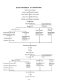
'SP-200 SEQUENCE OF OPERATIONS
Input power lines energized
Primary of control transformer energized
Power ‘“ON-OFF”’ switch to ‘“ON”’’ position
Closes 31 to 531 ad 300 to 304 circuits
Pilot light, fan, and control circuits energized
|
Press gun trigger
Closes 302 to 303 circuit Energizes Stitch Timer/
| Electrode is “hot” to work
|
> Spot Timer/Burnback Kit
Energizes ICR If connected
|
1
Closes 531 to 7 circuit a Opens 207 to
| Closes 207 circuit 541 circuit
|
Energizes line contactor 2CR 115V AC present Energizes control Remove dynamic
| | at 7-32A circuit and wire brake from wire
Energizes primary of welding | feed motor armature feed motor
transformer . e
| Energizes auxiliary
| equipment if
Voltmeter reads OCV connected to 7-32 A
(gas solenoid)
Wire feed motor starts (feed wire)
E
Opens 531 to 7 circuit
i
De-energizes line contactor 2CR
De-energizes welding transformer
Voltmeter decays to zero
Electrode “cold” to ground
Arc starts
|
Welding
Release gun trigger
Opens 302 to 303 circuit De-energizes Stitch Timer/
| Spot Timer/Burnback Kit
De-energizes ICR ifused
[ Closes 207 to
| Opens 207 circuit 5 41 circuit
De-energizes De-energizes control Apply dynamic
auxiliary circuit and wire brake circuit
equipment feed motor armature to motor
connected
to 7-32A
|
Wire feed motor stops
|
Arc stops
Unit ready for next weld
- 16 -
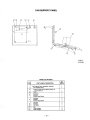
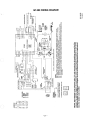
GENERAL ASSEMBLY
(P-139-C)
SEE SKETCH 2
SEE SKETCH
“ab o
apres | TR
В . y | POE a = AAA x т Е TE. =
TRANSFORMER
(19) (8) VEAP WASHER.
FLEX LEAD
- RECTIFIER MOUNTING DETAIL CABLE TIE
FAN SUPPORT ENDS
5 L
SEE DETAIL TEST PER E-2505. PANEL SKETCH 3
SEE RECORDS FOR. LEADS, LEAD MTG'S. & SLEEVING. ===
BRASS HUT
HIGH VOLTAGE
TERMINAL MOUNTING
SKETCH |
FLEX LEAD
PLAN
WASHER
- TRANSEORMER, LEAD
SELECTOR, SWITCH MOUNTING
SKETCH 2
L-6574
—10-15-82F
-17 -
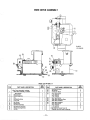
Parts List P-139-C.1
ITEM
PART NAME & DESCRIPTION
NO.
REQ'D
Center Panel Assembly, Includes:
Mag-Amp Assembly
Lift Bail
Lift Bail Seal
Fan Support Panel Assembly See P-139-D
de wre milo anil
ei MN
Front Panel Assembly See P-139-E
Choke Coil
Selector Switch
Selector Switch Handle
Handle Screw
Capacitor Assembly, includes:
Capacitors
Capacitor Jumper
Capacitor Mounting Bracket
Capacitor Insulation
Base & Transformer Assembly, | includes:
(Specify Single or Dual Voltage)
— — | PI] eh mh | wk eh
11
Base
Transformer Assembly (Specify voltage)
Reconnect Panel Assembly 139-G
— rt
12
14
Case Back
Splash Shield Assembly
Case Door & Hinge Assembly
ты wand, md
15
17
Wire Feed Unit See P-139-H
Electrode Lead
Thermostat
18
21
Cable Hanger
Grommet Strip
Rectifier Assembly, includes:
Positive Diode
Negative Diode
Suppressor Assembly
Rectifier Mtg. Bracket
Items Not Illustrated:
| = NN | + | dach ak
Left Case Side
Access Door (Left Case Side)
Roof
Ground Clamp
Ground Cable
Door Strike
Lincoln Decal (Mounts on Door)
Drive Roll & Guide Tube Kits See P-139-J
Auxiliary Transformer
wd — == = ndo vero ia
Timer By-Pass Jumper Plug
SP-200 Procedure Sheet — Mounts Inside
Case Door
Optional Equipment:
10 to 25 Pound Spool Spindle Kit
Gas Solenoid Kit [Standard On
(-AB) Models]
Timer Kit [Standard On (-AB) Models]
See P-139-F
25 Foot Wire Drive Extension Cable
25 Or 50 Foot Input Cables & Receptacle
See P-139-G
Undercarriage (Without Gas Cylinder Rack}
==
Undercarriage (With Gas Cylinder Rack)
- 18 —
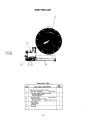
FAN SUPPORT PANEL
Parts List P-139-D
NO..
ITEM PART NAME £ DESCRIPTION REQ'D
Fan Support Panel Assembly, Includes: 1
1 Fan Support Panel 1
2 Control Printed Circuit Board (Does not
include item 3) 1
3 Relay 1
4 Grommet 1
5 Resistor 1
Round Head Screw 1
Insulator 2
6 Resistor 1
Round Head Screw 1
Insulator 2
8 Resistor 1
9 Fan Motor 1
10 Fan 1
11 Cable Hanger 3
Cable Hanger 2
12
.. 19—
L-6459
6-29-84]
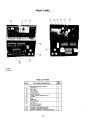
FRONT PANEL
L-6460
3-15-85T
Parts List P-139-E
| NO.
ITEM PART NAME & DESCRIPTION | REQ'D
Front Panel Assembly, Includes: 1
1 Front Panel 1
2 Pilot Light 1
3 Power Switch 1
5 Circuit Breaker 1
6 Voltage Rheostat 1
8 Output Terminal Replacement Kit 2
10 Voltmeter 1
11 Knob 2
12 Nameplate 1
14 Warning Decal 1
15 Grommet 1
17 Wire Feed Rheostat 1
Rheostat insulation 1
18 Plug Button (Std. Machines Only) 1
19 Solenoid {(— AB Machines Only) 1
20 Solenoid Nameplate (— AB Machines Only) 1
— 20 —
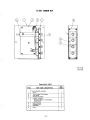
K-341 TIMER KIT
um ms —
M-14139
10-2-81B
Parts List P-139-F
NO.
ITEM PART NAME & DESCRIPTION REQ'D
Timer Assembly, Includes: 1
1 Panel 1
2 Timer Printed Circuit Board 1
3 Inner Panel 1
4 Rheostat Insulation 4
5 Harness, Includes: 1
Rheostats (RS, R11, R22 & R23) 4
Mode Switch 1
6 Switch Bracket 1
7 Expansion Nut 4
8 Nameplate 1
9 Knob 4
-21 -
M-14109
5-10-85K
RECONNECT PANEL
Parts List P-139-G
ITEM
PART NAME & DESCRIPTION
NO.
REC'D
Reconnect Pane! Assembly, Includes:
Terminal Bushing
Mounting Panel Assembly
Contactor
Reconnect Panel
| GO MWN | —
Conduit Clip
Grommet |
Input Cable (6 Ft.) (Standard)
= = | o | Ne
10
Above 250V input Only
Input Cable (6 Ft.)
(Standard) Below 250V
Input Cable (25 Ft.)
(Optional) Below 250V
Input Cable (50 Ft.) (Optional)
12
input Only
Insulation
— le
Items Not lliustrated:
Power input Receptacle
(Below 250V input Only)
-22-
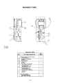
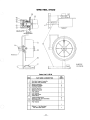
WIRE DRIVE ASSEMBLY
SET
L-6422
12-19-85G
Parts List P-139-J.1
NO. NO.
ITEM PART NAME & DESCRIPTION REQ'D | [ITEM PART NAME & DESCRIPTION REG'D
18 {dle Roll Pull Arm 1
Wire Drive Assembly, includes: 1 20 Set Screw 2
1 Gear Box Assembly, Includes: 1 22 Conductor Block i
Drive Motor 1 25 Hex Head Screw 2
2 Sems Screw 1 Lock Washer 2
3 Collar Assembly 1 Plain Washer 2
6 Key 1 26 Hex Head Screw 1
9 Locator Bushing 1 28 Gear Box Mounting Plate 1
10 Cord Clip 1 29 Gear Box Insulation 1
11 Set Screw 1 30 Gear Box Insulation 1
12 Groove Pin 1 31 Hex Head Screw 2
13 Idle Roll Assembly 1 Plain Washer 2
14 Idle Roll Arm Bracket 1 Lock Washer 2
15 Thread Cutting Screw 1 Drive Roll and Guide Tube Kit 1
16 Spring 1 (Specify wire size when ordering)
-23
M-14165
3-23-84M
WIRE FEED UNIT
Parts List P-139-H
NO.
ITEM PART NAME & DESCRIPTION REQ'D
Wire Feed Unit Assembly, Includes: 1
1 Wire Drive Assembiy See P-139-J
2 Gear Box Support Platform, includes: 1
Amphenol Receptacle 1
4 Pin Receptacle 1
3 Wire Reel Stand See P-125-N
3 Wire Reel Support, Includes: 1
Wire Reel Shaft See P-107-P Col. 3
5 Plug Retainer 1
Thumb Screw 1
7 Wire Reel 1
8 Grommet 1
— 24 ~
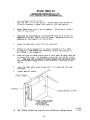
WIRE REEL STAND
: N A Je]
dl 1257 Le
FOR BEST RESULTS...
|
WIRE REEL SUPPORT e
DETAIL A
CIDP NIEW- FULL. SCALE 7
NA, N
Ne
. SEE DETAL A —
L-6832-P
12-19-85G
= ор о = ——
Parts List P-125-N
NO.
ITEM PART NAME & DESCRIPTION REQ'D
Wire Reel Support Assembly
Wire Reel Shaft Assembly
Spindle Assembly
Readi-Reel Adapter
Insulating Washer
Insulator Bushing
Brake Disc Spacer
Piain Washer
Lock Washer
Hex Head Screw
Cable Clamp
Thread Cutting Screw
12 Retaining Collar (Not lllustrated)
13 Readi-Reel Decal
14 Plain Washer
QO ON СО ЛО | N=
nme
Optional — Not Illustrated
10% Wire Reel Spacer _ 1
= 25 —
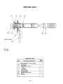
WIRE REEL SHAFT
oN Na WN DAS
a
—
shim ia
AM
-.
NN ——<UN:
И
1 |
SUPPORT —
M-12460
10-28-83L
Parts List P-107-P
ITEM
PART NAME & DESCRIPTION
NO.
REQ’'D
Reel Mounting Shaft Assembly, Includes:
Hex Head Bolt
+ D
Lock Washer
Brake Assembly, includes:
Brake
Cotter Pin
Plain Washer
Insulator Bushing
DO NO
Insulating Washer
Wire Reel Shaft Assembly
Roll Pin
Pull Knob
ill wel ey ade —— ll. — cl == =
- 26 —
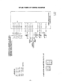
SP-200 WIRING DIAGRAM
CITS-C-L
6POP I-W
| ‘lJgqunu spo9 19P/9M 3U) SAI5)
JUOUdIE|d91 E 104 JUOWPEd9 QG 9I1A19S OU) 01 9111M ‘ojgiBDolt SI WEJDEIP O4) 1] *SjoUEd sINSOJOUS
94) JO sUO LO OUIYIEW 34) opisur pajsed si apoo vejnarued e 10} шелбетр 9119ads ayy “jenuew
514} Ад рэлэлод 5вэшцоеш [|B 10} эуелпоэе JOU SI y “ÁJuo 39348349j34 10) SI WUBJDEIP SIUL :3.LON
LB ©
va?
1 2 ¢€
"Sans Tano
SUL LV SOVITARL 3541007 140 00749 SMA MANI ALCAVWS ML ЗЭМУНо UL. IMLISOG. ALIAVIOS 2004153173. 3H «Моно WWUSVIT SAL "EN
wi an 9 > 8330 За 1500 Navy Naum “ON ALIADA e
SNOILYIidd Y 220408 ONY ELVIGIvIaI 39 TITAD ALOE QNY im DHL 393 ALVY ads Bd IL 40 39 15 9 aM GQ (AVE Da 20 IAC INandAWO>)
SENA TOONI SEVA 219NIS NO LNYSIUI LON TENYI IIINNOJIN STE ным
"OBEN! SS} LI NAHM dEanvidg Si Mamo) Cidade 31>v143339 LN OVINO] wanda -USNIL Ivi WNÁILO AININGIS ONIEEWON ALIAYI
“SNILYS dWY 570 "DY AGN LNÍVMEINDS ALMINZOY LI3NNOJ OL ZE L SANIWDAL LINNO0 WO "EN =
SS ILON 2400
ANAL \а
TWNOLLWN ¥3d
AWOOHD QL
"AN ALIAY) YOLDENNOS SSLWDIONT 5¢
ON
"AN
LEST-S d3d SICUWAS ЛУ НВА СОМ
“НОТА YAIWUDISNYUL YIMÓd
OL
MO
Зоо)
ЗЧ МНО
от
ino — c
BOVLIOA 3ÉWWOI
ti = Ш
92
102
UOLIVANDD
10d
nani
309819373
| 65
HI ANY M HOION
go [ A 52 4 5352 EM
| ad a im
OBIWOS \ pi ST 339951,
y ESVINOR ING © 0034< < 0 —vIV NAS OL
gré <! K <+y
Po ns To <+— 8
LYLSONNIHL Æ— D
2
~ 27 —
ae — oc Ñ 19€ SLIT - M |
"059 SYR aWY DY - ‘A tal
| QU Ia IYLNOI TE + €+-0 RS x po DEl
- — ds = ‘MOOV T0Z LA
КОЛОС «МЧ А VO! ta) О ох ЧаВо -5
les | | a = ` A va 94
ère + 3905 20105 ‘MZ VOS 4%
ыЭмо | MOS OZ bY
re 'MOS AZ Ca
£ >> 012- HSWHOSSNYHL НАМ) +
2 >> ee GA NING III TOW vo va mam 1a
- —_ pe ro GE 02 IÍ7MOLL TI
7L9' AD
AREA
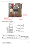
SP-200 TIMER KIT
INSTALLATION INSTRUCTIONS FOR K-341
ST) TER TIRER/SPOT MELD_TINERBURNAACI- KIT
aio —
| Turn the 'Power Switch'' to "CFF",
Open side door to wire feed section. Observe jumper plug attached to
six cavity connector in upper front corner of wire feed section.
2. Detach Jumper plug from six cavity connector. Store plug on inside of
timer kit case bottom.
3. Remove hex nut and lockwasher from the #10-2L screw going through the
nameplate on the door side of the front panel. Remove hole plug from
nameplate at ''Spot-Sseam-Stitch'' switch hole.
Ц. Remove the sheet metal screw from inner case panel.
5, Connect six cavity connector to six cavity receptacle on P.C. Board
of Timer Kit. When making this connection, be sure the connector Is
well seated in the receptacles.
6. Place the Timer Kit pane! against back of front panel as shown below and
re-insert 10-24 screw. Put lockwasher on and start-nut (do not tighten
yet). Make sure that no leads are pinched between the sheet metal parts,
“and that the small toggle switch is thru the hole in the front of the
- machine.
7. Insert the sheet metal screw through slot in kit panel and into inner
В
8. Tighten down all screws.
a
>
Je
FRONT PANEL
KMU KIT ——
SHEET METAL SCREW
LM
* 10-24 x .375 SCREW
LOCK WASHER
и. & 10-24 HEX. NUT
9 SEE SP-200 OPERATING MANUAL FOR OPERATING INSTRUCTIONS.
— 28 -
S-16982
5-14-82V
CS FLAF
SP-209 VA
CASE — > E -
FRONT DNA — mm
|
|
|
INLET (IN) PORT To
BE POINTING UP
* 10D *.75 SELF TAPPING
ss
#15-ZA x .50 THREAD
CUTTING MACHINE Tag
SCEEW
CSTAR” LOCKWASHER — |
СКО ЮКОС LEAS
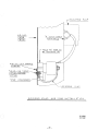
SOLENOID VALVE AND LEAD INSTALLATION
ST M-14889
A 8-27-84C
— 29 -
SP-200 TIMER KIT WIRING DIAGRAM
18-0€-1
6v0L1-S
— o] —— NA —
‘За ММ
HOLILS $ AIAM Lods
L <
EG <
vo +H—<
Yee <
COS +
L 866]
v 49 № 4 9
| Ze | 2 ¢
NANA
SM RLIAYI) HOLIANOS ALI ANT%A
HOUNS BA0W - 1 MS
MZ Aool -EZA
"MZ: 7001 =2 4
MZ - 1400| » UY
MZ: 4001 - 48
“aAnNaga1
L\ DNINISN\ A30A39_
GIAOW33 39 1SQW IMA VAAWAP
=
— 30 —
SP-200 DIMENSION PRINT
La
+ | |
@ | 1 Tit 250/250 D
{1 —
LL. HÍ
|! J
| | А
I
| EA
I 1 I
CT EAN
I | i a
E E ee t 1
г === —= 1 == — |
4 а
Ë LL i
- \
APPEMES ON TG _250/250 € SP-200 WITH GAS CYLINDER SUPPORT ONLY.
G
la--———— 12.12 - 26.00 =
27,51
5.00 DIA WHEEL |
10.00 DIR WHEEL o 515
28.25 —
L-6480
3-8-85C
- 31 -
-32-
- 33 ~
- 34 -
oat). INNERSHIELD® AND WIRE WELDING WITH YOUR SP-200 “E.
This chart is a ready reference for using the Idealarc® SP-200. Refer to Lincoln bulletins and instruction manuais for details. Be sure to read
and understand the section on ARC WELDING SAFETY PRECAUTIONS,
Because design, fabrication, assembly and welding variables affect the results obtained in applying this type of information,
the serviceability of a product or assembly is the responsibility of the builder/user.
INNERSHIELD WELDING
Suggested settings. Adjustments may have to be made to achieve optimum results under various
conditions. See "Welding Procedures” and “Problem Solving” sections of N675 and N677.
“AUTO STITCH” AND “AUTO SPOT” WELDING
Suggested settings. Adjustments may have to be made to achieve optimum results under various
conditions. Also read section below on “MIG Welding”.
INNERSHIELD WELDING
This process utilizes an easy-to-use self-shielded flux cored electrode. It is important to
understand some of the special characteristics of Innershield electrodes and your
SP-200. Refer to Lincoln booklets N675 and N677 and the Operating Manual (IM-312)
for details.
Only .068” diameter Innershield electrodes can be used with the SP-200. Be sure the
drives rolls and guide tubes are marked .068”. Connect the wire feeder output leads for
electrode negative. Be sure to properly load the wire reel. Use the K-126 gun and thread
protector. The insulated guide supplied with the K-126 gun should not be used with .068
electrode. Choose the proper electrode and start by using the settings shown above.
Maintaining the proper electrical stickout (the distance from the end of the contact tip to
the weld puddle) is very important.
ELECTRICAL STICKOUT — Good weld quality requires using the electrical stickout
specified. Electrical stickout is the distance from the end of the actual contact tip to the
end of the electrode. |
STARTING THE ARC — With the proper electrical stickout set, position the gun with
the wire lightly touching the work. Press the gun trigger to start the weld.
Some weldors accustomed to stick electrode welding tend to push the gun into the
joint as the wire burns away. Since the wire is mechanically fed, this is not necessary.
Remember, it is very important to maintain the proper electrical stickout at all times.
To stop the arc, release the trigger and pull the gun from the work.
SETTING VOLTAGE — Adjust voltage with the controls on the power source. Read the
voltage on the power source voltmeter while the arc is lit.
SETTING WIRE SPEED (CURRENT) — Adjust the wire speed using the control on the
wire feeder. Recommended wire speeds are given in the procedures.
TRAVEL SPEED — Move the gun along the joint at a travel speed which keeps the arc
just at the front edge of the weld puddle and produces the desired weld size. Always
maintain a uniform travel speed.
DRAG ANGLE — Tilt the gun in the direction of travel about the same as required in
stick electrode welding. If slag tends to run ahead of the arc, increase the drag angle
slightly.
ELECTRODE ANGLE TO JOINT — Point the electrode into the joint. The wire angleto
the joint should be about 45° for fillet welds.
MIG WELDING
THE SP-200 IS AN EXCELLENT MACHINE FOR MIG WELDING WITH MILD
STEEL, STAINLESS STEEL, ALUMINUM, OR BRONZE (FOR GALVANIZED
STEEL) FILLER WIRE, AS WELL AS FOR AUTO STITCH AND AUTO SPOT
WELDING. THE MACHINE SETTING GUIDELINES SUPPLIED ABOVE SHOULD
BE SUPPLEMENTED WITH APPROPRIATE MIG WELDING INFORMATION TO
ENSURE THE CORRECT USE OF EQUIPMENT AND PROCEDURES. THE
LINCOLN ELECTRIC COMPANY DOES NOT SUPPLY PROCEDURES FOR ANY
OF THE MIG PROCESSES.
Volts Approx. Wire Volts
Electrode Size, Material | Wire Speed | Elec. Neg. | Current | Coarse Voltage | Fine Voltage Size Material | Wire Speed | Elec. Pos. | Coarse Voltage | Fine Voltage Spot Time for
Type, & Stickout Application Thickness in/min DC(-) Amps Setting Setting & Type, Thickness in/min DC(+) Setting Setting Stitch On Time | Stitch Off Time | Plug Spot Welds
.068 NR-211 ; 18 Ga (.048) 150 17 14 — 19 2.5 2.5 2 4
sn " , single or multiple 12 ga and | —_
76 to Ju” Electrical pass, mild steel thicker 75 18 190 14 — 19 4.5 030 |20 Ga (.036) 125 16 Min — 16 7 2.5 2 5
: - L-50 |22 Ga (.030) 110 16 Min — 16 5.0 2.5 2 5
single pass, 16 ga 50 15 165 14 — 19 24 G > 00 ; 45 2.5 2 5
.068 NR-152 uncoated or 14 ga 60 16 195 14 — 19 3 4 5a (024) L o Mm — 16 - -
Y," Electrical galvanized mild 72 3 18 Са (.048) 125 17 14 — 19 2.5 2.5 2 4
i steel up to 4." ga an ‚035
Stickout max. one, 10 ga 0 "7. 220 14 — 19 3.5 so |20 Ga (036) 110 16 14 —19 1.5 2.5 2 5
22 Ga (.030) 100 16 Min — 16 7 2.5 2 5
BURNBACK CONTROL
This control sets the time the arc is on after wire feed stops. Increase time only if welding
wire sticks to the end of the weld.
STITCH TIMER
(“AUTO STITCH”)
Used to weld thin material where warpage and burnthrough are a problem. Proper
adjustment of ON and OFF times and arc travel speed permits welding 18 through 24
gage (.048" — .024") sheet metal with small welds, minimum distortion, and no burn-
through.
To weld, set “WELD MODE SELECTOR” to “STITCH” and the other controls per the
above table. Close trigger and hold it closed for length of seam. Hold gun in one place
during ON time and move gun just beyond edge of molten metal during OFF time.
“STITCH ON TIME” control — sets welding time. Raise setting to increase penetration |
and weld size; lower to reduce burnthrough and distortion,
“STITCH OFF TIME” control — sets off time. Raise setting to reduce burnthrough;
lower to make weld flatter and smoother,
NOTE: For smoothest welds on thinner metal, point gun slightly towards direction of
travel.
SPOTWELD TIMER
(“AUTO SPOT”)
Arc spot plug welds are used when continuous welds are not needed or to hold thin
sheet metal together prior to Auto Stitch Welding or continuous welding. Plug welds are
made by punching a %¢ inch hole in the top sheet and arc welding through the hole into
the back sheet.
To make an arc spot plug weld, punch %,g holes in top sheet. Set “WELD MODE SELEC-
TOR" to “SPOT” and the other controls per the above table. Install spot weld nozzle (if
available) on gun and press it against the top sheet so the top and bottom sheets are
tight together. Close trigger and hold it closed till the arc goes out. If aspot weld nozzle
is not used, smoother welds will result by moving the welding wire in a small circle
during the weld. |
“SPOTWELD TIME” controi — sets welding time. Higher settings increase penetration,
diameter, and height of weld.
THE LINCOLN ELECTRIC COMPANY — CLEVELAND, OHIO U.S.A.
METAL SHRINKING
The SP-200 can be used with a carbon rod to produce localized heating and, when
combined with water quenching, can remove small dents and distortion in sheet metal.
For Metal Shrinking set “WELD MODE SELECTOR" to “SEAM” and “COARSE” and
“FINE” arc voltage controls to lowest setting. Press “WIRE FEED CIRCUIT BREAKER”
to turn wire feed off. Connect output leads for electrode positive. Attach a carbon rod to
the welding gun using a special attachment or use a separate eiectrode lead and stick
electrode holder with a carbon rod. Place the pointed end of the carbon rod (do not use
copper coated carbon rods) firmly against the sheet metal in the distorted area. Close
the gun trigger and move the rod in a circular motion keeping in contact with work.
When distortion is reduced, release trigger, remove carbon, and immediately quench
area with a water-soaked rag. Repeat if required. To prevent arcing, carbon must be
firmly against sheet metal whenever trigger is closed or opened.
METAL FILL
This procedure is used to fill gaps, holes and distorted areas in sheet metal.
NOTE: This procedure should not be used where weld strength is required.
To Metal Fill on steel sheet metal, set “WELD MODE SELECTOR" to "SEAM”, plus
“COARSE” and “FINE” voltage controis to lowest settings. Set “WIRE SPEED" to 300
in/min for .035 wire and 375 in/min for .030 wire. Connect wire feeder output leads for
electrode postive. An arc welding shield with a #8 filter must be used 10 protect the eyes
from heat and brightness. Start with the wire sticking out about 1” beyond the gun tip
and the wire lightly touching the sheet metal. Close the trigger and slowly weave the
gun back and forth over the area to be filied. If there is arcing and flashing, increase the
“WIRE SPEED” and/or decrease the wire stickout. If the wire pushes the gun back,
decrease the "WIRE SPEED” and/or increase the wire stickout. After filling, set the
“WELD MODE SELECTOR” for “STITCH” or “SEAM” and arc weld the fill metal to the
base metal.
PROCEDURE TO INSTALL DRIVE ROLL AND GUIDE TUBES
. Turn off power. 7. With tubes properly seated, tighten set
4
2. Remove hex screw and clamping collar from screws.
drive shaft with 2” wrench. Loosen idle roll. 8. Tighten idle roll pressure screw and back out
3. Install key and drive roll. Doubte grooved 2 turns for larger wires, For aluminum and
drive rolt for .023"-.035" to be installed with .023"-.052" steel wire screw must be backed
side stenciled for correct wire size facing out out to prevent buckling with wire stoppage
and with slotted spacer on top of roll. Two (see Operating Manual).
piece drive rolls for .068" have spacer be- 9, To start new electrode, straighten the first
tween rolls. Replace collar and tighten hex 6” and cut off first inch, Insert free end thru
screw. incoming guide tube. Press gun trigger and
. Back out two guide tube set screws. push wire into drive roll.
. Install longer guide tube. in rear hole. WARNING: When inching with gun trigger, elec-
. Install other guide tube through front hole. trode and drive mechanism are “hot” to work
Fine wire chisel point tube must have largest and ground,
radius next to drive roll.
on ob
L-6591 (Rev. 2/86)
- 35 —
HOW TO ORDER REPLACEMENT PARTS
Order parts only from Lincoln offices or from the Authorized tion, item number, quantity required and the number of
Field Service Shops listed inthe “Service Directory”. Give the the list used to get this information.
following information: Any items indented in the “Parts Name” column are included
(a) From the nameplate — machine model, code and serial in the assembly under which they are listed. The indented
numbers. items may be ordered separately. If the entire assembly is
(b) From this manual — complete part name and descrip- needed, do not order the indented parts. Co
Need Welding Training?
The Lincoln Electric Company operates the oldest and most respected Arc Welding School
in the United States at its corporate headquarters in Cleveland, Ohio. Over 60,000
students have graduated. Tuition is low and the training is “hands on”. |
For details write: Lincoln Welding School
22801 St. Clair Ave.
Cleveland, Ohio 44117-1199
and ask for bulletin ED-80 or call 216-481-8100 and ask for the Welding School Registrar.
THE LINCOLN ELECTRIC COMPANY
| LINCOLNA World's Largest Manufacturer of Arc Welding Products + Manufacturer of Industrial Motors
ELECTRIC J; sales and Service Worldwide Cleveland, Ohio 44117-1199 U.S.A.
Toronto M4G 2B9 — Canada . Sydney 2211 — Australia . Rouen 76120 — France
Eff. April '88 | В — 5-84 a Litho in U.S.A.
TN eps ried