1
View Safety Info
SVM 137-A
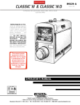
CLASSIC III/IIID
January, 1998
Gasoline & Diesel Engine Driven DC Arc Welding Power Source
For use with machine code numbers 10061, 10072 or 10156.
Return to Master TOC
View Safety Info
View Safety Info
Safety Depends on You
Return to Master TOC
Return to Master TOC
RETURN TO MAIN INDEX
Lincoln arc welding and cutting
equipment is designed and built
with safety in mind. However,
your overall safety can be increased by proper installation . . .
and thoughtful operation on
your part. DO NOT INSTALL,
OPERATE OR REPAIR THIS
EQUIPMENT WITHOUT
READING THIS MANUAL AND
THE SAFETY PRECAUTIONS
CONTAINED THROUGHOUT.
And, most importantly, think
before you act and be careful.
View Safety Info
Return to Master TOC
SERVICE MANUAL
World’s Leader in Welding and Cutting Products
Premier Manufacturer of Industrial Motors
Sales and Service through subsidiaries and Distributors Worldwide
22801 St. Clair Ave. Cleveland, Ohio 44117-1199 U.S.A. Tel. (216) 481-8100
Return to Master TOC
i
i
SAFETY
WARNING
CALIFORNIA PROPOSITION 65 WARNINGS
Diesel engine exhaust and some of its constituents
are known to the State of California to cause cancer, birth defects, and other reproductive harm.
The Above For Diesel Engines
The engine exhaust from this product contains
chemicals known to the State of California to cause
cancer, birth defects, or other reproductive harm.
The Above For Gasoline Engines
ARC WELDING CAN BE HAZARDOUS. PROTECT YOURSELF AND OTHERS FROM POSSIBLE SERIOUS INJURY OR DEATH.
KEEP CHILDREN AWAY. PACEMAKER WEARERS SHOULD CONSULT WITH THEIR DOCTOR BEFORE OPERATING.
Return to Master TOC
Return to Master TOC
Read and understand the following safety highlights. For additional safety information, it is strongly recommended that you purchase a copy of “Safety in Welding & Cutting - ANSI Standard Z49.1” from the American Welding Society, P.O. Box 351040,
Miami, Florida 33135 or CSA Standard W117.2-1974. A Free copy of “Arc Welding Safety” booklet E205 is available from the
Lincoln Electric Company, 22801 St. Clair Avenue, Cleveland, Ohio 44117-1199.
BE SURE THAT ALL INSTALLATION, OPERATION, MAINTENANCE AND REPAIR PROCEDURES ARE
PERFORMED ONLY BY QUALIFIED INDIVIDUALS.
FOR ENGINE
powered equipment.
1.h. To avoid scalding, do not remove the
radiator pressure cap when the engine is
hot.
1.a. Turn the engine off before troubleshooting and maintenance
work unless the maintenance work requires it to be running.
____________________________________________________
1.b. Operate engines in open, well-ventilated
areas or vent the engine exhaust fumes
outdoors.
____________________________________________________
1.c. Do not add the fuel near an open flame welding arc or when the engine is running. Stop
the engine and allow it to cool before refueling to prevent spilled fuel from vaporizing on
contact with hot engine parts and igniting. Do
not spill fuel when filling tank. If fuel is spilled,
wipe it up and do not start engine until fumes
have been eliminated.
____________________________________________________
1.d. Keep all equipment safety guards, covers and
devices in position and in good repair.Keep
hands, hair, clothing and tools away from Vbelts, gears, fans and all other moving parts
when starting, operating or repairing equipment.
Return to Master TOC
____________________________________________________
1.e. In some cases it may be necessary to remove safety
guards to perform required maintenance. Remove
guards only when necessary and replace them when the
maintenance requiring their removal is complete.
Always use the greatest care when working near moving
parts.
___________________________________________________
1.f. Do not put your hands near the engine fan. Do not attempt to
override the governor or idler by pushing on the throttle control rods while the engine is running.
___________________________________________________
1.g. To prevent accidentally starting gasoline engines while
turning the engine or welding generator during maintenance
work, disconnect the spark plug wires, distributor cap or
magneto wire as appropriate.
ELECTRIC AND
MAGNETIC FIELDS
may be dangerous
2.a. Electric current flowing through any conductor causes
localized Electric and Magnetic Fields (EMF). Welding
current creates EMF fields around welding cables and
welding machines
2.b. EMF fields may interfere with some pacemakers, and
welders having a pacemaker should consult their physician
before welding.
2.c. Exposure to EMF fields in welding may have other health
effects which are now not known.
2.d. All welders should use the following procedures in order to
minimize exposure to EMF fields from the welding circuit:
2.d.1. Route the electrode and work cables together - Secure
them with tape when possible.
2.d.2. Never coil the electrode lead around your body.
2.d.3. Do not place your body between the electrode and
work cables. If the electrode cable is on your right
side, the work cable should also be on your right side.
2.d.4. Connect the work cable to the workpiece as close as
possible to the area being welded.
2.d.5. Do not work next to welding power source.
Mar ‘95
Classic III and IIID
Return to Master TOC
Return to Master TOC
ii
SAFETY
ELECTRIC SHOCK can kill.
ARC RAYS can burn.
3.a. The electrode and work (or ground) circuits
are electrically “hot” when the welder is on.
Do not touch these “hot” parts with your bare
skin or wet clothing. Wear dry, hole-free
gloves to insulate hands.
4.a. Use a shield with the proper filter and cover
plates to protect your eyes from sparks and
the rays of the arc when welding or observing
open arc welding. Headshield and filter lens
should conform to ANSI Z87. I standards.
3.b. Insulate yourself from work and ground using dry insulation.
Make certain the insulation is large enough to cover your full
area of physical contact with work and ground.
4.b. Use suitable clothing made from durable flame-resistant
material to protect your skin and that of your helpers from
the arc rays.
In addition to the normal safety precautions, if welding
must be performed under electrically hazardous
conditions (in damp locations or while wearing wet
clothing; on metal structures such as floors, gratings or
scaffolds; when in cramped positions such as sitting,
kneeling or lying, if there is a high risk of unavoidable or
accidental contact with the workpiece or ground) use
the following equipment:
• Semiautomatic DC Constant Voltage (Wire) Welder.
• DC Manual (Stick) Welder.
• AC Welder with Reduced Voltage Control.
4.c. Protect other nearby personnel with suitable, non-flammable
screening and/or warn them not to watch the arc nor expose
themselves to the arc rays or to hot spatter or metal.
3.c. In semiautomatic or automatic wire welding, the electrode,
electrode reel, welding head, nozzle or semiautomatic
welding gun are also electrically “hot”.
3.d. Always be sure the work cable makes a good electrical
connection with the metal being welded. The connection
should be as close as possible to the area being welded.
3.e. Ground the work or metal to be welded to a good electrical
(earth) ground.
3.f. Maintain the electrode holder, work clamp, welding cable and
welding machine in good, safe operating condition. Replace
damaged insulation.
Return to Master TOC
ii
3.g. Never dip the electrode in water for cooling.
3.h. Never simultaneously touch electrically “hot” parts of
electrode holders connected to two welders because voltage
between the two can be the total of the open circuit voltage
of both welders.
3.i. When working above floor level, use a safety belt to protect
yourself from a fall should you get a shock.
3.j. Also see Items 6.c. and 8.
FUMES AND GASES
can be dangerous.
5.a. Welding may produce fumes and gases
hazardous to health. Avoid breathing these
fumes and gases.When welding, keep
your head out of the fume. Use enough
ventilation and/or exhaust at the arc to keep
fumes and gases away from the breathing zone. When
welding with electrodes which require special
ventilation such as stainless or hard facing (see
instructions on container or MSDS) or on lead or
cadmium plated steel and other metals or coatings
which produce highly toxic fumes, keep exposure as
low as possible and below Threshold Limit Values (TLV)
using local exhaust or mechanical ventilation. In
confined spaces or in some circumstances, outdoors, a
respirator may be required. Additional precautions are
also required when welding on galvanized steel.
5.b. Do not weld in locations near chlorinated hydrocarbon vapors
coming from degreasing, cleaning or spraying operations.
The heat and rays of the arc can react with solvent vapors to
form phosgene, a highly toxic gas, and other irritating
products.
5.c. Shielding gases used for arc welding can displace air and
cause injury or death. Always use enough ventilation,
especially in confined areas, to insure breathing air is safe.
5.d. Read and understand the manufacturer’s instructions for this
equipment and the consumables to be used, including the
material safety data sheet (MSDS) and follow your
employer’s safety practices. MSDS forms are available from
your welding distributor or from the manufacturer.
Return to Master TOC
5.e. Also see item 1.b.
Classic III and IIID
Mar ‘95
Return to Master TOC
iii
WELDING SPARKS can
cause fire or explosion.
6.a. Remove fire hazards from the welding area.
If this is not possible, cover them to prevent
the welding sparks from starting a fire.
Remember that welding sparks and hot
materials from welding can easily go through small cracks
and openings to adjacent areas. Avoid welding near
hydraulic lines. Have a fire extinguisher readily available.
6.b. Where compressed gases are to be used at the job site,
special precautions should be used to prevent hazardous
situations. Refer to “Safety in Welding and Cutting” (ANSI
Standard Z49.1) and the operating information for the
equipment being used.
Return to Master TOC
6.c. When not welding, make certain no part of the electrode
circuit is touching the work or ground. Accidental contact can
cause overheating and create a fire hazard.
6.d. Do not heat, cut or weld tanks, drums or containers until the
proper steps have been taken to insure that such procedures
will not cause flammable or toxic vapors from substances
inside. They can cause an explosion even though they have
been “cleaned”. For information, purchase “Recommended
Safe Practices for the Preparation for Welding and Cutting of
Containers and Piping That Have Held Hazardous
Substances”, AWS F4.1 from the American Welding Society
(see address above).
6.e. Vent hollow castings or containers before heating, cutting or
welding. They may explode.
6.f. Sparks and spatter are thrown from the welding arc. Wear oil
free protective garments such as leather gloves, heavy shirt,
cuffless trousers, high shoes and a cap over your hair. Wear
ear plugs when welding out of position or in confined places.
Always wear safety glasses with side shields when in a
welding area.
Return to Master TOC
iii
SAFETY
6.g. Connect the work cable to the work as close to the welding
area as practical. Work cables connected to the building
framework or other locations away from the welding area
increase the possibility of the welding current passing
through lifting chains, crane cables or other alternate circuits.
This can create fire hazards or overheat lifting chains or
cables until they fail.
6.h. Also see item 1.c.
CYLINDER may explode
if damaged.
7.a. Use only compressed gas cylinders
containing the correct shielding gas for the
process used and properly operating
regulators designed for the gas and
pressure used. All hoses, fittings, etc. should be suitable for
the application and maintained in good condition.
7.b. Always keep cylinders in an upright position securely
chained to an undercarriage or fixed support.
7.c. Cylinders should be located:
• Away from areas where they may be struck or subjected to
physical damage.
• A safe distance from arc welding or cutting operations and
any other source of heat, sparks, or flame.
7.d. Never allow the electrode, electrode holder or any other
electrically “hot” parts to touch a cylinder.
7.e. Keep your head and face away from the cylinder valve outlet
when opening the cylinder valve.
7.f. Valve protection caps should always be in place and hand
tight except when the cylinder is in use or connected for
use.
7.g. Read and follow the instructions on compressed gas
cylinders, associated equipment, and CGA publication P-l,
“Precautions for Safe Handling of Compressed Gases in
Cylinders,” available from the Compressed Gas Association
1235 Jefferson Davis Highway, Arlington, VA 22202.
FOR ELECTRICALLY
powered equipment.
8.a. Turn off input power using the disconnect
switch at the fuse box before working on
the equipment.
8.b. Install equipment in accordance with the U.S. National
Electrical Code, all local codes and the manufacturer’s
recommendations.
8.c. Ground the equipment in accordance with the U.S. National
Electrical Code and the manufacturer’s recommendations.
Return to Master TOC
Mar ‘95
Classic III and IIID
Return to Master TOC
Return to Master TOC
Return to Master TOC
Return to Master TOC
iv
iv
SAFETY
PRÉCAUTIONS DE SÛRETÉ
Pour votre propre protection lire et observer toutes les instructions
et les précautions de sûreté specifiques qui parraissent dans ce
manuel aussi bien que les précautions de sûreté générales suivantes:
Sûreté Pour Soudage A L’Arc
1. Protegez-vous contre la secousse électrique:
a. Les circuits à l’électrode et à la piéce sont sous tension
quand la machine à souder est en marche. Eviter toujours
tout contact entre les parties sous tension et la peau nue
ou les vétements mouillés. Porter des gants secs et sans
trous pour isoler les mains.
b. Faire trés attention de bien s’isoler de la masse quand on
soude dans des endroits humides, ou sur un plancher metallique ou des grilles metalliques, principalement dans
les positions assis ou couché pour lesquelles une grande
partie du corps peut être en contact avec la masse.
c. Maintenir le porte-électrode, la pince de masse, le câble de
soudage et la machine à souder en bon et sûr état defonctionnement.
d.Ne jamais plonger le porte-électrode dans l’eau pour le
refroidir.
e. Ne jamais toucher simultanément les parties sous tension
des porte-électrodes connectés à deux machines à souder parce que la tension entre les deux pinces peut être le
total de la tension à vide des deux machines.
f. Si on utilise la machine à souder comme une source de
courant pour soudage semi-automatique, ces precautions
pour le porte-électrode s’applicuent aussi au pistolet de
soudage.
2. Dans le cas de travail au dessus du niveau du sol, se protéger
contre les chutes dans le cas ou on recoit un choc. Ne jamais
enrouler le câble-électrode autour de n’importe quelle partie
du corps.
3. Un coup d’arc peut être plus sévère qu’un coup de soliel,
donc:
a. Utiliser un bon masque avec un verre filtrant approprié
ainsi qu’un verre blanc afin de se protéger les yeux du rayonnement de l’arc et des projections quand on soude ou
quand on regarde l’arc.
b. Porter des vêtements convenables afin de protéger la peau
de soudeur et des aides contre le rayonnement de l‘arc.
c. Protéger l’autre personnel travaillant à proximité au
soudage à l’aide d’écrans appropriés et non-inflammables.
4. Des gouttes de laitier en fusion sont émises de l’arc de
soudage. Se protéger avec des vêtements de protection libres
de l’huile, tels que les gants en cuir, chemise épaisse, pantalons sans revers, et chaussures montantes.
6. Eloigner les matériaux inflammables ou les recouvrir afin de
prévenir tout risque d’incendie dû aux étincelles.
7. Quand on ne soude pas, poser la pince à une endroit isolé de
la masse. Un court-circuit accidental peut provoquer un
échauffement et un risque d’incendie.
8. S’assurer que la masse est connectée le plus prés possible de
la zone de travail qu’il est pratique de le faire. Si on place la
masse sur la charpente de la construction ou d’autres endroits
éloignés de la zone de travail, on augmente le risque de voir
passer le courant de soudage par les chaines de levage,
câbles de grue, ou autres circuits. Cela peut provoquer des
risques d’incendie ou d’echauffement des chaines et des
câbles jusqu’à ce qu’ils se rompent.
9. Assurer une ventilation suffisante dans la zone de soudage.
Ceci est particuliérement important pour le soudage de tôles
galvanisées plombées, ou cadmiées ou tout autre métal qui
produit des fumeés toxiques.
10. Ne pas souder en présence de vapeurs de chlore provenant
d’opérations de dégraissage, nettoyage ou pistolage. La
chaleur ou les rayons de l’arc peuvent réagir avec les vapeurs
du solvant pour produire du phosgéne (gas fortement toxique)
ou autres produits irritants.
11. Pour obtenir de plus amples renseignements sur la sûreté, voir
le code “Code for safety in welding and cutting” CSA Standard
W 117.2-1974.
PRÉCAUTIONS DE SÛRETÉ POUR
LES MACHINES À SOUDER À
TRANSFORMATEUR ET À
REDRESSEUR
1. Relier à la terre le chassis du poste conformement au code de
l’électricité et aux recommendations du fabricant. Le dispositif
de montage ou la piece à souder doit être branché à une
bonne mise à la terre.
2. Autant que possible, I’installation et l’entretien du poste seront
effectués par un électricien qualifié.
3. Avant de faires des travaux à l’interieur de poste, la debrancher à l’interrupteur à la boite de fusibles.
4. Garder tous les couvercles et dispositifs de sûreté à leur
place.
5. Toujours porter des lunettes de sécurité dans la zone de
soudage. Utiliser des lunettes avec écrans lateraux dans les
zones où l’on pique le laitier.
Classic III and IIID
Mar. ‘93
v
v
MASTER TABLE OF CONTENTS FOR ALL SECTIONS
RETURN TO MAIN INDEX
Page
Safety .................................................................................................................................................i-iv
Installation.............................................................................................................................Section A
Technical Specifications ..............................................................................................................A-2
Safety Precautions ......................................................................................................................A-3
Location and Ventilation ..............................................................................................................A-3
Pre-operation Engine Service .....................................................................................................A-4
Electrical Output Connections.....................................................................................................A-6
Operation...............................................................................................................................Section B
Safety Instructions.......................................................................................................................B-2
General Description ....................................................................................................................B-2
Recommended Applications........................................................................................................B-3
Operational Features and Controls.............................................................................................B-3
Design Features..........................................................................................................................B-3
Welding Capability ......................................................................................................................B-4
Limitations .................................................................................................................................B-4
Controls and Settings..................................................................................................................B-5
Engine Operation ........................................................................................................................B-9
Welding Operation.....................................................................................................................B-11
Auxiliary Power .........................................................................................................................B-13
Accessories ..........................................................................................................................Section C
Maintenance ..........................................................................................................................Section D
Safety Precautions......................................................................................................................D-2
Routine and Periodic Maintenance.............................................................................................D-2
Major Component Locations .....................................................................................................D-12
Theory of Operation .............................................................................................................Section E
Troubleshooting and Repair ................................................................................................Section F
Electrical Diagrams ..............................................................................................................Section G
Parts
Parts List Classic III Diesel .....................................................................................................P-232
Parts List Classic III Gas.........................................................................................................P-302
Classic III and IIID
Return to Master TOC
Section A-1
TABLE OF CONTENTS
- INSTALLATION SECTION -
Section A-1
Installation
Technical Specifications ..............................................................................................................A-2
Safety Precautions ......................................................................................................................A-3
Location and Ventilation ..............................................................................................................A-3
Storing .................................................................................................................................A-3
Return to Master TOC
Stacking ................................................................................................................................A-4
Tilting
.................................................................................................................................A-4
Lifting
.................................................................................................................................A-4
High Altitude Operation ........................................................................................................A-4
Pre-operation Engine Service .....................................................................................................A-4
Oil ........................................................................................................................................A-4
Fuel.......................................................................................................................................A-4
Battery Connections .............................................................................................................A-4
Cooling System.....................................................................................................................A-5
Muffler .................................................................................................................................A-5
Exhaust Spark Arrester ........................................................................................................A-5
Trailer
.................................................................................................................................A-5
Electrical Output Connections.....................................................................................................A-6
Return to Master TOC
Return to Master TOC
Welding Cable Connections .................................................................................................A-6
Cable Installation and Cable Sizes ..........................................................................A-6
Machine Grounding ..............................................................................................................A-7
Auxiliary Power Receptacles, Plugs, and Hand-held Equipment .........................................A-7
Circuit Breakers ....................................................................................................................A-7
Classic III and IIID
Return to Master TOC
A-2
INSTALLATION
TECHNICAL SPECIFICATIONS - CLASSIC III AND IIID
INPUT - ENGINE
Manufacturer Description
Classic III:
Continental
TM27
Classic IIID:
Continental
TMD27
Return to Master TOC
Return to Section TOC
Return to Section TOC
A-2
4 cyl., 4 cycle
Water-cooled
Gasoline
38.9 HP @
1700 RPM
4 cyl., 4 cycle
Water-cooled
Diesel
45 HP @
1700 RPM
Speed
Displacement
Ignition
Capacities
1725 RPM
Full load
164.7 cu. in.
(2700 cc)
Electric
Fuel: 15 gal.
(57 liters)
1800 RPM
High idle
Oil: 7 qt.
(6.7 liters)
1350 RPM
Low idle
Water/coolant: 9.3 qt.
(8.8 liters)
RATED OUTPUT - WELDER
Duty Cycle
Amps
Volts at Rated Amperes
100% Duty Cycle
50% Duty Cycle
30% Duty Cycle
225 DC Constant Current
300 DC Constant Current
350 DC Constant Current
29V
32V
34V
Return to Master TOC
Return to Section TOC
OUTPUT - WELDER AND GENERATOR
Return to Master TOC
Max. Open Circuit Voltage
Auxiliary Power
40-350 Amps DC
98.5
3.0 kVA of 115/230 V, 60Hz Power
26 Amps @ 115 V(1)
13 Amps @ 230 V
PHYSICAL DIMENSIONS
1
Return to Section TOC
Welding Ranges
Height
Width
Depth
40.94 in.
1040 mm
24 in.
610 mm
66.25 in.
1683 mm
Weight
Classic III
1406 lb.
638 kg
15 amps can be drawn from either half of the receptacle. Total combined load of all receptacles cannot exceed 3.0 kVA.
Classic III and IIID
Classic IIID
1445 lb.
657 kg
Return to Section TOC
Return to Master TOC
Return to Section TOC
Return to Master TOC
A-3
INSTALLATION
Read this entire installation section before you
start installation.
SAFETY PRECAUTIONS
WARNING
Do not attempt to use this equipment until you have
thoroughly read all the operation and maintenance
manuals supplied with your machine. They include
important safety precautions; detailed engine starting,
operating, and maintenance instructions; and parts
lists.
ELECTRIC SHOCK can kill.
• Do not touch electrically live
parts or electrodes with your
skin or wet clothing.
Return to Master TOC
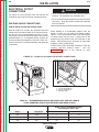
Whenever you use the welder, be sure that clean cooling air can flow through the machine’s engine and the
generator. Avoid dusty, dirty areas. Also, keep the
machine away from heat sources. Do not place the
back end of the generator anywhere near hot engine
exhaust from another machine. And of course, make
sure that engine exhaust is ventilated to an open, outside area.
The Classic III and Classic IIID may be used outdoors.
Do not set the machine in water. Such practices pose
safety hazards and cause improper operation and corrosion of parts.
• Insulate yourself from the work
and ground.
• Always wear dry insulating
gloves.
• Use in open, well ventilated
areas or vent exhaust to the outside.
Return to Section TOC
LOCATION AND VENTILATION
Always operate the Classic III and Classic IIID with the
doors closed. Leaving the doors open changes the
designed air flow and may cause overheating. Always
operate the welder with the case roof on and all
machine components completely assembled.
ENGINE EXHAUST can kill.
• Do not stack anything on or near
the engine.
MOVING PARTS can injure.
• Do not operate this equipment
with any of its doors open or
guards off.
STORING
1. Store the machine in a cool, dry place when it is not
in use. Protect it from dust and dirt. Keep it where
it can’t be accidentally damaged from construction
activities, moving vehicles, and other hazards.
2. Drain the engine oil and refill with fresh 10W30 oil.
Run the engine for about five minutes to circulate oil
to all the parts. See the Maintenance section of
this manual for details on changing oil.
3. Remove the battery, recharge it, and adjust the
electrolyte level. Store the battery in a dry, dark
place. See the Maintenance section for information
about charging the battery.
4. See your engine operation manual for further information on fuel and engine preservation.
• Stop the engine before servicing
it.
• Keep away from moving parts.
See additional safety information at the front of this
manual.
Return to Master TOC
Return to Section TOC
A-3
Only qualified personnel should install, use, or service this equipment.
Classic III and IIID
Return to Master TOC
Return to Master TOC
Return to Section TOC
Return to Section TOC
A-4
INSTALLATION
STACKING
WARNING
Classic III and Classic IIID machines CANNOT be
stacked.
Keep hands away from the engine muffler or HOT
engine parts.
• Stop the engine when fueling.
TILTING
• Do not smoke when fueling.
Place the machine on a secure, level surface whenever you use it or store it. Any surfaces you place it on
other than the ground must be firm, non-skid, and
structurally sound.
The engine is designed to run in a level position for
best performance. If you do operate it at a slight angle,
be sure to check the oil regularly and keep the oil level
at the FULL mark as it would be in its normal level condition. Also, fuel capacity will be a little less at an angle.
LIFTING
The Classic III weighs 1406 lb./638 kg. The Classic IIID
weighs 1445 lb./657 kg. A lift bail is provided for lifting
with a hoist.
• Remove the fuel cap slowly to release pressure.
• Do not overfill the fuel tank.
• Wipe up spilled fuel and allow the fumes to clear
before starting the engine.
• Keep sparks and flame away from the fuel tank.
OIL
The Classic III and Classic IIID are shipped
with the engine filled with SAE 10W-30 oil.
This should be fine for most ambient operating temperature conditions. See the engine operation manual for specific recommendations. CHECK
THE OIL LEVEL BEFORE YOU START THE ENGINE.
This is an added precaution. When full, the oil level
should be up to but not over the FULL mark on the dipstick. If it is not full, add enough oil to fill it to the full
mark. DO NOT overfill.
For more oil fill and service information, see the
Maintenance section of this manual.
WARNING
Return to Master TOC
Return to Section TOC
FALLING EQUIPMENT can
cause injury.
Do not lift this machine using the lift bail
if it is equipped with a heavy accessory
such as a trailer.
Lift only with equipment of adequate
lifting capacity. Be sure the machine is stable when lifting.
FUEL
Fill the fuel tank with the grade of fuel recommended in the engine operation manual.
The Classic III and Classic IIID have a 15
gallon (57 liter) fuel tank with a top fill and fuel gauge
mounted on the control panel. See the Operation and
Maintenance sections of this manual for more details
about fuel.
HIGH ALTITUDE OPERATION
BATTERY CONNECTIONS
Return to Master TOC
It may be necessary to derate welder output at higher
altitudes. Some engine adjustment may be required.
Contact a Continental Service Representative.
Return to Section TOC
A-4
PRE-OPERATION ENGINE SERVICE
Read and understand the information about the engine
in the Operation and Maintenance sections of this
manual before you operate the Classic III or Classic
IIID.
The Classic III and Classic IIID are shipped
with the negative battery cable disconnected. Before
you operate the machine, make sure the IGNITION
switch is in the OFF position and attach the disconnected cable securely to the battery terminal. If the
battery is discharged and won't start the engine, see
the battery charging instructions in the Maintenance
section.
Classic III and IIID
Return to Master TOC
Return to Master TOC
Return to Master TOC
Return to Master TOC
Return to Section TOC
Return to Section TOC
Return to Section TOC
Return to Section TOC
A-5
INSTALLATION
A-5
COOLING SYSTEM
TRAILER
The cooling system has been filled at the factory with a
50-50 mixture of ethylene glycol antifreeze and water.
Check the radiator level and add a 50-50 solution as
needed. (See your engine manual or antifreeze container for alternate antifreeze recommendations.)
If you use a non-Lincoln trailer, you must assume
responsibility that the method of attachment and usage
does not result in a safety hazard nor damage the
welding equipment. Some of the factors to be considered are as follows:
MUFFLER
1. Design capacity of the trailer vs. the weight of the
Lincoln equipment and likely additional attachments.
This welder is supplied with an adjustable rain cap for
the muffler. Install the rain cap using the clamp provided with the outlet facing away from the direction in
which this unit will be transported. This will minimize
the amount of water and debris that could enter the
muffler during transportation.
2. Proper support of, and attachment to, the base of
the welding equipment so there will be no undue
stress to the framework.
EXHAUST SPARK ARRESTER
4. Typical conditions of use, such as travel speed,
roughness of the surfaces where the trailer will be
used, environmental conditions, likely maintenance.
Some federal, state or local laws may require that
gasoline or diesel engines be equipped with exhaust
spark arresters when they are operated in certain locations where unarrested sparks may present a fire hazard. The standard mufflers included with these welders
do not qualify as a spark arrester. When required by
local regulations, suitable spark arresters must be
installed and properly maintained.
3. Proper placement of the equipment on the trailer to
ensure stability side to side and front to back. This
includes when being moved and when standing by
itself for operation or service.
5. Conformance with federal, state, and local laws.
Consult applicable federal, state, and local laws
about specific requirements for use on public highways.
CAUTION
Use of an incorrect arrester may lead to engine damage or performance loss. Contact the engine manufacturer for specific recommendations.
Classic III and IIID
Return to Master TOC
Return to Section TOC
A-6
A-6
INSTALLATION
ELECTRICAL OUTPUT
CONNECTIONS
CAUTION
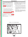
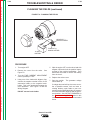
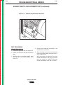
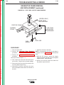
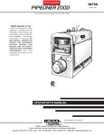
See Figure A.1 for the location of the 115 and 230 volt
receptacles, weld output terminals, and ground stud.
• Loose connections will cause the output terminals to
overheat. The terminals may eventually melt.
• Do not cross the welding cables at the output terminal
connection. Keep the cables isolated and separate
from one another.
WELDING CABLE CONNECTIONS
Return to Section TOC
Return to Master TOC
Return to Section TOC
Return to Master TOC
CABLE INSTALLATION AND CABLE SIZES
With the engine off, connect the electrode and work
cables to the terminals located on the fuel tank mounting rail. (See size recommendations below.) For positive polarity, connect the electrode cable to the terminal
marked Positive (+). For Negative polarity, connect the
electrode cable to the Negative (-) terminal. These connections should be checked periodically and tightened
if necessary.
When welding at a considerable distance from the
welder, be sure you use ample size welding cables.
Table A.1 lists recommended cable sizes and lengths
for rated current and duty cycle. Length refers to the
distance from the welder to the work and back to the
welder. Cable diameters are increased for long cable
lengths to reduce voltage drops.
Lincoln Electric offers a welding accessory kit with the
properly specified welding cables.
See the
Accessories section of this manual for more
information.
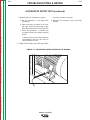
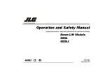
FIGURE A.1 - CLASSIC III & CLASSIC IIID OUTPUT CONNECTIONS
3
14
2
1
1.
2.
3.
4.
230 VAC RECEPTACLE
115 VAC RECEPTACLE
OUTPUT TERMINALS
GROUND STUD
Return to Master TOC
Return to Section TOC
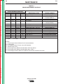
TABLE A.1 - RECOMMENDED COPPER WELDING CABLE SIZE AND LENGTH
TOTAL COMBINED LENGTH OF ELECTRODE AND WORK CABLES
Cable sizes for combined length of
electrode plus work cable
Amps
Duty Cycle
Up to 200 ft.
200 to 250 ft.
225
100%
1
1/0
300
50%
1/0
2/0
350
30%
2/0
3/0
Classic III and IIID
Return to Master TOC
Return to Master TOC
Return to Section TOC
Return to Section TOC
A-7
INSTALLATION
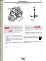
MACHINE GROUNDING
According to the United States National Electrical
Code, the frame of this portable generator is not
required to be grounded and is permitted to serve as
the grounding means for cord connected equipment
plugged into its receptacles.
Some state, local or other codes or unusual operating
circumstances may require the machine frame to be
grounded. It is recommended that you determine the
extent to which such requirements may apply to your
particular situation and follow them explicitly. A
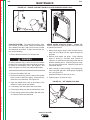
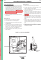
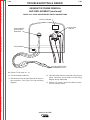
machine grounding stud marked with the symbol
is provided on the welding generator frame foot.
(If an older portable welder does not have a grounding
stud, connect the ground wire to an unpainted frame
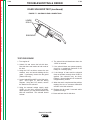
screw. See Figure A.2.
In general, if the machine is to be grounded, it should
be connected with a #8 or larger copper wire to a solid
earth ground such as a metal water pipe going into the
ground for at least ten feet and having no insulated
joints, or to the metal framework of a building which has
been effectively grounded. The U.S. National Electrical
Code lists a number of alternate means of grounding
electrical equipment.
WARNING
Return to Master TOC
Return to Section TOC
Do not ground the machine to a pipe that carries explosive or combustible material.
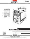
When the Classic III and Classic IIID are mounted on a
truck or a trailer, the machine generator ground stud
MUST be securely connected to the metal frame of the
vehicle. See Figure A.2. The ground stud is marked
with the ground symbol.
For further protection against electric shock, any electrical equipment connected to the generator receptacles must use a three-blade, grounded type plug or an
Underwriter's Laboratories (UL) approved double insulation system with a two-blade plug. Lincoln offers an
accessory plug kit that has the right type of plugs. See
the Accessories section of this manual for details.
If you need ground fault protection for hand-held equipment, refer to the Accessories section of this manual
for the GFCI Receptacle kit.
CIRCUIT BREAKERS
Classic III and Classic IIID welders are
equipped with circuit breakers on the
115 and the 230 volt receptacles for
overload protection. Under high heat a
breaker may tend to trip at lower loads than it would
normally.
Operation with high ambient temperatures may cause
the breakers to trip at lower than normal loads.
CAUTION
Never bypass the circuit breakers. Without overload
protection, the Classic III and Classic IIID could overheat and/or cause damage to the equipment being
used.
FIGURE A.2 - GROUND STUD LOCATION
AUXILIARY POWER RECEPTACLES,
PLUGS, AND HAND-HELD EQUIPMENT
The AC auxiliary power, supplied as a standard, has a
rating of 3.0 kVA of 115/230V AC (60 hertz).
Return to Master TOC
With the 3.0 kVA, 115/230V AC auxiliary power, one
115V duplex and one 230V duplex grounding type
receptacle are provided. The circuit is protected with
circuit breakers.
Return to Section TOC
A-7
The rating of 3.0 kVA permits a maximum continuous
current of 13 amps to be drawn from the 230 volt
duplex receptacle. Or a total of 26 amps can be drawn
from the 115 volt duplex receptacle. The 115 volt
duplex receptacle has a configuration which permits 15
amps to be drawn from either half of the receptacle.
The total combined load of all receptacles is not to
exceed 3.0 kVA.
1
1. GROUND STUD
Classic III and IIID
Return to Section TOC
Return to Master TOC
Return to Section TOC
Return to Master TOC
Return to Master TOC
Return to Section TOC
Return to Master TOC
Return to Section TOC
A-8
NOTES
Classic III and IIID
A-8
Return to Master TOC
Section B-1
Section B-1
TABLE OF CONTENTS
- OPERATION SECTION Operation...............................................................................................................................Section B
Safety Instructions.......................................................................................................................B-2
General Description ....................................................................................................................B-2
Recommended Applications .......................................................................................................B-3
Welder .................................................................................................................................B-3
Generator..............................................................................................................................B-3
Operational Features and Controls .............................................................................................B-3
Design Features ..........................................................................................................................B-3
Return to Master TOC
Welding Capability.......................................................................................................................B-4
Limitations .................................................................................................................................B-4
Controls and Settings..................................................................................................................B-5
Welder/Generator Controls ...................................................................................................B-5
Control of Welding Current ...................................................................................................B-6
Gasoline Engine Controls.....................................................................................................B-7
Diesel Engine Controls .........................................................................................................B-8
Engine Operation ........................................................................................................................B-9
Before Starting the Engine ...................................................................................................B-9
Starting the Gasoline Engine................................................................................................B-9
Starting the Diesel Engine....................................................................................................B-9
Return to Master TOC
Return to Master TOC
Stopping the Engine ...........................................................................................................B-10
Break-in Period ...................................................................................................................B-10
Welding Operation.....................................................................................................................B-11
DC Constant Current Stick or TIG Welding ........................................................................B-11
DC Wire Feed Welding (Constant Voltage).........................................................................B-12
Auxiliary Power..........................................................................................................................B-13
Classic III and IIID
Return to Master TOC
Return to Section TOC
B-2
OPERATION
WARNING
OPERATING INSTRUCTIONS
Read and understand this entire section before operating your Classic III or Classic IIID.
ENGINE EXHAUST can kill.
SAFETY INSTRUCTIONS
• Use in open, well ventilated areas or
vent exhaust to the outside.
WARNING
• Do not stack anything on or near the
engine.
Return to Master TOC
Return to Section TOC
Do not attempt to use this equipment until you have
thoroughly read all the operation and maintenance
manuals supplied with your machine. They include
important safety precautions; detailed engine starting,
operating, and maintenance instructions; and parts
lists.
Return to Master TOC
• Do not operate this equipment with any
of its doors open or guards off.
ELECTRIC SHOCK can kill.
• Do not touch electrically live parts or
electrodes with your skin or wet clothing.
• Insulate yourself from the work and
ground.
• Always wear dry insulating gloves.
• Keep your head out of fumes.
Return to Section TOC
MOVING PARTS can injure.
• Stop the engine before servicing it.
FUMES AND GASES can be dangerous.
• Use ventilation or exhaust to remove
fumes from breathing zone.
WELDING SPARKS can cause
fire or explosion.
• Keep flammable material away.
• Do not weld on containers that have held
combustibles.
• Keep away from moving parts.
Only qualified personnel should install, use, or service this equipment.
GENERAL DESCRIPTION
The Classic III and Classic IIID are heavy duty engine
driven DC arc welding power sources capable of providing constant current output for stick welding or DC
TIG welding. These welders are wound with all copper
coils and feature improved door latches and stainless
steel hinges. With the addition of the optional K623-1
Wire Feed Module, the welders will provide constant
voltage output for running the LN-7, LN-23P, or LN-25
wire feeders.
The Classic III and Classic IIID have a current range of
40-350 DC amps with a 50% duty cycle at 300
amps/32 volts. The units are also capable of providing
3.0 kVA of 115/230 volt, 60 Hertz AC auxiliary power.
The Classic III uses the Continental TM27 four-cylinder, industrial water-cooled gasoline engine, and the
Classic IIID uses the Continental TMD27 industrial
water cooled diesel engine.
ARC RAYS can burn.
Return to Master TOC
• Wear eye, ear, and body protection.
Return to Section TOC
B-2
Classic III and IIID
Return to Master TOC
Return to Section TOC
B-3
OPERATION
RECOMMENDED APPLICATIONS
DESIGN FEATURES
WELDER
• All copper windings for long life and dependable
operation.
The Classic III and Classic IIID provide excellent constant current DC welding output for stick (SMAW) welding and for DC TIG welding. When equipped with the
wire feed module, they also offer constant voltage output for DC semiautomatic wire feed welding. For more
details on using the machine as a welder, see Welding
Operation in the Operation section of this manual.
GENERATOR
The Classic III and Classic IIID are also capable of providing 3.0 kVA of 115/230 volts of 60 Hertz AC auxiliary
power.
• Constant current DC Stick welding (SMAW) process
capability with output range from 40 - 350 DC amps.
• Constant current DC TIG Welding with output across
the entire range of settings.
• Work and Electrode welding cable mounting terminals.
• Separate ground stud for safe connection of case to
earth ground.
• Duplex, 230 volt auxiliary power receptacle.
Return to Section TOC
Return to Master TOC
Return to Master TOC
Return to Master TOC
• Duplex, 115 volt auxiliary power receptacle.
Return to Section TOC
Return to Section TOC
B-3
OPERATIONAL FEATURES AND
CONTROLS
The Classic III and Classic IIID are designed for simplicity. Therefore, it has very few operating controls.
Two controls are used for welding operations:
• A five-position CURRENT RANGE SELECTOR
switch selects current output ranges for constant current stick or TIG applications and constant voltage
wire feed applications (with optional Wire Feed
Module - see the Accessories section)
• A FINE CURRENT ADJUSTMENT control for fine
adjustment of current from minimum to maximum
within each range
Controls for the engine include a two-position
IGNITION ON/OFF toggle switch, a START pushbutton, and a two-position IDLER switch that selects
engine speed for welding or auxiliary power applications. See Engine Operation in the Operation section
of this manual for details about starting, running,
stopping, and breaking in the engine.
• Integrated generator output overload protection
through four 15 amp circuit breakers.
• Electric starting.
• Battery Charging Ammeter.
• Engine Oil Pressure Gauge. (Classic III D only)
• Engine Hour Meter for determining periodic maintenance.
• Top-of-the-line 38.9 HP Continental gasoline
(Classic III) or 45 HP Continental diesel engine
(Classic IIID).
• Top-mounted 15 gallon (57.0 litter) fuel tank with convenient top fill.
• Automatic engine shutdown protection for low oil
pressure or high engine coolant temperature
(Classic IIID).
• Automatic engine idler goes to low idle approximately 15 seconds after welding for greater fuel economy;
includes high idle switch.
Classic III and IIID
Return to Master TOC
OPERATION
Return to Master TOC
Return to Master TOC
B-4
WELDING CAPABILITY
LIMITATIONS
The Classic III and Classic IIID are rated 300 amps, 32
volts constant current DC at 50% duty cycle based on
a ten minute time period. Longer duty cycles at lower
output currents are possible.
The Classic III and Classic IIID are not recommended
for any processes besides those that are normally performed using DC stick welding (SMAW) and DC TIG
welding. Specific limitations on using the Classic III
and Classic IIID for these processes are described in
the Welding Operation section of this manual.
Constant voltage welding is available with the optional
Wire Feed Module.
The current is continuously variable from 40 to 350
amps DC.
Return to Master TOC
Return to Section TOC
Return to Section TOC
Return to Section TOC
Return to Section TOC
B-4
Classic III and IIID
Return to Master TOC
Return to Section TOC
B-5
B-5
OPERATION
CONTROLS AND SETTINGS
The welder/generator controls are located on the
Output Control Panel of the machine case front.
Engine idler control and start/stop controls are also on
the case front. Welding output terminals and ground
stud are located on the machine left side, under the
door. See Figures B.1, B.2 and B.3 and the explanations that follow.
FIGURE B.1 – OUTPUT CONTROLS
1
8
2
Return to Master TOC
Return to Section TOC
3
6
4
5
Return to Master TOC
Return to Section TOC
17
1.
2.
3.
4.
5.
6.
7.
8.
WELDER/GENERATOR CONTROLS
See Figure B.1 for the location of the following features:
1. CURRENT RANGE SELECTOR: Selects ranges
of continuous current output for constant current
stick or TIG applications and constant voltage wire
feed applications (with optional Wire Feed Module).
See Control of Welding Current for more information.
Return to Master TOC
2. FINE CURRENT ADJUSTMENT: Allows fine
adjustment of current within the selected output
range. See Control of Welding Current for more
information.
Return to Section TOC
CURRENT RANGE SELECTOR
FINE CURRENT ADJUSTMENT
230 VOLT DUPLEX RECEPTACLE
115 VOLT DUPLEX RECEPTACLE
WELD OUTPUT TERMINAL (–)
WELD OUTPUT TERMINAL (+)
GROUND STUD
OPTIONAL WIRE FEED MODULE
CONTROLS
3. 230 VOLT DUPLEX RECEPTACLE: Connection
point for supplying 230 volt power to operate one or
two electrical devices.
4. 115 VOLT DUPLEX RECEPTACLE: Connection
point for supplying 115 volt power to operate one or
two electrical devices.
5. WELD OUTPUT TERMINAL (–) WITH FLANGE
NUT: Provides the connection point for either the
electrode holder or the work cable.
6. WELD OUTPUT TERMINAL (+) WITH FLANGE
NUT: Provides the connection point for either the
electrode holder or the work cable.
7. GROUND STUD: Provides a connection point for
connecting the machine case to earth ground for the
safest grounding procedure.
Classic III and IIID
Return to Master TOC
Return to Section TOC
B-6
OPERATION
CONTROL OF WELDING CURRENT
A high open circuit voltage setting provides the soft
"buttering" arc with best resistance to pop-outs preferred for most welding. To get this characteristic, set
the CURRENT RANGE SELECTOR to the lowest setting that still provides the current you need and set the
FINE CURRENT ADJUSTMENT near maximum. For
example: to obtain 175 amps and a soft arc, set the
CURRENT RANGE SELECTOR to the 190 -120 position and then adjust the FINE CURRENT ADJUSTMENT for 175 amps.
CAUTION
• DO NOT turn the CURRENT RANGE SELECTOR
while welding because the current may arc between
the contacts and damage the switch.
Return to Master TOC
• DO NOT attempt to set the CURRENT RANGE
SELECTOR between the five points designated on
the nameplate.
Return to Section TOC
B-6
When a forceful "digging" arc is required, usually for
vertical and overhead welding, use a higher CURRENT
RANGE SELECTOR setting and lower open circuit
voltage. For example: to obtain 175 amps and a forceful arc, set the CURRENT RANGE SELECTOR to 240160 position and the FINE CURRENT ADJUSTMENT
setting to get 175 amps.
See Figure B.2. The CURRENT RANGE SELECTOR
provides five overlapping current ranges. The FINE
CURRENT ADJUSTMENT adjusts the current from
minimum to maximum within each range. Open circuit
voltage is also controlled by the FINE CURRENT
ADJUSTMENT, permitting control of the arc characteristics.
Some arc instability may be experienced with EXX10
electrodes when trying to operate with long arc techniques at settings at the lower end of the open circuit
voltage range.
FIGURE B.2 – CURRENT CONTROLS
FINE CURRENT
ADJUSTMENT
CURRENT RANGE
SELECTION
190-120
240-160
130-80
60
50
Return to Section TOC
Return to Master TOC
Return to Section TOC
Return to Master TOC
70
CURRENT
RANGE
SELECTOR
220
MAX
40
80
90
MIN
30
90
20
100
IDLER
ENGINE
IGNITION PROTECTION
230 VOLT AC
115 VOLT AC
START
REMOTE
CONTROL
Classic III and IIID
10
FINE
CURRENT
ADJUSTMENT
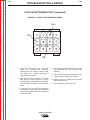
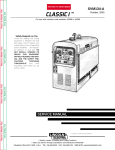
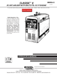
FIGURE B.3 – GASOLINE ENGINE CONTROLS
60
Return to Master TOC
Return to Master TOC
Return to Master TOC
Return to Section TOC
50
70
220
MAX
40
80
90
MIN
30
90
20
100
IDLER
IGNITION
OIL
PRESSURE
230 VOLT AC
Return to Section TOC
5
FINE CURRENT
ADJUSTMENT
CURRENT RANGE
SELECTION
190-120
240-160
130-80
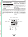
1. IDLER CONTROL TOGGLE
SWITCH
2. IGNITION TOGGLE SWITCH
3. CHOKE
4. START PUSHBUTTON
5. ENGINE HOUR METER
6. AMMETER
Return to Section TOC
B-7
OPERATION
Return to Master TOC
Return to Section TOC
B-7
6
115 VOLT AC
4
10
START
REMOTE
CONTROL
1
2
GASOLINE ENGINE CONTROLS
(CLASSIC III)
3
See Figure B.3 for the location of the following features:
4. START PUSHBUTTON: Press the START button
to start the engine. The IGNITION switch must be
in the ON position.
1. IDLER CONTROL TOGGLE SWITCH: Adjusts the
running speed of the engine. The switch has two
positions, "HIGH" and "AUTO." In "HIGH," the
engine runs continuously at high idle. In "AUTO,"
the idler control works as follows:
NOTE: If you press the START pushbutton when
the engine is running, you may damage the engine
flywheel gear or starter motor.
Welding: The engine accelerates to high speed
when the electrode touches the work and strikes a
welding arc. The engine returns to low idle approximately 15 seconds after welding stops, as long as
no auxiliary power is being drawn.
Auxiliary Power: The engine accelerates to high
speed when power is drawn at the receptacles for
lights or tools. The engine returns to low idle
approximately 15 seconds after demand for
auxiliary power stops.
5. ENGINE HOUR METER: Records engine running
time. Use the meter to determine when to
perform required maintenance.
6. AMMETER: Shows whether the charging circuit
is performing its job of charging the battery when
the engine is running. The meter will register
discharge during starting, but then the needle
should return to a position slightly toward positive
during running. The needle will hold position in the
center when the engine stops.
2. IGNITION CONTROL TOGGLE SWITCH: Has
two positions, ON and OFF. When the switch is in
the ON position, the engine can be started by
pressing the START pushbutton. When the switch
is placed in the OFF position, the engine stops.
3. CHOKE: Provides a richer air/fuel mixture for cold
engine starting conditions. See the topic Engine
Operation for details on setting the choke.
Classic III and IIID
B-8
Return to Master TOC
OPERATION
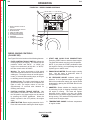
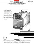
FIGURE B.4 – DIESEL ENGINE CONTROLS
3
FINE CURRENT
ADJUSTMENT
CURRENT RANGE
SELECTION
190-120
240-160
130-80
60
50
70
220
MAX
40
80
90
MIN
30
90
20
100
IDLER
Return to Master TOC
Return to Section TOC
Return to Section TOC
B-8
1. IDLER CONTROL TOGGLE
SWITCH
2. IGNITION TOGGLE SWITCH
3. RESET BUTTON
4. START PUSHBUTTONS
5. ENGINE HOUR METER
6. OIL PRESSURE GAUGE
7. AMMETER
8. TEMPERATURE GAUGE
IGNITION
RESET
230 VOLT AC
8
115 VOLT AC
5
4
10
START
REMOTE
CONTROL
1
2
7
6
DIESEL ENGINE CONTROLS
(CLASSIC IIID)
Return to Master TOC
Return to Master TOC
Return to Section TOC
Return to Section TOC
See Figure B.4 for the location of the following features:
1. IDLER CONTROL TOGGLE SWITCH: Adjusts the
running speed of the engine. The switch has two
positions, "HIGH" and "AUTO." In "HIGH," the
engine runs continuously at high idle. In "AUTO,"
the idler control works as follows:
Welding: The engine accelerates to high speed
when the electrode touches the work and strikes a
welding arc. The engine returns to low idle approximately 15 seconds after welding stops, as long as
no auxiliary power is being drawn.
Auxiliary Power: The engine accelerates to high
speed when power is drawn at the receptacles for
lights or tools. The engine returns to low idle
approximately 15 seconds after demand for
auxiliary power stops.
2. IGNITION CONTROL TOGGLE SWITCH: Has
two positions, ON and OFF. When the switch is in
the ON position, the diesel engine can be started
by pressing the START pushbutton. When the
switch is placed in the OFF position, the engine
stops.
3. RESET BUTTON: Resets engine protection circuit.
Press this button before starting the diesel engine.
4. START AND GLOW PLUG PUSHBUTTONS:
Press the START button to start the diesel engine.
The IGNITION switch must be in the ON position.
NOTE: If you press the START pushbutton when
the engine is running, you may damage the engine
flywheel gear or starter motor.
5. ENGINE HOUR METER: Records engine running
time. Use the meter to determine when to
perform required maintenance.
6. OIL PRESSURE GAUGE: Indicates engine oil
pressure. If no oil pressure shows on the gauge
within 30 seconds after startup, the engine should
be stopped by placing the IGNITION switch in the
OFF position.
7. AMMETER: Shows whether the charging circuit
is performing its job of charging the battery when
the engine is running. The meter will register
discharge during starting, but then the needle
should return to a position slightly toward positive
during running. The needle will hold position in the
center when the engine stops.
8. TEMPERATURE GAUGE: Indicates temperature
of engine coolant.
Classic III and IIID
Return to Master TOC
Return to Master TOC
Return to Section TOC
Return to Section TOC
B-9
OPERATION
STARTING THE CLASSIC III CONTINENTAL TM27 GASOLINE ENGINE
ENGINE OPERATION
WARNING
NOTE: Remove all loads connected to the AC power
receptacles before starting the engine.
DO NOT RUN THE ENGINE AT EXCESSIVE
SPEEDS. The maximum allowable high idle speed for
the Classic III and Classic IIID is 1800 RPM, no load.
Do NOT increase the idle speed on the engine. Severe
personal injury and damage to the machine can result
if it is operated at speeds above the maximum rated
speed.
1. Turn the IDLER switch to “HIGH”.
Read and understand all safety instructions included in
the Continental engine instruction manual that is
shipped with your welder.
6. Allow engine to run at high idle speed for several
minutes to warm the engine. Cold engines tend to
run at a speed too slow to supply the voltage
required for proper automatic idler operation.
BEFORE STARTING THE ENGINE
7. As engine warms, slowly return the CHOKE control
to the OFF position.
Return to Master TOC
4. Press the START button.
5. If the engine fails to start in 60 seconds, wait 30
seconds before repeating the above procedure.
STARTING THE CLASSIC IIID CONTINENTAL TMD27 ENGINE
2. Remove the engine oil dipstick and wipe it with a
clean cloth. Reinsert the dipstick and check the
level on the dipstick.
See Figure D.1 in the
Maintenance section of this manual.
NOTE: Remove all loads connected to the AC power
receptacles before starting the engine.
1. Place the IDLER switch in the "HIGH" position and
the IGNITION switch in the ON position. Press the
RESET button.
2. Press the GLOW PLUG button for 10 to 20 seconds.
3. While holding down the GLOW PLUG button, press
the START button. Release both buttons when the
engine starts.
Check and fill the engine fuel tank:
WARNING
Do not add fuel near an open flame,
welding arc or when the engine is running. Stop the engine and allow it to
cool before refueling to prevent spilled
fuel from vaporizing on contact with
hot engine parts and igniting. Do not
spill fuel when filling tank. If fuel is spilled, wipe it up
and do not start engine until fumes have been eliminated.
1. Remove the fuel tank cap.
Return to Master TOC
3. Pull out the CHOKE control.
1. Be sure the machine is on a level
surface.
4. Replace the dipstick.
Return to Section TOC
2. Turn the IGNITION switch to ON.
Check and fill the engine oil level:
3. Add oil (if necessary) to bring the level up to the full
mark. Do not overfill.
Return to Section TOC
B-9
2. Fill the tank to allow approximately 1/4 inch (5 mm)
of tank space for fuel expansion. DO NOT FILL
THE TANK TO THE POINT OF OVERFLOW.
3. Replace the fuel tank cap and tighten securely.
NOTE: If the engine fails to start in 60 seconds, the
RESET button will pop out. Wait 30 seconds then
repeat step 1, 2, and 3.
4. When the engine starts running, observe the oil
pressure. If no pressure shows within 30 seconds,
stop the engine and consult the engine operating
manual.
5. Allow the engine to run at high idle for several minutes to warm the engine prior to welding. Extreme
cold weather may require longer glow plug operation.
WARNING
Under NO conditions should ether or other starting
fluids be used in conjunction with the glow plugs. This
may cause an explosion or fire!
NOTE: Purchase fuel in quantities that will be used
within 30 days, to assure freshness.
Classic III and IIID
Return to Master TOC
Return to Master TOC
Return to Section TOC
Return to Section TOC
B-10
B-10
OPERATION
STOPPING THE ENGINE
(GASOLINE OR DIESEL)
BREAK-IN PERIOD
1. Place the IGNITION switch in the OFF position.
At the end of each day’s welding, drain accumulated
dirt and water from the sediment bowl under the fuel
tank and from the fuel filter (diesel engine, Classic IIID)
per instructions in the engine manufacturer’s operating
manual. Refill the fuel tank to minimize moisture condensation in the tank. Also, running out of fuel tends to
draw dirt into the fuel system. Check the crankcase oil
level.
When hauling the welder between job sites, close the
fuel feed valve beneath the tank. In gasoline engines,
failing to turn off the fuel when traveling can cause carburetor flooding and difficult starting at the new job site.
In diesel engines, if the fuel supply is cut off or runs out
while the fuel pump is operating, air may be entrapped
in the fuel distribution system. See “How to Eliminate
Air From the Fuel System” in the Maintenance section.
When an engine is started for the first time, some of the
oil will be needed to fill the passages of the lubricating
system. Therefore, on initial starting, run the engine for
about five minutes and then stop the engine and
recheck the oil. If the level is down, fill to the full mark
again.
The engine controls were properly set at the factory
and should require no adjusting when received.
Any engine will use a small amount of oil during its
break-in period. For the gasoline or diesel engine on
the Classic III or Classic IIID, break-in is about 200 running hours.
Check the oil twice a day during break-in. Change the
oil and oil filter cartridge after the first 25 hours of operation. Also change the fuel filter cartridge on the diesel
engine. For more details, see the Maintenance section of this manual.
CAUTION
Return to Section TOC
Return to Master TOC
Return to Section TOC
Return to Master TOC
During break-in, subject the Classic III or Classic IIID to
only moderate loads. Avoid long periods running at
idle. Before stopping the engine, remove all loads and
allow the engine to cool several minutes.
Classic III and IIID
Return to Master TOC
Return to Section TOC
B-11
OPERATION
WELDING OPERATION
TO USE THE CLASSIC III OR CLASSIC IIID
FOR DC CONSTANT CURRENT STICK OR
TIG WELDING:
After you finish welding:
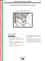
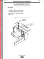
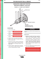
1. Remove the flange nuts from the weld output terminals and place the work and electrode welding
cables over the terminals. See Figure B.5.
Replace and tighten the flange nuts securely. Be
sure the connections are tight.
1. Stop the engine. See Engine Operation in this
section of the manual.
2. Allow the electrode and work to cool completely.
3. Remove the work clamp from the work.
2. Select the appropriate electrode.
4. Remove any remaining piece of electrode from the
electrode holder.
Return to Master TOC
Return to Section TOC
3. Attach the work clamp securely to the work you are
welding.
4. Insert the electrode into the electrode holder.
5. Start the engine. See Engine Operation in this
section of the manual.
6. Set the Idler Switch to “AUTO.”
7. Set the CURRENT RANGE SELECTOR to a setting equal to or slightly higher than the desired
welding current.
8. Set the FINE CURRENT ADJUSTMENT to the setting that gives the best arc characteristics for the
range selected. See Control of Welding Current
in this section of the manual.
Return to Master TOC
Return to Section TOC
9. Strike an arc and begin welding.
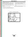
FIGURE B.5 – WELDING CIRCUIT CONNECTIONS FOR STICK WELDING
1.
2.
3.
4.
5.
6.
7.
FLANGE NUT
ELECTRODE CABLE
ELECTRODE HOLDER
ELECTRODE
WORK
WORK CLAMP
WORK CABLE
1
7
Return to Master TOC
6
Return to Section TOC
B-11
5
4
3
2
Classic III and IIID
Return to Master TOC
Return to Section TOC
B-12
B-12
OPERATION
TO USE THE CLASSIC III OR CLASSIC
IIID FOR DC WIRE FEED WELDING
(CONSTANT VOLTAGE WITH WIRE FEED
MODULE):
1. Connect the LN-25, LN-23P, or LN-7 Wire Feeder.
Follow the installation instructions provided with
the wire feeder.
2. Set the machine for CV operation.
3. Start the engine. See Engine Operation in this
section of the manual.
Return to Master TOC
Return to Section TOC
4. Set the Idler Switch to "AUTO."
5. Set the CURRENT RANGE SELECTOR to a setting appropriate for your wire size and wire feed
speed. See Table B.1 for recommended settings.
6. Set the VOLTAGE ADJUSTMENT to the setting
that gives the best arc characteristics for the range
selected.
7. Pull the gun trigger and begin welding.
TABLE B.1
RANGE SETTINGS FOR WIRE SIZE/SPEED
Return to Section TOC
Return to Master TOC
Return to Section TOC
Return to Master TOC
Diameter (inches)
Wire Speed Range
(inches/minute)
Appropriate Current Range
.035
80-110
80 to 130 Amps
.045
70-130
120 to 190 Amps
.068
40-90
150 to 240 Amps
Classic III and IIID
Return to Master TOC
Return to Section TOC
B-13
OPERATION
AUXILIARY POWER
WARNING
To use the generator as an auxiliary power supply:
Be sure that any electrical equipment plugged into the
generator AC power receptacles can withstand a ±10%
voltage and a ±3% frequency variation.
Return to Master TOC
Return to Section TOC
1. Start the diesel engine. See Engine Operation in
this section of the manual.
2. Set the IDLER switch to AUTO. Set the CURRENT
RANGE SELECTOR to “MAX.” See Figure B.1.
The AC auxiliary power, supplied as a standard, has a
rating of 3.0 kVA of 115/230V AC power (60 hertz).
3. Plug the load(s) into the appropriate 115 volt or
230 volt power receptacle.
One 115V duplex and one 230V duplex grounding type
receptacle are provided. The circuit is protected with
circuit breakers.
The rating of 3.0 kVA permits a maximum continuous
current of 13 amps to be drawn from the 230 volt
duplex receptacle. Or a total of 26 amps can be drawn
from the 115 volt duplex receptacle. The 115 volt
duplex receptacle permits 15 amps to be drawn from
either half. The total combined load of all receptacles
must not exceed 3.0 kVA.
Return to Section TOC
Return to Master TOC
Return to Master TOC
An optional power plug kit is available. When this kit is
specified, the customer is supplied with a plug for each
receptacle. See the Accessories section of this manual.
Return to Section TOC
B-13
An optional GFCI 115 volt receptacle kit is also available. Note that the use of this GFCI kit reduces available
current to a total of 20 Amps of available 115 volt power.
See the Accessories section of this manual.
Classic III and IIID
Return to Section TOC
Return to Master TOC
Return to Section TOC
Return to Master TOC
Return to Master TOC
Return to Section TOC
Return to Master TOC
Return to Section TOC
B-14
NOTES
Classic III and IIID
B-14
Return to Master TOC
Section C-1
Section C-1
TABLE OF CONTENTS
- ACCESSORIES Accessories...........................................................................................................................Section C
Options/Accessories ...................................................................................................................C-2
TIG Welding Accessories............................................................................................................C-3
Semiautomatic FCAW and MIG Welding Accessories ...............................................................C-3
Connection of Lincoln Electric Wire Feeders..............................................................................C-4
Connection of the LN-7 using K867 Universal Adapter .......................................................C-4
Connection of the LN-7 using K584 Input Cable Assembly .................................................C-5
Connection of the LN-25 using K867 Universal Adapter .....................................................C-6
Connection of the LN-23P using the K1350-1 Adapter Kit ..................................................C-8
Connection of the K488 SG Control Module and K487 Magnum Spool Gun ......................C-9
Return to Master TOC
Return to Master TOC
Return to Master TOC
Connection of the LN-25 “Across the Arc” ...........................................................................C-7
Classic III and IIID
Return to Master TOC
Return to Section TOC
C-2
ACCESSORIES
OPTIONS/ACCESSORIES
The following options/accessories are available for your
Classic III or Classic IIID from your local Lincoln
Distributor.
Trailer (K913) - Two-wheeled trailer for in-plant and
yard towing. Various hitches and accessories are
available. For highway use, consult applicable federal,
state, and local laws.
C-2
Wire Feed Module - (K623-1) - Provides constant
voltage output for semiautomatic welding. Includes
remote for CV mode and internal “Cold Tip Contactor.”
Accessory Kit (K703) - Includes the following:
• Electrode cable
• Work cable
• Headshield
• Work clamp
Return to Master TOC
Return to Section TOC
Trailer (K780) - Two-wheeled trailer with brakes, lights,
and fenders. (For highway use, consult applicable
state and local laws.)
Power Plug Kit (K802-C) - Provides a plug for each
auxiliary receptacle.
Linc Thaw™ Control Unit (L2964-5) - Includes meter
and fuses to protect the welder when thawing frozen
water pipes.
WARNING
• Insulated electrode holder
Remote Control - (K924-1) - Includes a receptacle
switch and control box with 100 ft. (7.5 meters) of 4conductor cable. Allows fine current and OCV to be
controlled remotely.
GFCI Receptacle Kit (K896-2) - Includes a UL
approved 115 volt ground fault circuit interrupter receptacle (duplex type) with covers and installation instructions. Each half of the receptacle is rated 15 amps, but
the maximum total current from the GFCI duplex is limited to 20 amps. The GFCI receptacle replaces the factory installed 115 volt duplex receptacle.
Return to Section TOC
Return to Master TOC
Return to Section TOC
Return to Master TOC
PIPE THAWING is not a CSA approved procedure. If
not done properly, it can result in fire, explosion, damage to pipes, wiring, and the welder as well as other
unsafe or hazardous conditions. Do not use a welder
to thaw pipes before reviewing Lincoln Bulletin E695.1
(dated October 1987 or later).
Classic III and IIID
Return to Master TOC
Return to Section TOC
C-3
ACCESSORIES
C-3
TIG WELDING ACCESSORIES
SEMIAUTOMATIC WELDING ACCESSORIES
K930-2 TIG Module - The TIG Module is an accessory
that provides high frequency & shielding gas control for
DC GTAW (TIG) welding applications.
LN-25 Wire Feeder - This portable wire feeder is capable of CC/CV wire feed welding.
The TIG Module is supplied without accessories. Arc
start switches, amptrols, cables, torches and mounting
brackets must be purchased separately.
LN-7 Wire Feeder - Semiautomatic, constant speed
wire feeder. For CV operation only.
LN-23P Wire Feeder - Portable CV unit for Innershield
pipe welding. Control cable operates contactor inside
wire feed module for “cold” electrode. Requires K350
and K867 adapter cables.
Return to Master TOC
Return to Master TOC
Return to Master TOC
Return to Section TOC
Return to Section TOC
Return to Section TOC
NOTE: Gas-shielded welding requires a Magnum Gun.
Gasless welding requires an Innershield Gun.
Magnum Spool Gun (K487-25) - A lightweight, semiautomatic wire feeder for aluminum welding with argon
gas. Has built-in remote wire speed control in the handle. Requires the K488 SG Control Module with appropriate control cable. Includes 25 feet (7.6 meters) of
power cable.
Classic III and IIID
Return to Master TOC
Return to Section TOC
C-4
ACCESSORIES
CONNECTION OF LINCOLN ELECTRIC WIRE FEEDERS
CONNECTION OF THE LN-7 TO THE
CLASSIC III OR CLASSIC IIID (EQUIPPED
WITH K623-1 WIRE FEED MODULE)
USING K867 UNIVERSAL ADAPTER
(SEE FIGURE C.1.)
4. Connect the K291 or K404 input cable to the LN-7.
5. Place the IDLER switch in the “HIGH” position.
CAUTION
Any increase of the high idle engine RPM by changing
the governor setting or overriding the throttle linkage
will cause an increase in the AC auxiliary voltage. If
this voltage goes over 140 volts, wire feeder control
circuits may be damaged. The engine governor setting is preset at the factory — do not adjust above
RPM specifications listed in this manual.
1. Shut the welder off.
2. Connect the electrode cable from the LN-7 to the
“+” terminal of the welder. Connect the work
cable to the “CV–” terminal of the welder.
Return to Master TOC
NOTE: Welding cable must be sized for current and
duty cycle of application.
Return to Section TOC
C-4
NOTE: Figure C.1 shows the electrode connected for
positive polarity. To change polarity, shut the welder
off and reverse the electrode and work cables at the
Classic III or Classic IIID output terminals.
6. Adjust wire feed speed at the LN-7.
NOTE: For remote control, a K775 remote control is
required. See Figure C.1.
3. Connect the K867 Universal Adapter to the K291 or
K404 input cable and the 14 pin amphenol of the
Classic III or Classic IIID as indicated in Figure C.1.
Make the proper connections for local or remote
control according to Figure C.1.
CAUTION
When the welder is in local control, the electrode is
always “HOT.”
Return to Master TOC
Return to Section TOC
FIGURE C.1
CLASSIC III OR CLASSIC IIID/LN-7 WITH K867 ADAPTER CONNECTION DIAGRAM
14 PIN
AMPHENOL
CVK867 UNIVERSAL
ADAPTER PLUG
Return to Master TOC
ELECTRODE CABLE
TO LN-7
Return to Section TOC
Insulate Each
Unused Lead
Individually
31
32
2
4
21
GND
+
TO
WORK
SPARE
82
81
42
41
75
76
77
31
32
2
4
21
GND
GREEN
75
76
77
Splice Leads
and Insulate
Classic III and IIID
LN-7
CONTROL
BOX
K291 OR K404
INPUT CABLE
K775 OPTIONAL
REMOTE CONTROL
Return to Master TOC
Return to Section TOC
C-5
ACCESSORIES
CONNECTION OF THE LN-7 TO THE
CLASSIC III OR CLASSIC IIID (EQUIPPED
WITH K623-1 WIRE FEED MODULE)
USING K584 INPUT CABLE ASSEMBLY
(SEE FIGURE C.2.)
1. Shut the welder off.
2. Connect the electrode cable from the LN-7 to the
“+” terminal of the welder. Connect the work cable
to the “CV-” terminal of the welder.
Return to Master TOC
NOTE: Welding cable must be sized for current and
duty cycle of application.
Return to Section TOC
C-5
NOTE: Figure C.2 shows the electrode connected for
positive polarity. To change polarity, shut the welder
off and reverse the electrode and work cables at the
Classic III or Classic IIID output terminals.
3. Connect the input cable from the K584-XX Input
Cable Assembly to the 14 pin amphenol on the
K864 adapter and the input cable plug on the LN7.
CAUTION
Any increase of the high idle engine RPM by changing
the governor setting or overriding the throttle linkage
will cause an increase in the AC auxiliary voltage. If
this voltage goes over 140 volts, wire feeder control
circuits may be damaged. The engine governor setting is preset at the factory — do not adjust above
RPM specifications listed in this manual.
6. Adjust wire feed speed at the LN-7.
NOTE: For remote control, a K857 control is required.
Connect it to the K864 adapter.
CAUTION
When the welder is in local control, the electrode is
always “HOT.”
4. Connect the K864 adapter to the 14 pin amphenol
on the Classic III or Classic IIID.
5. Place the IDLER switch in the “HIGH” position.
Return to Master TOC
Return to Section TOC
FIGURE C.2
CLASSIC III OR CLASSIC IIID/LN-7 WITH K584 INPUT CABLE ASSEMBLY CONNECTION DIAGRAM
14 PIN
AMPHENOL
K584-"L" INPUT CABLE
+
CVK864
ADAPTER
TO
WORK
Return to Master TOC
6 PIN
AMPHENOL
K857
REMOTE CONTROL
ELECTRODE CABLE
TO LN-7
Return to Section TOC
LN-7
CONTROL
BOX
14 PIN
AMPHENOL
Classic III and IIID
Return to Master TOC
Return to Section TOC
C-6
ACCESSORIES
CONNECTION OF THE LN-25 TO THE
CLASSIC III OR CLASSIC IIID (EQUIPPED
WITH K623-1 WIRE FEED MODULE)
USING K867 UNIVERSAL ADAPTER
(SEE FIGURE C.3.)
4. Connect the K432-L cable to the LN-25 equipped
with the K431-1 remote output control kit.
5. Place the IDLER switch in the “HIGH” position.
CAUTION
1. Shut the welder off.
2. Connect the electrode cable from the LN-25 to the
“+” terminal of the welder. Connect the work cable
to the “CV-” terminal of the welder.
Return to Master TOC
Return to Master TOC
Return to Section TOC
Return to Section TOC
NOTE: Welding cable must be sized for current and
duty cycle of application.
NOTE: Figure C.3 shows the electrode connected for
positive polarity. To change polarity, shut the welder
off and reverse the electrode and work cables at the
Classic III or Classic IIID output terminals. Reverse the
LN-25 polarity switch.
Any increase of the high idle engine RPM by changing
the governor setting or overriding the throttle linkage
will cause an increase in the AC auxiliary voltage. If
this voltage goes over 140 volts, wire feeder control
circuits may be damaged. The engine governor setting is preset at the factory — do not adjust above
RPM specifications listed in this manual.
6. Adjust wire feed speed and voltage at the LN-25.
3. Connect the K867 Universal adapter to the K433
cable and the 14 pin amphenol of the Classic III or
Classic IIID as indicated in Figure C.3. Mount the
K433 to the welder according to instructions
included with the K433 kit.
FIGURE C.3
CLASSIC III OR CLASSIC IIID/LN-25 CONNECTION DIAGRAM
14 PIN
AMPHENOL
+
CVK867 UNIVERSAL
ADAPTER PLUG
TO
WORK
SPARE
82
81
42
41
21
Insulate Each
Unused Lead
Individually
31
32
2
4
GND
31
32
2
4
GND
75
76
77
75
76
77
Splice Leads and Insulate
Return to Master TOC
ELECTRODE CABLE
Return to Section TOC
C-6
Classic III and IIID
K433
K432-"L" CABLE
LN-25 WIRE FEEDER
WITH K431 OPTION
Return to Master TOC
Return to Section TOC
C-7
ACCESSORIES
CONNECTION OF THE LN-25 TO THE
CLASSIC III OR CLASSIC IIID (EQUIPPED
WITH K623-1 WIRE FEED MODULE)
“ACROSS THE ARC” (SEE FIGURE C.4.)
1. Shut the welder off.
2. Connect the electrode cable from the LN-25 to the
“+” terminal of the welder. Connect the work cable
to the “CV–” terminal of the welder.
Return to Section TOC
Return to Master TOC
Return to Section TOC
Return to Master TOC
NOTE: Welding cable must be sized for current and
duty cycle of application.
LN-25 polarity switch.
3. Connect the K444-2 remote control cable to the 14
pin amphenol on the wire feed module.
4. Attach the single lead from the LN-25 control box
to the work using the spring clip on the end of the
lead. This is only a control lead — it carries no
welding current.
5. Place the IDLER switch in the “HIGH” position.
6. Adjust wire feed speed and voltage at the LN-25.
NOTE: Figure C.4 shows the electrode connected for
positive polarity. To change polarity, shut the welder
off and reverse the electrode and work cables at the
Classic III or Classic IIID output terminals. Reverse the
FIGURE C.4
CLASSIC III OR CLASSIC IIID/LN-25 ACROSS THE ARC CONNECTION DIAGRAM
14 PIN
AMPHENOL
+
LN-25 WIRE FEEDER
WITH K444-2 REMOTE
VOLTAGECONTROL OPTION
CV-
ELECTRODE CABLE
Return to Master TOC
TO
WORK
Return to Section TOC
C-7
WORK CLIP
LEAD TO WORK
Classic III and IIID
Return to Master TOC
Return to Section TOC
C-8
INSTALLATION
6. Connect control lead marked “21” to the work as
indicated in Figure C.5.
CONNECTION OF THE LN-23P TO THE
CLASSIC III OR CLASSIC IIID (EQUIPPED
WITH K623-1 WIRE FEED MODULE) USING
THE K-350-1 ADAPTER KIT (SEE FIGURE
C.5)
7. Set the CURRENT RANGE SELECTOR switch to
the 190-120 (middle) position for most common
processes. This may be changed if a different arc
characteristic is preferred.
1. Shut the welder off.
8. Set the LOCAL/REMOTE control toggle switch to
REMOTE.
2. Connect the electrode cable from the LN-23P to the
“CV” output terminal of the engine welder. Connect
the work cable to the “+” output terminal.
9. Set the IDLER switch to the AUTO position. The
HIGH position may be required when welding with
low current processes.
Return to Master TOC
NOTE: Welding cable must be sized for current and
duty cycle of application.
Return to Section TOC
C-8
3. Mount the K350-1 adapter per instructions included
with the adapter.
CAUTION
Any increase of the high idle engine RPM by changing
the governor setting or overriding the throttle linkage
will cause an increase in the AC auxiliary voltage. If
this voltage goes over 140 volts, wire feeder control
circuits may be damaged. The engine governor setting is preset at the factory –– do not adjust above
RPM specification listed in the manual.
4. Connect the LN-23P to the K350-1 adapter as indicated in Figure C.5. The adapter allows two wire
feeders to be connected. If only one is used, connect it to Feeder “A” terminal strip.
5. Connect the adapter cable from the K350-1 to the
14-pin amphenol on the Classic III or Classic IIID
wire feed module.
WARNING
Return to Master TOC
Return to Section TOC
The output terminals are energized when the engine is
running. The CV output will be de-energized only if
WFM mode switch is in remote position.
FIGURE C.5
CLASSIC III OR CLASSIC IIID/LN-23P CONNECTION DIAGRAM
14 PIN
AMPHENOL
+
31
32
2
4
GND
CV-
Return to Master TOC
Return to Section TOC
TO
WORK
SPARE
82
81
42
41
21
K867 UNIVERSAL
ADAPTER PLUG
ELECTRODE CABLE TO
K438 SG CONTROL CABLE
75
76
77
Insulate Each
Unused Lead
Individually
31
32
2
4
GND
GREEN
75
76
77
Splice Leads
and Insulate
Classic III and IIID
K488 SG
CONTROL
MODULE
K487-25
SPOOL
GUN
K492
INPUT CABLE
K775 OPTIONAL
REMOTE CONTROL
Return to Master TOC
Return to Section TOC
C-9
ACCESSORIES
CONNECTION OF THE K488 SG CONTROL
MODULE AND K487 MAGNUM SPOOL GUN
TO THE CLASSIC III OR CLASSIC IIID
(EQUIPPED WITH K623-1 WIRE FEED
MODULE) (SEE FIGURE C.6.)
6. Place the IDLER switch on the Classic III or Classic
IIID in the “HIGH” position.
1. Shut the welder off.
Any increase of the high idle engine RPM by changing
the governor setting or overriding the throttle linkage
will cause an increase in the AC auxiliary voltage. If
this voltage goes over 140 volts, wire feeder control
circuits may be damaged. The engine governor setting is preset at the factory — do not adjust above
RPM specifications listed in this manual.
CAUTION
2. Connect the electrode cable from the SG Control
Module to the “+” terminal of the welder. Connect
the work cable to the “CV–” terminal of the welder.
Return to Master TOC
NOTE: Welding cable must be sized for current
and duty cycle of application.
Return to Section TOC
C-9
NOTE: Figure C.6 shows the electrode connected
for positive polarity. To change polarity, shut the
welder off and reverse the electrode and work
cables at the Classic III or Classic IIID output terminals.
7. Adjust wire feed speed at the SG Control Module.
NOTE: For remote control, a K775 remote control is
required.
3. Connect the K867 Universal adapter to the K492
input cable as shown in Figure C.6. Connect the
other end of the adapter to the 14 pin amphenol on
the Classic III or Classic IIID.
CAUTION
When the welder is in local control, the electrode is
always “HOT.”
4. Connect the K492 Input Cable to the SG Control
Module.
5. Set the slide switch on the SG Control Module to
the “Lincoln” position.
Return to Master TOC
Return to Section TOC
CAUTION
Be sure this switch is set to the “Lincoln” (contact closure) position before attempting to operate the SG
Control Module. Incorrect switch position could result
in damage to the SG Control Module and/or the
Classic III or Classic IIID.
FIGURE C.6
CLASSIC III OR CLASSIC IIID/K492/K488/K487 SPOOL GUN CONNECTION DIAGRAM
14 PIN
AMPHENOL
Return to Master TOC
Return to Section TOC
+
Insulate Each
Unused Lead
Individually
31
32
2
4
GND
CVTO
WORK
SPARE
82
81
42
41
21
K867 UNIVERSAL
ADAPTER PLUG
ELECTRODE CABLE TO
K438 SG CONTROL CABLE
75
76
77
31
32
2
4
GND
GREEN
75
76
77
Splice Leads
and Insulate
Classic III and IIID
K488 SG
CONTROL
MODULE
K487-25
SPOOL
GUN
K492
INPUT CABLE
K775 OPTIONAL
REMOTE CONTROL
Return to Section TOC
Return to Master TOC
Return to Section TOC
Return to Master TOC
Return to Master TOC
Return to Section TOC
Return to Master TOC
Return to Section TOC
C-10
NOTES
Classic III and IIID
C-10
Return to Master TOC
Section D-1
Section D-1
TABLE OF CONTENTS
-MAINTENANCEMaintenance .........................................................................................................................Section D
Safety Precautions ......................................................................................................................D-2
Routine and Periodic Maintenance .............................................................................................D-2
Engine Maintenance.......................................................................................................D-2
Change the Oil ........................................................................................................D-2
Change the Oil Filter ...............................................................................................D-3
Fuel..........................................................................................................................D-3
Fuel Filter.................................................................................................................D-4
Return to Master TOC
Air Cleaner...............................................................................................................D-4
How to Eliminate Air From the Fuel System ...........................................................D-5
Cooling System .......................................................................................................D-6
Spark Plugs .............................................................................................................D-6
Tightening the Fan Belt ...........................................................................................D-7
Engine Maintenance Schedule................................................................................D-8
Battery Maintenance ......................................................................................................D-9
Cleaning the Battery................................................................................................D-9
Checking Specific Gravity........................................................................................D-9
Checking Electrolyte Level ......................................................................................D-9
Charging the Battery ...............................................................................................D-9
Return to Master TOC
Welder/Generator Maintenance ...................................................................................D-10
Storage ..................................................................................................................D-10
Cleaning ................................................................................................................D-10
Nameplates ...........................................................................................................D-10
Commutator and Brushes .....................................................................................D-10
Bearings ................................................................................................................D-10
Current Range Selector Contacts .........................................................................D-10
Receptacles ...........................................................................................................D-10
Cable Connections ................................................................................................D-10
Idler Maintenance.........................................................................................................D-11
Return to Master TOC
Major Component Locations .....................................................................................................D-12
Classic III and IIID
Return to Master TOC
Return to Section TOC
D-2
MAINTENANCE
SAFETY PRECAUTIONS
ROUTINE AND PERIODIC
MAINTENANCE
WARNING
ENGINE MAINTENANCE
• Have qualified personnel do all maintenance and
troubleshooting work.
• Turn the engine off before working inside the
machine.
• Remove covers or guards only when necessary to
perform maintenance and replace them when the
maintenance requiring their removal is complete.
Return to Master TOC
• If covers or guards are missing from the machine, get
replacements from a Lincoln Distributor.
Return to Section TOC
D-2
Read the Safety Precautions in the front of this manual and in the instruction manual for the engine used
with your machine before working on the Classic III or
Classic IIID.
Keep all equipment safety guards, covers, and devices
in position and in good repair. Keep your hands, hair,
clothing, and tools away from the recoil housing, fans,
and all other moving parts when starting, operating, or
repairing this machine.
CAUTION
To prevent the engine from accidentally starting, disconnect the negative battery cable before servicing the
engine.
See Table D.1 for a summary of maintenance intervals
for the items listed below. Follow either the hourly or
the calendar intervals, whichever come first. More frequent service may be required, depending on your specific application and operating conditions.
OIL: Check the oil level after every 8
hours of operation or daily. BE SURE TO
MAINTAIN THE OIL LEVEL.
Change the oil the first time between 25 and 50 hours
of operation. Then, under normal operating conditions,
change the oil as specified in Table D.1. If the engine is
operated under heavy load or in high ambient temperatures, change the oil more frequently.
Return to Master TOC
Return to Section TOC
CHANGE THE OIL: Change the oil, while the engine
is still warm, as follows:
1 . Drain the oil from the drain plug located on the
engine bottom, as shown in Figure D.1. If the plug
is equipped with a washer, examine and replace it
if it appears damaged.
2. Replace the plug and washer and tighten securely.
3. Remove the oil fill cap and add oil until the level
reaches the “MAX” mark on the dipstick. See
Figure D.1. Use high quality oil viscosity grade
10W30. Consult the engine manual for oil specifications. Always check the level with the dipstick
before adding more oil.
Return to Master TOC
Return to Section TOC
4.
Reinstall the oil fill cap and the dipstick.
Classic III and IIID
Return to Master TOC
Return to Section TOC
D-3
D-3
MAINTENANCE
FIGURE D.1 – OIL DRAIN AND REFILL
2
5
Return to Master TOC
Return to Master TOC
Return to Section TOC
Return to Section TOC
4
1.
2.
3.
4.
5.
3
1
CHANGE THE OIL FILTER: Change the oil filter the
first time between 25 and 50 hours of operation. Then,
under normal operating conditions, change the oil filter
per Table D.1 or consult your engine Owner’s Manual.
If the engine is operated under heavy load or in high
ambient temperatures, change the oil filter more frequently. See Table D.1 for recommended maintenance
intervals. Order Fram oil filter #PH-8A or Purolator
#PER-1A from your local engine service center.
Change the oil filter as follows:
1. See Figure D.1. Remove the oil drain plug (1).
Drain the oil from the engine and allow the oil filter
to drain.
2. See Figure D.1. Remove the old filter (spin it off)
and discard it (2). Wipe off the filter mounting surface and adapter.
3. Fill the new filter with fresh engine oil. Apply a thin
coat of new oil to the rubber gasket on the new oil
filter.
Return to Master TOC
MAX
MIN
OIL DRAIN PLUG (LOCATION)
OIL FILL CAP
DIPSTICK
OIL FILTER
DIPSTICK LEVELS
5. Refill the engine with the proper amount and type
of oil as described in the Change the Oil section,
above. Start the engine and check for leaks around
the filter element. Correct any leaks (usually by
retightening the filter, but only enough to stop
leaks) before placing the Classic III or Classic IIID
back in service.
6. See Figure D.1. If there are no leaks, stop the
engine and recheck the oil level. If necessary, add
oil to bring the level up to the “MAX” mark, but do
not overfill.
FUEL: At the end of each day's use, refill
the fuel tank to minimize moisture condensation and dirt contamination in the fuel line.
Do not overfill; leave room for the fuel to
expand.
Refer to your engine Owner’s Manual for recommended grade of fuel.
4. Spin the new filter onto the mounting adapter finger
tight until the gasket is evenly seated. Then turn it
down another 1/2 turn. Do not overtighten the new
filter.
Return to Section TOC
{
Classic III and IIID
Return to Master TOC
Return to Section TOC
D-4
MAINTENANCE
FUEL FILTER - DIESEL ENGINE (CLASSIC IIID
CODES ABOVE 10061 WITH STANADYNE FUEL
FILTER):
The diesel engine fuel filter is a metal canister element type. It cannot be cleaned. Replace the filter
per Table D.1 or if there is reason to believe it is
plugged. Change the fuel filter as follows:
1. See Figure D.2. Release the two spring clamps
(1).
2. Pull the old element (2) off the filter bracket.
3. Lube the grommets on the new element with
clean diesel fuel and push the element into place.
Return to Section TOC
Return to Master TOC
Return to Master TOC
4. Snap the two spring clamps into position.
Return to Section TOC
D-4
5. Bleed the air from the fuel system. See How to
Eliminate Air from the Fuel System.
AIR CLEANER: The engine is equipped with a dry type
air filter. Inspect the air cleaner daily - more often in
dusty conditions. Never apply oil to the air cleaner.
Service the air cleaner as follows:
1. Remove the dust cup from the bottom of the air
cleaner housing. Clean out any accumulated dust.
2. Loosen the wing nut and remove the filter element.
3. If dust is sticking to the dust collector element, blow
compressed air through it from the inside out. Turn
the element as you apply air. Air pressure should
be under 30 psi.
4. Check the element for damage before reassembling the air cleaner. Replace the element if it
appears damaged. Order Donaldson element part
#P181050 or Nelson #70206N.
Order Continental fuel filter from your local Continental
Service Center (diesel - Classic IIID). See Table D.1
notes 5 and 6.
NOTE: If your fuel filter is not a Stanadyne filter, refer
to engine Owner’s Manual.
FIGURE D.2 – FUEL FILTER REPLACEMENT
Return to Master TOC
Return to Section TOC
1
2
Classic III and IIID
Return to Master TOC
Return to Section TOC
D-5
D-5
MAINTENANCE
HOW TO ELIMINATE AIR FROM THE FUEL SYSTEM
– DIESEL ENGINE (CLASSIC IIID)
The following procedure is for Classic IIID diesel
engines with a Stanadyne type fuel filter (Figure D.2).
If your filter is different, refer to your engine Owner’s
Manual for the correct procedure for eliminating air
from the system.
1. Set the IDLER switch to HIGH and turn the ignition
switch ON.
Return to Master TOC
Return to Section TOC
2. See Figure D.3. Loosen the fuel filter outlet connection “A” and allow fuel to flow until it is free of
air.
NOTE: For this step, if connection “A” is inaccessible, due to the type of filter used, loosen connection “B” at the fuel injection pump. Also loosen connection “B” instead of “A” if “B” is higher than “A”.
3. Loosen any two injector high pressure pipe nuts at
the end of the injectors.
4. Press the START pushbotton and crank the engine
until fuel free of air flows from the injector pipe
nuts. Tighten the nuts.
5. Energize the glow plugs, then start the engine.
Return to Master TOC
Return to Section TOC
FIGURE D.3 – ELIMINATING AIR FROM THE FUEL SYSTEM
1
3
2
4 INJECTORS
FUEL FILTER
INJECTION LINES
A
INJECTION PUMP
B
TRANSFER PUMP
Return to Master TOC
Return to Section TOC
SEDIMENTER
FUEL TANK
Classic III and IIID
Return to Section TOC
Return to Master TOC
Return to Section TOC
Return to Master TOC
D-6
MAINTENANCE
FIGURE D.4 – ENGINE COOLANT DRAIN PLUG AND RADIATOR DRAIN COCK
COOLING SYSTEM: The Continental engine, gasoline or diesel, is water cooled. Check the coolant level
at the radiator filler daily. Add a 50-50 mixture of water
and antifreeze as needed. To drain and refill the system, do the following:
1. Ensure that the machine is on level ground.
Return to Master TOC
Return to Section TOC
WARNING
To avoid personal injury, never remove the radiator
pressure cap nor the reserve tank cap while the engine
is running or immediately after it has stopped. Hot
water may gush out, which can scald people nearby.
2. Remove the radiator filler cap.
3. Remove the drain plug from the side of the cylinder
block in order to drain the engine. Ensure that the
drain hole is not restricted. See Figure D.4.
SPARK PLUGS (Gasoline Engine - Classic III):
Clean or replace the spark plugs after every 250 hours
of operation as follows.
1. Before removing the plugs, clean the base area to
keep dirt from falling into the engine through the
plug hole.
2. Remove and inspect the plugs. Plugs showing
signs of fouling or electrode wear should be
replaced. Do not blast the spark plugs clean with an
abrasive cleaning device. Clean the plugs by scraping or by using a wire brush. Wash the plugs with a
commercial solvent.
3. After cleaning or when installing a new spark plug,
set the terminal gap with a feeler gauge or gapping
tool. See Figure D.5.
Gap Specifications: 0.032 inch (.8 mm).
4. Tighten plugs to 30 ft·lbs (40 N·m).
4. Open the radiator drain cock at the bottom of the
radiator in order to drain the radiator.
5. If necessary, flush the system with clean water.
6. Fit the engine drain plug and the radiator drain cock.
Return to Master TOC
7. Fill the cooling system at the radiator filler with a 5050 mixture of water and antifreeze.
Return to Section TOC
D-6
Classic III and IIID
FIGURE D.5 – SET SPARK PLUG GAP
Return to Master TOC
Return to Section TOC
D-7
D-7
MAINTENANCE
TIGHTENING THE FAN BELT: Fan belts tend to
loosen after the first 50 hours of operation. If the fan
belts are loose, the engine can overheat and the battery can lose its charge. Check belt tightness by pressing on the belt midway between the pulleys. The belt
should deflect no more than 13 mm (0.5 in.). See
Figure D.6.
To adjust the fan belt, do the following:
2. Change the position of the alternator to give the correct tension. Tighten the pivot fasteners of the alternator and the adjustment link fasteners.
3. Check the belt tension again to ensure that it is still
correct.
If a new belt is fitted, the belt tension must be checked
again after the first 25 hours of operation.
Return to Master TOC
Return to Section TOC
1. See Figure D.6. Loosen the pivot fasteners of the
alternator (1) and the adjustment link fasteners (2).
FIGURE D.6 – TIGHTENING THE FAN BELT
Return to Section TOC
Return to Master TOC
Return to Section TOC
Return to Master TOC
1
2
3
Classic III and IIID
4
5
6
7
8
9
Return to Master TOC
Return to Section TOC
D-8
MAINTENANCE
TABLE D.1
ENGINE MAINTENANCE SCHEDULE
HOURS BETWEEN SERVICING
DAILY
50
250
500
I
R
R
I
Return to Master TOC
Return to Section TOC
R
C
I
C
C or R
I
(3)
Return to Section TOC
Return to Master TOC
Return to Master TOC
I = Inspect
C = Clean
MAINTENANCE ITEM
Engine Oil (1)
Engine Oil (1)
Oil Filter
Air Cleaner
Air Cleaner
Air Cleaner Cartridge
C
Return to Section TOC
D-8
C
R
R
R
I
I
PCV System
Fan Belt Tension
Throttle or Governor Linkage
Spark Plugs (Gap = .032”) (4)
Cooling System
Cooling System
Fuel Filter (4)
Fuel Filter (5)
Fuel Filter (6)
Valve Clearance
Battery
TYPE OR CAPACITY
7 Qts. (Including Filter)
Fram #PH-8A
Purolator #PER-1A
Donaldson #P181050
Nelson #70206N
Champion #RN12YC
9.3 Qts.
Lincoln #S17753 (2)
Continental #TMD27F00506
Continental #TMD20F00400
Intake = .014”; Exhaust = .018”
BCI Group 24
R = Replace
NOTES:
(1) Consult engine Owner’s Manual for all recommendations.
(2) Or Equivalent.
(3) First inspection after 50 hours; every 500 thereafter.
(4) Gasoline engine only.
(5) Diesel engine only. (Welder Code Numbers 10061 and below)
(6) Diesel engine only. (Welder Code Numbers above 10061)
(7) Consult Engine Owner’s Manual for additional maintenance schedule information.
Classic III and IIID
Return to Master TOC
Return to Section TOC
D-9
MAINTENANCE
BATTERY MAINTENANCE
WARNING
GASES FROM BATTERY can explode.
• Keep sparks, flame, and cigarettes away
from battery.
D-9
CHECKING SPECIFIC GRAVITY
Check each battery cell with a hydrometer. A fully
charged battery will have a specific gravity of 1.260.
Charge the battery if the reading is below 1.215.
NOTE: Correct the specific gravity reading by adding
four gravity points (0.004) for every five degrees the
electrolyte temperature is above 80 degrees F (27
degrees (C). Subtract four gravity points (.004) for
every five degrees the electrolyte temperature is below
80 degrees F (27 degrees C).
Return to Master TOC
Return to Master TOC
Return to Section TOC
Return to Section TOC
BATTERY ACID can burn eyes and skin.
• Wear gloves and eye protection and be
careful when working near a battery.
Follow the instructions printed on the
battery.
To prevent EXPLOSION when:
• INSTALLING A NEW BATTERY - Disconnect the
negative cable from the old battery first and connect
to the new battery last.
• THE CORRECT POLARITY IS NEGATIVE
GROUND - Damage to the engine alternator and
the printed circuit board can result from incorrect
connection.
• CONNECTING A BATTERY CHARGER
- Remove the battery from the welder by
disconnecting the negative cable first,
then the positive cable and battery
clamp. When reinstalling, connect the
negative cable last. Keep the area well
ventilated.
• USING A BOOSTER - Connect the positive lead to
the battery first, then connect the negative lead to the
engine foot.
• To prevent BATTERY BUCKLING, tighten the nuts on
the battery clamp until snug.
CLEANING THE BATTERY
CHECKING ELECTROLYTE LEVEL
If battery cells are low, fill them to the neck of the filler
hole with distilled water and recharge. If one cell is low,
check for leaks.
CHARGING THE BATTERY
The Classic III and Classic IIID are equipped with a wet
charged battery. The charging current is automatically
regulated when the battery is low (after starting the
engine) to a trickle current when the battery is fully
charged.
When you charge, jump, replace, or otherwise connect
battery cables to the battery, be sure the polarity is correct. Improper polarity can damage the charging circuit. The charging system is NEGATIVE GROUND.
The positive (+) battery terminal has a red terminal
cover.
If you need to charge the battery with an external
charger, disconnect the negative cable first, then the
positive cable before you attach the charger leads.
After the battery is charged, reconnect the positive battery cable first and the negative cable last. Failure to
do so can result in damage to the internal charger components.
Follow the instructions of the battery charger manufacturer for proper charger settings and charging time.
Return to Master TOC
Return to Section TOC
Keep the battery clean by wiping it with a damp cloth
when dirty. If the terminals appear corroded, disconnect the battery cables and wash the terminals with an
ammonia solution or a solution of 1/4 pound (0.113 kg)
of baking soda and 1 quart (0.946 l) of water. Be sure
the battery vent plugs (if equipped) are tight so that
none of the solution enters the cells.
After cleaning, flush the outside of the battery, the battery compartment, and surrounding areas with clear
water. Coat the battery terminals lightly with petroleum
jelly or a non-conductive grease to retard corrosion.
Keep the battery clean and dry. Moisture accumulation
on the battery can lead to more rapid discharge and
early battery failure.
Classic III and IIID
Return to Master TOC
Return to Section TOC
D-10
MAINTENANCE
WELDER/GENERATOR
MAINTENANCE
tion, stone slip ring with a fine stone. Brushes must be
seated 100%.
STORAGE: Store the Classic III or Classic IIID in
clean, dry, protected areas.
CLEANING: Blow out the generator and controls periodically with low pressure air. Do this at least once a
week in particularly dirty areas.
Return to Master TOC
Return to Section TOC
NAMEPLATES: Whenever routine maintenance is
performed on this machine - or at least yearly - inspect
all nameplates and labels for legibility. Replace those
which are no longer clear. Refer to the parts list for the
replacement item number.
Return to Master TOC
Return to Master TOC
Return to Section TOC
Arcing or excessive exciter brush wear indicates a possible misaligned shaft.
WARNING
Uncovered rotating equipment can be dangerous. Use
care so your hands, hair, clothing or tools do not catch
in the rotating parts. Protect yourself from particles that
may be thrown out by the rotating armature when stoning the commutator.
COMMUTATOR AND BRUSHES: The generator
brushes are properly adjusted when the welder is
shipped. They require no particular attention.
Arcing or excessive exciter brush wear indicates a possible misaligned shaft. Have an authorized Lincoln
Electric Field Service facility check and realign the
shaft.
CAUTION
BEARINGS: The Classic III and Classic IIID are
equipped with double-shielded ball bearings having
sufficient grease to last indefinitely under normal service. Where the welder is used constantly or in excessively dirty locations, it may be necessary to add one
half ounce of grease per year. A pad of grease one
inch wide, one inch long, and one inch high weighs
approximately one half ounce. Over-greasing is far
worse than insufficient greasing.
DO NOT SHIFT THE BRUSHES or adjust the rocker
setting.
Shifting of the brushes may result in:
• Change in machine output
• Commutator damage
• Excessive brush wear
Return to Section TOC
D-10
Periodically inspect the DC generator commutator, AC
exciter slip rings, and brushes by removing the covers.
DO NOT remove these covers while the machine is
running.
Commutators and brushes require little attention.
However, if they are black or appear uneven, have
them cleaned by experienced maintenance personnel
using a commutator stone. Never use emery cloth or
paper for this purpose.
Replace brushes when they wear within 1/4" of the pigtail. A complete set of replacement brushes should be
kept on hand. Lincoln brushes have a curved face to fit
the commutator. Have experienced maintenance personnel seat these brushes by lightly stoning the commutator as the armature rotates at full speed until contact is made across the full face of the brushes. After
stoning, blow out the dust with low pressure air.
Seat the brushes on the AC exciter as follows. Position
the brushes in place. Then slide one end of a piece of
fine sandpaper between slip rings and brushes with the
coarse side against the brushes. With slight additional
finger pressure on top of the brushes, pull the sandpaper around the circumference of the rings - in direction
of rotation only - until brushes seat properly. In addi-
When greasing the bearings, keep all dirt out of the
area. Wipe the fittings completely clean and use clean
equipment. More bearing failures are caused by dirt
introduced during greasing than from insufficient
grease.
CURRENT RANGE SELECTOR CONTACTS: The
contacts should not be greased. To keep the contacts
clean, rotate the current control handle through its
entire range frequently. Good practice is to turn the
handle from maximum to minimum setting twice each
morning before starting to weld. Never rotate the handle while the machine is under load.
Put a drop of oil on the CURRENT RANGE SELECTOR shaft at least once every month.
RECEPTACLES: Keep the electrical receptacles in
good condition. Remove any dirt, oil, or other debris
from their surfaces and holes.
CABLE CONNECTIONS: Check the welding cable
connections at the weld output terminals often. Be
sure that the connections are always tight.
Classic III and IIID
Return to Master TOC
Return to Section TOC
D-11
MAINTENANCE
IDLER MAINTENANCE
1. The solenoid plunger must work freely because
binding can cause engine surging. If surging
occurs, be sure the plunger is properly lined up
with the throttle lever. Dust the plunger about once
a year with graphite powder.
2. When any service is done, reassemble the rubber
bellows on the solenoid plunger with the vent hole
on the lower side.
Return to Master TOC
Return to Master TOC
Return to Master TOC
Return to Section TOC
Return to Section TOC
Return to Section TOC
3. Proper operation of the idler requires good grounding of the printed circuit board (through its mounting), reed switch and battery.
4. If desired, the welder can be used without automatic idling by setting the IDLER switch to the
HIGH position.
Classic III and IIID
D-11
Return to Section TOC
Return to Master TOC
Return to Section TOC
Return to Master TOC
D-12
MAINTENANCE
FIGURE D.7 - MAJOR COMPONENT LOCATIONS
(CLASSIC IIID SHOWN)
1.
2.
3.
4.
5.
6.
7.
8.
9.
10.
11.
12.
13.
14.
15.
RIGHT CASE SIDE (DOOR)
BASE (WITH BATTERY)
ALTERNATOR BRUSHES
ALTERNATOR
GENERATOR
GENERATOR BRUSHES
OUTPUT TERMINALS
FUEL TANK
CASE FRONT WITH CONTROL PANEL
LEFT CASE SIDE
CASE TOP
CASE BACK WITH RADIATOR
COOLING FAN
AIR CLEANER
IDLER CONTROL
11
12
15
10
14
Return to Master TOC
Return to Section TOC
9
7 8
6
5
Return to Master TOC
4
Return to Section TOC
D-12
3
2
1
Classic III and IIID
13
Return to Section TOC
Return to Master TOC
Return to Section TOC
Return to Master TOC
Return to Master TOC
Return to Section TOC
Return to Master TOC
Return to Section TOC
D-13
NOTES
Classic III and IIID
D-13
Return to Section TOC
Return to Master TOC
Return to Section TOC
Return to Master TOC
Return to Master TOC
Return to Section TOC
Return to Master TOC
Return to Section TOC
D-14
NOTES
Classic III and IIID
D-14
Return to Master TOC
Section E-1
Section E-1
TABLE OF CONTENTS
-THEORY OF OPERATION SECTIONTheory of Operation .............................................................................................................Section E
General Description ...............................................................................................................E-2
Battery, Starter, Engine Alternator and Oil Switch Circuits (Classic III) ................................E-3
Battery, Starter, Engine Alternator and Engine Protection Circuitry (Classic IIID) ................E-4
Engine, Generator Armature and Frame, Alternator Stator and Rotor..................................E-5
Excitation (Flashing)........................................................................................................E-5
Auxiliary and Field Feedback Coils .................................................................................E-5
Interpole and Series Coils...............................................................................................E-5
Fine Current Adjustment .................................................................................................E-6
Engine Idler Circuit..........................................................................................................E-6
DC Generator Machines ........................................................................................................E-7
Return to Master TOC
Return to Master TOC
Return to Master TOC
Current Range Selector ..................................................................................................E-6
Classic III and IIID
Return to Section TOC
Return to Master TOC
Return to Section TOC
Return to Master TOC
E-2
THEORY OF OPERATION
GENERAL DESCRIPTION
The Classic III and Classic IIID are heavy duty, engine
driven, DC arc welding power sources capable of providing constant current output for stick welding or DC
TIG welding. Also, a total of 3000 watts of auxiliary
power is available at the 115 or 230VAC receptacles.
The Classic III and Classic IIID models are manufactured with all copper windings.
FIGURE E.1a – CLASSIC III BLOCK LOGIC DIAGRAM
Return to Section TOC
Return to Master TOC
Return to Master TOC
FIGURE E.1b – CLASSIC IIID BLOCK LOGIC DIAGRAM
Return to Section TOC
E-2
Classic III and IIID
Return to Master TOC
Return to Master TOC
Return to Master TOC
Return to Master TOC
Return to Section TOC
Return to Section TOC
Return to Section TOC
Return to Section TOC
E-3
THEORY OF OPERATION
E-3
FIGURE E.2a – BATTERY, STARTER, ENGINE ALTERNATOR AND OIL SWITCH CIRCUIT (CLASSIC III)
BATTERY, STARTER, ENGINE
ALTERNATOR AND OIL SWITCH
CIRCUIT (CLASSIC III)
The 12VDC battery powers the starter motor and,
through the ignition switch, the engine ignition and fuel
shutoff solenoid. The engine alternator supplies
“charging” current for the battery circuit. If the oil pressure switch does not close, due to low oil pressure or
inadequate oil supply, the oil pressure light will not
glow, the hour meter will not operate and the engine
alternator and automatic idler will not function
NOTE: Unshaded areas of Block Logic Diagram are the subject of discussion.
Classic III and IIID
Return to Master TOC
Return to Master TOC
Return to Master TOC
Return to Master TOC
Return to Section TOC
Return to Section TOC
Return to Section TOC
Return to Section TOC
E-4
THEORY OF OPERATION
FIGURE E.2b – BATTERY, STARTER, ENGINE ALTERNATOR AND
ENGINE PROTECTION CIRCUITRY (CLASSIC IIID)
BATTERY, STARTER, ENGINE
ALTERNATOR AND PROTECTION
CIRCUITRY (CLASSIC IIID)
The 12VDC battery powers the starter motor, glow
plugs and the engine protection circuitry. The fuel
pump and solenoid are powered from the protection circuit through the ignition switch. In the event of a low oil
pressure or high oil temperature condition, the engine
protection system will shut down the engine by removing power from the fuel solenoid and lift pump. If the
normally open oil pressure switch does not close, due
to low pressure or inadequate oil supply, the engine
alternator and automatic idler circuit will not function.
NOTE: Unshaded areas of Block Logic Diagram are the subject of discussion.
Classic III and IIID
E-4
Return to Master TOC
Return to Master TOC
Return to Master TOC
Return to Master TOC
Return to Section TOC
Return to Section TOC
Return to Section TOC
Return to Section TOC
E-5
THEORY OF OPERATION
E-5
FIGURE E.3 – ENGINE, GENERATOR ARMATURE AND FRAME, ALTERNATOR STATOR AND ROTOR (CLASSIC III)
NOTE: Unshaded areas of Block Logic Diagram are the subject of discussion.
ENGINE, GENERATOR ARMATURE
AND FRAME, ALTERNATOR
STATOR AND ROTOR
EXCITATION (FLASHING)
115VAC isolated winding is rectified to a DC voltage. It
supplies field feedback voltage to the rotor. It also supplies exciter voltage to the field shunt windings in the
main generator frame. This voltage is controlled by the
generator field control.
When the engine is started and running, the residual
magnetism voltage is applied to the alternator rotor
through a brush and slip ring configuration. This excitation (“flashing”) voltage magnetizes the rotor lamination. The alternator rotor is connected to the armature
shaft, which is mechanically coupled to the engine.
This rotating magnet (rotor) induces a voltage in the
stationary windings of the alternator stator.
INTERPOLE AND SERIES COILS
AUXILIARY AND FIELD FEEDBACK COILS
There are two isolated windings incorporated in the stator lamination assembly. One of these windings is
tapped and provides 115VAC and 230VAC of auxiliary
power to the appropriate receptacles. The other
The generator armature rotates within the magnetic
field created by the field shunt windings. A voltage is
induced in the armature and transferred, through the
armature commutator and brushes, to the series and
interpole coils. The interpole coils, which are connected in series with the positive output terminal, are located so as to counteract any magnetic influences that
could cause distortion in the rotating field. The series
coils are designed to oppose or “buck” the DC voltage
generated by the armature.
Classic III and IIID
Return to Master TOC
Return to Section TOC
E-6
THEORY OF OPERATION
CURRENT RANGE SELECTOR
ENGINE IDLER CIRCUIT
The selector switch acts as a coarse current adjustment
by allowing varying amounts of series windings to be
included in the welding current path. The series coils
and selector switch are connected in series with the
negative output terminal.
The idler solenoid is mechanically connected to the
engine governor linkage. When welding current is being
drawn, the reed switch CR2 is closed. This signals the
idler PC board to release (deactivate) the idler solenoid,
which then lets the machine go to a high speed condition. Also, when auxiliary power is being used, the current is passed through the current transformer. This signals the idler PC board to release the idler solenoid.
FINE CURRENT ADJUSTMENT
When welding ceases or the auxiliary load is removed,
a preset time delay of about 15 seconds starts. After
approximately 15 seconds, the idler PC board activates
the idler solenoid, and the machine returns to a low
speed condition.
Return to Master TOC
Return to Master TOC
Return to Master TOC
Return to Section TOC
Return to Section TOC
The field rheostat control functions as a fine output current adjustment. By controlling the current through the
shunt windings, it controls the amount of magnetism
created in the shunt field windings. Open circuit weld
voltage is also controlled by the field rheostat control.
Return to Section TOC
E-6
Classic III and IIID
Return to Master TOC
Return to Section TOC
E-7
THEORY OF OPERATION
FIGURE E.4 – DC GENERATOR MACHINES
C
U
R
R
E
N
T
F
I
E
L
D
SHUNT
FIELD WINDINGS
DC CURRENT
MAGNETIC FIELD
BRUSH
Return to Master TOC
Return to Section TOC
GENERATOR
ARMATURE
SHAFT
MECHANICAL
COUPLING
ARMATURE
BRUSH
MAGNETIC FIELD
SHUNT FIELD
DC CURRENT
WINDINGS
Return to Master TOC
Return to Section TOC
F
I
E
L
D
Return to Master TOC
C
U
R
R
E
N
T
DC GENERATOR MACHINES
The armature winding of a DC generator is located on
the rotating member. Current is conducted from it by
means of carbon brushes. The field winding is located
in the stator, which is stationary, and is excited by direct
current.
The armature coil sides are placed at opposite points
on the rotating shaft with the conductors parallel to the
shaft. The armature assembly is normally turned at a
constant speed by a source of mechanical power connected to the shaft. Rotation of the armature through
the magnetic field produced by the stationary field
Return to Section TOC
E-7
winding induces a coil voltage in the armature winding.
The voltage induced in an individual armature coil is an
alternating (AC) voltage, which must be rectified. In a
conventional DC Generator, rectification is provided
mechanically by means of a commutator. A commutator is a cylinder formed of copper segments insulated
from each other and mounted on, but insulated from,
the rotating shaft. Stationary carbon brushes held
against the commutator surface connect the armature
windings to external terminals. The commutator provides full-wave rectification, transforming the voltage
waveform between brushes and making a DC voltage
available to the external circuit.
Classic III and IIID
Return to Section TOC
Return to Master TOC
Return to Section TOC
Return to Master TOC
Return to Master TOC
Return to Section TOC
Return to Master TOC
Return to Section TOC
E-8
NOTES
Classic III and IIID
E-8
Return to Master TOC
Section F-1
Section F-1
TABLE OF CONTENTS
TROUBLESHOOTING & REPAIR SECTION
Troubleshooting & Repair Section.................................................................................Section F
How to Use Troubleshooting Guide .......................................................................................F-2
PC Board Troubleshooting Procedures..................................................................................F-3
Troubleshooting Guide ................................................................................................F-4 - F-13
Return to Master TOC
Test Procedures ...................................................................................................................F-14
Alternator Rotor Test......................................................................................................F-14
Field Shunt Winding Test ...............................................................................................F-18
Flashing the Fields ........................................................................................................F-21
Idler Solenoid Test .........................................................................................................F-23
Engine Throttle Adjustment Test - Classic IIID (Diesel).................................................F-25
Engine Throttle Adjustment Test - Classic III (Gasoline) ...............................................F-29
Oscilloscope Waveforms ......................................................................................................F-34
Normal Open Circuit Voltage Waveform (115VAC Supply) ...........................................F-34
Normal Open Circuit DC Weld Voltage Waveform.........................................................F-35
Typical DC Weld Output Voltage Waveform...................................................................F-36
Replacement Procedures ....................................................................................................F-37
Alternator Rotor Removal and Replacement ................................................................F-37
Alternator Stator Removal and Replacement................................................................F-42
Generator Frame Removal and Replacement...............................................................F-47
Generator Armature Removal and Replacement ..........................................................F-53
Return to Master TOC
Return to Master TOC
Retest After Repair ..............................................................................................................F-55
Classic III and IIID
Return to Master TOC
Return to Master TOC
Return to Master TOC
Return to Section TOC
Return to Section TOC
Return to Section TOC
F-2
TROUBLESHOOTING & REPAIR
HOW TO USE TROUBLESHOOTING GUIDE
WARNING
Service and repair should be performed by only Lincoln Electric Factory Trained Personnel.
Unauthorized repairs performed on this equipment may result in danger to the technician and machine
operator and will invalidate your factory warranty. For your safety and to avoid Electrical Shock, please
observe all safety notes and precautions detailed throughout this manual.
This Troubleshooting Guide is provided to help
you locate and repair possible machine malfunctions. Simply follow the three-step procedure listed below.
Step 1. LOCATE PROBLEM (SYMPTOM). Look
under the column labeled “PROBLEM” (SYMPTOMS). This column describes possible symptoms that the machine may exhibit. Find the listing that best describes the symptom that the
machine is exhibiting. Symptoms are grouped
into four main categories: Output Problems,
Function Problems, Engine Problems and
Welding Problems.
Step 2. PERFORM EXTERNAL TESTS. The
second column, labeled “POSSIBLE AREAS OF
MISADJUSTMENT(S)”, lists the obvious external
possibilities that may contribute to the machine
symptom. Perform these tests/checks in the order
listed. In general, these tests can be conducted
without removing the case wrap-around cover.
Step 3. PERFORM COMPONENT TESTS. The
last column, labeled “Recommended Course of
Action” lists the most likely components that may
have failed in your machine. It also specifies the
appropriate test procedure to verify that the subject component is either good or bad. If there are
a number of possible components, check the
components in the order listed to eliminate one
possibility at a time until you locate the cause of
your problem.
All of the referenced test procedures referred to in
the Troubleshooting Guide are described in detail
at the end of this chapter. Refer to the
Troubleshooting and Repair Table of Contents to
locate each specific Test Procedure. All of the
referred to test points, components, terminal
strips, etc., can be found on the referenced electrical wiring diagrams and schematics. Refer to
the Electrical Diagrams Section Table of Contents
to locate the appropriate diagram.
Return to Master TOC
Return to Section TOC
CAUTION
If for any reason you do not understand the test procedures or are unable to perform the test/repairs
safely, contact the Lincoln Electric Service Department for electrical troubleshooting assistance before
you proceed. Call 216-383-2531 or 1-800-833-9353.
Classic III and IIID
F-2
Return to Master TOC
Return to Section TOC
F-3
TROUBLESHOOTING & REPAIR
F-3
PC BOARD TROUBLESHOOTING PROCEDURES
WARNING
ELECTRIC SHOCK can kill.
Have an electrician install and service
this equipment. Turn the machine OFF
before working on equipment. Do not
touch electrically hot parts.
• Remove the PC Board from the static-shielding bag
and place it directly into the equipment. Don’t set the
PC Board on or near paper, plastic or cloth which
could have a static charge. If the PC Board can’t be
installed immediately, put it back in the static-shielding
bag.
Return to Master TOC
Return to Section TOC
• If the PC Board uses protective shorting jumpers,
don’t remove them until installation is complete.
Sometimes machine failures appear to be due to PC
board failures. These problems can sometimes be
traced to poor electrical connections. To avoid problems when troubleshooting and replacing PC boards,
please use the following procedure:
1. Determine to the best of your technical ability that
the PC board is the most likely component causing
the failure symptom.
2. Check for loose connections at the PC board to
assure that the PC board is properly connected.
Return to Master TOC
Return to Section TOC
3. If the problem persists, replace the suspect PC
board using standard practices to avoid static electrical damage and electrical shock. Read the warning inside the static resistant bag and perform the
following procedures:
PC Board can be damaged by
static electricity.
ATTENTION
Static-Sensitive
Devices
Handle only at
Static-Safe
Workstations
Return to Master TOC
Return to Section TOC
Reusable
Container
Do Not Destroy
• Remove your body’s static charge
before opening the static-shielding
bag. Wear an anti-static wrist
strap. For safety, use a 1 Meg
ohm resistive cord connected to a
grounded part of the equipment
frame.
• If you don’t have a wrist strap,
touch an unpainted, grounded,
part of the equipment frame.
Keep touching the frame to prevent static build-up. Be sure not to
touch any electrically live parts at
the same time.
• If you return a PC Board to The Lincoln Electric
Company for credit, it must be in the static-shielding
bag. This will prevent further damage and allow proper failure analysis.
4. Test the machine to determine if the failure symptom has been corrected by the replacement PC
board.
NOTE: Allow the machine to heat up so that all electrical components can reach their operating temperature.
5. Remove the replacement PC board and substitute
it with the original PC board to recreate the original
problem.
a. If the original problem does not reappear
by substituting the original board, then the
PC board was not the problem. Continue
to look for bad connections in the control
wiring harness, junction blocks, and terminal strips.
b. If the original problem is recreated by
substitution of the original board, then
PC board was the problem. Reinstall
replacement PC board and test
machine.
the
the
the
the
6. Always indicate that this procedure was followed
when warranty reports are to be submitted.
NOTE: Following this procedure and writing on the
warranty report, “INSTALLED AND SWITCHED PC
BOARDS TO VERIFY PROBLEM,” will help avoid
denial of legitimate PC board warranty claims.
• Tools which come in contact with the PC Board must
be either conductive, anti-static or static-dissipative.
Classic III and IIID
Return to Master TOC
Return to Section TOC
F-4
TROUBLESHOOTING & REPAIR
Observe Safety Guidelines
detailed in the beginning of this manual.
TROUBLESHOOTING GUIDE
PROBLEMS
(SYMPTOMS)
RECOMMENDED
COURSE OF ACTION
Return to Master TOC
Return to Master TOC
Return to Master TOC
Return to Section TOC
Return to Section TOC
POSSIBLE AREAS OF
MISADJUSTMENT(S)
OUTPUT PROBLEMS
The engine starts and runs at correct speed, but there is no, or very
low, welder output voltage. There is
no AC auxiliary output voltage.
Return to Section TOC
F-4
1. Check the 15 amp fuse located
on the inside of the front control
panel.
2. If the welder output is zero volts,
the fields may need to be
flashed. See Flashing the
Fields in this section.
3. Check for loose or missingbrushes in the exciter alternator
and welding generator.
1. Check the “flashing” diode and
associated leads connected
between the generator brushes
and the exciter alternator brushes.
2. Check the field diode bridge and
associated leads and connections. See the Wiring Diagram.
3. Perform the Alternator Rotor
Test.
4. Check for “opens” or shorted
turns in the alternator stator
windings. The coils must NOT
be grounded to the stator lamination.
CAUTION
If for any reason you do not understand the test procedures or are unable to perform the test/repairs safely, contact the Lincoln Electric Service Department for electrical troubleshooting assistance before you proceed. Call
216-383-2531 or 1-800-833-9353.
Classic III and IIID
Return to Master TOC
TROUBLESHOOTING GUIDE
PROBLEMS
(SYMPTOMS)
Observe Safety Guidelines
detailed in the beginning of this manual.
POSSIBLE AREAS OF
MISADJUSTMENT(S)
Return to Master TOC
Return to Master TOC
RECOMMENDED
COURSE OF ACTION
OUTPUT PROBLEMS
1. Check for loose or missing
brushes in the welding generator.
2. Check the welding cables for
loose or faulty connections.
1. Check the Fine Current
Adjustment rheostat for resistance and proper operation.
Normal resistance is 64 ohms.
Check associated wires for
loose or faulty connections. See
the Wiring Diagram.
2. Perform the
Winding Test.
Return to Master TOC
Return to Section TOC
F-5
TROUBLESHOOTING & REPAIR
The engine starts and runs at correct speed, but there is no, or very
low, welder output voltage. The AC
auxiliary output voltage is normal.
Return to Section TOC
Return to Section TOC
Return to Section TOC
F-5
Shunt
Field
3. Check the continuity of the interpole coils. They should show
continuity from the positive
brush holders to the positive
output terminal and should NOT
be grounded to the generator
frame.
4. Check the continuity of the
series coils. They should show
continuity from the negative
brush holders, through the
Current Range Selector switch,
to the negative output terminal
and should NOT be grounded.
Also check the Selector switch
for proper operation.
5. The main armature may be
faulty. Check for grounds and/or
shorts.
CAUTION
If for any reason you do not understand the test procedures or are unable to perform the test/repairs safely, contact the Lincoln Electric Service Department for electrical troubleshooting assistance before you proceed. Call 216383-2531 or 1-800-833-9353.
Classic III and IIID
Return to Master TOC
Return to Section TOC
F-6
TROUBLESHOOTING & REPAIR
TROUBLESHOOTING GUIDE
Observe Safety Guidelines
detailed in the beginning of this manual.
PROBLEMS
(SYMPTOMS)
POSSIBLE AREAS OF
MISADJUSTMENT(S)
Return to Master TOC
RECOMMENDED
COURSE OF ACTION
OUTPUT PROBLEMS
The welding output varies abnormally. The auxiliary output remains
constant. The engine is operating
correctly.
1. May be a normal condition. The
machine will normally lose
some output as the components
get heated.
2. Check for loose, worn, dirty, or
poorly seated DC generator
brushes.
Return to Section TOC
F-6
3. The armature commutator may
need cleaning.
4. Check for loose or faulty welding
cables.
1. Check the Fine Current
Adjustment rheostat for resistance and proper operation.
Normal resistance is 64 ohms.
Check associated wires for
loose or faulty connections. See
the Wiring Diagram.
2. Perform the
Winding Test.
Field
Shunt
3. Check the Current Range
Selector switch and contacts for
proper operation.
4. While the machine is loaded,
check the interpole and series
coils for signs of “arcing.” This
condition would point to shorted
turns in the “arcing” coil.
Return to Section TOC
Return to Master TOC
Return to Section TOC
Return to Master TOC
5. The main armature may be
faulty. Check for grounds.
CAUTION
If for any reason you do not understand the test procedures or are unable to perform the test/repairs safely, contact the Lincoln Electric Service Department for electrical troubleshooting assistance before you proceed. Call
216-383-2531 or 1-800-833-9353.
Classic III and IIID
Return to Master TOC
Return to Master TOC
Return to Master TOC
Return to Master TOC
Return to Section TOC
Return to Section TOC
Return to Section TOC
Return to Section TOC
F-7
TROUBLESHOOTING & REPAIR
TROUBLESHOOTING GUIDE
PROBLEMS
(SYMPTOMS)
F-7
Observe Safety Guidelines
detailed in the beginning of this manual.
POSSIBLE AREAS OF
MISADJUSTMENT(S)
RECOMMENDED
COURSE OF ACTION
OUTPUT PROBLEMS
The engine starts and runs at the
correct speed, but there is no AC
auxiliary output voltage. The DC
welding generator is functioning
correctly.
1. Check the AC auxiliary output
circuit breakers.
Reset if
tripped.
2. Check the 115VAC and 230VAC
receptacles and plugs for loose
or faulty connections.
1. Check for loose or faulty connections between the receptacles, the circuit breakers, the
current transformer and the
exciter alternator stator. See
the Wiring Diagram.
2. Check the 115VAC and 230VAC
windings in the alternator stator
for shorted turns or grounds.
Check the continuity of the
windings.
See the Wiring
Diagram.
The engine starts and runs normally. The machine takes a long time
to “build-up” and produce output
voltage. The AC auxiliary voltage
varies when the Fine Current
Control rheostat is adjusted.
1. Contact your local Authorized
Field Service Facility.
1. Check the “flashing” diode located on the DC generator brush
holder. The diode may be
“shorted” or installed incorrectly.
CAUTION
If for any reason you do not understand the test procedures or are unable to perform the test/repairs safely, contact the Lincoln Electric Service Department for electrical troubleshooting assistance before you proceed. Call 216383-2531 or 1-800-833-9353.
Classic III and IIID
Return to Master TOC
Return to Section TOC
F-8
TROUBLESHOOTING & REPAIR
Observe Safety Guidelines
detailed in the beginning of this manual.
TROUBLESHOOTING GUIDE
PROBLEMS
(SYMPTOMS)
RECOMMENDED
COURSE OF ACTION
POSSIBLE AREAS OF
MISADJUSTMENT(S)
FUNCTION PROBLEMS
The engine will not return to low
idle when the welding and auxiliary
loads are removed.
1. Make sure the Idler Control
switch is set to the “Auto” position.
Return to Master TOC
2. Make sure both welding and
auxiliary loads are removed.
Return to Section TOC
F-8
3. Check for mechanical restrictions in the idler and throttle linkage.
1. Check the Idler Control switch
and associated leads for loose
or faulty connections. See the
Wiring Diagram.
2. Check the reed switch CR2. It
may be stuck closed. Replace if
necessary.
3. Check for loose or faulty connections at the Idler PC board.
4. Make sure lead #60D is grounded correctly. See the Wiring
Diagram.
5. Perform the Idler Solenoid
Test.
Return to Section TOC
Return to Master TOC
Return to Section TOC
Return to Master TOC
6. The Idler PC board may be
faulty. Replace.
CAUTION
If for any reason you do not understand the test procedures or are unable to perform the test/repairs safely, contact the Lincoln Electric Service Department for electrical troubleshooting assistance before you proceed. Call
216-383-2531 or 1-800-833-9353.
Classic III and IIID
Return to Master TOC
TROUBLESHOOTING & REPAIR
TROUBLESHOOTING GUIDE
PROBLEMS
(SYMPTOMS)
Return to Master TOC
Return to Master TOC
F-9
Observe Safety Guidelines
detailed in the beginning of this manual.
POSSIBLE AREAS OF
MISADJUSTMENT(S)
RECOMMENDED
COURSE OF ACTION
FUNCTION PROBLEMS
The engine will NOT go to high
speed when a load is applied to the
welding output terminals. The
engine does go to high speed when
a load is applied to the AC auxiliary
power receptacles.
1. Check welding cables for loose
or faulty connections.
1. Check the reed switch (CR2) for
proper operation. The reed
switch should close when there
is current flow in the welding circuit.
2. Locate the red lead connected
to the Idler PC board. While
leaving the red lead connected,
jumper the red lead to frame
ground. If the engine goes to
high speed, the fault is in the
reed switch or associated leads.
Return to Master TOC
Return to Section TOC
Return to Section TOC
Return to Section TOC
Return to Section TOC
F-9
3. If the engine does NOT go to
high speed (in step 2), the Idler
PC board may be faulty.
The engine will NOT go to high
speed when a load is applied to the
AC auxiliary receptacles. The
engine does go to high speed when
a load is applied to the welding output terminals.
1. Check the auxiliary power plug
and associated leads for loose
or faulty connections.
2. The load may be too small. The
load must be above 150 watts.
1. Check the leads associated with
the current transformer for loose
or faulty connections. See the
Wiring Diagram.
2. Check the current transformer
for “opens” in the windings.
3. The Idler PC board may be
faulty. Replace.
CAUTION
If for any reason you do not understand the test procedures or are unable to perform the test/repairs safely, contact the Lincoln Electric Service Department for electrical troubleshooting assistance before you proceed. Call
216-383-2531 or 1-800-833-9353.
Classic III and IIID
Return to Master TOC
Return to Master TOC
Return to Master TOC
Return to Master TOC
Return to Section TOC
Return to Section TOC
Return to Section TOC
Return to Section TOC
F-10
TROUBLESHOOTING & REPAIR
F-10
Observe Safety Guidelines
detailed in the beginning of this manual.
TROUBLESHOOTING GUIDE
PROBLEMS
(SYMPTOMS)
RECOMMENDED
COURSE OF ACTION
POSSIBLE AREAS OF
MISADJUSTMENT(S)
FUNCTION PROBLEMS
The engine will NOT go to high
speed when either a welding load
or an auxiliary load is connected to
the Classic III. The machine has
normal output and engine speed
when the Idler switch is in the
“High” position.
1. Check the welding cables and
auxiliary load leads for loose or
faulty connections.
The engine will not shut down.
1. Make sure the ignition switch
is turned off and operating correctly.
1. The Idler PC board may be
faulty. Replace.
2. Check for mechanical restrictions or missing parts in the idler
and throttle linkage (springs,
etc.).
1. The Classic III gasoline model
ignition switch supplies 12VDC
to both the ignition coil and the
fuel shut-off solenoid. Check
that these circuits are operating
correctly.
See the Wiring
Diagram. When the ignition
switch is in the “off” position,
there should NOT be 12VDC
applied to the ignition coil nor
the fuel shut-off solenoid.
2. The Classic IIID diesel model
ignition switch supplies 12VDC
to the pump solenoid and the
fuel lift pump. Check that these
circuits are operating correctly.
See the Wiring Diagram. When
the ignition switch is in the “off”
position, there should NOT be
12 VDC applied to the pump
solenoid nor the fuel lift pump.
CAUTION
If for any reason you do not understand the test procedures or are unable to perform the test/repairs safely, contact the Lincoln Electric Service Department for electrical troubleshooting assistance before you proceed. Call
216-383-2531 or 1-800-833-9353.
Classic III and IIID
Return to Master TOC
Return to Section TOC
F-11
TROUBLESHOOTING & REPAIR
TROUBLESHOOTING GUIDE
PROBLEMS
(SYMPTOMS)
POSSIBLE AREAS OF
MISADJUSTMENT(S)
1. Check for adequate fuel supply.
2. Make sure the ignition switch is
in the “ON” position.
1. Check for adequate fuel supply.
2. Make sure the ignition switch is
in the “ON” position.
Return to Master TOC
3. Press the glow plug button for
10 to 20 seconds.
Return to Master TOC
1. Check the ignition switch for
proper operation. Check the
associated leads for loose or
faulty connections. See the
Wiring Diagram.
3. The engine ignition system or
engine may be in need of service.
The engine “cranks” but will not
start (Classic IIID diesel models
only).
Return to Section TOC
RECOMMENDED
COURSE OF ACTION
2. Check the fuel shut-off solenoid.
Make sure it is opening when
12VDC is applied to it. See the
Wiring Diagram.
Return to Master TOC
Return to Section TOC
Observe Safety Guidelines
detailed in the beginning of this manual.
ENGINE PROBLEMS
The engine “cranks” but will not
start (Classic III gasoline models
only).
Return to Section TOC
F-11
4. Maker sure the engine protection “Reset” button is pressed.
5. Check the fuse in the engine
protection relay. See the Wiring
Diagram.
6. If the fuel supply is cut off or
runs out while the fuel pump is
operating, air may be entrapped
in the fuel distribution system. If
this happens, bleeding of the
fuel system may be necessary.
See the Engine Operating
Manual.
1. Check the ignition switch for
proper operation. Check the
associated leads for loose or
faulty connections. See the
Wiring Diagram.
2. Check the pump solenoid and
fuel lift pump. Make sure they
are operating when 12VDC is
applied to them. See the Wiring
Diagram.
3. The engine protection relay may
be faulty. Replace.
4. The engine fuel injectors may
need service.
CAUTION
If for any reason you do not understand the test procedures or are unable to perform the test/repairs safely, contact the Lincoln Electric Service Department for electrical troubleshooting assistance before you proceed. Call
216-383-2531 or 1-800-833-9353.
Classic III and IIID
Return to Master TOC
Return to Section TOC
F-12
TROUBLESHOOTING & REPAIR
TROUBLESHOOTING GUIDE
PROBLEMS
(SYMPTOMS)
Observe Safety Guidelines
detailed in the beginning of this manual.
POSSIBLE AREAS OF
MISADJUSTMENT(S)
1. Check for adequate fuel supply.
2. Check the engine oil level.
1. The Classic IIID diesel only:
The oil pressure switch or temperature sensor may be causing
the engine protection relay to
shut off the fuel supply to the
engine.
2. The protection relay may be
faulty.
Return to Master TOC
Return to Master TOC
Return to Master TOC
Return to Section TOC
3. Check the coolant.
Return to Section TOC
RECOMMENDED
COURSE OF ACTION
ENGINE PROBLEMS
The engine starts but shuts down
after a short period of time.
Return to Section TOC
F-12
3. The engine fuel injectors may
need service.
CAUTION
If for any reason you do not understand the test procedures or are unable to perform the test/repairs safely, contact the Lincoln Electric Service Department for electrical troubleshooting assistance before you proceed. Call
216-383-2531 or 1-800-833-9353.
Classic III and IIID
Return to Master TOC
Return to Section TOC
F-13
TROUBLESHOOTING & REPAIR
TROUBLESHOOTING GUIDE
PROBLEMS
(SYMPTOMS)
Return to Master TOC
Return to Section TOC
Observe Safety Guidelines
detailed in the beginning of this manual.
POSSIBLE AREAS OF
MISADJUSTMENT(S)
The welding arc frequently “pops
out.”
1. The current setting may be too
high for the electrode and
process.
1. Check the engine speed. High
idle speed should be 1800
RPM.
2. The polarity may be wrong for
the electrode and process.
2. Check the DC generator brushes for good commutation and
alignment. Contact the Lincoln
Electric Service Dept. 1-216383-2531 or 1-800-833-9353
(WELD).
1. The Fine Current Control rheostat may be set too low for the
electrode and process.
1. Check the engine speed. High
idle speed should be 1800
RPM. See Engine Throttle
Adjustment.
Return to Master TOC
Return to Master TOC
2. Check the welding cables for
loose or faulty connections.
Return to Section TOC
RECOMMENDED
COURSE OF ACTION
WELDING PROBLEMS
The welding arc is loud and spatters excessively.
Return to Section TOC
F-13
2. The Current Range Selector
switch may be faulty. Check for
proper operation.
3. Check the DC generator brushes for good commutation and
alignment. Contact the Lincoln
Electric Service Dept. 1-216383-2531 or 1-800-833-9353
(WELD).
CAUTION
If for any reason you do not understand the test procedures or are unable to perform the test/repairs safely, contact the Lincoln Electric Service Department for electrical troubleshooting assistance before you proceed. Call
216-383-2531 or 1-800-833-9353.
Classic III and IIID
Return to Master TOC
Return to Master TOC
Return to Section TOC
Return to Section TOC
F-14
TROUBLESHOOTING & REPAIR
ALTERNATOR ROTOR TEST
WARNING
Service and repair should be performed by only Lincoln Electric factory trained personnel.
Unauthorized repairs performed on this equipment may result in danger to the technician
or machine operator and will invalidate your factory warranty. For your safety and to avoid
electrical shock, please observe all safety notes and precautions detailed throughout this
manual.
If for any reason you do not understand the test procedures or are unable to perform the
test/repairs safely, contact the Lincoln Electric Service Department for electrical troubleshooting assistance before you proceed. Call 216-383-2531 or 1-800-833-9353
(WELD).
TEST DESCRIPTION
This test will help determine if there is a shorted, open or grounded winding in the alternator rotor.
MATERIALS NEEDED
Return to Section TOC
Return to Master TOC
Return to Section TOC
Return to Master TOC
Volt/Ohmmeter
3/8" nut driver or socket wrench
Wiring Diagram
5/16” nut driver or socket wrench
Classic III and IIID
F-14
Return to Master TOC
Return to Section TOC
F-15
TROUBLESHOOTING & REPAIR
F-15
ALTERNATOR ROTOR TEST (continued)
FIGURE F.1 – ALTERNATOR COVER REMOVAL
WRAPAROUND
Return to Master TOC
Return to Section TOC
SLIP RINGS
ALTERNATOR
COVER
BRUSHES
Return to Section TOC
Return to Master TOC
Return to Section TOC
Return to Master TOC
TEST PROCEDURE
1. Turn engine off.
2. With the 3/8" nut driver or socket wrench,
loosen the screws on the left and right
sides and bottom of the alternator wraparound. See Figure F.1.
3. With the 5/16" socket wrench, remove the
four screws from the alternator cover. See
Figure F.1.
4. Remove the alternator cover and wraparound. Be careful to clear the leads.
5. Locate and lift the brushes off of the rotor
slip rings. See Figure F.1.
Classic III and IIID
Return to Master TOC
Return to Section TOC
F-16
TROUBLESHOOTING & REPAIR
ALTERNATOR ROTOR TEST (continued)
6. Working from the left side of the machine,
measure the resistance across the rotor
slip rings.
a. Set the ohmmeter on the low scale (X1).
b. Place one meter probe on one of the
rotor slip rings. Place the other probe on
the other slip ring. See Figure F.2.
Return to Master TOC
Return to Section TOC
c. Check the resistance across the slip
rings. It should read approximately 41
ohms.
Return to Section TOC
Return to Master TOC
Return to Section TOC
Return to Master TOC
FIGURE F.2 – MEASURING ROTOR RESISTANCE
Classic III and IIID
F-16
Return to Master TOC
Return to Section TOC
F-17
TROUBLESHOOTING & REPAIR
ALTERNATOR ROTOR TEST (continued)
7. Measure the rotor resistance to ground.
a. Set the ohmmeter on the high scale
(X100,000).
sure they are seated correctly.
9. Reinstall the alternator cover and wraparound.
b. Place one probe on either of the rotor
slip rings. Place the other probe on any
good, unpainted ground. See Figure F.3.
Return to Master TOC
Return to Master TOC
Return to Master TOC
Return to Section TOC
Return to Section TOC
c. Check the resistance. It should read
very high, at least 0.5 megohm (500,000
ohms).
Return to Section TOC
F-17
If the test does not meet the resistance
specifications, then the rotor may be
faulty. Replace the rotor.
8. Replace the brushes on the slip rings. Make
FIGURE F.3 – MEASURING ROTOR RESISTANCE TO GROUND
Classic III and IIID
Return to Master TOC
Return to Section TOC
F-18
TROUBLESHOOTING & REPAIR
FIELD SHUNT WINDING TEST
WARNING
Service and repair should be performed by only Lincoln Electric factory trained personnel.
Unauthorized repairs performed on this equipment may result in danger to the technician or
machine operator and will invalidate your factory warranty. For your safety and to avoid electrical shock, please observe all safety notes and precautions detailed throughout this manual.
Return to Master TOC
Return to Master TOC
Return to Master TOC
Return to Section TOC
Return to Section TOC
Return to Section TOC
If for any reason you do not understand the test procedures or are unable to perform the
test/repairs safely, contact the Lincoln Electric Service Department for electrical troubleshooting assistance before you proceed. Call 216-383-2531 or 1-800-833-9353 (WELD).
TEST DESCRIPTION
This test will help determine if the field shunt coils are shorted, open or grounded.
MATERIALS NEEDED
Volt/Ohmmeter
Wiring Diagram
Classic III and IIID
F-18
Return to Master TOC
Return to Section TOC
F-19
TROUBLESHOOTING & REPAIR
F-19
FIELD SHUNT WINDING TEST (continued)
FIGURE F.4 – PLUG P10 LOCATIONS
Return to Master TOC
Return to Section TOC
PLUG P10
TEST PROCEDURE
1. Turn engine off.
Return to Section TOC
Return to Master TOC
Return to Section TOC
Return to Master TOC
2. Unlatch, lift and secure the left side door.
Note that there are latches at both ends of
the door.
4. Locate the blue lead (U, pin 3) and the
brown lead (N, pin 5) in the harness plug.
See Figure F.5.
3. Locate and remove plug P10. See Figure
F.4.
Classic III and IIID
Return to Master TOC
Return to Section TOC
F-20
TROUBLESHOOTING & REPAIR
F-20
FIELD SHUNT WINDING TEST (continued)
FIGURE F.5 – SHUNT LEAD RESISTANCE CHECK
PIN 3
Return to Master TOC
Return to Section TOC
PIN 5
Return to Master TOC
Return to Section TOC
TAB
8. If the plug and associated leads are okay,
then the shunt field coils may be faulty.
Replace.
5. Using the volt/ohmmeter set on the low
scale (X1), measure the resistance
between the blue and the brown leads.
See Figure F.5. Normal resistance is
approximately 50 ohms.
6. Also measure the resistance from either
lead (blue or brown) to ground. Set the
volt/ohmmeter on the high scale (X100,000).
This resistance should be at least 500,000
ohms.
9. If the test does meet the resistance specifications, then the shunt coils are okay.
10. Replace plug P10, making sure the leads
and plug are secure.
11. Close and latch the left side door.
Return to Master TOC
Return to Section TOC
7. If the test does not meet the resistance
specifications, then check the harness plug
and inline connectors for loose connections
or shorted leads.
Classic III and IIID
Return to Master TOC
Return to Section TOC
F-21
TROUBLESHOOTING & REPAIR
FLASHING THE FIELDS
WARNING
Service and repair should be performed by only Lincoln Electric factory trained personnel.
Unauthorized repairs performed on this equipment may result in danger to the technician or
machine operator and will invalidate your factory warranty. For your safety and to avoid electrical shock, please observe all safety notes and precautions detailed throughout this manual.
Return to Master TOC
Return to Section TOC
If for any reason you do not understand the test procedures or are unable to perform the
test/repairs safely, contact the Lincoln Electric Service Department for electrical troubleshooting assistance before you proceed. Call 216-383-2531 or 1-800-833-9353 (WELD).
DESCRIPTION
This procedure will "flash
the fields of an exciter that has lost excitation.
MATERIALS NEEDED
Return to Section TOC
Return to Master TOC
Return to Section TOC
Return to Master TOC
12-volt automotive battery
Two jumper wires with alligator clip on each end
Wiring Diagram
Classic III and IIID
F-21
Return to Section TOC
Return to Master TOC
Return to Section TOC
Return to Master TOC
F-22
F-22
TROUBLESHOOTING & REPAIR
FLASHING THE FIELDS (continued)
FIGURE F.6 - FLASHING THE FIELDS
NEGATIVE (-)
BRUSH HOLDER
_
+
POSITIVE (+)
BRUSH HOLDER
12 VOLT
BATTERY
Return to Master TOC
Return to Section TOC
PROCEDURE
1. Turn engine OFF.
2. Remove the cover from the exiter.
Figure F.6.
See
3. Turn the FINE CURRENT ADJUSTMENT
control (rheostat) to “100.”
4. Using one of the leads with alligator clips,
connect the negative terminal of the 12-volt
automotive battery to the negative brushholder. This is the brushholder nearest the
rotor lamination. See Figure F.6 and the
Wiring Diagram.
5. With the engine OFF, use the other lead with
alligator clips and touch the positive battery
terminal to the positive brushholder. Then
disconnect the leads to remove the battery
from the circuit.
6. Replace the exciter cover.
7. Start the welder.
should build up.
Return to Master TOC
Return to Section TOC
DO NOT remove brush holder.
Classic III and IIID
The generator voltage
If voltage does not build up, there are a number of possible causes, such as loose or
missing brushes, open leads or poor connections at the field diode bridge or between
the exciter alternator brushes and the generator brushes. See OUTPUT PROBLEMS in
the Troubleshooting Guide located in this
section of the manual for recommended
action.
Return to Master TOC
Return to Section TOC
F-23
TROUBLESHOOTING & REPAIR
IDLER SOLENOID TEST
WARNING
Service and repair should be performed by only Lincoln Electric factory trained personnel.
Unauthorized repairs performed on this equipment may result in danger to the technician or
machine operator and will invalidate your factory warranty. For your safety and to avoid electrical shock, please observe all safety notes and precautions detailed throughout this manual.
Return to Master TOC
Return to Section TOC
If for any reason you do not understand the test procedures or are unable to perform the
test/repairs safely, contact the Lincoln Electric Service Department for electrical troubleshooting assistance before you proceed. Call 216-383-2531 or 1-800-833-9353 (WELD).
TEST DESCRIPTION
This test will determine if the idler solenoid is capable of functioning when it is energized with
12VDC.
Return to Section TOC
Return to Master TOC
Return to Section TOC
Return to Master TOC
MATERIALS NEEDED
External 12VDC supply
Wiring Diagram
5/16" nut driver
5/16" wrench
Classic III and IIID
F-23
Return to Master TOC
Return to Section TOC
F-24
TROUBLESHOOTING & REPAIR
F-24
IDLER SOLENOID TEST (continued)
FIGURE F.7 - SOLENOID LEAD CONNECTIONS
LEADS
56 & 57
Return to Master TOC
Return to Section TOC
SOLENOID
TEST PROCEDURE
6. The solenoid should deactivate when the
12VDC is removed.
Return to Master TOC
Return to Section TOC
1. Turn engine off.
2. Unlatch, lift and secure the left side door.
Note that there are latches at both ends of
the door.
3. Using the 5/16" nut driver, remove the two
washers, nuts, and screws holding the fan
guard. If necessary, remove the fan guard
(Classic IIID only).
Return to Master TOC
8. If the linkage is intact and the solenoid
does not operate correctly when 12VDC is
applied, the solenoid may be faulty.
Replace. Normal solenoid coil resistance
is approximately 9 ohms.
4. Locate leads #56 and #57 on the idler solenoid. See Figure F.7 and the Wiring
Diagram. Using the 5/16" wrench, remove
the leads from the solenoid.
5. Using the external voltage supply, apply
12VDC to the idler solenoid terminals.
Attach positive (+) to the terminal where lead
#56 was connected. The solenoid should
activate.
Return to Section TOC
7. If the solenoid does not operate properly,
check for a mechanical restriction in the
linkage or a missing spring.
9. When the test is complete and the problem
repaired, be sure to reconnect leads #56
and #57 to the idler solenoid.
10. Replace the fan guard if removed earlier
(Classic IIID only).
11. Close and latch the left side door.
Classic III and IIID
Return to Master TOC
Return to Section TOC
F-25
TROUBLESHOOTING & REPAIR
ENGINE THROTTLE ADJUSTMENT TEST - CLASSIC IIID
(DIESEL)
WARNING
Return to Master TOC
Return to Section TOC
Service and repair should be performed by only Lincoln Electric factory trained personnel.
Unauthorized repairs performed on this equipment may result in danger to the technician or
machine operator and will invalidate your factory warranty. For your safety and to avoid electrical shock, please observe all safety notes and precautions detailed throughout this manual.
If for any reason you do not understand the test procedures or are unable to perform the
test/repairs safely, contact the Lincoln Electric Service Department for electrical troubleshooting assistance before you proceed. Call 216-383-2531 or 1-800-833-9353 (WELD).
TEST DESCRIPTION
If the machine output is low, or high, this test will determine whether the engine is operating
at the correct speed (RPM) during both HIGH and LOW idle conditions. Directions for adjusting the throttle to the correct RPM are given.
MATERIALS NEEDED
Return to Section TOC
Return to Master TOC
Return to Section TOC
Return to Master TOC
Slot head screw driver
7/16" wrench
5/16” wrench
White or red marking pencil, strobe-tach, frequency counter, or oscilloscope
Classic III and IIID
F-25
Return to Master TOC
Return to Master TOC
Return to Master TOC
Return to Section TOC
Return to Section TOC
Return to Section TOC
F-26
TROUBLESHOOTING & REPAIR
ENGINE THROTTLE ADJUSTMENT TEST (continued)
FIGURE F.8 - STROBE MARK LOCATION
STROBE
MARK
TEST PROCEDURE
5. Start the engine and direct the strobe-tach
light on the blower paddle. Synchronize it to
the rotating mark.
Strobe Tach Method
1. Turn the engine welder OFF.
2. Unlatch, lift and secure the left side door.
Note that there are latches at both ends of
the door.
3. With a white or red marking pencil, place a
mark on one of the blower paddles. See
Figure F.8 for location.
Return to Master TOC
4. Connect the strobe-tach according to the
manufacturer's instructions.
Return to Section TOC
F-26
Classic III and IIID
With the machine at HIGH IDLE the tach
should read between 1780 and 1810 RPM.
With the machine at LOW IDLE the tach
should read between 1325 and 1475 RPM.
Return to Master TOC
TROUBLESHOOTING & REPAIR
6. If either of the readings is incorrect, adjust
the throttle as follows:
Adjust LOW IDLE: First make sure there is
no load on the machine. Set the IDLE
switch to AUTO and wait for the engine to
change to low idle speed.
Use the 7/16" wrench to loosen the solenoid
lever arm locking nut. See Figure F.10.
Adjust the threaded solenoid lever arm
shaft, to change the amount of throw in the
lever arm, until the tach reads between 1325
and 1475 RPM. Retighten the locking nut.
Frequency Counter Method
Return to Master TOC
Return to Section TOC
1. Plug the frequency counter into one of the
115 VAC auxiliary receptacles.
Adjust LOW IDLE: First make sure there is
no load on the machine. Set the IDLE
switch to AUTO and wait for the engine to
change to low idle speed. Use the 7/16"
wrench to loosen the solenoid lever arm
locking nut. See Figure F.10. Adjust the
threaded solenoid lever arm shaft, to
change the amount of throw in the lever
arm, until the frequency reads 47 Hz.
Retighten the locking nut.
Oscilloscope Method
1. Connect the oscilloscope to the 115 VAC
receptacle, according to the manufacturer’s
instructions. At HIGH IDLE (1800 RPM), the
waveform should exhibit a period of 16.6
milliseconds. At LOW IDLE (1400 RPM),
the waveform should exhibit a period of 21.4
milliseconds. Refer to the NORMAL OPEN
CIRCUIT VOLTAGE WAVEFORM (115 VAC
SUPPLY) HIGH IDLE - NO LOAD in this
section of the manual.
2. If either of these periods is incorrect, adjust
the throttle as follows:
2. Start the engine and check the frequency
counter. At HIGH IDLE (1800 RPM), the
counter should read 60 Hz. At LOW IDLE
(1400 RPM), the counter should read 47 Hz.
Note that these are median measurements;
hertz readings may vary slightly above or
below.
3. If either of the readings is incorrect, adjust
the throttle as follows:
Return to Master TOC
Adjust HIGH IDLE: Use the 5/16” wrench to
loosen the locking nut. See Figure F.9 for
location of the adjusting screw and locking
nut. Turn the threaded screw counter-clockwise to increase the HIGH IDLE speed.
Adjust the speed until the frequency reads
60 Hz. Retighten the locking nut.
Return to Section TOC
F-27
ENGINE THROTTLE ADJUSTMENT TEST (continued)
Adjust HIGH IDLE: Use the 5/16” wrench to
loosen the locking nut. See Figure F.9 for
location of the adjusting screw and locking
nut. Turn the threaded screw counter-clockwise to increase the HIGH IDLE speed.
Adjust the speed until the tach reads
between 1780 and 1810 RPM. Retighten
the locking nut.
Return to Master TOC
Return to Section TOC
Return to Section TOC
F-27
Classic III and IIID
Adjust HIGH IDLE: Use the 5/16” wrench to
loosen the locking nut. See Figure F.9 for
location of the adjusting screw and locking
nut. Turn the threaded screw counter-clockwise to increase the HIGH IDLE speed.
Adjust the speed until the period is 16.6 milliseconds. Retighten the locking nut.
Adjust LOW IDLE: First make sure there is
no load on the machine. Set the IDLE
switch to AUTO and wait for the engine to
change to low idle speed. Use the 7/16"
wrench to loosen the solenoid lever arm
locking nut. See Figure F.10. Adjust the
threaded solenoid lever arm shaft, to
change the amount of throw in the lever
arm, until the period is 21.4 milliseconds.
Retighten the locking nut.
Return to Section TOC
Return to Master TOC
Return to Section TOC
Return to Master TOC
F-28
TROUBLESHOOTING & REPAIR
ENGINE THROTTLE ADJUSTMENT TEST (continued)
FIGURE F.9 - HIGH IDLE ADJUSTMENT
ADJUSTING SCREW
LOCKING NUT
Return to Master TOC
Return to Section TOC
FIGURE F.10 - LOW IDLE ADJUSTMENT
SOLENOID
Return to Master TOC
Return to Section TOC
LOCKING NUT
THREADED
LEVER ARM
Classic III and IIID
F-28
Return to Master TOC
Return to Section TOC
F-29
TROUBLESHOOTING & REPAIR
ENGINE THROTTLE ADJUSTMENT TEST - CLASSIC III
(GASOLINE)
WARNING
Return to Master TOC
Return to Section TOC
Service and repair should be performed by only Lincoln Electric factory trained personnel.
Unauthorized repairs performed on this equipment may result in danger to the technician or
machine operator and will invalidate your factory warranty. For your safety and to avoid electrical shock, please observe all safety notes and precautions detailed throughout this manual.
If for any reason you do not understand the test procedures or are unable to perform the
test/repairs safely, contact the Lincoln Electric Service Department for electrical troubleshooting assistance before you proceed. Call 216-383-2531 or 1-800-833-9353 (WELD).
TEST DESCRIPTION
If the machine output is low, or high, this test will determine whether the engine is operating
at the correct speed (RPM) during both HIGH and LOW idle conditions. Directions for adjusting the throttle to the correct RPM are given.
MATERIALS NEEDED
Return to Section TOC
Return to Master TOC
Return to Section TOC
Return to Master TOC
White or red marking pencil
7/16" wrench
3/8” wrench
Classic III and IIID
F-29
Return to Master TOC
Return to Master TOC
Return to Master TOC
Return to Master TOC
Return to Section TOC
Return to Section TOC
Return to Section TOC
Return to Section TOC
F-30
TROUBLESHOOTING & REPAIR
F-30
ENGINE THROTTLE ADJUSTMENT TEST (continued)
FIGURE F.11 - BLOWER PADDLE MARK LOCATION
STROBE
MARK
TEST PROCEDURE
STROBE TACH METHOD
1. Conduct this procedure with the engine OFF.
2. Unlatch, lift, and secure the right and left side
doors.
4. Connect the strobe-tach according to the
manufacturer’s instructions.
5. Start the engine and direct the strobe-tach
light on the blower paddle and synchronize it
to the rotating mark.
3. With the white or red marking pencil, place
mark on one of the blower paddles. See
Figure F.11.
Classic III and IIID
With the machine at HIGH IDLE, the tach
should read between 1780 and 1810 RPM.
With the machine at LOW IDLE, the tach
should read between 1325 and 1475 RPM.
Return to Master TOC
Return to Section TOC
F-31
TROUBLESHOOTING & REPAIR
6. If either of these readings is incorrect, adjust the
throttle as follows:
Adjust High Idle
a. Make sure there is no load on the machine.
b.
Set the Idler switch to the HIGH position.
c.
Locate the governor on the left side of the engine.
See Figure F.12.
d. Using the 3/8” wrench to turn the adjustment screw
and locking nut, adjust the high idle speed to
between 1780 - 1810 RPM. It may not be necessary to remove the seal. See Figure F.12.
Return to Master TOC
Return to Section TOC
e. If further adjustments are necessary, consult the
Engine Manual.
Return to Master TOC
FREQUENCY COUNTER METHOD
1. Plug the frequency counter into one of the 115
VAC auxiliary receptacles.
2. Start the engine and check the frequency counter.
At HIGH IDLE (1800 RPM), the counter should
read 60 Hz. At LOW IDLE (1400 RPM), the
counter should read 47 Hz. Note that these are
median measurements; hertz readings may very
slightly above or below.
3. If either of the readings is incorrect, adjust the
throttle as follows.
Adjust High Idle
a. Make sure there is no load on the machine.
Adjust Low Idle
a. Make sure there is no load on the machine.
b.
Set the Idler switch to AUTO and wait for the
engine to change to low idle speed.
c.
Check the alignment of the idler rod so that the
plunger can move freely.
d. Using the 7/16” wrench, loosen the idler rod locking nut. This is located on the idler rod between
the carburetor ball joint and the idler solenoid. See
Figure F.13.
Return to Section TOC
F-31
e. Rotate the carburetor shaft, and while holding it
against the idle stop screw on the carburetor,
adjust this screw to obtain low idle RPM (1325
RPM).
f.
With the idler plunger fully seated, adjust idle
speed by rotating the threaded rod in the ball joint.
Lock the position by tightening the nut with the ball
joint.
g. RPM should be 1325-1475 RPM. If necessary,
adjust the idle screw to increase the idle speed by
a maximum of 50 RPM.
b.
Set the Idler switch to the HIGH position.
c.
Locate the governor on the left side of the engine.
See Figure F.12.
d. Using the 3/8” wrench to turn the adjustment screw
and locking nut, adjust the high idle speed to
between 1780 - 1810 RPM. It may not be necessary to remove the seal. See Figure F.12.
e. If further adjustments are necessary, consult the
Engine Manual.
Adjust Low Idle
a. Make sure there is no load on the machine.
b.
Set the Idler switch to AUTO and wait for the
engine to change to low idle speed.
c.
Check the alignment of the idler rod so that the
plunger can move freely.
d. Using the 7/16” wrench, loosen the idler rod locking nut. This is located on the idler rod between
the carburetor ball joint and the idler solenoid. See
Figure F.13.
e. Rotate the carburetor shaft, and while holding it
against the idle stop screw on the carburetor,
adjust this screw to obtain low idle RPM (1325
RPM).
Return to Master TOC
Return to Section TOC
f.
With the idler plunger fully seated, adjust idle
speed by rotating the threaded rod in the ball joint.
Lock the position by tightening the nut with the ball
joint.
g. RPM should be 1325-1475 RPM. If necessary,
adjust the idle screw to increase the idle speed by
a maximum of 50 RPM.
Classic III and IIID
Return to Master TOC
Return to Section TOC
F-32
TROUBLESHOOTING & REPAIR
OSCILLOSCOPE METHOD
Adjust Low Idle
1. Connect the oscilloscope to the 115 VAC receptacle, according to the manufacturer's instructions.
At HIGH IDLE (1800 RPM), the waveform should
exhibit a period of 16.6 milliseconds. At LOW IDLE
(1400 RPM), the waveform should exhibit a period
of 21.4 milliseconds. Refer to the NORMAL OPEN
CIRCUIT VOLTAGE WAVEFORM (115 VAC
SUPPLY) HIGH IDLE - NO LOAD in this section of
the manual.
a. Make sure there is no load on the machine.
Return to Master TOC
2. If either if the periods is incorrect, adjust the throttle as follows.
Return to Section TOC
F-32
Adjust High Idle
a. Make sure there is no load on the machine.
b.
Set the Idler switch to the HIGH position.
c.
Locate the governor on the left side of the engine.
See Figure F.12.
d. Using the 3/8” wrench to turn the adjustment screw
and locking nut, adjust the high idle speed to
between 1780 - 1810 RPM. It may not be necessary to remove the seal. See Figure F.12.
b.
Set the Idler switch to AUTO and wait for the
engine to change to low idle speed.
c.
Check the alignment of the idler rod so that the
plunger can move freely.
d. Using the 7/16” wrench, loosen the idler rod locking nut. This is located on the idler rod between
the carburetor ball joint and the idler solenoid. See
Figure F.13.
e. Rotate the carburetor shaft, and while holding it
against the idle stop screw on the carburetor,
adjust this screw to obtain low idle RPM (1325
RPM).
f.
With the idler plunger fully seated, adjust idle
speed by rotating the threaded rod in the ball joint.
Lock the position by tightening the nut with the ball
joint.
g. RPM should be 1325-1475 RPM. If necessary,
adjust the idle screw to increase the idle speed by
a maximum of 50 RPM.
e. If further adjustments are necessary, consult the
Engine Manual.
Return to Master TOC
Return to Section TOC
FIGURE F.12 - HIGH IDLE ADJUSTMENT
Return to Master TOC
Return to Section TOC
GOVERNOR
LOCKING
NUT
Classic III and IIID
ADJUSTMENT
SCREW
Return to Section TOC
Return to Master TOC
Return to Section TOC
Return to Master TOC
Return to Master TOC
Return to Section TOC
Return to Master TOC
Return to Section TOC
F-33
INSTALLATION
ENGINE THROTTLE ADJUSTMENT TEST (continued)
FIGURE F.13 - LOW IDLE ADJUSTMENT
SPEED
ADJUSTMENT
SCREW
IDLER
ROD
LOCKING
NUT
Classic III and IIID
F-33
Return to Master TOC
Return to Section TOC
F-34
F-34
TROUBLESHOOTING & REPAIR
NORMAL OPEN CIRCUIT VOLTAGE WAVEFORM (115VAC SUPPLY)
HIGH IDLE – NO LOAD – FINE CURRENT CONTROL RHEOSTAT AT MAXIMUM
16.6 ms
Return to Master TOC
Return to Section TOC
CH1
0 volts
Return to Master TOC
Return to Section TOC
50 volts
This is the typical auxiliary output
voltage generated from a properly
operating machine. Note that each
vertical division represents 50 volts
and that each horizontal division represents 5 milliseconds in time.
Note: Scope probes connected at
machine 115VAC receptacle.
Return to Master TOC
SCOPE SETTINGS
Return to Section TOC
5 ms
Volts/Div .....................50V/Div.
Horizontal Sweep .....5 ms/Div.
Coupling.............................DC
Trigger .........................Internal
Classic III and IIID
Return to Master TOC
Return to Section TOC
F-35
F-35
TROUBLESHOOTING & REPAIR
NORMAL OPEN CIRCUIT DC WELD VOLTAGE WAVEFORM
HIGH IDLE – NO LOAD – FINE CURRENT CONTROL RHEOSTAT AND SELECTOR
SWITCH AT MAXIMUM
Return to Master TOC
Return to Section TOC
CH1
0 volts
Return to Master TOC
Return to Section TOC
50 volts
This is the typical DC output voltage
generated from a properly operating
machine. Note that each vertical division represents 50 volts and that
each horizontal division represents 5
milliseconds in time.
Note: Scope probes connected at
machine output terminals.
Return to Master TOC
SCOPE SETTINGS
Return to Section TOC
5 ms
Volts/Div .....................50V/Div.
Horizontal Sweep .....5 ms/Div.
Coupling.............................DC
Trigger .........................Internal
Classic III and IIID
Return to Master TOC
Return to Section TOC
F-36
TROUBLESHOOTING & REPAIR
TYPICAL DC WELD OUTPUT VOLTAGE WAVEFORM
MACHINE LOADED – SELECTOR SWITCH AT MAXIMUM POSITION
Return to Master TOC
Return to Section TOC
CH1
0 volts
20 volts
5 ms
Return to Master TOC
Return to Section TOC
MACHINE LOADED TO 250 AMPS AT 40 VDC
This is the typical DC output voltage
generated from a properly operating
machine. Note that each vertical division represents 20 volts and that
each horizontal division represents 5
milliseconds in time. The machine
was loaded with a resistance grid
bank.
Note: Scope probes connected at
machine output terminals.
Return to Master TOC
Return to Section TOC
SCOPE SETTINGS
Volts/Div .....................20V/Div.
Horizontal Sweep .....5 ms/Div.
Coupling.............................DC
Trigger .........................Internal
Classic III and IIID
F-36
Return to Master TOC
Return to Section TOC
F-37
TROUBLESHOOTING & REPAIR
ALTERNATOR ROTOR REMOVAL
AND REPLACEMENT
WARNING
Service and repair should be performed by only Lincoln Electric factory trained personnel.
Unauthorized repairs performed on this equipment may result in danger to the technician or
machine operator and will invalidate your factory warranty. For your safety and to avoid electrical shock, please observe all safety notes and precautions detailed throughout this manual.
Return to Master TOC
Return to Master TOC
Return to Master TOC
Return to Section TOC
Return to Section TOC
Return to Section TOC
If for any reason you do not understand the test procedures or are unable to perform the
test/repairs safely, contact the Lincoln Electric Service Department for electrical troubleshooting assistance before you proceed. Call 216-383-2531 or 1-800-833-9353 (WELD).
DESCRIPTION
This procedure will aid the technician in the removal and replacement of the alternator rotor.
MATERIALS NEEDED
3/8" wrench
1/2" wrench
1-5/8" wrench
Large slot head screwdriver
Small gear puller
5/16” nut driver
Classic III and IIID
F-37
Return to Master TOC
Return to Section TOC
F-38
TROUBLESHOOTING & REPAIR
ALTERNATOR ROTOR REMOVAL
AND REPLACEMENT (continued)
PROCEDURE
1. Turn the engine off.
2. Using the 7/16” wrench, remove the two bolts
and washers and partially slide out the battery
mounting panel. See Figure F.14
Return to Master TOC
Return to Master TOC
Return to Master TOC
Return to Section TOC
Return to Section TOC
Return to Section TOC
3. With the 1/2" wrench, disconnect the negative
battery cable.
FIGURE F.14 – BATTERY PANEL REMOVAL
NEGATIVE
BATTERY
CABLE
BATTERY
MOUNTING
PANEL
Classic III and IIID
F-38
Return to Master TOC
Return to Section TOC
F-39
TROUBLESHOOTING & REPAIR
ALTERNATOR ROTOR REMOVAL
AND REPLACEMENT (continued)
See Figure F.15 for steps 3 - 5.
3. With the 3/8" wrench, loosen the screws on
the left and right sides and bottom of the alternator wrap-around.
4. With the 5/16" wrench, remove the 4 screws
from the alternator cover.
Return to Master TOC
Return to Section TOC
5. Remove the alternator cover and wraparound. Be careful to clear the leads.
FIGURE F.15 – ALTERNATOR COVER AND WRAPAROUND REMOVAL
Return to Master TOC
Return to Section TOC
WRAPAROUND
SLIP RINGS
ALTERNATOR
COVER
Return to Master TOC
Return to Section TOC
BRUSHES
Classic III and IIID
F-39
Return to Master TOC
Return to Section TOC
F-40
TROUBLESHOOTING & REPAIR
ALTERNATOR ROTOR REMOVAL
AND REPLACEMENT (continued)
See Figure F.16 for steps 6 - 8.
6. With the 7/16" wrench, remove the two bolts,
nuts and washers mounting the brush holder
assembly to the stator frame.
Return to Section TOC
Return to Master TOC
Return to Section TOC
Return to Master TOC
7. Bend the flat washer away from the rotor locking nut.
Return to Master TOC
8. With the 1-5/8" socket wrench, remove the
rotor locking nut, washer and sleeve collar.
NOTE: The sleeve collar will have to be removed
with a gear puller. Be careful not to damage the
rotor slip ring assembly. Remove the rotor by
pulling it free of the generator shaft.
FIGURE F.16 – ROTOR REMOVAL
"BENT"
WASHER
STATOR
FRAME
NUT
Return to Section TOC
F-40
SLEEVE
COLLAR
BRUSH
HOLDER
ASSEMBLY
Classic III and IIID
Return to Master TOC
Return to Section TOC
F-41
INSTALLATION
ALTERNATOR ROTOR REMOVAL
AND REPLACEMENT (continued)
Replacement
d. The exciter brush spring must lie flat on
the corner of the brush and not touch
either side of the retainer.
9. Carefully mount the rotor onto the generator
shaft. Install a new sleeve collar (part number T14337), washer, and rotor locking nut.
e. With the brushes in place, insert one end
of a minimum 24" long piece of 180 grit
sandpaper between the slip rings and
brushes (abrasive against brushes). With
slight additional finger pressure on top of
brushes, pull the paper around the circumference of the rings in the direction of
rotation only. Repeat this procedure until
the entire face of the brush is contoured
to the radius of the slip ring.
NOTE: Be careful not to damage or deform
the new sleeve collar. Carefully tap the new
sleeve collar into position. The rotor locking
nut should be torqued to 175 ft.-lbs.
Return to Master TOC
Return to Section TOC
After the rotor locking nut is properly torqued,
bend the washer down over the locking nut.
Check rotor air gap.
allowed.
.017" minimum is
f. Check the brushes to be certain that there
is spring tension holding them firmly
against the slip rings.
10. Mount the brush holder assembly to the stator frame using two bolts, washers, and nuts.
Installing and Seating Exciter Slip Ring Brushes
a. Make sure the slip rings are clean and
free from oil and grease.
11. Install the alternator cover and wrap-around.
12. Connect the negative battery cable.
Return to Section TOC
Return to Master TOC
Return to Master TOC
b. Spacing between the brush holder and
slip rings must be .050" to .090". Adjust
as required.
Return to Section TOC
F-41
c. Before placing the exciter brushes in their
holders, twist the brush pigtail at its
entrance to the brush until the strands are
tightly packed and no part of the pigtail
protrudes beyond the brush surface in the
pigtail slot. When the brush is placed in
the holder, clear the pigtail from the side
of the holder to allow free radial movement of the brush.
Classic III and IIID
Return to Master TOC
Return to Section TOC
F-42
TROUBLESHOOTING & REPAIR
ALTERNATOR STATOR REMOVAL AND REPLACEMENT
WARNING
Service and repair should be performed by only Lincoln Electric factory trained personnel.
Unauthorized repairs performed on this equipment may result in danger to the technician or
machine operator and will invalidate your factory warranty. For your safety and to avoid electrical shock, please observe all safety notes and precautions detailed throughout this manual.
Return to Master TOC
Return to Master TOC
Return to Master TOC
Return to Section TOC
Return to Section TOC
Return to Section TOC
If for any reason you do not understand the test procedures or are unable to perform the
test/repairs safely, contact the Lincoln Electric Service Department for electrical troubleshooting assistance before you proceed. Call 216-383-2531 or 1-800-833-9353 (WELD).
DESCRIPTION
This procedure will aid the technician in the removal and replacement of the alternator stator.
MATERIALS NEEDED
3/8" nut driver
3/8" wrench
1/2" wrench
Slot head screwdriver
Pry bar
5/8" wrench
7/16" wrench
Classic III and IIID
F-42
Return to Section TOC
Return to Master TOC
Return to Section TOC
Return to Master TOC
F-43
TROUBLESHOOTING & REPAIR
F-43
ALTERNATOR STATOR REMOVAL AND
REPLACEMENT (continued)
FIGURE F.17 – COMMUTATOR WRAP-AROUND REMOVAL
COMMUTATOR
WRAPAROUND
ALTERNATOR
BRUSH HOLDER
ASSEMBLY
(REMOVED)
PROCEDURE
1. Turn the engine OFF.
8. Remove the tape and using the 3/8"
wrench and slot head screw driver, disconnect the black auxiliary power lead from
the current transformer. Cut any necessary cable ties. See the Wiring Diagram
and Figure F.18.
Return to Master TOC
Return to Section TOC
2. Perform the Alternator Rotor Removal
procedure.
3. With the 1/2" wrench, remove the four nuts
and bolts holding the case top and doors
assembly to the welder frame. Carefully lift
up and remove the top and doors assembly.
4. With the 3/8" nut driver, remove the two
leads from the alternator brush holder
assembly. Note lead placement. Set brush
holder aside.
5. With the slot head screwdriver, remove the
commutator wraparound. See Figure F.17.
Return to Master TOC
Return to Section TOC
6. Disconnect the yellow and white wires at the
in-line connectors. See the Wiring Diagram
and Figure F.18.
7. Disconnect the two yellow leads. One is
located at the field bridge and the other at
the field fuse holder. Cut any necessary
cable ties. See Figure F.18 and F.19.
9. Remove the red auxiliary power lead from
the CB4 circuit breaker. See the Wiring
Diagram and Figure F.19.
10. Remove the white auxiliary power lead
from the 115VAC receptacle. Cut any necessary cable ties. See Figure F.19.
NOTE: The CB1 circuit breaker may have to be
removed to access the terminal for the white
lead.
11. Remove the red lead from the negative terminal of the field rectifier bridge. See
Figure F.19.
12. Remove the black lead from the positive
terminal of the field rectifier bridge. See
Figure F.19.
Classic III and IIID
Return to Master TOC
Return to Master TOC
Return to Section TOC
Return to Section TOC
F-44
TROUBLESHOOTING & REPAIR
F-44
ALTERNATOR STATOR REMOVAL
AND REPLACEMENT (continued)
FIGURE F.18 - LEAD DISCONNECTION POINTS
YELLOW AND WHITE WIRE
IN-LINE CONNECTORS;
YELLOW LEADS; BLACK
CURRENT TRANSFORMER
LEAD
ALL LOCATED BEHIND
CASE FRONT
Return to Master TOC
Return to Section TOC
FIGURE F.19- LEAD DISCONNECTION – CIRCUIT BREAKER, RECEPTACLES, FIELD BRIDGE RECTIFIER
230 VAC RECEPTACLE
CB1 CIRCUIT BREAKER
115 VAC RECEPTACLE
CB4 CIRCUIT BREAKER
FIELD FUSE HOLDER
Return to Master TOC
Return to Section TOC
FIELD RECTIFIER BRIDGE
Classic III and IIID
Return to Master TOC
Return to Section TOC
F-45
TROUBLESHOOTING & REPAIR
ALTERNATOR STATOR REMOVAL
AND REPLACEMENT (continued)
13. Clear the leads in preparation for removing the stator/end bracket.
14. Lift the eight brushes from the commutator. Note the position of the brushes for
reassembly.
Return to Section TOC
Return to Master TOC
Return to Section TOC
Return to Master TOC
Return to Master TOC
FIGURE F.20 - GENERATOR BRUSH HOLDER CABLE REMOVAL
Return to Section TOC
F-45
GENERNATOR
BRUSH HOLDER/COIL
CABLES (4)
15. With the 1/2" wrench, disconnect and
clear the four heavy cables from the generator brush holders to the coils in the
generator frame. It is not necessary to
remove the brush holder jumper cables.
See Figure F.20. Label leads and positions for re-assembly.
Classic III and IIID
TROUBLESHOOTING & REPAIR
Return to Master TOC
Return to Section TOC
F-46
F-46
ALTERNATOR STATOR REMOVAL
AND REPLACEMENT (continued)
FIGURE F.21 - DRILL SPOT LOCATIONS
Return to Master TOC
Return to Section TOC
BRUSH HOLDER
DRILL SPOT
LOCATION
STATOR END BRACKET
DRILL SPOT
STATOR/END BRACKET
MOUNTING BOLT
Return to Master TOC
Return to Section TOC
16. With the 5/8" wrench, remove the four
bolts mounting the stator/end bracket
assembly to the generator frame. Note the
"drill spot" for reassembly. See Figure
F.21.
17. With the 7/16" wrench, loosen (do not
remove) the generator brush holder
clamping bolt. Note the drill spot for
reassembly. See Figure F.21.
18. Carefully pry the stator/end bracket
assembly away from the generator frame.
NOTE: The generator brush holder assembly
will also be removed.
Replacement
Return to Master TOC
Return to Section TOC
19. Mount the stator/end bracket assembly to
the generator frame. Line up the mating
parts at the stator end bracket drill spot.
Tighten the four mounting bolts with the
5/8" wrench.
20. Check armature air gap. Minimum gap is
.035." Loosen the four mounting bolts;
adjust and re-tighten if necessary.
21. Tighten the generator brush holder
assembly with the 7/16" wrench. Note
brush holder drill spot.
Classic III and IIID
22. Connect the four heavy cables from the
generator frame coils to the generator
brush holders.
23. Install the eight commutator brushes
according to how you marked their positions at disassembly.
24. Attach the black lead to the positive terminal of the field rectifier bridge. Attach the
red lead to the negative terminal.
25. Attach the white auxiliary power lead to
the 115 VAC receptacle. Attach the red
auxiliary power lead to the CB4 circuit
breaker. Attach the black auxiliary power
lead to the current transformer. Tape the
bolted connection.
26. Connect the two yellow leads to the field
bridge and to the field fuse holder.
Connect the white and yellow wires at the
in-line connectors.
27. Install the commutator wraparound, the
bottom alternator cover, the battery, and
the alternator brush holder assembly.
28. Install the alternator rotor according to the
reassembly directions in the Alternator
Rotor Removal and Replacement procedure. Before installing the case top and
sides, replace any cable ties cut for disassembly.
TROUBLESHOOTING & REPAIR
Return to Master TOC
Return to Section TOC
F-47
GENERATOR FRAME
REMOVAL AND REPLACEMENT
WARNING
Return to Master TOC
Return to Section TOC
Service and repair should be performed by only Lincoln Electric factory trained personnel.
Unauthorized repairs performed on this equipment may result in danger to the technician or
machine operator and will invalidate your factory warranty. For your safety and to avoid electrical shock, please observe all safety notes and precautions detailed throughout this manual.
If for any reason you do not understand the test procedures or are unable to perform the
test/repairs safely, contact the Lincoln Electric Service Department for electrical troubleshooting assistance before you proceed. Call 216-383-2531 or 1-800-833-9353 (WELD).
DESCRIPTION
This procedure will aid the technician in the removal and replacement of the DC generator
frame.
MATERIALS NEEDED
Return to Section TOC
Return to Master TOC
Return to Section TOC
Return to Master TOC
Rope sling
3/4" wrench
1/2" wrench
9/16" wrench
Wood or steel blocks
Pry bars
Classic III and IIID
F-47
F-48
TROUBLESHOOTING & REPAIR
Return to Master TOC
Return to Section TOC
F-48
GENERATOR FRAME REMOVAL
AND REPLACEMENT (continued)
FIGURE F.22 – FUEL TANK / OUTPUT CABLE REMOVAL
(DIESEL ONLY)
FUEL TANK
RETURN LINE
Return to Master TOC
Return to Section TOC
POSITIVE CABLE
COPPER
STRAP
FUEL TANK
MOUNTING
HARDWARE
Return to Master TOC
Return to Section TOC
FUEL
BOWL
FUEL LINE
PROCEDURE
1. Turn the engine OFF.
7. Carefully remove the fuel tank.
2. Perform the Alternator Rotor Removal
procedure.
NOTE: At reassembly, the fuel line may have to
be purged. See the Maintenance section (Diesel
only).
3. Perform the Alternator Stator Removal
procedure.
See Figure F.22 for steps 4 - 9.
4. Turn off the fuel at the fuel bowl and remove
the fuel line. Plug the line to prevent spillage.
8. With the 3/4" wrench, remove the copper
strap/reed switch assembly from the negative
output terminal. Clear the strap.
9. With the 3/4" wrench, remove the cable from
the positive output terminal.
Return to Master TOC
Return to Section TOC
5. Remove the fuel return line from the top of the
fuel tank (diesel engine only).
6. With the 9/16" wrench, remove the four nuts,
bolts, and washers that mount the fuel tank to
the rails.
Classic III and IIID
Return to Master TOC
Return to Section TOC
F-49
TROUBLESHOOTING & REPAIR
GENERATOR FRAME REMOVAL
AND REPLACEMENT (continued)
FIGURE F.23 – WIRE AND SELECTOR SWITCH CONNECTIONS
IDLER PC BOARD
SELECTOR
SWITCH
Return to Master TOC
Return to Master TOC
Return to Master TOC
Return to Section TOC
Return to Section TOC
FINE CURRENT
ADJUSTMENT
RHEOSTAT
Return to Section TOC
F-49
FIELD BRIDGE
IN-LINE CONNECTORS
BLUE/BROWN LEADS
See Figure F.23 for steps 10 - 13.
10. Cut all necessary cable ties.
11. Disconnect the blue and the brown wires at the inline connectors. See Figure F.23 and the Wiring
Diagram.
12. Label the cables that are connected to the selector
switch. Otherwise, you will need to see the Wiring
Diagram during reassembly.
13. With the 1/2" wrench, remove the cables connected to the selector switch.
Classic III and IIID
TROUBLESHOOTING & REPAIR
Return to Master TOC
Return to Section TOC
F-50
GENERATOR FRAME REMOVAL
AND REPLACEMENT (continued)
FIGURE F.24 – CASE FRONT REMOVAL
Return to Master TOC
Return to Section TOC
STEP #16
STEP #15
Return to Master TOC
Return to Section TOC
STEP #14
See Figure F.24 for steps 14 - 16.
14. With the 9/16" wrench, remove the four bolts and
lock washers holding the case front to the welder
frame. There are two bolts on each side.
15. With the 1/2" wrench, remove the two bolts and
nuts and washers from the fuel tank rails - one on
each side.
Return to Master TOC
Return to Section TOC
16. Carefully clear and disconnect any necessary
remaining leads and lift up and set the front panel
assembly to the left side of the machine. Make
sure all leads are clear.
Classic III and IIID
F-50
Return to Master TOC
Return to Section TOC
F-51
TROUBLESHOOTING & REPAIR
F-51
GENERATOR FRAME REMOVAL
AND REPLACEMENT (continued)
FIGURE F.25 – FRAME MOUNTING DETAILS
Return to Master TOC
Return to Master TOC
Return to Master TOC
Return to Section TOC
Return to Section TOC
Return to Section TOC
ROPE SLING
ENGINE/GENERATOR
MOUNTING HOLES
See Figure F.25 for steps 17 - 20.
Replacement
17. With the 3/4" wrench, remove the frame
mounting bolts, nuts and spacers from the
feet of the generator frame.
21. Support the generator frame with the rope
sling. Mount the generator frame to the
engine and armature assembly. Before
removing the rope sling, be careful to support the generator frame with the wood or
steel block under the engine adapter plate.
With the 9/16" wrench, install the bolts that
attach the generator frame to the engine.
18. With the rope sling around the generator
frame, carefully lift the frame and engine
assembly a small distance. Slide the wood
or steel block under the engine adapter plate.
19. With the 9/16" wrench, remove the bolts
mounting the engine to the generator frame.
20. Using the rope sling and pry bars, carefully
lift and “wiggle” the generator frame away
from the engine and armature assembly. Be
careful to support the generator frame as you
remove it.
22. With the 3/4" wrench, install the frame
mounting bolts, nuts, and spacers to the feet
of the generator frame. See Figure F.25.
23. Install the case front to the welder frame. See
steps 14 - 16.
24. Connect the cables to the selector switch
according to how you labeled them during
disassembly. See the Wiring Diagram if necessary.
25. Reconnect the blue and brown leads at the
in-line connectors.
26. Install the copper strap/reed switch assembly
to the negative output terminal.
Classic III and IIID
Return to Master TOC
Return to Section TOC
F-52
TROUBLESHOOTING & REPAIR
GENERATOR FRAME REMOVAL
AND REPLACEMENT (continued)
27. Re-attach the positive output terminal cable.
28. Set the fuel tank into position on the rails and
secure it with the four bolts, washers, and nuts.
29. Attach the fuel return line at the top of the fuel tank
(Diesel engine only). Remove the plug from the
fuel line and attach it to the fuel bowl.
30. Perform the replacement procedures according to
each of the following:
Return to Master TOC
Return to Master TOC
Return to Master TOC
Return to Section TOC
Return to Section TOC
Return to Section TOC
Alternator Stator Removal and Replacement
Alternator Rotor Removal and Replacement
Before installing the machine case top and sides,
be sure to replace any cable ties cut during disassembly.
Classic III and IIID
F-52
TROUBLESHOOTING & REPAIR
Return to Master TOC
Return to Section TOC
F-53
GENERATOR ARMATURE
REMOVAL AND REPLACEMENT
WARNING
Service and repair should be performed by only Lincoln Electric factory trained personnel.
Unauthorized repairs performed on this equipment may result in danger to the technician or
machine operator and will invalidate your factory warranty. For your safety and to avoid electrical shock, please observe all safety notes and precautions detailed throughout this manual.
Return to Master TOC
Return to Master TOC
Return to Master TOC
Return to Section TOC
Return to Section TOC
Return to Section TOC
If for any reason you do not understand the test procedures or are unable to perform the
test/repairs safely, contact the Lincoln Electric Service Department for electrical troubleshooting assistance before you proceed. Call 216-383-2531 or 1-800-833-9353 (WELD).
DESCRIPTION
This procedure will aid the technician in the removal and replacement of the main armature.
MATERIALS NEEDED
Rope sling
5/8" wrench
Wood or steel blocks
Classic III and IIID
F-53
Return to Section TOC
Return to Master TOC
Return to Section TOC
Return to Master TOC
F-54
TROUBLESHOOTING & REPAIR
GENERATOR ARMATURE REMOVAL
AND REPLACEMENT (continued)
FIGURE F.26 – BLOWER PADDLE REMOVAL
ROPE SLING
BLOWER PADDLE
BLOWER
PADDLE/ARMATURE
MOUNTING BOLTS (8)
PROCEDURE
CAUTION
Return to Master TOC
Return to Section TOC
1. Turn the engine OFF.
2. Perform the Alternator Rotor Removal procedure.
The armature is now free to be removed from the
engine.
3. Perform the Alternator Stator Removal procedure.
Replacement
4. Perform the Generator Frame Removal procedure.
5. Using the rope sling, support the armature.
6. Make sure the engine is supported with the
wood or steel blocks.
Return to Master TOC
7. With the 5/8" wrench, remove the eight bolts
and lock washers holding the blower paddles
and the armature to the engine flywheel. See
Figure F.26.
Return to Section TOC
F-54
8. With the armature supported and “balanced”
in the rope sling, carefully rotate the armature
1/8 turn in either direction to release.
9. Support the armature with the rope sling.
Mount the armature to the engine, rotating it
1/8 of a turn in either direction to achieve
proper attachment. Before removing the
rope sling, be careful to support the armature with the wood or steel blocks under the
engine. With the 5/8" wrench, install the
eight bolts and lock washers that attach the
blower paddles and the armature to the
engine flywheel.
10. Perform the replacement procedures according to each of the following:
Generator Frame Removal and Replacement
Alternator Stator Removal and Replacement
Alternator Rotor Removal and Replacement
Classic III and IIID
Return to Master TOC
Return to Section TOC
F-55
F-55
TROUBLESHOOTING & REPAIR
RETEST AFTER REPAIR
Retest a machine:
• If it is rejected under test for any reason that requires you to remove any mechanical part which could affect the
machine’s electrical characteristics. OR
• If you repair or replace any electrical components.
ENGINE OUTPUT
Mode
Low Idle
High Idle
No Load RPM
1325 - 1475
1780 - 1810
Load RPM
NA
1650 - 1750
Return to Master TOC
Return to Section TOC
WELDER DC OUTPUT
Current Control
Rheostat
Maximum
Maximum
Return to Section TOC
Return to Master TOC
Return to Master TOC
Open Circuit
Voltage
91 - 98.5
91 - 98.5
Load Volts
Load Amps
36 - 45 Gas
38 - 47 Diesel
350
350
AC AUXILIARY POWER RECEPTACLE OUTPUT
Open Circuit
Voltage
240 - 254
Return to Section TOC
Current Selector
Switch
Maximum
Maximum
230 Volt Receptacle
Load Volts
Load Amps
210 - 225
13.8
Open Circuit
Voltage
118 -128
115 Volt Receptacle
Load Volts
Load Amps
103 - 112
26.0
FIELD AMPS AND VOLTS
(Current Rheostat at Maximum)
Exciter DC Volts
Shunt Field Amps
Alt. Rotor Amps
RPM
123 - 133
2.0 - 2.4
2.2 - 2.6
1780 - 1810
Classic III and IIID
Return to Section TOC
Return to Master TOC
Return to Section TOC
Return to Master TOC
Return to Master TOC
Return to Section TOC
Return to Master TOC
Return to Section TOC
F-56
NOTES
Classic III and IIID
F-56
Return to Master TOC
G-1
ELECTRICAL DIAGRAMS
TABLE OF CONTENTS
ELECTRICAL DIAGRAMS SECTION
Electrical Diagrams Section...........................................................................................Section G
Wiring Diagram ...........................................................................................................................G-3
Wiring Diagram ...........................................................................................................................G-5
Wiring Diagram Wire Feed Module..............................................................................................G-7
Idler PC Board Schmatic .............................................................................................................G-9
Return to Master TOC
Return to Master TOC
Return to Master TOC
Idler PC Board Layout ...............................................................................................................G-11
CLASSIC III/IIID
G-1
Return to Section TOC
Return to Master TOC
Return to Section TOC
Return to Master TOC
Return to Master TOC
Return to Section TOC
Return to Master TOC
Return to Section TOC
G-2
Notes
CLASSIC III/IIID
G-2
ENGINE
IDLER
+
IDLER
P.C.
BOARD
OIL PRESSURE
SWITCH(N.C.)
SWITCH(N.O.)
OIL PRESSURE
ALTERNATOR
SHOWN AS VIEWED FROM REAR.
CONTROL PANEL COMPONENTS
Õ
NEUTRAL BONDED TO FRAME
+
R
Y
ROTOR
+
-
AC
Y
ALTERNATOR
AUXILIARY
POWER
WINDINGS
15A.
FUSE
AC
R
W
B
R
CR2 REED
RELAY
N
(CC-)
NEGATIVE
X
P10
J5
8
7
6
5
N
4
1
602B
41
12 11 10 9
610
610
600B
3
2
4
600A
602A
5
6
-W
+Y
3
U
2
3
2
1
1
+Y
BELOW
* * SEE
P11
-W
P9
GENERATOR
SELECTOR
SWITCH
J8
42
RHEOSTAT
A
2 1
U
WELDER
LEAD BLOCK
5 4 3
N
Y
X
POSITIVE
(CC+) & (CV+ WITH W.F.M.)
G
PLUG FOR REMOTE
CONTROL POTENTIOMETER
RESISTORS
41
R
B
600
6
12
11
10
9
8
5
4
1
7
W
2
42
B
3
602
6
5
4
Y
K924-4 REMOTE CONTROL (OPTIONAL)
B
B
ALTERNATOR
B
NEUTRE RACCORDE AU BATI
W
SLIP RINGS
SLIP RING
NEAREST
TO IRON
B
CB4
SEE
BELOW
SEE
BELOW
W
REMOTE CONTROL RECEPTACLE & SWITCH
(GROUND SCREW
NEAR FUSE)
B
*
*
CB3
230 VOLT
TRANSFORMER
CURRENT
CB1
115 VOLT
G
RECEPTACLE
B
RECEPTACLE
G
G
WIRING DIAGRAM
PLUG
(P5)
W B
(LEADS APPEAR ON
EARLIER UNITS ONLY)
LEAD COLOR CODE
ELECTRICAL SYMBOLS
PER E1537
CB2
B
B-BLACK
G-GREEN
N-BROWN
G
U
U
WIRE FEED MODULE (OPTIONAL)
CONNECTORS
INLINE
CONNECT PLUG "P5" ON W.F.M. TO CONNECTOR "J5" ON MACHINE.
ON MACHINE, REMOVE PLUG "P10" FROM CONNECTOR "J5".
EXC
59A
FUEL LIFT PUMP
PUMP SOLENOID
SOLENOID
IDLER
57
56A
U U R W Y
CLASSIC IIID
SWITCH
59C
56
IGNITION
51A
GAUGE
TEMPERATURE
54
58A
SWITCH
B
58
PROTECTION
RELAY
B
FUSE (SFE-14)
G NO NC S
58B
-
50C
A
60D
W.F.M.
CONTROL
PANEL
WIRE
P8
REMOTE CONTROL
POTENTIOMETER BOX
Return to Master TOC
60
60A
+
51
(GROUND SCREW NEAR
ENGINE GAUGES)
X
PLUG FOR
REMOTE CONTROL
POTENTIOMETER
Y
W
#8 LEAD
FEED
CONNECT
TO CASE
Return to Master TOC
ENGINE
-
HOUR
METER
+
58B
50A
50
MOTOR
GROUND
TO ENGINE
K924-1 REMOTE CONTROL (OPTIONAL)
X
B
POS.
SWITCH FOR LOCAL OR
REMOTE CONTROL SHOWN
IN LOCAL POSITION.
ON REMOTE CONTROL KIT TO CONNECTOR "J8" ON MACHINE.
WITH MACHINE OFF, REMOVE PLUG "P9" ON MACHINE FROM CONNECTOR "J8". THEN CONNECT PLUG "P8"
UNCONNECTED.
PLUG "P10" (IF ONE IS ON THE MACHINE). FASTEN THE NEW PLUG "P11" NEARBY, LEAVING IT
IF A WIRE FEED MODULE IS INSTALLED, WITH THE MACHINE OFF, DISPOSE OF THE UNCONNECTED
DAMAGE CAN OCCUR TO THE REMOTE CONTROL SWITCH IF IT IS USED WITHOUT THE "P11"
PLUG INSTALLED OR A WIRE FEED MODULE INSTALLED.
10-31-97L
Return to Section TOC
Return to Master TOC
Return to Section TOC
41
G
CONNECT TO POS. & NEG.
MODULE
*
**
MACHINE FROM CONNECTOR "J5". CONNECT PLUG "P11" FROM THE REMOTE CONTROL KIT TO CONNECTOR
IF NO WIRE FEED MODULE IS INSTALLED, WITH THE MACHINE OFF, DISCONNECT PLUG "P10" ON THE
"J5" ON THE MACHINE.
CAUTION:
LEADS ARE CONNECTED IN THE CLASSIC III D.
MACHINE. DAMAGE TO THE REMOTE CONTROL AND/OR MACHINE WILL RESULT IF THE RED AND BLACK
THE RED AND BLACK LEADS ARE USED ON CLASSIC I MACHINES ONLY AND ARE NOT CONNECTED ON THIS
Return to Section TOC
52
S
B
STARTING
START
GLOW PLUGS
R
B
Y
CONNECT
TO CASE
NEG.
#2 HEAVY LEAD
609
#2 HEAVY LEAD
MACHINE MUST NOT BE RUNNING
608
*
WHEN MAKING THESE CONNECTIONS.
R
L9260
CLASSIC III/IIID
GLOW
PLUG
50B
1
42
600
W
OUTPUT TERMINALS
OUTPUT TERMINAL
NEGATIVE CV
SWITCH FOR LOCAL OR
R
REMOTE CONTROL RECEPTACLE & SWITCH
SEE
BELOW
3
602
2
4
5
6
P8
250 AMP
THERMOSTAT
ASSEMBLY
BRUSH HOLDER
CONNECT TO NEG.
PANEL
REMOTE CONTROL
POTENTIOMETER BOX
REMOTE CONTROL SHOWN
IN LOCAL POSITION.
WITH MACHINE NOT RUNNING, REMOVE PLUG "P9" ON
* SEE
BELOW
*
TO BASE
GROUND
53
Wiring Diagram- Classic IIID
Return to Section TOC
Return to Master TOC
*
CONNECTOR "J8" ON MACHINE.
PLUG "P8" ON REMOTE CONTROL TO
MACHINE FROM CONNECTOR "J8". THEN CONNECT
CONNECTED ON THIS MACHINE. DAMAGE TO THE REMOTE CONTROL AND/OR MACHINE
THE RED AND BLACK LEADS ARE USED ON CLASSIC I MACHINES ONLY AND ARE NOT
WILL RESULT IF THE RED AND BLACK LEADS ARE CONNECTED IN THE CLASSIC III D.
CLEVELAND, OHIO U.S.A.
This diagram is for reference only. It may not be accurate for all machines covered by this manual. The wiring diagram specific to your
code is pasted inside one of the enclosure panels of your machine.
NOTE:
+
G-3
ELECTRICAL DIAGRAMS
G-3
Return to Section TOC
Return to Master TOC
Return to Section TOC
Return to Master TOC
Return to Master TOC
Return to Section TOC
Return to Master TOC
Return to Section TOC
G-4
Notes
CLASSIC III/IIID
G-4
Y
R
N
56A
IDLER
SWITCH
U U R W Y
P.C.
IDLER
BOARD
SOLENOID
IDLER
W
U
G
(LEADS APPEAR ON
EARLIER UNITS ONLY)
W B
G
CONTROL PANEL COMPONENTS
+
SEE
BELOW
SEE
BELOW
R
1
600
41
Y
ROTOR
+
-
AC
Y
ALTERNATOR
AUXILIARY
POWER
WINDINGS
15A.
FUSE
AC
R
W
B
R
CR2 REED
RELAY
N
NEGATIVE
(CC-)
X
Y
P10
J5
8
7
6
5
N
4
1
602B
3
2
12 11 10 9
610
610
600B
41
6
5
4
42
2 1
+Y
3
U
Y
2
12
11
10
9
8
7
6
5
4
3
2
1
1
+Y
BELOW
* * SEE
P11
-W
P9
GENERATOR
SELECTOR
SWITCH
J8
600A
602A
5 4 3
RHEOSTAT
A
WELDER
LEAD BLOCK
N
U
-W
G
B
REMOTE CONTROL
POTENTIOMETER BOX
X
POSITIVE
(CC+) & (CV+ WITH W.F.M.)
RESISTORS
CONNECT
TO CASE
W
PLUG FOR REMOTE
CONTROL POTENTIOMETER
K924-4 REMOTE CONTROL (OPTIONAL)
2
42
R
B
3
602
5
4
6
W
REMOTE CONTROL RECEPTACLE & SWITCH
CB3
B
ALTERNATOR
B
NEUTRE RACCORDE AU BATI
SHOWN AS VEIWED FROM REAR.
NEUTRAL BONDED TO FRAME
W
SLIP RINGS
SLIP RING
NEAREST
TO IRON
B
CB4
230 VOLT
CB1
115 VOLT
G
RECEPTACLE
B
TRANSFORMER
CURRENT
*
*
RECEPTACLE
G
- WIRING DIAGRAM
CB2
B-BLACK
G-GREEN
N-BROWN
H-BROWN
&WHITE
LEAD COLOR CODE
ELECTRICAL SYMBOLS
PER E1537
CLASSIC III
OIL PRESSURE
ALTERNATOR
EXC
Y
SWITCH
+
Return to Master TOC
B
R
DISTRIBUTOR
IGNITION
SWITCH
U
U
WIRE FEED MODULE (OPTIONAL)
ON MACHINE, REMOVE PLUG "P10" FROM CONNECTOR "J5".
(P5)
PLUG
CONNECT PLUG "P5" ON W.F.M. TO CONNECTOR "J5" ON MACHINE.
INLINE
CONNECTORS
WIRE
P8
SWITCH FOR LOCAL OR
REMOTE CONTROL SHOWN
IN LOCAL POSITION.
ON REMOTE CONTROL KIT TO CONNECTOR "J8" ON MACHINE.
WITH MACHINE OFF, REMOVE PLUG "P9" ON MACHINE FROM CONNECTOR "J8". THEN CONNECT PLUG "P8"
IF NO WIRE FEED MODULE IS INSTALLED, WITH THE MACHINE OFF, DISCONNECT PLUG "P10" ON THE
UNCONNECTED.
PLUG "P10" (IF ONE IS ON THE MACHINE). FASTEN THE NEW PLUG "P11" NEARBY, LEAVING IT
IF A WIRE FEED MODULE IS INSTALLED, WITH THE MACHINE OFF, DISPOSE OF THE UNCONNECTED
DAMAGE CAN OCCUR TO THE REMOTE CONTROL SWITCH IF IT IS USED WITHOUT THE "P11"
PLUG INSTALLED OR A WIRE FEED MODULE INSTALLED.
Return to Master TOC
-
R
U
-
60D
W.F.M.
CONTROL
PANEL
#8 LEAD
FEED
MODULE
*
**
MACHINE FROM CONNECTOR "J5". CONNECT PLUG "P11" FROM THE REMOTE CONTROL KIT TO CONNECTOR
"J5" ON THE MACHINE.
CAUTION:
Return to Master TOC
+
R
COIL
IGNITION
OIL
PRESSURE
LIGHT
G
B
A
X
TO PLUGS
Return to Section TOC
-
G
H
S
B
+
W
PLUG FOR
REMOTE CONTROL
POTENTIOMETER
Y
B
POS.
NEG.
#2 HEAVY LEAD
609
#2 HEAVY LEAD
MACHINE MUST NOT BE RUNNING
608
*
WHEN MAKING THESE CONNECTIONS.
Return to Section TOC
B
50A
+
ENGINE
HOUR
METER
DISTRIBUTOR
+
MOTOR
STARTING
G
CONNECT TO POS. & NEG.
OUTPUT TERMINALS
NEGATIVE CV
OUTPUT TERMINAL
CONNECT TO NEG.
PANEL
BRUSH HOLDER
250 AMP
THERMOSTAT
ASSEMBLY
10-31-97L
Return to Section TOC
ALTERNATE IGNITION CIRCUIT
ON EARLIER ENGINES
+
COIL
R
START
IGNITION
-
(WITH RESISTOR) SUPPLIED
RESISTOR
IGNITION
BAT
R
R
FUEL SHUT-OFF
CARBURETOR
GROUND
GROUND
TO ENGINE
X
Y
CONNECT
TO CASE
RESISTORS
POTENTIOMETER BOX
REMOTE CONTROL
K924-1 REMOTE CONTROL (OPTIONAL)
41
R
B
1
42
600
W
SWITCH FOR LOCAL OR
R
REMOTE CONTROL RECEPTACLE & SWITCH
SEE
BELOW
3
602
2
4
5
6
P8
REMOTE CONTROL SHOWN
IN LOCAL POSITION.
WITH MACHINE NOT RUNNING, REMOVE PLUG "P9" ON
* SEE
BELOW
*
TO BASE
Wiring Diagram- Classic III
Return to Section TOC
Return to Master TOC
*
CONNECTOR "J8" ON MACHINE.
PLUG "P8" ON REMOTE CONTROL TO
MACHINE FROM CONNECTOR "J8". THEN CONNECT
CONNECTED ON THIS MACHINE. DAMAGE TO THE REMOTE CONTROL AND/OR MACHINE
THE RED AND BLACK LEADS ARE USED ON CLASSIC I MACHINES ONLY AND ARE NOT
LEADS ARE CONNECTED IN THE CLASSIC III.
MACHINE. DAMAGE TO THE REMOTE CONTROL AND/OR MACHINE WILL RESULT IF THE RED AND BLACK
THE RED AND BLACK LEADS ARE USED ON CLASSIC I MACHINES ONLY AND ARE NOT CONNECTED ON THIS
CLASSIC III/IIID
TO PLUGS
WILL RESULT IF THE RED AND BLACK LEADS ARE CONNECTED IN THE CLASSIC III.
L9263
Lincoln Electric assumes no responsibility for liablilities resulting from board level troubleshooting. PC Board repairs will invalidate your
factory warranty. Individual Printed Circuit Board Components are not available from Lincoln Electric. This information is provided
for reference only. Lincoln Electric discourages board level troubleshooting and repair since it may compromise the quality of the design
and may result in danger to the Machine Operator or Technician. Improper PC board repairs could result in damage to the machine.
NOTE:
G-5
ELECTRICAL DIAGRAMS
G-5
Return to Section TOC
Return to Master TOC
Return to Section TOC
Return to Master TOC
Return to Master TOC
Return to Section TOC
Return to Master TOC
Return to Section TOC
G-6
Notes
CLASSIC III/IIID
G-6
2
CONNECTS TO
ENGINE WELDER
RECEPTACLE J5
503A
610A
76B
FLASHING
TO
-
W
Y
503
2
3
509
602
1
5
4
610
31
GND
600
11
10
9
8
7
+ 6
RHEOSTAT
LEADS
SHUNT
FIELD
DC
115V
115V
32
GND
12
1
AC
GND
N.A.
75
5
6
3
2
1
Y
5
4
610A
608
8
7
6
600
610
510
667
630
631
CONTACTOR
CR3
J3
J4
J2
J1
CONTROL BOARD
2
1
1
P1
634
3
2
219
218
2
667
5
4
7
6
4
75A
9
8
1
10
77
75
76
633
621
P2
501
32
31
3
2
3
509
2
503A
32
610A
609
631
76
4
5
P4
4
501
510
630
7
6
503
501
503A
510
8
77
W
503A
2
219
+
602
2
1
4
218
+
+
9
76
75
4
3
75A
-
300 AMP
SHUNT
633
+
C503
602
2
77
5
J6
4
J7
6
P7
75A
609
634
C502
P3
609
621
666
R502
610A
31
P6
CR4
Return to Section TOC
Return to Master TOC
Return to Section TOC
Return to Master TOC
Return to Master TOC
Wiring Diagram - Wire Feed Module
Return to Section TOC
250
25W
C501
30000 MFD
3-18-94
Return to Master TOC
CONNECTOR CAVITY NUMBERING
SEQUENCE VIEWED FROM
COMPONENT SIDE OF BOARD.
510 602
4
609 501
4A
P5
WIRE FEED MODULE - WIRING DIAGRAM
J4
ELECTRICAL SYMBOLS PER E1537
MOLEX CONNECTORS
J3
J2
8
2A
76
CV -
EACH
Return to Section TOC
J1
12
SHOWN IN CV MODE
CC/CV SWITCH S1
N.A. LEADS 31, 32 AND 602 DO NOT GO INSIDE WIRE FEED MODULE BOX.
7
75
N.B. COMPONENTS VIEWED FROM REAR
11
4
6
3
10
2
5
1
9
P5
SEQUENCE VIEWED FROM
CONNECTOR CAVITY NUMBERING
CV CONTROL
10K
R501
31
2A
77
76A
608
TO NEG
BRUSH HOLDER
CONTACTOR
622
75 VOLT
L9259
CLASSIC III/IIID
LEAD SIDE OF CONNECTOR
77A
76A
J
REMOTE CONNECTOR
32
4A
GND
A
D
C
76B
77B
F
75A
E
GROUND B
115 VAC
CONTACTOR
REMOTE
G
AMPHENOL 1
77B
77A
CC -
NEG
LOCAL/REMOTE SWITCH S2
SHOWN IN LOCAL MODE
CC +
R
CLEVELAND, OHIO U.S.A.
This diagram is for reference only. It may not be accurate for all machines covered by this manual. The wiring diagram specific to your
code is pasted inside one of the enclosure panels of your machine.
NOTE:
POS
G-7
ELECTRICAL DIAGRAMS
G-7
Return to Section TOC
Return to Master TOC
Return to Section TOC
Return to Master TOC
Return to Master TOC
Return to Section TOC
Return to Master TOC
Return to Section TOC
G-8
Notes
CLASSIC III/IIID
G-8
Return to Master TOC
ELECTRICAL DIAGRAMS
G-9
Idler PC Board Schematic
Return to Master TOC
Return to Master TOC
Return to Master TOC
Return to Section TOC
Return to Section TOC
Return to Section TOC
Return to Section TOC
G-9
NOTE:
Lincoln Electric assumes no responsibility for liablilities resulting from board level troubleshooting. PC Board repairs will invalidate your
factory warranty. Individual Printed Circuit Board Components are not available from Lincoln Electric. This information is provided
for reference only. Lincoln Electric discourages board level troubleshooting and repair since it may compromise the quality of the design
and may result in danger to the Machine Operator or Technician. Improper PC board repairs could result in damage to the machine.
CLASSIC III/IIID
Return to Section TOC
Return to Master TOC
Return to Section TOC
Return to Master TOC
Return to Master TOC
Return to Section TOC
Return to Master TOC
Return to Section TOC
G-10
Notes
CLASSIC III/IIID
G-10
Idler PC Board Layout
C2
R4
C7
D8
R19
D3
C5
C9
D7
R14
R21
R11
R7
R6
R2
R10
Q2
DZ1
X1
R17
B209
C6
R16
DZ2
R12
C8
D5
DZ3
B212
Return to Master TOC
B210
R18
R3
C3
Q1
R5
C1
D1
R9
C10
R13
R15
R20
D2
B213
R8
X2
R1
ENGINE WELDER IDLER
Return to Master TOC
Return to Master TOC
RESISTORS = OHMS
NOTE:
CAPACITORS = MFD/VOLTS
Return to Section TOC
M13708-3
Return to Section TOC
Return to Section TOC
G-11
B211
Return to Master TOC
ELECTRICAL DIAGRAMS
C4
Return to Section TOC
G-11
Lincoln Electric assumes no responsibility for liablilities resulting from board level troubleshooting. PC Board repairs will invalidate your
factory warranty. Individual Printed Circuit Board Components are not available from Lincoln Electric. This information is provided
for reference only. Lincoln Electric discourages board level troubleshooting and repair since it may compromise the quality of the design
and may result in danger to the Machine Operator or Technician. Improper PC board repairs could result in damage to the machine.
CLASSIC III/IIID
Return to Section TOC
Return to Master TOC
Return to Section TOC
Return to Master TOC
Return to Master TOC
Return to Section TOC
Return to Master TOC
Return to Section TOC
G-12
Notes
CLASSIC III/IIID
G-12