1
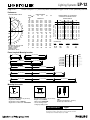
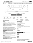
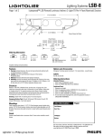
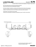
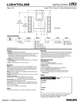
Lighting Systems
1BHFPG
LP-12
-JOFBS1FSG-ZUFÜDN
4FNJ1FSGPSBUFE-JHIU51FS'PPU/PNJOBM
4FDUJPO
5”
(12.70cm)
Perf
3”
(7.62cm)
13” (33.02cm)
98” (248.92cm)
2” (5.08cm)
2” (5.08cm)
2” (5.08cm)
Bottom View
Module Ordering Information
Style
Series
Type
LP
2
B
Lamps
Length
Options
Ballast
3T8
3T8 = 3-F32T8
4 = 4-Foot
8 = 8-Foot
Complete ordering instructions below.
U = Universal Voltage
E = Emergency Pack
D1 = Dimming 120v
D2 = Dimming 277v
Blank = No Options
DS = A-B Switch
X4 = 4 Wire for Dimming &
Switched Emergency
Features
Ordering Information
1. Housing: 18 gauge perforated steel with 51% open hole pattern. Holes are
1/8” (0.32cm) diameter on 5/32” (0.40cm) centers. Die-formed steel end cap
with concealed access holes for through wiring. No exposed fasteners or
hardware.
2. Lamping: Three T8 32 watt fluorescent lamps per 4-foot section. Provided by
others.
3. Reflector: Precision die-formed specular aluminum.
4. Diffuser: Opal acrylic diffuser.
Individual Fixtures:
1. Order number of MODULES required.
2. Order one POWER FEED END SET per MODULE.
Electrical
Ballast is universal voltage, <10% THD, .88 ballast factor, instant start. 3 conductor, 18 gauge wire. Color-coded quick connectors allow ease of connection
for joiner modules. For special circuiting consult factory. Cord is 18/3 SJT. Factory
installed ballast disconnect allows the ballast to be disconnected from and
reconnected to incoming power under load without turning the entire circuit off.
Dimming: 120/277 VAC, 4 wire feed required.
Emergency Battery Pack: 32 watt: 450 lumens @ 90 minutes.
Continuous Rows:
1. Determine run length.
2. Order the appropriate number of MODULES for the complete run.
3. Order one POWER FEED END SET per run.
4. Order one CABLE ASSEMBLY per MODULE minus one per run.
5. For runs that exceed amperage limits, order the appropriate number of SINGLE
CABLE & CORD FEEDS.
Finish
Powder coated baked white enamel. Custom colors available, consult factory.
Labels
UL, cUL and I.B.E.W.
Mountings
Cable Suspension (not shown) - 4-1/2” (11.43cm) diameter flat canopy finished
white enamel, 1/16” (0.16cm) diameter stainless steel aircraft cable adjustable up
to 36” (91.44cm) without cutting. Overlap connector to provide 46” (116.84cm) of
perforated and 2” (5.08cm) solid sections contiguously without the presence of
hairline connections. (See Bottom View drawing above)
Job Information
Type:
Job Name:
Cat. No.:
Options
Dual Switching: Order the DS option for separate row switching. DS option
automatically ships with the X4 option included.
4 Wire: Order X4 modules for remainder of the run when using dimming and/or
switched emergency battery pack modules. Also, order the 4 Wire Cord Power Feed
End Sets (LP2EC36X4) when using 4 Wire Modules.
Emergency Circuiting: Special circuiting - consult factory.
Lamp(s):
Notes:
"JSQPSU3PBE'BMM3JWFS."t
t'BY
We reserve the right to change details of design, materials and finish.
XXXMJHIUPMJFSDPN½1IJMJQT(SPVQt #
Lighting Systems
1BHFPG
LP-12
-JOFBS1FSG-ZUFÜDN
4FNJ1FSGPSBUFE-JHIU51FS'PPU/PNJOBM
4FDUJPO
Performance
ZONE
DEG.
180
175
165
155
145
135
125
115
105
95
90
85
75
65
55
45
35
25
15
5
0
REPORT NO: LRL 200-10B
CAT NO: LP2B3T84U
LAMPS: 3 F32T8
LUMENS: 2900
EFFICIENCY: 85.0%
0
1327
1307
1258
1171
1016
816
656
440
233
70
21
8
26
36
84
98
126
145
159
166
164
CANDLEPOWER
22
45
CANDELAS
1327 1327
1326 1359
1357 1501
1354 1629
1281 1704
1138 1671
1039 1587
851 1240
582
907
226
268
22
33
24
32
32
44
43
57
84
98
99
103
125
129
145
147
157
160
164
166
164
164
67
1327
1427
1590
1794
1943
1911
1796
1342
972
247
36
40
55
67
108
114
134
148
80
165
164
COEFFICIENTS OF UTILIZATION
% EFFECTIVE CEILING CAVITY
REFLECTANCE
90
1327
1395
1620
1873
2055
1991
1807
1430
1004
262
41
44
58
71
108
116
136
150
161
166
164
80
ROOM CAVITY RATIO
CANDLEPOWER CURVE
70
50
WALL REFLECTANCE
70 50 30 70 50 30 50 30
0 82 82 82 71 71 71 50 50
1 75 71 68 65 62 59 44 42
2 68 62 58 59 54 50 38 36
3 62 55 49 53 47 43 34 31
4 57 48 42 49 42 37 30 27
5 52 43 36 45 37 32 27 23
6 47 38 32 41 33 28 24 20
7 44 34 28 38 30 24 21 18
8 40 30 24 35 27 21 19 16
9 37 28 22 32 24 19 17 14
10 35 25 19 30 22 17 16 12
20% FLOOR CAVITY REFLECTANCE
DISTRIBUTION
Lumens
Zone
0-90
508
90-180
6891
0-180
7399
% Lamp
5.8
79.2
85.0
10
50
41
34
28
24
20
17
15
13
12
10
% Luminaire
6.9
93.1
100.0
Fixture Lengths & Mounting Locations
96” (243.84cm)
48” (121.92cm)
4’
4’ 2” (127.00cm)
4-Foot 8-Foot
End Set
Module Module
4-Foot Run
1
1
8-Foot Run
1
1
12-Foot Run
1
1
1
16-Foot Run
2
1
20'-Foot Run
1
2
1
24'-Foot Run
3
1
8’
8’ 2” (248.92cm)
96” (243.84cm)
48” (121.92cm)
12’
12’ 2” (370.84cm)
96” (243.84cm)
16’
96” (243.84cm)
Cable/
Joiner
1
1
2
2
16’ 2” (492.76cm)
96” (243.84cm)
20’
96” (243.84cm)
48” (121.92cm)
20’ 2” (614.68cm)
96” (243.84cm)
24’
96” (243.84cm)
96” (243.84cm)
24’ 2” (736.60cm)
Mounting Accessories
Cable/Joiner Assembly
Standard Cable Length is 36” (91.44cm)
Single Cable: LP2C36
Single Cable & Cord: LP2CC36
Single Cable & 4 Wire Cord: LP2CC36X4
Power Feed End Set
Standard Cable Length is 36” (91.44cm)
Straight Cord: LP2EC36
4 Wire Cord*: LP2EC36X4
* use for dimming and/or
emergency battery packs
Ceiling Grid Kit
CGK
Includes both Standard 1” (2.54cm)
Tee Bar Clip & Slot Tee Clip
Job Information
Type:
"JSQPSU3PBE'BMM3JWFS."t
t'BY
We reserve the right to change details of design, materials and finish.
XXXMJHIUPMJFSDPN½1IJMJQT(SPVQt #