Transcript
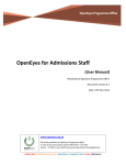
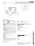
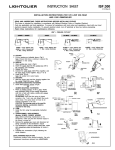
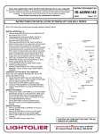
INSTRUCTION SHEET
IS:SL402
12-04/Rev-04
INSTRUCTION FOR INSTALLATION ZYLINDER GLAS
FOR METAL HALIDE PENDANT LUMINAIRE
Read and understand these instructions before installing the luminaire.
CAUTION: Branch circuit conductors must be rated 90°C minimum. To prevent electrical shock turn off electricity and check your
local electrical code and regulations. Consult a qualified electrician before installing.
WARNING: - Risk of fire: Transformer contains luminaire thermal protector. Use only replacement transformer obtained from
Lightolier CFI.
IMPORTANT:
This 39 lb lighting fixture must not to be supported by a junction
box. Provide a 6-in diameter anchor plate with three equal
support points around the junction box. (Fig.4)
FIG.1
A. BALLAST HOUSING:
1. Remove the ballast housing cover with the allen key
provided. (Fig.2)
2. Unfasten the ballast frim the ballast housing. (Fig.3)
3. Feed the power supply wires through the central opening of
the ballast housing. (Fig.4)
4. Rotate the U-brackets as necessary, and attach to the ceiling
with the 3-1/2” long screws (3) provided. (Vig.4)
5. Replace the ballast in the ballast housing. (Fig.3)
B. GLASS/PROTECTOR:
Note: Remove the protective film from the reflector.
1. Push the wires of the lamp housing through the washers with
the frosted side of the glass downward, and with the
polished side of the reflector dome (if applicable) toward the
glass, the washers, the exagonal screws and the pins. (Fig.5)
BALLAST
HOUSING
BALLAST
HOUSING
BALLAST
COVER
ALLEN
KEY
FIG.3
FIG.2
STEM
PINS
WASHERS
REFLECTOR
DOME
BALLAST
HOUSING
WIRES
C. STEM:
1. Align the fastening stem with the U-brackets on the
ballast housing. (Fig.6)
2. Install the threaded bolts over the U-brackets into the
fastening stem with the allen key provided. (Fig.6)
3. Insert the wires into the holes in the U-brackets. (Fig.6)
D. WIRE-IN: (Fig.7)
1. Connect the white (neutral) wire to the white wire of the
ballast.
2. Connect each blue wire of the ballast to each blue wire of
the lamp.
3. Connect the black wire of the ballast to the black wire of the
switch.
4. Connect the power supply wire (120V, 277V or 347V) to the
black wire (switch).
5. Replace the ballast housing cover. (Fig.2)
LAMP:
Remove the clear glass (top). (Fig.8)
Remove the reflector. (Fig.8)
Insert one end of the lamp into the socket and snap in the
other end. (Fig.9)
4. Replace the glass, keeping the nylon washers up against the
glass. (Fig.8)
Note:
- Put back nylon rings on each side of the protective
glass.
- Do not over-tighten the cap nusts as this would cause
unwanted tension.
GLASS
U-BRACKETS
WASHERS
WIRES
SUPPLY
WIRES
LAMP
HOUSING
SCREW
FIG.4
BALLAST
HOUSING
FIG.5
U-BRACKETS
THREADED
BOLTS
ALLEN
KEY
FIL
FASTENING
FIG.7
LAMP
HOUSING
E.
1.
2.
3.
FIG.6
GLASS
REFLECTOR
FIG.8
LAMP
CERAMIC METAL HALIDE
150W T7
DOUBLE ENDED
SOCKET
FIG.9