Transcript
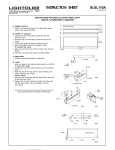
INSTRUCTION SHEET
IS:SL003H
09-04/Rev-01
INSTRUCTION FOR INSTALLATION FOR
KUBIK LIGHT 5 FACE & INVISIBLE CONNECTORS
Read understand these instructions before installing. Turn off electicity at fuse box before proceeding.
Consult a qualified electrician to
ensure that this luminaire is installed with the local
application code. Retain these instructions for
maintenance reference.
5-SIDED
CONNECTOR
SL003H
INVISIBLE
CONNECTOR
SL003G
A. PREPARATION:
1. Remove the cover from the channel.
(See instruction Sheet No.ISSL110A)
2. For flush units No.SL110A and spaced units No.SL110B:
Remove the lampholder housing from the channel.
(See instruction Sheet No.ISSL110A)
B. THREADED CONNECTION:
Invisible connector
1. Insert a threaded connector into the opening of the
channels. (Fig.1)
2. Fasten with the set screw. (Fig.1)
Note: Use the Allen key provided.
3. Push leads through the connector.
4. Align the other channel and secure.
5-sided connector
1. Push the leads through the block, according to desired
configuration. (Fig.2a)
2. Slide connector on leads and screw half the distance
in blocks. (Fig.2b)
3. Secure connectors in the channels. (Fig.3)
HOUSING
ALLEN
KEY
THREADED
CONNECTOR
SET
SCREW
CHANNEL
BLOCK
LEADS
FIG.2a
FIG.1
BLOCK
CONNECTOR
FIG.2b
ALLEN
KEY
LEAD
C. CONNECTING INTO THE CHANNEL:
1. Connect the green or stripped (ground) lead together.
(Fig.4)
2. Connect the white leads together. (Fig.4)
3. Connect the black lead(s) to the blue/white lead. (Fig.4)
4. Reposotion the wire holder as necessary. (Fig.5)
5. Reinstall the cover on the channel.
(See instruction sheet No.ISSL110A)
CHANNELS
SET
SCREW
THREADED
CONNECTOR
D. CEILING or WALL:
Follow the installation instructions on the appropriate instruction sheet. (See series No.ISSL003A, B or C)
FIG.3
E. STEM or CABLE:
Note: The stem or cable can be installed directly onto the
block. (Fig.6)
Follow the installation instructions on the appropriate
instruction sheet. (See series No. ISSL003D or E)
CHANNEL
FIG.4
F. CONNECTION to the JUNCTION BOX:
Follow the installation instructions on the appropriate
instruction sheet. (See series.No.ISSL003)
WIRES
HOLDER
STEM
CABLE
BLOCK
FIG.5
BLOCK
FIG.6