1
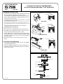
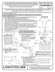
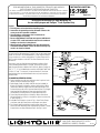
INSTRUCTION SHEET NO.
READ AND UNDERSTAND ALL TRACK, CONNECTOR, FEED-IN-KITS, AND ACCESSORY
INSTRUCTION SHEETS BEFORE INSTALLING ANY TRACK ITEM.
This fixture is intended for installation in accordance with the National Electrical Code and local or Federal
code specifications. To assure full compliance with codes and regulations, check with your local electrical
inspector before installation. To prevent electric shock, turn off electricity at fuse box before proceeding.
Retain these instructions for maintenance reference.
IS:7586
B1197
Page 1 of 2
Installation Instructions for Stem Mounting Kit
for use with Lytespan and ProSpec ™ Track Systems Only.
Caution:
• Turn off power at fuse box before installing track.
• Instructions for grounding must be followed. Failure to do
so may result in a hazardous condition.
• Use only #12 ga. solid copper wire in connectors to
maintain proper track rating.
• Do not supply Advent Track from two separate 120V branch
circuits as this could overload the neutral track conductor
leading to an electrical safety hazard.
• Observe polarity, white (neutral) wire must be connected
to terminal marked "NEUT". Failure to observe Polarity may
result in an electrical hazard.
Stem mounting kits (18" or 48" long) may be attached to the track at
any point and may be spaced up to 4' apart. They may be used to feed
power into the track. The unthreaded end of a stem may be field cut
using a hacksaw or a similar cutting device. The Stem Extension Kits
(48") is used to lengthen a stem 48". The Stem Extension Kit cannot
be field cut.
Instructions show the Stem Mounting Kit being installed on Basic
Track, providing power feed to a Live End. The same instructions
apply to power feed to an Advent Live End, Basic, Advent, ProSpec InLine, "L", "T", "X" or Variable Angle connector and ProSpec Feed Track.
For Basic "X" and "T" connectors, the neutral terminal is the lower
terminal which lines up with the bead in the track, see Instruction
Sheet IS:6165.
A. MOUNTING STEMS TO CEILING
1. Power feed Stem must be stem adjacent to fees in point of track.
(Wires cannot pass beneath two stems).
2. Splice Supply Leads, #12 AWG solid TW wire (not included), to
branch circuit leads in Outlet Box: white to white, black to black
(red to red in Advent). Supply Leads must be long enough to run
horizontally along the track to the track feed-in point. Pass Supply
Leads through Stem Mounting Plate and connect #12 AWG
Ground Wire to Ground Screw on the Stem Mounting Plate.
3. Fasten Stem Mounting Plate to Outlet Box. Mount other Stem
Mounting Plate(s) to ceiling in a straight line. Space not more than
4' apart. See Fig. 1.
4. Assemble Track Clamps as shown in Fig. 1. Screw Track Clamps
onto Stems and slip Screw Collars and Canopies onto Stems.
5. Pass Supply Leads through Stem used for power feed, insert
Stems into Stem Mounting Plates and tighten Set Screws. Thread
Screw Collars onto Stem Mounting Plates. See (Fig. 1 and 2).
Outlet Box
Ground Wire
Stem Mounting Plater
Ground Screw
Groung Spring
Canopy
Set Screws
Screw Collar
Stem
Screws
Track Clamps
Supply Leads
X.
4' MA
Fig. 1
Center Barrier
Broken Off
Wireway Cover
Stem
Live End
Screw
Supply
Leads
Bottom Cover
Screw
Track Rib
Track Clamp
Track Unit
Bead
Fig. 2
FALL RIVER, MASSACHUSETTS 02720
MONTREAL, QUEBEC, CANADA
© 1997
INSTRUCTION SHEET NO.
IS:7586
B1197
Installation Instructions for Stem Mounting Kit
for use with Lytespan and ProSpec ™ Track Systems Only.
Page 2 of 2
B. MOUNTING TRACK ONTO STEMS
1. Loosen Screws on Track Clamps. In the stem used for power feed,
the Track Clamps must be positioned as shown in Fig. 2.
Place Track Ribs (Fig. 4) between Track Clamps and side track into
position. Make sure Bead (Basic and Advent only) (Fig. 4) of Track
Units are in line with one another.
2. Run Supply Leads along top of track toward Live End. Loosen screw
in Live End and remove from track.
3. Cut Wireway Cover to distance from Track Clamp to end of Track
Unit. Slide Wireway Cover into track over Supply Leads (Fig. 2 and
4).
For ProSpec Feed track, place wire cover into track before
attaching the stems to the track unit.
4. Remove Bottom Cover from Live End.
5. Break off Barrier in Live End by bending it back and forth (Fig. 3).
6. Pass Supply Leads through barrier opening in Live End. Insert Live
End into Track Unit and tighten Screws (Fig. 2 and 3).
7. Connect Supply Leads to screw terminals as shown in Instruction
Sheet IS:6020, IS:6121, for Advent), or IS:26000, IS:26046, IS:26050
for ProSpec. Ground terminal in Live End is not used when feeding
power from a Stem.
8. Fasten Bottom Cover to Live End. Tighten Screws on all Track
Clamps.
C. Instructions for Stem Extension Kit
1. Screw Coupling to threaded end of Stem (18" or 48" long) supplied
with Stem Mounting Kit (fig. 5).
2. Screw Stem supplied with Stem Extension Kit to Coupling (Fig. 5).
3. Complete installation of Stem Mounted Lytespan Track following
steps in section A and B.
Center Barrier
Track Rib
Wireway Cover
Bead
Basic Track
Sidewall
Track Rib
Live End
Wireway Cover
Individual
Track Unit
Bottom Cover
Screw
Bead
Advent Track
Barrier
Wireway Cover
Track Rib
Barrier
Feed Track
ProSpec Track
Fig. 3
Fig. 4
Stem Mounting
Plate
Set Screws
Canopy
Screw Collar
Coupling
Stem
(Stem Mounting Kit)
Screws
Track Clamps
Fig. 4
© 1997
Supply Leads