1
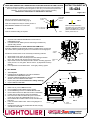
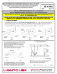
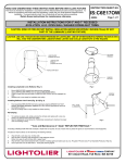
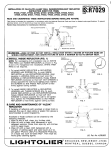
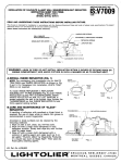
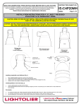
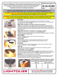
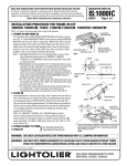
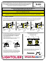
INSTRUCTION SHEET NO. READ AND UNDERSTAND THESE INSTRUCTIONS BEFORE INSTALLING FIXTURE This fixture is intended for installation in accordance with the National Electrical Code and local regulations. To assure full compliance with local codes and regulations, check with your local electrical inspector before installation. To prevent electric shock, turn off electricity at fuse box before proceeding. IS:4X4 Retain these instructions for maintenance reference. Page 1 of 2 B0502 INSTALLATION PROCEDURE FOR: 4X4, 4X9, AND 9X9 MATRIX SERIES RECESSED DOWNLIGHTS. CAUTION: (RISK OF FIRE) DO NOT INSTALL INSULATION ABOVE NOR WITHIN 3 INCHES (76mm) OF ANY PART OF THE LUMINAIRE (FIXTURE) CAUTION: USE ONLY REFLECTOR TRIMS PROVIDED BY LIGHTOLIER. USE OF OTHER MANUFACTURERS’ REFLECTOR TRIMS MAY VOID THE UNDERWRITERS LABRATORIES LISTING AND COULD CONSTITUTE A FIRE HAZARD. A. FRAME-IN AND WIRE-IN Install FRAME-IN KIT (FIK) using ADJUSTABLE MOUNTING BRACKETS (Fig.’s 1-3). Fixture must be secured to structural ceiling members. Connect to supply leads; white fixture lead to neutral (white) supply lead, black fixture lead to hot supply lead, bare copper and/or green insulated wire(s) must be connected to supply ground. Use wirenuts (local hardware items). Place all electrical connections in the J-BOX and close cover. 3/4” OR 1-1/2” CHANNEL (BY OTHERS) 1/2” EMT (11/16” OD) (BY OTHERS) MOUNTING BAR ADJUSTABLE MOUNTING BRACKET ADJUSTMENT SCREW ADJUSTABLE MOUNTING BRACKET FIK. HOUSING FIG. 1 ADJUSTMENT SCREW ADJUSTABLE MOUNTING BRACKET FIK. HOUSING FIG. 2 For suspended T-bar ceilings: T-bar ANCHOR CLIPS accessory No. 1956 (order separately) may be used with 18” or 27” MOUNTING BARS (Fig. 4), or simply wire MOUNTING BARS, EMT TUBING, or CHANNELS to ceiling members (Fig. 5). FIK must be securely attached to and unable to lift from ceiling members after installation is complete. ADJUSTMENT SCREW FIK. HOUSING FIG. 3 MOUNTING BAR ordering information: 18” long: Cat. No. 1950 27” long: Cat. No. 1951 BALLAST NAILS JOISTS WIRE ANCHOR CLIP MOUNTING BAR FIG. 6 T-BAR J-BOX FIG. 4 FIG. 5 For wood joist construction: Mounting bars may be used to secure FIK. to joists (Fig. 6). MOUNTING BARS may be bent where required 90°° to allow precise placement of FIK between joists. Use nails to secure to joists. MOUNTING BAR Note: If FIK is to be used with a WALL-WASH LOUVER TRIM (Fig. 7), FIK must be installed with either J-BOX side or BALLAST side parallel to wall to be washed. Direction of wall to be washed A FIG. 7 COMPANY 631 Airport Road, Fall River, MA 02720 READ AND UNDERSTAND THESE INSTRUCTIONS BEFORE INSTALLING FIXTURE INSTRUCTION SHEET NO. This fixture is intended for installation in accordance with the National Electrical Code and local regulations. To assure full compliance with local codes and regulations, check with your local electrical inspector before installation. To prevent electric shock, turn off electricity at fuse box before proceeding. Retain these instructions for maintenance reference. IS:4X4 Page 2 of 2 B0502 B. ADJUST FIK Set FIK so that bottom edge is flush to, or recessed 1/8” above finished ceiling (Fig. 8). ADJUSTABLE MOUNTING BRACKET ADJUSTMENT SCREWS FIG. 9 FIK Final vertical adjustment may be made by means of ADJUSTMENT SCREWS on inside of FIK. C. CLOSE-IN FLUSH TO CEILING OR UP TO 1/8” RECESSED Close-in and finish ceiling as required. FIG. 8 FINISHED CEILING Base of FIK is provided with a hole pattern (Fig. 9) to assist with the alignment of multiple FIK’s. This hole pattern will facilitate the use of laser beams, plumb lines, etc. D. INSTALLATION OF REFLECTOR TRIM 1. 2. Squeeze both TORSION SPRINGS and insert ends into EMBOSSED SLOTS. Push REFLECTOR TRIM up into FIK until flange is seated firmly against ceiling surface. **Care and Maintenance of “Alzak” REFLECTOR TRIM finish:** If handling of REFLECTOR TRIM with anodized or Alzak finish is required, the use of clean white or plastic film gloves is recommended to avoid fingerprints. TORSION SPRING Anodized or Alzak surfaces can be cleaned by the following methods: 1. 2. 3. 4. EMBOSSED SLOT Wipe off with a soft, clean, dry, lint-free cloth. Wipe off with a soft clean cloth dampened in mild detergent solution. Rinse, then wipe dry with lint-free cloth or paper towel. Wipe off with a clean cloth dampened with a solution of wetting agent and water (such as 2 oz. Per gallon “Pluronic L62-LF” by Wyandotte Products). Wipe dry. Use a liquid wax such as Glass Wax. Avoid gritty cleaning agents. REFLECTOR TRIM FIG. 10 E. RE-LAMPING 1. 2. 3. 4. 5. Turn off power Pull REFLECTOR TRIM down until ends of TORSION SPRINGS reach EMBOSSED SLOTS. Squeeze TORSION SPRINGS to disengage from EMBOSSED SLOTS, and remove REFLECTOR TRIM. Replace lamp (Do not exceed maximum wattage marking). Replace REFLECTOR TRIM. RELEASE SLOT FIG. 11 NUTS BALLAST PLATE HOUSING F. BALLAST REPLACEMENT 1. 2. 3. 4. 5. 6. 7. 8. 9. Make sure AC power is OFF at fuse-box. Remove REFLECTOR TRIM & lamp(s) (See E.). Undo WINGNUT(s) and remove UPPER REFLECTOR. Remove NUTS that secure BALLAST PLATE to HOUSING. Partially remove BALLAST PLATE from HOUSING. Disconnect wire leads from BALLAST push-in terminals. (Insert pin or paper clip in RELEASE SLOT, Fig. 11) Remove BALLAST from BALLAST PLATE, and install new BALLAST. Insert wire leads into BALLAST. Follow wiring diagram on 90° ° BALLAST. Reattach BALLAST PLATE, UPPER REFLECTOR, lamp(s), and REFLECTOR TRIM. BALLAST PLATE BALLAST FIG. 12 UPPER REFLECTOR WINGNUT A COMPANY 631 Airport Road, Fall River, MA 02720