Transcript
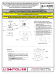
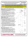
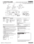
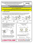
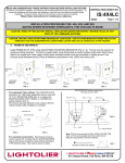
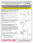
READ
AND
UNDERSTAND
THESE INSTRUCTIONS BEFORE INSTALLING FIXTURE
WIRE GA.
NOTE:
d
This fixture is intended for installation in accordance with the National Electrical Code and local regulations. To
assure full compliance with local codes and regulations, check with your local electrical inspector before
installation. To prevent electric shock, turn off electricity at fuse box before proceeding.
Retain these instructions for maintenance reference.
INSTRUCTION SHEET NO.
IS:C4LVE1RM
Page 1 of 1
B0401
INSTALLATION PROCEDURE FOR: C4LVE1RM & C4LVRMNT REMODELER KITS
WARNING: (RISK OF FIRE) DO NOT INSTALL INSULATION WITHIN 3 INCHES OF FIXTURE SIDES OR WIRING
COMPARTMENT, NOR ABOVE FIXTURE IN SUCH A MANNER SO AS TO ENTRAP HEAT.
WARNING: USE ONLY REFLECTOR TRIMS PROVIDED BY LIGHTOLIER.
USE OF OTHER MANUFACTURES’ REFLECTOR
TRIMS MAY VOID THE UNDERWRITERS LABRATORIES LISTING AND COULD CONSTITUTE A FIRE HAZARD.
STEP ONE:
Use aperture sticker provided as a template and cut a 5" diameter hole in the ceiling.
Cut to outside edge of sticker. Hook the metal frame onto the ceiling and connect supply cable in
the junction box. As shown in FIGURE 1.
STEP TWO: (C4LVE1RM – Remodeler Kit with built in transformer)
FIGURE 1
Wiring: For non-metallic cable, open hinged knockout to allow cable to enter into junction box.
Push cable through clamp. Wire to supply leads. Bare fixture lead and/or green fixture lead to
supply ground. White fixture lead to neutral supply lead. Black fixture lead to hot supply lead. Use
wirenuts (local hardware item). Place all electrical connections in the junction box and close the
junction box cover.
STEP TWO: (C4LVRMNT – Remodeler Kit - No transformer supplied)
Caution: Wiring for 12V supply connection ONLY. (See NOTE below)
Connect bare fixture lead to supply ground. Black and white fixture leads to 12V supply.
Use wirenuts (local hardware item).
STEP THREE:
Install the metal frame through the hole and pull the frame strap down.
As shown in FIGURE 2 & 3.
FIGURE 2
STEP FOUR:
Insert the housing straight up into frame opening while pulling down on the frame
strap. Once housing is flush to ceiling, bend frame strap into housing to secure.
As shown in FIGURE 3 & 4.
STEP FIVE:
Push both ceiling retention clips outward to engage into track, then pull clips down until they
contact the metal frame. As shown in FIGURE 4.
STEP SIX:
FIGURE 3
Tighten both the fine adjustment screws located at the top of the housing tracks until the
assembly is secure. As shown in FIGURE 5.
STEP SEVEN: (Trim Installation)
Insert socket connector into housing connector. Assemble socket and lamp to trim and insert
reflector trim into fixture housing, as shown in FIGURE 6. Push straight up until flush with ceiling.
See separate instructions supplied with trim for complete installation and removal of trim.
REMOVAL: (For access to junction box and transformer).
FIGURE 4
With trim removed, loosen adjustment screws at top of tracks. Pull frame strap down. Squeeze
the vertical side tabs on clips together, and push clip up to top of track while pulling down on
frame strap. When clips are loose, pull housing straight down.
NOTE: (C4LVRMNT ONLY) Follow the max. wire length
recommended below to minimize voltage drop. Voltage
drop will affect the brightness and color of the light.
WIRE LENGTH (FT.)
WIRE GA.
FIGURE 5
FIGURE 6
11
17
28
45
18
16
14
12
A
COMPANY
631 Airport Road, Fall River, MA 02720