1
OUTDOOR STORAGE
MODEL N° 60018
Co
py
OWNER’S MANUAL
Keep this Identification Number in case you must contact our Customer Service Department.
IMPORTANT! PLEASE READ BEFORE BEGINNING ASSEMBLY
Dear Valued Customer,
We would like to congratulate you on your purchase of a Lifetime© Outdoor Storage Shed! We are
confident that you have made the perfect choice and you will be very pleased with your new storage
solution.
Lifetime© Outdoor Storage is part of the family of products created and manufactured by Lifetime®
Products, Inc. Like all of our products, you can be assured that the quality of your Lifetime Outdoor
Storage Shed is the best in the world! And, we back that quality up by offering the best warranty in the
business – A 10-year warranty that fully covers the Shed!
py
All of our Sheds are built with the highest-quality steel and high-density polyethylene (HDPE) parts. The
design and construction of our steel-reinforced double-Wall Panels is second to none. All of our exposed
steel parts and gables are powder coated and we use high-density polyethylene plastic. What makes
polyethylene so special? It has superior strength and durability, and, it won’t crack or degrade outdoors.
So now that you know the quality you are getting in a Lifetime Outdoor Storage Shed, please take the
time to READ THIS INSTRUCTION MANUAL!
We have taken great care in providing the best possible form of instructions to help you put your new
Outdoor Storage Shed together. Before you get started, PLEASE read the following preparation tips to
help you get started!
We can assure you, your construction experience will be a lot more enjoyable if you do!
Co
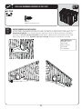
PREPARATION TIPS:
day. Plan to spend a good part of your weekend putting together your fine Outdoor Storage Shed. Our
Lifetime© Outdoor Storage Shed will surely last a long, long time, if you are patient, and take all the time
necessary to put it together as we have instructed.
things go smoother if you have two or more people participating in the construction of the Shed, but it
will go quicker as well. So, the more the merrier!
quired For This Assembly” list on page five of this Owner’s Manual.
damage, we strongly recommend the use of a low-powered power screwdriver or a drill that has an
adjustable clutch that is set on a low-torque setting. If neither is available, use a hand screwdriver. If a
Instruction #1079578 C
8/03/2011
2
IMPORTANT! PLEASE READ BEFORE BEGINNING ASSEMBLY
t#FGPSFCFHJOOJOHBTTFNCMZSFNPWFUIF1BSUT-JTUGSPNUIFDFOUFSPGUIJT0XOFST.BOVBMBOEUBLFBO
inventory of the parts included with your Outdoor Storage Shed. Also, read through the entire instruction manual. It’s always a great practice to get a feel for the flow of the process and to familiarize yourself with the parts involved. But, try not to get ahead of yourself and start the process out of order.
t'0--085)&*/4536$5*0/4*/03%&3&WFSZUIJOHHPFTUPHFUIFSJOBDFSUBJOPSEFSBOEXFIBWF
learned what that correct order should be. In our state-of-the-art research and testing facility, we have
painstakingly created these instructions. The order of construction is there for a reason, and some parts
simply will not fit if built out of order. Just follow along with the order in the instructions and everything
will fit together and things will go very smooth.
t:0634)&%.645#*-50/"-&7&-463'"$&*GUIFTQPUZPVIBWFDIPTFOUPQMBDFZPVS
wonderful new Outdoor Storage Shed is not level, the Shed will not assemble correctly! We recommend
BDPODSFUFQBUJPBXPPEQMBUGPSNPSDSFBUJOHBQBEXJUIQFBHSBWFM:PVS4IFEJTNFBOUUPMBTUBMJGF
time, so provide the proper foundation for it before you start to build.
t#FGPSFZPVCVJMEJUNBLFTVSFZPVBSFBMMPXFEUPCVJMEJU$POTVMUBMMCVJMEJOHDPEFTBTXFMMBTDJUZ
and county ordinances, to ensure that you do not require a building permit to construct your Outdoor
Storage Shed. Proper building permit documentation may be required in your neighborhood, and it
would be quite unfortunate to learn this after your Outdoor Storage Shed is already built!
Now that you’re ready to begin the construction of your wonderful new Outdoor Storage Shed, step
back, take a deep breath, get yourself a large cold beverage and enjoy yourself. We guarantee that after
spending the right amount of time in building your Shed, you will be able to enjoy it for years to come.
Thanks for choosing Lifetime©, and have fun!
ABOUT LIFETIME PRODUCTS, INC.
Lifetime Products, Inc., has applied innovation and cutting-edge technology in plastics and
metals to create a family of affordable lifestyle products that feature superior strength and
durability. The world’s leading manufacturer of folding tables and chairs, Lifetime was founded in 1986 as the maker of portable basketball systems that revolutionized the industry with
patented technology. With diverse offerings such as outdoor storage sheds and steel utility
trailers, Lifetime continues to develop innovative products that outfit the way you live.
Lifetime makes the things you need for the lifestyle you want. By innovating products in and
around the home, Lifetime simplifies your everyday life and enables you to get the most out
of your free time.
3
REGISTER YOUR LIFETIME PRODUCT TODAY!
There are benefits to registering your Lifetime product. With our new online product registration form, it’s fast and easy! Register with us at www.lifetime.com
and enjoy these great benefits:
t3FDFJWFFYDMVTJWFNPOFZTBWJOHPGGFSTGSPN#VZ-JGFUJNFDPNPVSPOMJOFTUPSFBTXFMMBT/&8QSPEVDUOPUJmDBUJPOTBOETQFDJBMDMPTFPVU
promotions!
t*OUIFVOMJLFMZFWFOUPGBQSPEVDUSFDBMMPSTBGFUZNPEJmDBUJPOXFXJMMOPUJGZZPV
t3FHJTUFSJOHZPVSQSPEVDUHVBSBOUFFTZPVXBSSBOUZTFSWJDF*GZPVEPOPUSFHJTUFSZPVSQSPEVDUZPVSXBSSBOUZSJHIUTXJMMOPUCFEJNJOJTIFE
But you will need to provide a sales receipt to verify your product purchase date before warranty service will be provided.
LIFETIME’S PROMISE TO YOU:
Maintaining your privacy is our long-standing policy at Lifetime. And you can rest assured that Lifetime will not sell or provide your
personal data to other third parties, or allow them to use your personal data for their own purposes.
We invite you to read our privacy policy at www.lifetime.com
REGISTER today!
**U.S. and Canada customers ONLY**
IF ASSISTANCE IS NEEDED,
DO NOT CONTACT THE STORE!
CALL OUR CUSTOMER SERVICE DEPARTMENT at 1 (800) 225-3865
HOURS: 7:00 a.m. to 5:00 p.m. Monday through Friday (Mountain Standard Time)
**Call, or visit our Web site for Saturday hours**
**For customers outside the U.S. or Canada, please contact the store for assistance.**
SAFETY INSTRUCTIONS
FAILURE TO FOLLOW THESE WARNINGS MAY RESULT IN SERIOUS INJURY OR PROPERTY
DAMAGE AND WILL VOID WARRANTY.
To ensure safety, do not attempt to assemble this product without following the instructions carefully. Check entire box and inside all
packing material for parts and/or additional instruction material. Before beginning assembly, read the instructions and identify parts
using the hardware identifier and parts list in this document. Proper and complete assembly, use and supervision are essential to
reduce the risk of accident or injury.
t%POPUVTFPSTUPSFIPUPCKFDUTTVDIBTHSJMMTCMPXUPSDIFTXFMEJOHFRVJQNFOUFUDOFBSUIFQSPEVDU
t*GVTJOHBMBEEFSEVSJOHBTTFNCMZVTFFYUSFNFDBVUJPO
t5XPDBQBCMFBEVMUTBSFSFRVJSFEGPSBTTFNCMZ*UJTBMTPSFDPNNFOEFEUIBUBUIJSEBEVMUGVODUJPOBTBOJOTUSVDUJPOSFBEFS
Most injuries are caused by misuse and/or not following instructions. Use caution when using this product.
4
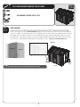
BEFORE BEGINNING ASSEMBLY
Keep the hardware bags and their contents separate. If any parts are missing, call our
Customer Service Department.
3FBEUIFi$POHSBUVMBUJPOTwMFUUFSPOQBHFIdentify and inventory all parts and hardware
using the parts and hardware lists and identifiers in this document.
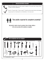
*Two adults required to complete assembly*
Only adults should set up the product. Do not allow children
in the set-up area until assembly is complete.
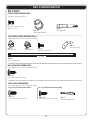
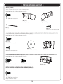
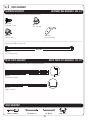
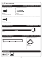
TOOLS REQUIRED FOR THIS ASSEMBLY
7/16"
3/8"
Adjustable
Rubber Mallet
Hammer
Box Knife
Phillips
Plain Screwdriver3/8" Masonry Bit
Screwdriver
2" x 4" x 8'
Leveling Board
Level
(2)
(1)
6’ Ladder
(2)
(1)
(1)
(1)
(1)
(1)
(1)
(1)
Power Drill*
Work Light
Pliers
Flashlight
Hammer Drill*
Safety Glasses
(1)
(1)
(1)
(1)
(1)
(1 for each person)
*See “Screwdriver Notice” on page 7.
5
(1)
(1)
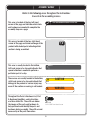
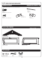
ASSEMBLY GUIDES
Refer to the following areas throughout the instructions
to assist in the assembly process:
This area is located at the top, left-hand
corner of the page and indicates which tools
and hardware are needed to complete the
assembly steps on a page.
TOOLS AND HARDWARE REQUIRED FOR THIS PAGE
SEC
This area is located at the top, right-hand
corner of the page and shows an image of the
product with shaded parts indicating which
section is being assembled.
This area is usually located in the bottom,
left-hand corner of a step and indicates that
special attention is needed to perform a
particular part of a step.
!
These areas are usually located in the bottom,
right-hand corner of a step and indicate that
damage to the product or serious injury may
occur if the caution or warning is not heeded.
Throughout the Parts & Hardware List, Part
& Hardware Identifiers, and instructions
are three-letter IDs. These IDs are below
the images of the parts and hardware to
help you locate and identify the parts and
hardware during assembly. These IDs are not
necessarily on the parts themselves.
#
Note:
CAUTION
WARNING
ADZ (x10)
1/4” x 5/8” Pan-Head Screw
6
IMPORTANT NOTICES
Level Surface Notice:
Surface must be leveled before installation. We recommend building a level work space with a concrete
or patio style surface. If the surface is not properly leveled, the Outdoor Shed will not assemble correctly.
Proper surface leveling will save you time in the long run, so please do not ignore this step.
Building Code Notice:
Consult all local building codes, as well as city and county ordinances, to ensure that the construction of the
Outdoor Shed does not require a building permit. Proper building permit documentation may be required in
your neighborhood, and it would be unfortunate to learn this after constructing the Shed.
Screwdriver Notice:
:PVNBZVTFB1IJMMJQTIFBETDSFXESJWFSCJUBOEBQPXFSTDSFXESJWFSPSESJMMJOTUFBEPGBIBOE
screwdriver. However, be aware that the plastic pieces of your Shed can be damaged by overtightening of
screws. To avoid damage we strongly recommend the use of a low-powered power screwdriver or a drill that
has an adjustable clutch that is set on a low torque setting. If neither is available, use a hand screwdriver. In
any case use caution to avoid overtightening the screws.
Floor Puncture Notice:
Sharp objects may damage your floor. If resting sharp, heavy objects on your Shed floor, place a block of
wood between the sharp object and floor.
CAUTION:
If more than six (6) inches of snow accumulate on the roof of the shed, carefully remove the snow to avoid
possible roof collapse. While standing on the ground, remove the snow from the roof with a broom or snow
shovel. Do not stand on the roof to remove snow.
7
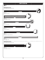
PARTS & HARDWARE LIST
BOX 1
SHED PARTS BOX
ID
"(;
"(0
"('
"()
"(*
"(3
"'9
AFV
"(2
Description
3JHIU%PPS
-FGU%PPS
&OUSZ(BCMF
3FBS(BCMF
3FBS(BCMF
0VUFS'MPPS1BOFM
$FOUFS'MPPS1BOFM
90” Shelf
3PPG1BOFM
ID
Description
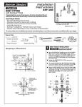
BHC PEGBOARD STRIP INSTALLATION HARDWARE
"%8 Yw1BO)FBE4DSFX
BHD Tool Clip Assortment
"*' w%PVCMF"SN)PPL
"*( w%PVCMF"SN)PPL
"*) +)PPL
"** -)PPL
"*+ 5PPMIPMEFS
BHV GABLE ASSEMBLY HARDWARE (x2)
"(1 -PVWFSFE7FOU
"*2 7FOU4DSFFO
"%8 Yw1BO)FBE4DSFX
"&& Yw'MBU8BTIFS
"%; wYw1BO)FBE4DSFX
")4 w&OE1MVH
ADV
1/4” x 1 1/8” Pan-Head Screw
"$# Yw1BO)FBE4DSFX(Not used)
BEF LEFT DOOR ASSEMBLY HARDWARE
"); -FGU%PPS)BOEMF
"). %FBECPMU-BUDI
"#6 wYw$BSSJBHF#PMU
"%8 Yw1BO)FBE4DSFX
"&& Y'MBU8BTIFS
"%+ w$BQ/VU
AIA
Left Door Lock Bracket
AIB
Left Door Strike Plate
BEG RIGHT DOOR ASSEMBLY HARDWARE
AIK
Right Door Handle
"#7 wYw$BSSJBHF#PMU
"%# wYw4UFFM4QBDFS
""# w$FOUFSMPDL/VU
"): -BUDI4QSJOH
AHW
Latch Block
AIO
Thumb Lever
"%8 Yw1BO)FBE4DSFX
")9 -BUDI$PWFS1MBUF
AHV
Latch, Door
AIL
Right Door Lock Bracket
"&# w'MBU8BTIFS
"&& Yw'MBU8BTIFS
BHZ DOOR & ENTRY GABLE INSTALLATION HARDWARE
"%; wYw1BO)FBE4DSFX
")1 $PUUFS1JO
"*$ -FGU(BQ'MBQ
"*. 3JHIU(BQ'MBQ
"%9 Yw1BO)FBE4DSFX
BHX TRUSS, REAR GABLE, & ROOF INSTALLATION HARDWARE
"%; wYw1BO)FBE4DSFX
"&% w'FOEFS8BTIFS
"%9 Yw1BO)FBE4DSFX
"99 5SVTT)PMF*OTFSU
BEJ WINDOW INSTALLATION HARDWARE
"%; wYw1BO)FBE4DSFX
"*4 8JOEPX-BUDI#SBDLFU
"%: Yw1BO)FBE4DSFX
BHB BATTERY-POWERED LIGHT INSTALLATION HARDWARE (x2)
"%; w9w1BO)FBE4DSFX
Qty
1
CTI METAL PARTS KIT 1
"')
"'(
"'.
"'$
AFE
$3%
5SVTT(VUUFS$IBOOFM
3PPG5SVTT#SBDF
8BMM4IFMG4VQQPSU$IBOOFM
%PPS&OE$IBOOFM
Entry Header Bar
%PPS)JOHF5VCF
1
CTF METAL PARTS KIT 2
"')
5SVTT(VUUFS$IBOOFM
BOX 2
SHED PARTS BOX
"(:
"(/
"(8
"(-
AHD
AHH
"':
$PSOFS8BMM1BOFM
$PSOFS8BMM1BOFM
$PSOFS8BMM1BOFM
$PSOFS8BMM1BOFM
Wall Panel
Window Wall Panel
$FOUFS3PPG$BQ
7
1
BDX SMALL PARTS KIT
"'; AHC
AFL
AHE
"(( AFW
":+ $PSOFS4IFMG
Skylight
Roof Support Strip
Window
'SPOU3PPG$BQ
Rear Roof Cap
#BUUFSZ1PXFSFE-JHIU
4
8
1
1
BSI SMALL PARTS BOX
"*9 8PPE4IJN
AIW
Wood Block
"'6 1FHCPBSE4USJQ
":+ #BUUFSZ1PXFSFE-JHIU
BQH FLOOR ASSEMBLY HARDWARE
#2$
Yw1BO)FBE4DSFX
")0 %PPS)JOHF#VTIJOH
"%$ 1IJMMJQT#JU
BEA TRUSS FRAME ASSEMBLY HARDWARE (x3)
"%+ w$BQ/VU
"%: Yw1BO)FBE4DSFX
"%, $BQ/VU
AIP
Truss Connector
ADH
1/4” Threaded Rod
BHY WALL INSTALLATION HARDWARE
"%; wYw1BO)FBE4DSFX
SHELF INSTALLATION HARDWARE
BHI Corner Shelf Installation Hardware (x6)
"%; wYw1BO)FBE4DSFX
BHH 90” Shelf Installation Hardware
"%; wYw1BO)FBE4DSFX
"*: 4IFMG4VQQPSU#SBDLFU
1
1
1
8
Qty
6
1
1
1
1
1
1
1
1
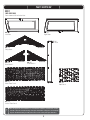
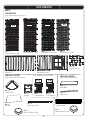
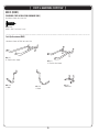
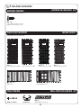
PARTS IDENTIFIER
BOX 1
SHED PARTS BOX
Parts shown at 4% of actual size
AGO (x1)
Left Door
AGZ (x1)
Right Door
AFV (x1)
90” Shelf
(Rear View)
AGF (x1)
&OUSZ(BCMF
AGH (x1)
3FBS(BCMF
(Rear View)
AGI (x1)
3FBS(BCMF
(Rear View)
AGRY
Outer Floor Panel
AGQ (x8)
Roof Panel
AFXY
Center Floor Panel
!
Note: Throughout the Parts & Hardware List, Part & Hardware Identifiers, and instructions are threeletter IDs. These IDs are below the images of the parts and hardware to help you locate and identify
the parts and hardware during assembly. These IDs are not necessarily on the parts themselves.
9
PARTS IDENTIFIER
BOX 1
METAL PARTS KIT [CTI]
Parts shown at 8% of actual size
75 1/2”
AFCY
Door End Channel
51”
AFHY
5SVTT(VUUFS$IBOOFM
59 1/2”
AFE (x1)
Entry Header Bar
48”
AFGY
Roof Truss Brace
67 3/4”
AFMY
Wall/Shelf Support Channel
79 1/2”
CRDY
Door Hinge Tube
METAL PARTS KIT [CTF]
Parts shown at 8% of actual size
51”
AFH (x4)
5SVTT(VUUFS$IBOOFM
10
PARTS IDENTIFIER
BOX 2
SHED PARTS BOX
Parts shown at 4% of actual size
105
104
AGY (x1)
Corner Wall Panel 104
106
AGN (x1)
Corner Wall Panel 105
AGW (x1)
Corner Wall Panel 106
107
AGL (x1)
Corner Wall Panel 107
AFYY
Center Roof Cap
AHH (x1)
Window Wall Panel
AHD (x7)
Wall Panel
SMALL PARTS KIT [BDX]
Parts shown at 4% of actual size
Parts shown at 8% of actual size
116
115
SMALL PARTS BOX [BIA]
Parts are not shown to scale
AIW (x1)
Wood Block
AFZ (x6)
Corner Shelf
AHC (x4)
Skylight
AHE (x1)
Window
AGG (x1)
Front Roof Cap
AFW (x1)
Rear Roof Cap
AIX (x4)
Wood Shim
AFUY
Pegboard Strip
AFL (x8)
Roof Support Strip
AYJ (x1)
Battery-Powered Light
AYJ (x1)
Battery-Powered Light
11
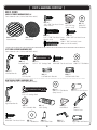
PARTS & HARDWARE IDENTIFIER
BOX 2 (CONT.)
FLOOR ASSEMBLY HARDWARE [BQH]
Hardware shown at actual size
BQCY
Yw1BO)FBE4DSFX
0OMZVTFE
AHOY
Door Hinge Bushing
ADC (x1)
1IJMMJQT#JU
TRUSS FRAME ASSEMBLY HARDWARE [BEA] x3
Parts shown to scale (*Unless otherwise noted)
ADJY
1/4” Cap Nut
ADK (x6)
$BQ/VU
*AIP (x1)
Truss Connector
ADY (x6)
1BO)FBE4DSFX
12 11/16”
*ADH (x1)
1/4” Threaded Rod
WALL INSTALLATION HARDWARE [BHY]
Parts shown to scale (*Unless otherwise noted)
ADZ (x58)
1/4” x 5/8” Pan-Head Screw
SHELF INSTALLATION HARDWARE
Parts shown to scale (*Unless otherwise noted)
Corner Shelf Installation Hardware [BHI] x6
90” Long Shelf Installation Hardware [BHH]
ADZ (x4)
1/4” x 5/8” Pan-Head Screw
ADZ (x14)
1/4” x 5/8” Pan-Head Screw
12
*AIYY
Shelf Support Bracket
PARTS & HARDWARE IDENTIFIER
BOX 2 (CONT.)
GABLE ASSEMBLY HARDWARE [BHV] x2
Parts shown to scale (*Unless otherwise noted)
ADZ (x4)
1/4” x 5/8” Pan-Head Screw
(Only 4 used)
*AIQ (x1)
Vent Screen
*AGP (x1)
Louvered Vent
AHSY
w&OE1MVH
0OMZVTFE
AEE (x5)
Yw
Flat Washer
ADV (x6)
ADW (x5)
1/4” x 1 1/8” Pan-Head Screw Yw1BO)FBE4DSFX
(Only 6 used)
ACB (x1)
Yw1BO)FBE4DSFX
(Not used in this model)
LEFT DOOR ASSEMBLY HARDWARE [BEF]
Parts shown to scale (*Unless otherwise noted)
*AHMY
Deadbolt Latch
*AHZ (x1)
Left Door Handle
ABUY
wYw$BSSJBHF#PMU
ADJY
1/4” Cap Nut
ADWY
Yw1BO)FBE4DSFX
*AIA (x1)
Left Door Lock Bracket
AEEY
Yw'MBU8BTIFS
*AIB (x1)
Left Door Strike Plate
RIGHT DOOR ASSEMBLY HARDWARE [BEG]
Parts shown to scale (*Unless otherwise noted)
AEE (x5)
Yw'MBU8BTIFS
0OMZVTFE
ABVY
wYw$BSSJBHF#PMU
ADBY
wYw4UFFM4QBDFS
*AIK (x1)
Right Door Handle
AABY
1/4” Centerlock Nut
ADW (x4)
Yw1BO)FBE4DSFX
AEBY
1/4” Flat Washer
AHY (x1)
Latch Spring
*AHX (x1)
Latch Cover Plate
13
*AHW (x1)
Latch Block
*AHV (x1)
Door Latch
*AIO (x1)
Thumb Lever
*AIL (x1)
Right Door Lock Bracket
PARTS & HARDWARE IDENTIFIER
BOX 2 (CONT.)
DOOR & FRONT GABLE INSTALLATION HARDWARE [BHZ]
Parts shown to scale (*Unless otherwise noted)
ADZ (x6)
1/4” x 5/8” Pan-Head Screw
*AIM (x1)
3JHIU(BQ'MBQ
*AIC (x1)
-FGU(BQ'MBQ
AHPY
Cotter Pin
ADX (x4)
Yw1BO)FBE4DSFX
TRUSS, REAR GABLE, & ROOF INSTALLATION HARDWARE [BHX]
Parts shown to scale (*Unless otherwise noted)
ADZY
1/4” x 5/8” Pan-Head Screw
AEDY
Yw'FOEFS8BTIFS
ADXY
Yw1BO)FBE4DSFX
*AXXY
Truss Hole Insert
WINDOW INSTALLATION HARDWARE [BEJ]
Parts shown to scale (*Unless otherwise noted)
ADZ (x4)
1/4” x 5/8” Pan-Head Screw
ADY (x1)
Yw1BO)FBE4DSFX
BATTERY-POWERED LIGHT INSTALLATION HARDWARE [BHB] (x2)
Hardware shown at actual size
ADZY
1/4” x 5/8” Pan-Head Screw
0OMZTDSFXTBSFVTFE
14
*AISY
Window Latch
PARTS & HARDWARE IDENTIFIER
BOX 2 (CONT.)
PEGBOARD STRIP INSTALLATION HARDWARE [BHC]
Hardware shown at actual size
ADW (x10)
wYw1BO)FBE4DSFX
Tool Clip Assortment [BHD]
Hardware shown at 50% of actual size
AIG (x1)
4” Double-Arm Hook
AIF (x1)
w%PVCMF"SN)PPL
AIHY
J-Hook
AIJY
Toolholder
AIIY
L-Hook
15
SEC
TOOLS AND HARDWARE REQUIRED FOR THIS PAGE
Concrete (1 cu. yd.)
SEC
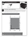
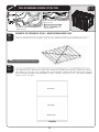
SITE PREPARATION - CONCRETE PLATFORM PREPARATION
1.1
The actual dimensions of your shed (at its widest and longest points) are 8’ x 10’. Ensure you select a site that
will accommodate these measurements. The base of the shed is slightly smaller than this, so you will need to
DSFBUFBMFWFMTVSGBDFUIBUJTBUMFBTUwYw8FSFDPNNFOEVTJOHBMFWFMDFNFOUPSQBUJPTUZMF
surface. This will provide the best long-term performance for your shed.
!
Note: Shed Extension Kits are available for this shed. Please consider possible shed expansion when
planning the site for your shed. See back cover of this manual for information on ordering accessories.
8’
10’
118 1/4”
10’
93 1/2”
8’
Front End
!
Note: Surface must be leveled before installation. If the surface is not properly leveled, the Outdoor Shed will not assemble
or function correctly. Proper surface leveling will save you time in the long run, so please do not ignore this step.
!
Note: Any platform or similar structure should be built above ground in order to avoid water pooling inside the Shed.
16
1
1
1
SEC
TOOLS AND HARDWARE REQUIRED FOR THIS PAGE
1
2” x 4” x 118 1/4”Y
/PUJODMVEFE
2” x 4” x 90 1/2” (x9) (Not included)
16d 3” Common NailY
/PUJODMVEFE
SEC
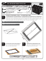
ALTERNATIVE SITE PREPARATION: OPTION 1 - WOOD PLATFORM ASSEMBLY
1.2
&OTVSFBMMMVNCFSVTFEJTUSFBUFEBOEBQQSPWFEGPSPVUEPPSVTF#VJMEPVUTJEFGSBNFUPwYw
outside dimensions:
Note: Whenever possible, you should use the surfaces described on Page
7. When this is not possible, we recommend you use a wood platform or a
filled wood frame.
!
118 1/4”
93
1/2
16”
”
16”
16”
16”
16”
16”
16”
To ensure studs are in the correct location
for nailing plywood in the next step, start
measuring from the corner 16”, and then
measure from center to center.
Fro
nt E
nd
Place the 2” x 4” x 90 1/2” boards on the
inside of the frame. Nail each board in place
with the 16d nails.
!
Note: All lumber must be rated for outdoor use.
!
Note: Surface must be leveled before installation. If the surface is not
properly leveled, the Outdoor Shed will not assemble or function correctly.
Proper surface leveling will save you time in the long run, so please do not
ignore this step.
17
SEC
TOOLS AND HARDWARE REQUIRED FOR THIS PAGE
1
22 1/4” x 93 1/2” x 3/4” Treated Plywood (x1)
(Not included)
48” x 93 1/2” x 3/4” Treated PlywoodY
(Not included)
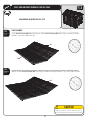
SEC
1.3
8d 1 1/2” Common Nail Y
(Not included)
ALTERNATIVE SITE PREPARATION: OPTION 1 - WOOD PLATFORM ASSEMBLY (CONT)
Square up the frame by measuring from corner to corner. Measurement A should equal Measurement B.
B
A
!
Note: All lumber must be rated for outdoor use.
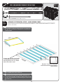
SEC
1.4
Cut Plywood into sizes called for on previous page. Arrange the Plywood according to the diagram and nail into
QMBDFXJUIEYwOBJMT1MBDFQMBUGPSNJOUIFEFTJSFEMPDBUJPO*GQMBUGPSNEPFTOPUSFTUMFWFMPOUIFHSPVOE
CVJMEVQMPXQPJOUTXJUIMPPTFEJSUVOUJMQMBUGPSNJTTUBCMF%SJMMUISFFFWFOMZTQBDFEwESBJOIPMFTJOQMZXPPE
CFUXFFOFBDIwYwKPJTU
48” x 93 1/2”
48” x 93 1/2”
22 1/4” x 93 1/2”
Front End
18
SEC
TOOLS AND HARDWARE REQUIRED FOR THIS PAGE
1
2” x 4” x 120”Y
/PUJODMVEFE
2” x 6” x 89”Y
/PUJODMVEFE
8d 1 1/2” Common Nail (x16)
(Not included)
Pea Gravel (9.8 Cubic Feet) L-Bracket (x4)
(Not included)
(Not included)
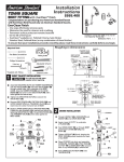
ALTERNATIVE SITE PREPARATION: OPTION 2 - FILLED WOOD FRAME ASSEMBLY
SEC
1.5
Cut outside frame to 8’ x 10’ outside dimensions. Lay boards flat so widest parts face up. Ensure frame is level.
Square up the frame by measuring from corner to corner. Measurement A should equal Measurement B. Nail an
L-Bracket on each corner of the frame with 8d nails. Place platform in the desired location. If platform does not
SFTUMFWFMPOUIFHSPVOECVJMEVQMPXQPJOUTXJUIMPPTFEJSUPSi1FBwHSBWFMVOUJMQMBUGPSNJTTUBCMF
!
Note: Whenever possible you should use the surfaces described on Page 7.
!
Note: All lumber must be rated for outdoor use.
0”
12
B
”
x6
2” ards
Bo
A
”
89
”
96
nd
tE
on
Fr
SEC
1.6
SEC
Once all boards are level and do not wobble,
QBDLi1FBwHSBWFMBSPVOEUIFPVUTJEFPGUIF
frame, and slope away from frame.
1.7
2” x 4” x 8’ Leveling Board (x1)
19
/PXmMMUIFJOTJEFPGUIFGSBNFXJUIi1FBw
gravel. Use a leveling board to scrape off extra
fill material and to level the surface.
SEC
2
FLOOR ASSEMBLY
HARDWARE REQUIRED
HARDWARE BAG REQUIRED: BQH
Hardware shown at actual size
BQCY
Yw1BO)FBE4DSFX
0OMZVTFE
ADC (x1)
1IJMMJQT#JU
AHOY
Door Hinge Bushing
LOCATED IN BOX 1
PLASTIC PARTS REQUIRED
Parts shown at 4% of actual size
AGRY
Outer Floor Panel
AFXY
Center Floor Panel
TOOLS REQUIRED
Phillips Screwdriver
HARDWARE BAG REQUIRED: BQH
Safety Glasses
ADC (x1)
1IJMMJQT#JU
20
SEC
TOOLS AND HARDWARE REQUIRED FOR THIS PAGE
2
NO HARDWARE REQUIRED FOR THIS STEP
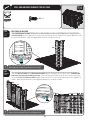
SEC
FLOOR ASSEMBLY
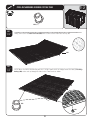
2.1
Lay an Outer Floor Panel (AGR) flat on the ground. Hold a Center Floor Panel (AFX) at an angle as shown and fit tabs
into slots. Lay Center Floor Panel flat.
AFX
AGR
SEC
2.2
Hold the second Center Floor Panel (AFX) at an angle as shown and fit tabs into slots. Lay Center Floor Panel flat.
AFX
CAUTION
Sharp objects may damage your floor. If resting
sharp, heavy objects on your shed floor, place a
block of wood between the sharp object and floor.
21
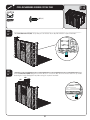
SEC
TOOLS AND HARDWARE REQUIRED FOR THIS PAGE
AHOY
SEC
2.3
Finally, connect the last Outer Floor Panel (AGR) to the second Center Floor Panel and lay flat.
AGR
SEC
2.4
%FDJEFXIJDIFOEXJMMCFUIFGSPOUPGZPVSTIFE-JGUUIF'MPPS1BOFMTVQFOPVHIUPTMJEFUIFUXP
Door Hinge
Bushings (AHO) under and up through the holes in the Floor Panels as shown.
AHO
AHO
22
2
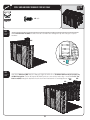
SEC
TOOLS AND HARDWARE REQUIRED FOR THIS PAGE
2
BQCY
0OMZVTFE
SEC
2.5
'BDFUIFTFBNPGUIFUXPBEKBDFOU'MPPS1BOFMT*OTFSUUXP
#8 x 1/2” Pan-Head Screws (BQC) near the seam of a
Floor Panel and down into the tab of the adjacent Floor Panel at the locations shown. Repeat this step for both sides
of each seam as shown.
Insert Screws here.
Seam
Insert Screws here.
23
SEC
TOOLS AND HARDWARE REQUIRED FOR THIS PAGE
2
IF YOU PLAN ON ANCHORING YOUR SHED, CHECK WITH YOUR LOCAL HARDWARE STORE
FOR SUITABLE HARDWARE.
SEC
2.6
ANCHORING THE SHED
If you plan on anchoring your shed, you can anchor it to your platform through the four indentations near the
corners of the floor. The anchoring hardware used depends on the platform. If you have a concrete platform,
XFSFDPNNFOEVTJOHGPVS
w"ODIPS#PMUTBOEGPVS
wYw'MBU8BTIFST*GZPVIBWFBXPPEGSBNFE
QMBUGPSNXFSFDPNNFOEVTJOHGPVS
w-BH#PMUTBOEGPVS
wYw'MBU8BTIFST%POPUFYDFFEB
wEJBNFUFSCPMU3FGFSUPZPVSMPDBMIBSEXBSFTUPSFGPSUIJTIBSEXBSFDo not tighten anchoring hardware until
instructed to do so at the end of these instructions.
8’
10’
WARNING
Failure to anchor the shed may result in property
damage and/or personal injury.
24
SEC
3
TRUSS ASSEMBLY
HARDWARE BAG REQUIRED: BEA (x3)
HARDWARE REQUIRED
Hardware shown at actual size (*Unless noted otherwise)
ADY (x18)
Yw4DSFX
ADJ (x6)
1/4” Cap Nut
ADK (x18)
$BQ/VU
*AIPY
Truss Connector
Part shown at 50% of actual size
12 11/16”
ADHY
1/4” Threaded Rod
METAL PARTS KITS REQUIRED: CTF, CTI
METAL PARTS REQUIRED
Parts shown at 8% of actual size (*Unless indicated otherwise)
51”
AFH (x6)
5SVTT(VUUFS$IBOOFM
48”
AFGY
Roof Truss Brace
TOOLS REQUIRED
Phillips Screwdriver
7/16” WrenchY
3/8” Wrench
25
Safety Glasses
SEC
TOOLS AND HARDWARE REQUIRED FOR THIS PAGE
3/8”
ADY Y
ADK Y
SEC
TRUSS ASSEMBLY
3.1
Stand a Truss Gutter Channel (AFH) upright and set a Truss Connector (AIP) inside the end of the Channel as shown.
Align the holes and secure with one (1) #10 x 3/8” Pan-Head Screw (ADY) and one (1) #10 Cap Nut (ADK).
AIP
AIP
ADY
ADK
AFH
3.2
AFH
Notch
26
3
SEC
TOOLS AND HARDWARE REQUIRED FOR THIS PAGE
3
3/8”
ADY Y
ADK Y
SEC
3.2
Connect another Truss Gutter Channel (AFH) to the Truss Connector using one (1) #10 x 3/8” Pan-Head Screw (ADY) and
one (1) #10 Cap Nut (ADK).
Notch
AFH
ADY
3.4
AFH
AFH
AIP
ADK
AFH
Notch
27
SEC
TOOLS AND HARDWARE REQUIRED FOR THIS PAGE
3
3/8”
ADYY
ADKY
SEC
3.3
Lay the Truss Assembly on its side, and align the holes in a Roof Truss Brace (AFG) with those circled on the Truss
(VUUFS$IBOOFMTBTTIPXO
AFG
SEC
3.4
4FDVSFUIF3PPG5SVTT#SBDFUPUIF5SVTT(VUUFS$IBOOFMVTJOHUXP
#10 x 3/8” Pan-Head Screws (ADY)BOEUXP
#10 Cap Nuts (ADK). Repeat this step for the other end of the Roof Truss Brace.
ADK
ADY
ADK
WARNING
!
Do not overtighten the Cap Nut. If the end of
the Bolt breaks through the plastic cap, call our
Customer Service Department. Exposed threads
on the end of the Bolt may cause serious injuries.
Note: The Cap Nuts goes on the outside of the Truss.
28
SEC
TOOLS AND HARDWARE REQUIRED FOR THIS PAGE
7/16”Y
ADJ (x6)
12 11/16”
ADHY
/PUUPTDBMF
SEC
3.5
With the Truss Assembly on its side, slide a 1/4” Threaded Rod (ADH) through the Roof Truss Brace and Truss
Connector as shown. Secure the top and bottom of the 1/4” Threaded Rod with a 1/4” Cap Nut (ADJ). Tighten all
hardware. The 1/4” Threaded Rod will still spin freely. Set aside. Repeat this section for the second and third Truss
Assemblies.
ADH
ADJ
ADJ
WARNING
Do not overtighten the Cap Nut.
29
3
SEC
4
WALL PANEL INSTALLATION
HARDWARE BAG REQUIRED: BHY
HARDWARE REQUIRED
Hardware shown at actual size
ADZ (x58)
1/4” x 5/8” Pan-Head Screw
(Not all screws will be used)
PLASTIC PARTS REQUIRED
LOCATED IN BOX 1
Part shown at 4% of actual size
104
AGY (x1)
Corner Wall Panel 104
105
AGN (x1)
Corner Wall Panel 105
AHD (x7)
Wall Panel
106
AGW (x1)
Corner Wall Panel 106
AGL (x1)
Corner Wall Panel 107
AHH (x1)
Window Wall Panel
TOOLS REQUIRED
Phillips Screwdriver
107
SMALL PARTS BOX REQUIRED: BSI
Safety Glasses
AIW (x1)
Wood Block (Included)
30
SEC
TOOLS AND HARDWARE REQUIRED FOR THIS PAGE
4
ADZY
AIW (x1)
SEC
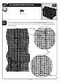
WALL PANEL INSTALLATION
4.1
Fold Corner Wall Panel 105 (AGN). Fit tabs of Panel into the front, left corner of your Floor (while facing shed). Place
a Wood Block (AIW) under the floor panel, directly under the first tab, then pull down on the Corner Wall Panel until
the tab snaps into place. Move the Wood Block under the next tab and repeat.
AGN
AIW
Note: Place the Wood Block (AIW) directly under the tabs as you insert
them throughout the assembly. Snap tabs into place one at a time.
!
SEC
4.2
AHD
Snap two Wall Panels (AHD) and a Window Wall Panel (AHH) into place along the left side of the shed. The Window Wall
Panel may be inserted in any side Wall Panel position. Ensure the tops of the Wall Panels are even and the holes align.
Insert a 1/4” x 5/8” Pan-Head Screw (ADZ) through the top hole of each set of Panels to fasten the Panels together as
TIPXO:PVMMmOJTIGBTUFOJOHUIFQBOFMTUPHFUIFSUPXBSETUIFFOEPGUIJTTFDUJPO
AHH
AHD
AIW
ADZ
!
Note: A second person should apply pressure on opposite side of the Wall
Panels for easier insertion of the Screw. Do not overtighten Screw.
31
SEC
TOOLS AND HARDWARE REQUIRED FOR THIS PAGE
ADZY
AIW (x1)
SEC
4.3
Fold Corner Wall Panel 107 (AGL). Snap into place and fasten at the top hole with the required hardware.
AGL
AIW
SEC
4.4
Insert two Wall Panels (AHD) along the back side of shed. Ensure the tops are level and the holes line up before
fastening the Panels through the top holes using the required hardware.
AHD
AHD
AIW
32
4
SEC
TOOLS AND HARDWARE REQUIRED FOR THIS PAGE
ADZ (x4)
AIW (x1)
SEC
4.5
Fold Corner Wall Panel 106 (AGW) and fasten it to the rear Wall Panel through the top hole using the required
hardware.
AGW
AIW
SEC
4.6
Snap three Wall Panels (AHD) into place along the right side of the shed. The Window Wall Panel may be inserted in any
side Wall Panel position. Ensure the tops of the Wall Panels are even and the holes align. Insert a 1/4” x 5/8” PanHead Screw (ADZ) through the top hole of each set of Panels to fasten the Panels together as shown.
AHD
AHD
AHD
33
4
SEC
TOOLS AND HARDWARE REQUIRED FOR THIS PAGE
ADZ (x45)
AIW (x1)
SEC
4.7
Fold Corner Wall Panel 104 (AGY) and snap it into place at the right, front corner of the Floor as shown. Fasten it to
the Wall Panel through the top hole using the required hardware. Finish fastening all Panels together with the
rest of the 1/4” x 5/8” Pan-Head Screws (ADZ) for all holes.
AGY
AIW
34
4
SEC
5
LEFT DOOR ASSEMBLY
HARDWARE REQUIRED
HARDWARE BAG REQUIRED: BEF
Hardware shown at actual size
ADWY
Yw1BO)FBE4DSFX
ABUY
wYw$BSSJBHF#PMU
1BSUTIPXOBUPGBDUVBMTJ[F
AHMY
Deadbolt Latch
ADJY
1/4" Cap Nut
AEEY
'MBU8BTIFS
Part shown at 15% of actual size
AIB (x1)
Left Door Strike Plate
AHZ (x1)
Left Door Handle
AIA (x1)
Left Door Lock Bracket
METAL PARTS KITS REQUIRED: CTI
METAL PARTS REQUIRED
Part shown at 8% of actual size
75 1/2”
AFC (x1)
Door End Channel
79 1/2”
CRD (x1)
Door Hinge Tube
LOCATED IN BOX 1
PLASTIC PARTS REQUIRED
Part shown at 4% of actual size
AGO (x1)
Left Door
TOOLS REQUIRED
Phillips Screwdriver
7/16” Wrench
Safety Glasses
35
SEC
TOOLS AND HARDWARE REQUIRED FOR THIS PAGE
AHMY
SEC
LEFT DOOR ASSEMBLY
5.1
Rest the Left Shed Door (AGO) with front side down. Slide a Door Hinge Tube (CRD) through the hole in the Door as
shown.
CRD
AGO
Back of Door
SEC
5.2
Position the Deadbolt Latches (AHM) in the slots at the top and bottom of the Door, then slide the Door End Channel
(AFC) onto the Door as shown.
AFC
AFC
Back of Door
AFC
AHM
AHM
AGO
BOTTOM
TOP
!
AFC
Note: The Door End Channel fits onto Door with the flat side up (facing the Deadbolt Latches).
36
5
SEC
TOOLS AND HARDWARE REQUIRED FOR THIS PAGE
5
7/16”
ABUY
AIB (x1)
ADJY
AIA (x1)
SEC
5.3
Slip the Left Door Strike Plate (AIB) over the Left Shed Door and align the holes.
AIB
!
Note: You may need to nudge the Door End Channel to make these holes line up with the gap in the Door.
SEC
5.4
Attach the Left Door Lock Bracket (AIA) to the Left Door Strike Plate with two 1/4” x 1 1/2” Carriage Bolts (ABU) and two
1/4” Cap Nuts (ADJ).
ADJ
WARNING
AIA
Do not overtighten the Cap Nut. If the end of
the Bolt breaks through the plastic cap, call our
Customer Service Department. Exposed threads
on the end of the Bolt may cause serious injuries.
ABU
37
SEC
TOOLS AND HARDWARE REQUIRED FOR THIS PAGE
5
ADWY
AEEY
SEC
5.5
Attach the Left Door Handle (AHZ)VTJOHUISFF
#10 Flat Washers (AEE)BOEUISFF
#10 x 3/4” Pan-Head Screws (ADW).
ADW
AEE
ADW
AEE
AHZ
38
SEC
6
RIGHT DOOR ASSEMBLY
HARDWARE BAG REQUIRED: BEG
HARDWARE REQUIRED
Hardware shown at actual size
AEE (x5)
'MBU8BTIFS
0OMZBSFVTFE
ABVY
Y$BSSJBHF#PMU
AHY (x1)
Latch Spring
ADBY
wYw4UFFM4QBDFS
AHX (x1)
Latch Cover Plate
AIL (x1)
Right Door Lock Bracket
AIO (x1)
Thumb Lever
AHV (x1)
Door Latch
AEBY
1/4” Flat Washer
ADW (x4)
Y1BO)FBE4DSFX
1BSUTIPXOBUPGBDUVBMTJ[F
METAL PARTS REQUIRED
AABY
1/4” Centerlock Nut
Part shown at 15% of
actual size
Part shown at 50%
of actual size
AIK (x1)
Right Door Handle
AHW (x1)
Latch Block
METAL PARTS KITS REQUIRED: CTI
Part shown at 8% of actual size
75 1/2”
AFC (x1)
Door End Channel
79 1/2”
CRD (x1)
Door Hinge Tube
PLASTIC PARTS REQUIRED
LOCATED IN BOX 1
Part shown at 4% of actual size
AGZ (x1)
Right Door
TOOLS REQUIRED
Phillips Screwdriver
7/16” Wrench
Pliers
39
Safety Glasses
SEC
TOOLS AND HARDWARE REQUIRED FOR THIS PAGE
NO HARDWARE REQUIRED FOR THIS PAGE
SEC
6.1
RIGHT DOOR ASSEMBLY
Rest the Right Shed Door (AGZ) with front side down. Slide a Door Hinge Tube (CRD) through the hole in the Door as
shown.
CRD
Back of Door
AGZ
SEC
6.2
Slide the Door End Channel (AFC) onto the Door as shown.
AFC
AFC
Back of Door
AGZ
40
6
SEC
TOOLS AND HARDWARE REQUIRED FOR THIS PAGE
NO HARDWARE REQUIRED FOR THIS PAGE
SEC
6.3
Fit knobs of Thumb Lever (AIO) into the grooves of Right Door Handle (AIK).
Groove
Knob
AIO
AIK
SEC
6.4
Rotate the Thumb Lever into the Right Door Handle. Slide forward until the knobs fit into the holes in the
Handle.
AIO
Knobs snap
into Holes
AIK
41
6
7/16”
ABVY
SEC
TOOLS AND HARDWARE REQUIRED FOR THIS PAGE
6
ADWY
AEBY
AABY
ADBY
AEEY
SEC
6.5
"UUBDIUIF3JHIU)BOEMF"TTFNCMZUPUIF%PPSVTJOHUISFF
#10 Flat Washers (AEE)BOEUISFF
#10 x 3/4” PanHead Screws (ADW).
AIO
AIK
ADW
AEE
ADW AEE
CAUTION
Do not overtighten. Overtightening may damage
parts and void warranty.
SEC
6.6
Install Handle Latch assembly onto the Right Shed Door using the required hardware.
AHV
ABV
AHV
ADB
AIO
AAB
AHX
!
Note: The Door Latch (AHV) goes on top of the Thumb Lever (AIO).
42
AEB
AIL
SEC
TOOLS AND HARDWARE REQUIRED FOR THIS PAGE
6
AHY (x1)
AHW (x1)
ADW (x1)
SEC
6.7
Line up the hole in the Latch Block (AHW) with the hole in the Thumb Lever and secure with one (1) #10 X 3/4” PanHead Screw (ADW).
8.7
ADW
AHW
Lip
!
Note: The lip of the Latch Block (AHW) fits under the Thumb Lever (AIO).
SEC
6.8
Attach Latch Spring (AHY) to the Door Latch (AHV) and the Latch Cover Plate (AHX). Set the Door aside.
AHV
AHY
AHX
WARNING
!
While performing this step, each person
should use protective eye glasses to help
prevent serious eye injury.
Note: Use pliers to pull spring down and hook into bottom hole.
43
SEC
7
GABLE ASSEMBLY
HARDWARE REQUIRED
HARDWARE BAG REQUIRED: BHV (x2)
Hardware shown at actual size
AEE (x10)
Yw'MBU8BTIFS
ADW (x10)
Yw1BO)FBE4DSFX
ADZ (x8)
1/4” x 5/8” Pan-Head Screw
(Only 4 used)
AHS (x4)
End Plug
0OMZVTFE
ADVY
1/4” x 1 1/8” Pan-Head Screw
(Only 6 used)
ACBY
Yw1BO)FBE4DSFX
(Not used in this model)
Parts shown at 8% of actual size
AGPY
Louvered Vent
AIQY
Vent Screen
METAL PARTS KITS REQUIRED: CTI
METAL PARTS REQUIRED
Part shown at 8% of actual size
59 1/2”
AFE (x1)
Entry Header Bar
PLASTIC PARTS REQUIRED
LOCATED IN BOX 1
Parts shown at 4% of actual size
(Rear View)
AGF (x1)
&OUSZ(BCMF
AGH (x1)
3FBS(BCMF
TOOLS REQUIRED
Phillips Screwdriver
Safety Glasses
44
(Rear View)
AGI (x1)
3FBS(BCMF
(Rear View)
SEC
TOOLS AND HARDWARE REQUIRED FOR THIS PAGE
ADZ (x4)
SEC
REAR GABLE ASSEMBLY
7.1
Lay the edge of Rear Gable 2 (AGI) over Rear Gable 1 (AGH) as shown, and align the four holes.
AGI
AGH
SEC
7.2
$POOFDU3FBS(BCMFT together using four (4) 1/4” x 5/8” Pan-Head Screws (ADZ) as shown.
ADZ
ADZ
!
Note: Only use a hand screwdriver in this step.
45
7
SEC
TOOLS AND HARDWARE REQUIRED FOR THIS PAGE
7
AEE (x5)
ADW (x5)
SEC
7.3
-BZ3FBS(BCMF"TTFNCMZnBUPOUIFHSPVOEPWFSUIFVent Screen (AIQ) and Louvered Vent (AGP). Align the holes in
UIF-PVWFSFE7FOUXJUIUIPTFJOUIF3FBS(BCMF"TTFNCMZ
AIQ
AGP
SEC
7.4
"GUFSBMJHOJOHUIFIPMFTQSFTTEPXOmSNMZPOUIF3FBS(BCMF"TTFNCMZXIJMFJOTFSUJOHUIFmWF
#10 x 3/4” PanHead Screws (ADW) and the five (5) #10 x 1/2” Flat Washers (AEE). Pressing down firmly while inserting the Screws will
help prevent the Vent Screen from twisting. Set aside.
ADW
AEE
!
Note: Only use a hand screwdriver in this step.
46
ADW (x5)
SEC
TOOLS AND HARDWARE REQUIRED FOR THIS PAGE
7
AEE (x5)
SEC
ENTRY GABLE ASSEMBLY
7.5
Lay Entry Gable (AGF) flat on the ground over the Vent Screen (AIQ) and Louvered Vent (AGP) as shown. Align the holes
JOUIF-PVWFSFE7FOUXJUIUIPTFJOUIF&OUSZ(BCMF
AGF
AIQ
AGP
SEC
7.6
"GUFSBMJHOJOHUIFIPMFTQSFTTEPXOmSNMZPOUIF&OUSZ(BCMFXIFOJOTFSUJOHUIFmWF
#10 x 3/4” Pan-Head Screws
(ADW) and the five (5) #10 x 1/2” Flat Washers (AEE). Pressing down firmly while inserting the Screws will help prevent
the Vent Screen from twisting.
ADW
AEE
!
Note: Only use a hand screwdriver in this step.
47
SEC
TOOLS AND HARDWARE REQUIRED FOR THIS PAGE
7
ADV (x6)
AHSY
SEC
7.7
Insert an End Plug (AHS) into each end of Entry Header Bar (AFE).
AHS
AFE
The flat screw holes should
face away from the Entry
Gable.
AHS
The indented, rectangular
hole faces downward, and
is closer to the right side
of the Entry Gable.
!
Note: Only use a hand screwdriver in this step.
SEC
7.8
"UUBDIUIF&OUSZ)FBEFS#BSUPUIF&OUSZ(BCMF"TTFNCMZBOETFDVSFXJUITJY
1/4” x 1 1/8” Pan-Head Screws
(ADV). Set aside.
ADV
ADV
ADV
The flat screw holes should
face away from the Entry
Gable.
ADV
The indented, rectangular
hole faces downward, and
is closer to the right side
of the Entry Gable.
!
Note: Only use a hand screwdriver in this step.
48
SEC
8
DOOR & ENTRY GABLE INSTALLATION
HARDWARE BAG REQUIRED: BHZ
HARDWARE REQUIRED
Hardware shown at actual size (*Unless noted otherwise)
AHPY
Cotter Pin
ADZ (x6)
1/4” x 5/8” Pan-Head Screw
*AIM (x1)
3JHIU(BQ'MBQ
ADX (x4)
Yw1BO)FBE4DSFX
PLASTIC PARTS REQUIRED
FROM SECTIONS 5, 6, & 7
Parts shown at 4% of actual size
Rear View
Entry Gable Assembly
Left Door Assembly
Right Door Assembly
TOOLS REQUIRED
Phillips Screwdriver
Pliers
*AIC (x1)
-FGU(BQ'MBQ
Safety Glasses
49
SEC
TOOLS AND HARDWARE REQUIRED FOR THIS PAGE
8
AHPY
SEC
8.1
DOOR INSTALLATION
Align the hole in the bottom of the Hinge of the Left Door Assembly with the hole in the Door Hinge Bushing on the
Floor of your shed, and insert the Door Hinge Tube into the Door Hinge Bushing.
Left Door Assembly
SEC
8.2
Insert a Cotter Pin (AHP) through the Bushing and Door Hinge. Use a pair of pliers to bend the ends of the Cotter
Pins outward. Repeat these steps for the Right Door Assembly.
AHP
!
!
Note: Ensure that these two holes line up, so
that the Cotter Pin (AHP) can be inserted.
50
Note: Use pliers to bend back the
ends of the Cotter Pin (AHP).
SEC
TOOLS AND HARDWARE REQUIRED FOR THIS PAGE
ADZ (x6)
SEC
8.3
2 ADULTS REQUIRED FOR THE STEPS ON THIS PAGE
ENTRY GABLE INSTALLATION
Slide the two holes in the Entry Gable Assembly down over the Door Hinge Tubes as shown.
SEC
8.4
"MJHOUIFIPMFTJOUIFTJEFTPGUIF&OUSZ(BCMF"TTFNCMZXJUIUIPTFJOUIFUPQTPGUIF$PSOFS8BMM1BOFMTBOE
secure with six (6) 1/4” x 5/8” Pan Head Screws (ADZ) at the locations indicated.
51
8
SEC
TOOLS AND HARDWARE REQUIRED FOR THIS PAGE
8
ADX (x4)
AIC (x1)
(Not to scale)
AIM (x1)
(Not to scale)
SEC
8.5
GAP FLAP INSTALLATION
Attach the RightLeft Gap Flaps (AIMAIC) to the top, right and left corners of the Doors as shown. Before
completely tightening the #10 x 1/2” Pan-Head Screws (ADX)TMJEFUIF(BQ'MBQTVQVOUJMUIFZDPWFSBOZHBQCFUXFFO
UIFUPQTPGUIF%PPSTBOEUIF(BCMF
AIC
AIM
ADX
ADX
52
SEC
9
TRUSS, REAR GABLE, & ROOF INSTALLATION
HARDWARE REQUIRED
HARDWARE BAG REQUIRED: BHX
Hardware shown at actual size (*Unless otherwise noted)
ADZY
1/4” x 5/8” Pan-Head Screw
(Not all screws will be used)
ADXY
Yw1BO)FBE4DSFX
AEDY
Yw'FOEFS8BTIFS
METAL PARTS REQUIRED
AXXY
Truss Hole Insert
SMALL PARTS KIT REQUIRED: BDX
Parts shown at 8% of actual size
AFL (x8)
Roof Support Strip
!
Note: The hole in the Roof Support Strip is for
manufacturing purposes only.
Truss Assembly (x3)
PLASTIC PARTS REQUIRED
LOCATED IN BOX 1 & SMALL PARTS KIT: BDX
Parts shown at 4% of actual size
Parts shown at 8% of actual size
116
115
AFW (x1)
Rear Roof Cap
AGG (x1)
Front Roof Cap
AFYY
Center Roof Cap
*AGQ (x8)
Roof Panel
Rear Gable Assembly
TOOLS REQUIRED
Phillips Screwdriver
Flashlight
Safety Glasses
53
AHC (x4)
Skylight
SEC
TOOLS AND HARDWARE REQUIRED FOR THIS PAGE
9
NO HARDWARE REQUIRED FOR THIS STEP
3 ADULTS REQUIRED FOR STEPS 10.1 - 10.8
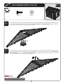
SEC
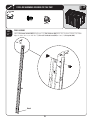
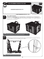
TRUSS & ROOF INSTALLATION
9.1
Place the ends of a Truss Assembly into the notches on the Wall Panels as shown. While one adult holds the Truss
Assembly in place, set a Roof Panel (AGQ) POUPUIF5SVTT"TTFNCMZBOE'SPOU(BCMF5IFFEHFPGUIF3PPG1BOFM
fits down inside the Truss Channel.
AGQ
!
Note: Ensure to carefully read and follow the roof installation instructions and notes. Following each
step in the order listed will minimize potential complications during installation.
SEC
9.2
Ensure the alignment nub in the Roof Panel fits into the notch on the Truss (this helps to align the holes in the
3PPG1BOFMXJUIUIPTFJOUIF5SVTTUIF8BMM1BOFMBOE(BCMF
Alignment Nub
& Notch
Interior Upward View
!
Note: The edge of the Roof Panel fits into the Truss Assembly.
54
SEC
TOOLS AND HARDWARE REQUIRED FOR THIS PAGE
(Not actual size)
9
AFLY
ADZY
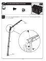
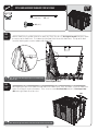
SEC
9.3
8JUIUIF3PPG1BOFMJOQPTJUJPOCFUXFFOUIF(BCMFBOE5SVTTTMJEFPOF
Roof Support Strip (AFL) into place within
the notches of the Roof Panel. The bottom lip of the Roof Panel fits over the Wall Panel. The top of the Wall
Panel fits into the groove near the bottom of the Roof Panel.
AFL
AFL
!
Note: The holes in the Roof Support Strips are for manufacturing
purposes only.
Interior Upward View
SEC
9.4
!
After aligning the holes in the Roof Panel XJUIUIPTFJOUIF8BMM1BOFMT5SVTTBOE(BCMFTFDVSFUIF3PPG1BOFM
to the shed using the required hardware. Then, secure a second Roof Panel (AGQ) and one (1) Roof Support Strip
(AFL) to the right, front side of the shed.
AGQ
Note: Ensure the ridge in the bottom of the Roof Panel fits into the top of the wall.
55
SEC
TOOLS AND HARDWARE REQUIRED FOR THIS PAGE
(Not actual size) AFLY
ADZY
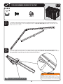
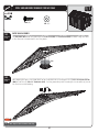
SEC
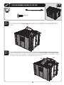
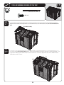
9.5
Place the ends of a second Truss Assembly into the notches on the next Wall Panel and Window Wall Panel as
shown.
SEC
9.6
While one adult holds the Truss Assembly in place, attach two more Roof Panels (AGQ) and Roof Support Strips (AFL)
into the Truss Assemblies as shown. The edge of the Roof Panels fit down inside the Truss Channels. Ensure
the alignment nubs in the Roof Panels fit into the notches on the Trusses.
AGQ
56
AGQ
9
SEC
TOOLS AND HARDWARE REQUIRED FOR THIS PAGE
9
(Not actual size) AFLY
ADZY
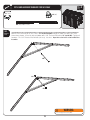
SEC
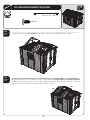
9.3
Place the ends of the last Truss Assembly into the notches on the next set of Wall Panels as shown.
SEC
9.4
While one adult holds the Truss Assembly in place, attach two more Roof Panels (AGQ) and Roof Support Strips (AFL)
into the Truss Assembly as shown. The edge of the Roof Panels fit down inside the Truss Channels. Ensure the
alignment nubs in the Roof Panels fit into the notches on the Trusses.
AGQ
57
AGQ
SEC
TOOLS AND HARDWARE REQUIRED FOR THIS PAGE
9
(Not actual size) AFLY
ADZY
SEC
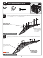
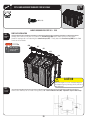
9.7
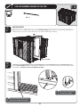
"UUBDIUIF3FBS(BCMF"TTFNCMZUPUIFTIFEBTTIPXOBOETFDVSFXJUIGPVSUFFO
1/4” x 5/8” Pan-Head Screws
(ADZ).
Rear Gable Assembly
SEC
9.8
Secure the last two Roof Panels (AGQ) POUPUIF5SVTTBOE3FBS(BCMF"TTFNCMJFTVTJOHUIFSFRVJSFEIBSEXBSF5IF
edge of the Roof Panels fit down inside the Truss Channels. Ensure the alignment nubs in the Roof Panels fit
into notches on the Trusses.
AGQ
AHB
58
SEC
TOOLS AND HARDWARE REQUIRED FOR THIS PAGE
9
ADZY
2 ADULTS REQUIRED FOR STEP 10.9 - 10.10
SEC
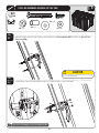
11.9
SEC
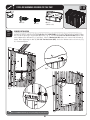
ROOF CAP INSTALLATION
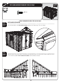
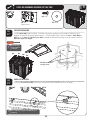
9.9
Starting at the front side of your shed, attach the Front Roof Cap (AGG)UPUIF3PPG1BOFMTBOE&OUSZ(BCMF
Continue moving to the rear attaching the Center Roof Caps (AFY). Finally, attach the Rear Roof Cap (AFW) to the Roof
1BOFMTBOE3FBS(BCMF
AFW
!
Note: Use only a
hand screwdriver
for this step.
AFY
AFY
AFY
AGG
SEC
SEC
11.10
11.11
CAUTION
Only hand tighten screws. Do not overtighten.
Overtightening may damage plastic parts and
void warranty.
SEC
9.10
$POOFDUUIF3PPG$BQTUPFBDIPUIFSVTJOHUXP
1/4” x 5/8” Pan-Head Screws (ADZ). Repeat this step for all Roof Caps.
ADZ
59
ADZ
SEC
TOOLS AND HARDWARE REQUIRED FOR THIS PAGE
ADX Y
AXXY
(Not to scale)
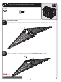
SKYLIGHT INSTALLATION
SEC
SEC
9.11
11.12
!
AED Y
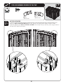
Pre-fold Skylight (AHC) before installing. Push folded Skylight up through opening between Roof Caps; open
Skylight; use tabs to pull Skylight down into place. Fasten Skylight in place with six (6) #10 x 1” Fender Washers
(AED) and six (6) #10 x 1/2” Pan-Head Screws (ADX) (pull down on tabs while inserting screws to provide resistance).
Repeat this step for each Skylight.
AHC
Note: Use only a
hand screwdriver
for this step.
AED
AHC
AHC
AHC
ADX
AHC
Pull down on tabs while
inserting screws.
SEC
11.13
GABLE CLIP INSERTION
SEC
Insert the Truss Hole Inserts (AXX)CFUXFFOUIFSFBS(BCMFBOEUIFSFBS8BMMPGUIF4IFEBTTIPXO
9.12
AXX
AXX
AXX
!
Note: Gable Clip can only be inserted with the arrow
pointing up.
60
9
SEC
10
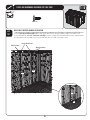
SHELF INSTALLATION
HARDWARE BAG REQUIRED: BHH, BHI (x6)
HARDWARE REQUIRED
Hardware shown at actual size
Parts shown at 15% of actual size
ADZ (x14)
1/4” x 5/8” Pan-Head Screw
AIYY
Shelf Support Bracket
Hardware shown at actual size
ADZY
1/4” x 5/8” Pan-Head Screw
METAL PARTS KIT REQUIRED: CTI
METAL PARTS REQUIRED
Parts shown at 8% of actual size
67 3/4”
AFMY
Wall/Shelf Support Channel
PLASTIC PARTS REQUIRED
LOCATED IN BOX 1 & SMALL PARTS KIT: BDX
Part shown at 4% of actual size
Part shown at 8% of actual size
AFV (x1)
90” Shelf
AFZ (x6)
Corner Shelf
TOOLS REQUIRED
Phillips Screwdriver
Safety Glasses
61
SEC
TOOLS AND HARDWARE REQUIRED FOR THIS PAGE
10
ADZ (x8)
SEC
WALL/SHELF SUPPORT CHANNEL INSTALLATION
10.1
Insert a Shelf Support Channel (AFM) into the slots in the Wall Panels directly below the Right Truss notch, and
secure with four (4) 1/4” x 5/8” Pan-Head Screws (ADZ). Insert a second Shelf Support Channel in the slot directly to
the right of the Left Truss Notch and secure with four (4) 1/4” x 5/8” Pan-Head Screws.
Insert Channels here.
Left Truss Notch
Right Truss Notch
AFM
AFM
ADZ
AFM
ADZ
62
SEC
TOOLS AND HARDWARE REQUIRED FOR THIS PAGE
10
ADZ (x6)
SEC
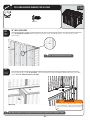
90” SHELF INSTALLATION
10.2
Set a Shelf Support Bracket (AIY) into the slots of each of the Shelf Support Channels. The slots must be at the
same height.
AIY
AIY
!
Note: Insert Shelf Support Bracket at an angle.
SEC
10.3
Fold up flaps on the end of 90” Shelf (AFV). Set Shelf on Brackets with indentations toward wall, and secure with
six (6) 1/4” x 5/8” Phillips Pan-Head Screws (ADZ).
AFV
ADZ
ADZ
ADZ
WARNING
5IFXFJHIUMJNJUGPSBw4IFMGJTMCQFSw
section of Wall Panel. Failure to heed this warning
could result in property damage and/or personal
injury.
Upward view
!
Note: There are only holes for screws along front side of the Shelf (front is labeled “Front” on underside of Shelf).
63
SEC
TOOLS AND HARDWARE REQUIRED FOR THIS PAGE
10
ADZY
SEC
10.4
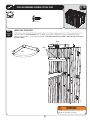
CORNER SHELF INSTALLATION
Fold up edges of a Corner Shelf (AFZ). Line-up holes in the Corner Shelf with a set of pre-made holes in any
Corner Panel as shown. Secure with four (4) 1/4” x 5/8” Phillips Pan-Head Screws (ADZ). Repeat this step for the rest of
the Corner Shelves.
Holes
Holes
AFZ
WARNING
The total weight placed on a Corner Shelf
cannot exceed 10 lb. (4.5 kg).
64
SEC
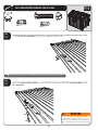
11
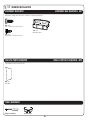
WINDOW INSTALLATION
HARDWARE REQUIRED
HARDWARE BAG REQUIRED: BEJ
Hardware shown at actual size (*Unless indicated otherwise)
ADZ (x4)
1/4” x 5/8” Pan-Head Screw
*AISY
Window Latch
ADY (x1)
Yw1BO)FBE4DSFX
SMALL PARTS KIT REQUIRED: BDX
PLASTIC PARTS REQUIRED
Part shown at 4% of actual size
AHE (x1)
Window
TOOLS REQUIRED
Phillips Screwdriver
Safety Glasses
65
ADZ (x4)
SEC
TOOLS AND HARDWARE REQUIRED FOR THIS PAGE
12
11
AISY
(Not to scale)
ADY (x1)
SEC
WINDOW INSTALLATION
11.1
Remove the plastic protective film from both sides of the Window (AHE) and slide the Window into the grooves along
the sides of the opening in the Window Wall Panel (Fig. 1). Insert the #10 x 3/8” Pan-Head Screw (ADY) into the hole
BUUIFCPUUPNPGUIF8JOEPX'JH
VOUJMnVTI"UUBDIBWindow Latch (AIS) above each corner of the Window as
shown. When tightening the four (4) 1/4” x 5/8” Pan-Head Screws (ADZ), ensure the Window Latches slide freely (Fig.
%POPUPWFSUJHIUFO
ADY
AHE
Fig. 2
ADZ
AIS
Fig. 1
AIS
!
ADZ
Note: Insert Window with bent edge at top and pointing away from the wall.
66
Fig. 3
AIS
ADZ
SEC
12
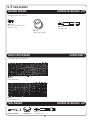
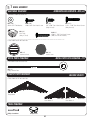
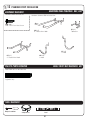
PEGBOARD STRIP INSTALLATION
HARDWARE BAGS REQUIRED: BHC, BHD
HARDWARE REQUIRED
Hardware shown at actual size
Hardware shown at 50% of actual size
ADW (x10)
wYw1BO)FBE4DSFX
AIJY
Toolholder
AIG (x1)
4” Double-Arm Hook
AIIY
L-Hook
AIF (x1)
w%PVCMF"SN)PPL
AIHY
J-Hook
SMALL PARTS BOX REQUIRED: BSI
PLASTIC PARTS REQUIRED
Parts shown at 15% of actual size
AFUY
Pegboard Strip
TOOLS REQUIRED
Phillips Screwdriver
Safety Glasses
Level
67
ADW (x10)
SEC
PEGBOARD STRIP INSTALLATION
12.1
Using a level, position the Pegboard Strip (AFU) in any desired location along a Wall Panel wall. Screw the
Pegboard Strip to the Wall using five (5) #10 x 3/4” Phillips Pan-Head Screws (ADW). See Note. Repeat this step for
second Pegboard Strip.
!
Note: The Pegboard Strip is screwed directly into the plastic. Line up the Strip anywhere on Wall so
holes are over plastic (and not over a groove in the Wall).
AFU
ADW
!
Note: Ensure the Pegboard Strip is level before inserting Screws.
SEC
12.2
Insert Hooks (AIF, AIG, AIH, AII, and AIJ).
68
SEC
TOOLS AND HARDWARE REQUIRED FOR THIS PAGE
12
SEC
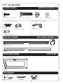
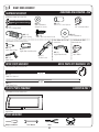
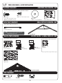
13 FINAL STEPS
HARDWARE REQUIRED
HARDWARE BAG REQUIRED: BHB (x2)
Hardware shown at actual size
ADZ (x6)
1/4” x 5/8” Pan-Head Screw
(Not all Screws are used)
PLASTIC PARTS REQUIRED
SMALL PARTS BOX REQUIRED: BSI
Part not shown an any particular scale
AYJY
Battery-Powered Light
TOOLS REQUIRED
Phillips Screwdriver
Rubber Mallet
SMALL PARTS BOX REQUIRED: BSI
AIX (x4)
Wood Shim (Provided)
Hammer
69
Safety Glasses
SEC
TOOLS AND HARDWARE REQUIRED FOR THIS PAGE
ADZ (x6)
(Not all Screws are used)
SEC
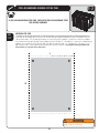
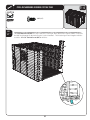
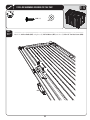
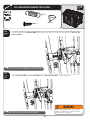
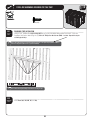
BATTERY POWERED LIGHT INSTALLATION
13.1
Open the battery compartment and remove the plastic cap between the battery and the metal contact. The
Battery Powered Light (AYJ) can be installed above the Right Corner Shelf (on 8'4IFET
PSPOUIF'SPOU(BCMF
*OTFSUUXP
1/4” X 5/8” Pan-Head Screws (ADZ) half-way into the pilot holes on the Corner Wall Panel or Front
(BCMF)BOH-JHIUPO4DSFXTRepeat this step for the second Light. (FOUMZUBQUIFMJHIUUPUVSOJUPOPSPGG
Battery Light Features:
Adjustable Timer
Auto shutoff
Battery powered
Easy on/off
Easy mounting
ADZ
AYJ
ADZ
AYJ
ADZ
ADZ
AYJ
ADZ
70
13
SEC
TOOLS AND HARDWARE REQUIRED FOR THIS PAGE
13
NO HARDWARE PROVIDED FOR THIS STEP
AIX (x4)
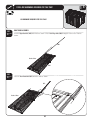
SEC
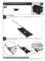
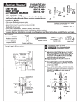
DOOR ALIGNMENT
13.2
In some cases, the shed doors may not completely line up at the tops (fig. 1). When this happens, identify
which side is higher and use a Wooden Shim (AIX) to slightly raise the back corner of the high side until doors line
VQmH
*GEPPSTOFFEGVSUIFSBEKVTUNFOUJOTFSUBOPUIFSTIJNVOEFSUIFGSPOUDPSOFSPQQPTJUFPGUIFmSTUTIJN
If the doors still need further adjustment, stack additional shims (one at a time) alternating between the back
and front shims. After doors are aligned, cut off any portion of wood shim that is still exposed. From inside the
shed, drive a 1” nail through the floor into the shim to hold it in place. Tighten all anchoring hardware now.
High Side
High side
Low side
Fig. 1
Second
Shim
First Shim
!
Note: Shim should be placed at the corner, running directly under one wall.
71
Fig. 2
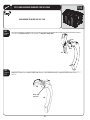
CLEANING & CARE
12
Congratulations on your Lifetime® product purchase. By following the instructions below, your new Lifetime product should
provide you with years of service and enjoyment.
Cleaning and Care
The polyethylene panels are stain- and solvent-resistant. Most stains can be removed, using a mild soap and a soft-bristled
brush. Abrasive cleaning materials may scratch the plastic and are not recommended. Repair scratches or rust spots on
the metal by sanding the affected area lightly; using a rust preventative spray primer; and finally, spraying with a high-gloss
spray enamel paint. Avoid placing a direct heat source on or near surfaces unless using a heat barrier.
72
LIFETIME OUTDOOR SHED EQUIPMENT
10-YEAR LIMITED FACTORY WARRANTY
THE MANUFACTURER RESERVES THE RIGHT TO MAKE SUBSTITUTIONS TO WARRANTY CLAIMS IF PARTS ARE UNAVAILABLE OR OBSOLETE.
1. Lifetime outdoor sheds are warranted to the original purchaser to be free from defects in material or workmanship
GPSBQFSJPEPGUFOZFBSTGSPNUIFEBUFPGPSJHJOBMSFUBJMQVSDIBTF5IFXPSEiEFGFDUTwJTEFmOFEBTJNQFSGFDUJPOTUIBU
impair the use of the product. Defects resulting from misuse, abuse or negligence will void this warranty. This warranty
does not cover defects due to improper installation, alteration or accident. This warranty does not cover damage caused
CZWBOEBMJTNSVTUJOHiBDUTPGOBUVSFwPSBOZPUIFSFWFOUCFZPOEUIFDPOUSPMPGUIFNBOVGBDUVSFS
5IJTXBSSBOUZJTOPOUSBOTGFSBCMFBOEJTFYQSFTTMZMJNJUFEUPUIFSFQBJSPSSFQMBDFNFOUPGEFGFDUJWFQSPEVDU*GUIF
product is defective within the terms of this warranty, Lifetime Products, Inc. will repair or replace defective parts at
no cost to the purchaser. Shipping charges to and from the factory or distribution center are not covered and are the
responsibility of the purchaser. Labor charges and related expenses for removal, installation or replacement of the
shed or its components are not covered under this warranty.
5IJTXBSSBOUZEPFTOPUDPWFSTDSBUDIJOHPSTDVGmOHPGUIFQSPEVDUUIBUNBZSFTVMUGSPNOPSNBMVTBHF*OBEEJUJPO
defects resulting from intentional damage, negligence, unreasonable use or hanging from the truss will void this warranty.
4. Liability for incidental or consequential damages is excluded to the extent permitted by law. While every attempt is
made to embody the highest degree of safety in all equipment, freedom from injury cannot be guaranteed. The user
assumes all risk of injury resulting from the use of this product. All merchandise is sold on this condition, and no
representative of the company may waive or change this policy.
5. This product is not intended for institutional or commercial use; Lifetime Products, Inc. does not assume any liability for
such use. Institutional or commercial use will void the warranty.
6. This warranty is expressly in lieu of all other warranties, expressed or implied, including warranties of merchantability
or fitness for use to extent permitted by Federal and state law. Neither Lifetime Products, Inc., nor any representative
assumes any other liability in connection with this product. This warranty gives you specific legal rights, and you may
also have other rights which vary from state to state.
PLEASE INCLUDE YOUR DATED SALES RECEIPT AND PHOTOGRAPHS OF DAMAGED PARTS.
3&1035130%6$5%&'&$54*/83*5*/(50
Lifetime Products, Inc., PO Box 160010 Clearfield, UT 84016-0010
PSDBMM.'BNUPQN.45
REGISTER YOUR PRODUCT FOR QUICKER CUSTOMER SERVICE.
7JTJUXXXMJGFUJNFDPNPSDBMMUPSFHJTUFSZPVSQSPEVDUUPEBZ
FOR INTERNATIONAL WARRANTY CLAIMS:
All warranty claims must be accompanied by a sales receipt. Report all warranty claims in writing to your regional sales
support representative. Please include your dated sales receipt and photographs of damaged parts.
To Identify the representative for your region — Please visit: www.lifetime.com/international
www.lifetime.com
73
ENHANCE YOUR LIFETIME® PURCHASE BY ADDING ACCESSORIES OR OTHER GREAT PRODUCTS
To purchase accessories or other Lifetime Products, visit us at:
www.lifetime.com
Or call: 1-800-424-3865
74