1
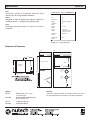
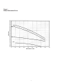
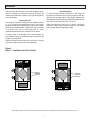
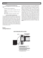
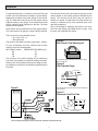
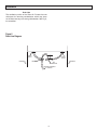
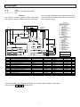
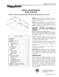
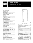
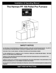
Model 60ELE
“ELECTRIC” CLEAN AIR FURNACE MANUAL
Introduction
Congratulations on your selection of the Lifebreath Clean
Air Furnace. This is a very advanced unit that combines
an electric furnace with the tremendous health benefits of
year-round fresh air ventilation in every room of your
house.
With the addition of Lifebreath T.F.P. Air Cleaner (optional) you will have the ultimate in comfort and healthy indoor
air quality. (See back cover of this manual)
Once it is correctly installed, safety will never be an issue
with your Lifebreath furnace. No flames, fumes or flue
gases to be concerned about.
This Operating and Installation Guide will help you learn
about your Lifebreath Clean Air Furnace quickly and easily. The table of contents will show you where to find
information on every feature of this unit along with easy to
understand operating instructions. If, however, you do
encounter a question that is not covered in this Guide you
should call the Lifebreath dealer who installed your furnace. Chances are that he will be able to give you a
satisfactory answer but if he is unable to do so then we
invite you to contact us directly.
General
The purpose of this manual is to act as an
installation guide only for the Lifebreath Clean Air
Furnace.
All national and local code requirements must be met
when installing a Lifebreath Clean Air Furnace. Be sure to
consult the proper authorities.
Table of Contents
Introduction ......................................................................1
Table of Contents.............................................................1
General ............................................................................1
Specifications................................................................2-4
Installation...................................................................5-10
Wiring Diagram ..............................................................11
Start-up Procedure.........................................................12
Operation .......................................................................13
Troubleshooting .............................................................14
Maintenance and Service Record ..................................15
CAF-03
0606
Specifications
60ELE
Core
Specifications 18kw = (60,000 BTUH)
Ventilation system has patented aluminum heat
recovery core for energy-efficient ventilation.
Voltage
240 VAC 60 Hz
Filters
Hp
1/3
Washable air filters in exhaust and supply air streams of
ventilation section, 1" Pleated in return plenum side.
Amps (total)
85
Stages
Single (4 sequence)
Case
Ventilation
Ducts
6"
Prepainted galvanized steel for superior corrosion resistance.
Return
Plenum
14" x 22"
Supply
Airflow
17.25" x 16"
Ventilation
Airflow
140 CFM
Effectiveness
(HRV)
70%
1350 CFM @ .25 ESP
1180 CFM @ .5 ESP
Note: All connections to be made by qualified contractors.
Net Weight 150 lbs. Shipping Weight 165lbs.
Dimensions & Clearances
Front
Side
12"
16"
Top
Latches
4"
19"
17.25"
6"
*Ventilation
Supply Air
Inlet
6"
*Ventilation
Exhaust Air
Outlet
Duct (coil)
Opening
47.5"
®
CLEAN AIR FURNACE
29.5"
22"
14"
*Return
Plenum
Blower Section
29.5"
Service Clearance 1'
Options
99-186
99-130W
99-122
99-RSK6
19"
Service Clearance 3'
Warranty
Units carry a lifetime warranty on the heat recovery core and a
five year replacement parts warranty on all other components.
Weatherhoods, Two - 6" c/w
1/4" mesh screen
Remote Wall Mount Dehumidistat
Control 24 VAC only,
6” Balancing Damper
6” Backdraft Damper
2
Specifications
60ELE-DF
Core
Specifications 18kw = (60,000 BTUH)
Ventilation system has patented aluminum heat
recovery core for energy-efficient ventilation.
Voltage
240 VAC 60 Hz
Filters
Hp
1/3
Washable air filters in exhaust and supply air streams of
ventilation section, 1" Pleated in return plenum side.
Amps (total)
85
Stages
Single (4 sequence)
Case
Ventilation
Ducts
6"
Prepainted galvanized steel for superior corrosion
resistance.
Return
Plenum
14" x 22"
Supply
Airflow
17.25" x 16"
Ventilation
Airflow
140 CFM
Effectiveness
(HRV)
70%
1350 CFM @ .25 ESP
1180 CFM @ .5 ESP
Note: All connections to be made by qualified contractors.
Net Weight 150 lbs. Shipping Weight 165lbs.
Dimensions & Clearances
Front
Side
Service Clearance 3'
19"
Service Clearance 1'
29.5"
16"
Top
Blower Section
19"
Duct (coil)
Opening
17.25"
14"
*Return
Plenum
22"
®
*Ventilation
Exhaust Air
Outlet
CLEAN AIR FURNACE
47.5"
29.5"
Latches
*Ventilation
Supply Air
Inlet
6"
6"
4"
12"
Options
99-186
99-130W
99-122
99-RSK6
Warranty
Units carry a lifetime warranty on the heat recovery core and a
five year replacement parts warranty on all other components.
Weatherhoods, Two - 6" c/w
1/4" mesh screen
Remote Wall Mount Dehumidistat
Control 24 VAC only,
6” Balancing Damper
6” Backdraft Damper
3
Figure 1
Blower Performance Curve
4
Installation
The purpose of this manual is to give the contractor guidelines for installing the Lifebreath Clean Air Furnace. All
national and local codes relating to this type of equipment
must be followed.
Duct Connections
To accommodate various installations, the Clean Air
Furnace has knockouts for the return air plenum and ventilation ducts, on both sides of the cabinet. Special care
and attention should be given to determining which knockouts are to be removed. (See Fig. 2 & Fig. 3).
Locating The Unit
The Clean Air Furnace is designed to be installed vertically, in a conditioned space,where the surrounding
temperature does not fall below 50°F (10°C). Attic installations are not recommended. Typically the unit is installed
in a mechanical area of the basement, or other
partitioned mechanical room, elsewhere in the home.
Slide Heat Recovery Core out to remove ventilation
knockouts. Never install ductwork directly to the cabinet
that is smaller than the opening provided.
A location close to an outside wall is recommended, as
the ventilation supply and exhaust portion will need to be
ducted to the outside air.
Sufficient clearance around the unit is required for service
of the filter, heat recovery core and components.
Figure 2
Option 1 - Ventilation Ports Off Left Side
Remove
styrofoam
knockout
Remove
styrofoam
knockout
Model 60ELE-DF
Model 60ELE
NOTE: Return plenum opening can be on either side of cabinet and is not dependent on which side the ventilation ports are on.
5
Installation
Figure 3
Option 2 - Ventilation Ports Off Right Side
Remove
styrofoam
knockout
Remove
styrofoam
knockout
Model 60ELE
Model 60ELE-DF
Penetrations from sheet metal screws used to fasten the
ductwork to the cabinet of the unit should only be placed
into the duct flange provided. This is to avoid contact and
damage of the heating/air conditioning coils and internal
wiring.
Locating Intake Weatherhood
The intake weatherhood should be located as follows:
* 4-6' from ventilation exhaust hood, and upstream of
prevailing winds, if possible.
* At least 6' from a dryer vent, oil fill pipes, combustion
outlets, gas meters, garbage containers or anything
else, which may contaminate the air.
Ducting
The duct sizing for the furnace section can be determined
using HRAI Residential Air System Design Manual,
SMACNA, or any other industry-recognized manuals.
* Do not locate fresh air intake in garages, crawl
spaces or attics.
Any ductwork running through unconditioned space must
be sealed properly and insulated to prevent heat loss. All
local codes must be followed in determining the amount of
insulation needed.
* Install 18" above grade, or above expected snow
accumulation.
The ventilation section consists of two 6" (15.2cm) round
ports located on the side of the cabinet, which vent to the
outside. Insulated ducting with a vapour barrier such as
flex-ducting, or ridged pipe wrapped in pipe sleeve, is
required to prevent condensation from occurring on the
pipe. Also the airflow in these lines is designed to be balanced. (See "Balancing Airflows" in this manual, for
damper location and procedure.)
Warning: A backdraft damper is required in the exhaust air
duct to prevent cold air from entering the unit when the
Clean Air Furnace is not running. Fig. D Page 9.
6
Installation
Locating the Exhaust Weatherhoods
The Exhaust Weatherhood should be located as follows:
* At least 4-6' from the supply inlet.
* At least 18" above grade or expected snow accumulation.
* At least 3' from gas meters, combustion vents, or
dryer vents.
* Do not install in garages, crawl spaces or attics.
Outside Ducting the Weatherhoods
The ventilation portion of the Clean Air Furnace can be
vented off either side of the unit by removing knockouts
provided. Once the knockouts in Fig. 2 / Fig. 3 are
removed, a bead of silicone can be placed on the plastic
thermo-collars (provided), to form a seal between the
collars and the cabinet. The collars can then be fastened into place with screws. Note the exhaust outlet is
always the port on the bottom, and the supply inlet is
always the port on the top, both ports should be labeled
from the factory as such.
A small piece of rigid duct (1-2') can be fabricated for
joining the outside ducting to the port collars. (Fig. D,
page 12). This section of pipe is needed to accommodate the balancing damper, as required in the
"Balancing Procedure" in this manual. After installing
the dampers, the small section of pipe can be fastened
to the port collars. The ductwork from the outside
weatherhoods to the unit, is usually flexible ducting,
although rigid pipe may be needed if the runs are
greater than 20 feet. In either case the pipes (both
exhaust and supply and the added fittings) must be
insulated, with a complete vapor barrier Fig. 4. To minimize restriction in airflows the ducting should be short,
with as few bends as possible. See diagram below for
recommended connection of insulated ducting to outside weatherhoods and the Clean Air Furnace port
collars.
Figure 4
Locating Weatherhood
WEATHERHOODINSTALLATION
COLLARISSUPPLIEDTO
ENSUREVAPOURBARRIER
IS100%SEALEDTO
WALLPLATE
SCREEN
(sideview)
12"galvanized
pipesupplied
1/4"(6mm)SCREEN
(frontview)
EXTERIOR
WALL
1. ThermalCollarslidesovergalvanized
sleeveofWeatherhood.
2. FastenThermalCollartoBelt.
3. SlidetheInsulatedFlexibleDuctingover
theWeatherhood'sgalvanizedsleeveand
fastenittotheThermalCollar.
4. Hoodishingedtoallowforeasyaccess
forcleaningofbirdscreen.
7
Installation
Pitot Tube Air Flow Balancing
It is necessary to have balanced air flows in an HRV. The
volume of air brought in from the outside must equal the
volume of air exhausted by the unit. If the air flows are not
properly balanced then:
Balancing Procedure
The following is a method of field balancing an HRV using
a Pitot tube, advantageous in situations when flow stations are not installed in the ductwork. Procedure should
be performed with the HRV on high speed.
*
*
*
*
Choose the straightest section of duct between the HRV
and the weatherhoods. This will be used for both the supply and return ducts.
The HRV may not operate at its maximum efficiency
A negative or positive air pressure may occur in the house
The unit may not defrost properly
Failure to balance the HRV may void warranty
Drill a small hole in the duct (about 3/16"), three feet
downstream of any elbows or bends, and one foot
upstream of any elbows or bends. These are recommended distances but the actual installation may limit the
amount of straight duct.
Prior to balancing, ensure that:
1. All sealing of the ductwork system has been completed.
2. All of the HRV's components are in place and functioning
properly.
3. Balancing dampers are fully open.
4. Unit is on high speed.
5. After taking readings of both the stale air to the HRV duct
and fresh air to the house duct, the duct with the lower
CFM ([L/s] velocity) reading should be left alone, while the
duct with the higher reading should be dampered back to
match the lower reading.
6. Return unit to appropriate fan speed for normal operation.
The Pitot tube should be connected to a magnehelic
gauge or other manometer capable of reading from 0 to
0.25 in. (0 - 62 Pa) of water, preferably to 3 digits of resolution. The tube coming out of the top of the Pitot is
connected to the high pressure side of the gauge. The
tube coming out of the side of the Pitot is connected to the
low pressure or reference side of the gauge.
Insert the Pitot tube into the duct, pointing the tip into the
airflow.
8
Installation
For general balancing it is sufficient to move the Pitot tube
around in the duct and take an average or typical reading.
Repeat this procedure in the other (supply or return) duct.
(Fig. B.). Determine which duct has the highest airflow
(highest reading on the gauge). Then damper that airflow
back to match the lower reading from the duct. The flows
should now be balanced.
The Pitot tube comes with a chart that will give the air flow
velocity based on the velocity pressure indicated by the
gauge. This velocity will be either feet per minute or
metres per second. To determine the actual airflow, the
velocity is multiplied by the cross sectional area of the
duct being measured.
This is an example for determing the airflow in a 6" duct.
The Pitot tube reading was 0.025 inches of water. From
the chart, this is 640 feet per minute.
Actual airflow can be determined from the gauge reading.
The value read on the gauge is called velocity pressure.
The 6" duct has a cross sectional area of:
= (3.14 x [6"÷12]2) ÷ 4
= 0.2 square feet
Figure A:
Pitot Tube Air Flow Balancing Kit
The airflow is then 640 ft./min x 0.2 square feet = 128cfm
For your convenience, the cross sectional area of some
common round duct is listed below:
DUCT DIAM. (inches)
5.0
6.0
7.0
CROSS SECTION AREA (sq. ft.)
.14
.20
.27
The accuracy of the airflow reading will be affected by
how close to any elbows or bends the readings are taken.
Accuracy can be increased by taking an average of multiple readings as outlined in the literature supplied with the
Pitot tube.
c/w magnetic gauge, Pitot tube, hose and carry case.
PART NO. 99-167
Figure B:
Pitot Tube and Gauge
Figure D
Note: For best results, keep Pitot tube well away from dampers and
motor turbulence.
Figure C:
Placement of the Pitot Tube
Pitot Tube
Note: For best results keep Pitot tube
well away from dampers.
*Note: All dampers & fittings must be covered with insulation and sealed with tape
9
Installation
Drain Line
The ventilation portion of the Clean Air Furnace has two
drain pans for removing condensation, which may occur
on the heat recovery core during cold weather. See Fig. 5,
for connection.
Figure 5
Drain Line Diagram
DRAIN
SPOUT
KNOCKOUT
2"
TAPE
TEE
CONNECTOR
THROUGH KNOCKOUT
TO DRAIN
10
DRAIN
SPOUT
KNOCKOUT
Wiring Diagram
R-W
R-G
G-R-Y-C
= Heat
= Fan Only (optional dehumidistat)
= A/C
Electrical
The Clean Air Furnace operates at 240V, single phase
and requires a maximum 100amp fused circuit or breaker.
The low voltage thermostat (not provided) connects to the
R & W terminals for heating and the R & Y & C terminals
when calling for cooling.
IMPORTANT
WIRE IN ACCORDANCE WITH LOCAL AND
CANADIAN ELECTRICAL CODES. READ
CAREFULLY INSTALLATION INSTRUCTION
BEFORE WIRING AND OPERATING.
THERMOSTAT
PDS
240/1
L1
G
N
L2
LEGEND
R
W
G
Y
C
R
W
G
Y
C
A
THR
T
E1..E4
CH
F
PDS
CM
CR
HU
EF
M1
CAP
CG
FILTRE ELECTRONIQUE
HUMIDIFICATEUR
120VAC 60HZ
HU
FI
N
CM
F1
T
24V
240VAC
THR1
THR2
CG
IMPORTANT
SUIVRE LES CODES ELECTRIQUE NATIONAUX
ET LOCAUX AINSI QUE LES INSTRUCTIONS
CONTENUES DANS L'APPAREIL.
N
LÉGENDE
CR
CG
A
F
CR-1
CR-2
15A
HI
6
4
5
CR-3
CH
A
THR1
2
CR-4
3
1
CAP
M2
A
THR1
CM
CH-3
M3
M4
6
CH-4
M7
CODE
SONDE THERMIQUE À RESET
AUTOMATIQUE
THR
RELAIS THERMIQUE
T
TRANSFORMATEUR
E1..E4 ÉLÉMENTS DECHAUFFAGE
ÉLECTRIQUE
CH
RELAIS DE MOTEUR, 2 VITESSES
HU
HUMIDIFICATEUR
EF
FILTRE À AIR ÉLECTRONIQUE
M1
MOTEUR DE VENTILATEUR
PDS
INTÉRRUPTEUR À PRESSION
DIFFERENTIELLE
CM
CONTACTEUR SECONDAIRE
CR
CONTACTEUR DE CLIMATISATION
CAP
CONDENSATEUR
F
FUSIBLE 15 AMP, 250V
CG
RELAIS DE CLIMATISATION
FAN SW
CH-2
LOW
SUPPLY
CIRCUIT
LO
M6
2
A
THR2
ML
5
4
A
THR2
M5
BLOWER
MOTOR
M1
FILTER
M1
AUTOMATIC RESET CUT-OUT
THERMAL RELAY
CONTROL CIRCUIT TRANSFORMER
HEATING ELEMENTS
BLOWER RELAY 2 SPEEDS
FUSE 15 AMPS 250 V
PRESSURE DIFFERENTIAL SWITCH
BACK-UP CONTACTOR
COOLING CONTACTOR
HUMIDIFIER
ELECTRONIC AIR FILTER
BLOWER MOTOR 120VAC
CAPACITOR
COOLING RELAY
CH-1
1
M8
DESCRIPTION
MED
MD
240V/1
18 KW
3
MODEL
MAKE
RATING
FOR MINIMUM SUPPLY
CONNECTION USE 75˚C
COPPER. AWG SIZE
#3
PART #
QTY.
4
1
A
AUTOMATIC RESET CUT-OUT
THERMO DISC
60TX11-312373
25 AMP 277V
CC0 010
F
FAN MOTOR, ELECT. FILTER& HUM. SUPPLY FUSEHOLDER
BUSS
HKP-HH
15 AMP 240V
CFH 015
F
FAN MOTOR, ELECT. FILTER& HUM. SUPPLY FUSE
BUSS
MDL 15
15 AMP 240V
CFU 035
1
THR
4 POLE SEQUENCER
THERMODISC
15S24
25 AMP 240V
CCT 130
1
CR
COOLING FAN RELAY COIL 120V 50/60HZ
HONEYWELL
R4222D1039
15A 277V
DEC 010
1
CH
HEATING FAN RELAY COIL 208/240V 50/60HZ
PRODUCTS UNLIMITED
9100-233U999
15A 277V
CCT 145
1
FAN SW
LOW SPEED CONTINUOUS
CARLINGSWITCH
115A13-2XA
16A 120V
PMC 012
1
T
CONTROL TRANSFORMER
PRODUCT UNLIMITED
4000-09AW18AE887
240V/24V 50VA
CTR 090
1
G
GROUND LUG
ILSCO
TA-6-I
35 AMP
CLG 010
1
R--C
CONTROL TERMINAL BLOCK TO THERMOSTAT
WECO
324-FU-HDS/12
15 AMP 240V
CP1 054
HU--MD
BLOWER MOTOR, ELECT. FILTER& HUM. TERMINAL BLOCK
WECO
324-FU-HDS/12
15 AMP 240V
CPI 056
1
L1..3
POWER TERMINAL 3 POLE
THERMOLEC
3P-PWR-BLK
125 AMPS
CP1 070
1
CG
CONTROL RELAY COIL 24V
STEVECO
134-20102101ZZ
25 AMPS
CCT 139
1
PDS
PRESSURE DIFFERENTIAL SWITCH
CLEVELAND
DFS-221-112
15 AMP 240V
CAF 010
1
*120 Volt terminals are provided for connecting an air filtration device/humidifier. These terminals are labeled HU
F1 N as shown above.
11
Start Up Procedure
In order for any appliance to work properly it must be set
up and tested by a knowledgeable technician.
NOTE: Continuous low speed can be turned ON/OFF
with the ventilation switch, (fig. 6).
The following conditions must be met prior to start-up
NOTE: Continuous high speed can be obtained by
switching thermostat fan switch to manual/on.
1. Blower wheel rotates freely inside its housing.
NOTE: For models with the ECM blower motor. Low
speed fan is controlled by the thermostat fan
switch (R and G terminals).
2. Wiring connections are tight.
3. Water is sitting in the "P" trap below the HRV core.
4. All duct and pipe connections are sealed.
High speed blower operation is obtained by
making a dry contact closure across R and the
Orange wire from the ECM motor.
5. Front access door is on tight.
Once all of the necessary connections have been made,
the Clean Air Furnace Start-Up Procedure is as follows:
1. Turn on power supply to Clean Air Furnace. Caution:
The blower will start running at a lower speed.
NOTE: Downflow models incorporate a flow
switch to verify blower operation and airflow. If airflow is not sensed or the
pressure switch is blocked, the electric
heating elements will NOT start. NEVER
override or disable safety switches. If airflow is blocked or too low, the airflow
MUST be diagnosed and corrected.
2. Switch the room thermostat to heat. The thermostat
should be set higher than the current room temperature
in order to energize the unit and commence the heating
cycle.Verify heat cycle starts.
3. Set room thermostat at desired temperature setting.
4. Switch fan to manual at the thermostat so the unit will
run at high speed in order to perform the balancing procedure on the ventilation section.
Note: For ECM motors, refer to note located on this
page regarding high speed fan operation.
5. After balancing the ventilation according to instructions,
set the thermostats fan switch to "auto". On "auto" the
fan will run continuously at a low speed if the ventilation switch (fig. 6) is in the continuous mode, until
heating or cooling is called for and then will switch to a
higher speed. On "manual" the fan will run at high
speed continuously.
12
Operation
Heating/Cooling
When the room thermostat calls for heat, the furnace
blower switches on to heating speed and will start circulating air across the coil, which picks up heat and
delivers it to the rest of your home.
Ventilation
The heat recovery ventilation (HRV) portion of the Clean
Air Furnace, is automatic. Once set, a desired amount
of fresh air will be drawn into the home while the furnace blower is activated.
Once the thermostat's temperature is reached the elements will shut off, and the blower will return to its
pre-set speed or off.
To reduce humidity increased ventilation may be
required. An optional remote dehumidistat can be
installed. The dehumidistat will increase the speed of
the furnace blower to high and will return to its original
setting when humidity levels decrease. Your dehumidistat must be switched off during warmer months as it is
not required for air conditioning operation. To increase
humidity a quality humidifier should be added to the system.
Note: When the furnace blower is left running on
low speed the air in the home circulates continuously. When the heat is called for the blower will
automatically switch to a higher speed. After the
required hot air has been delivered the blower will
switch back to low speed.
When the thermostat calls for cooling (optional A coil
and condensing unit required) the furnace blower activates to high speed and the outdoor condenser unit is
energized. After the thermostat temperature is reached
the condensing unit will shut off, and the blower will
return to its low speed. Continuous low speed is selectable, (fig. 6).
Typically the air flow for ventilation will be set to 50 70cfm, for low speed furnace operation, and
100 - 150cfm at high speed. The pleated furnace filter
should be checked regularly and replaced as needed.
The HRV filter should be washed twice a year or more
often if needed.
Figure 6
Low speed selection switch (PCS motor models only)
(CONTINUOUS or OFF)
Top
13
Troubleshooting
Lack of heat
1. Check that the room thermostat is set to the desired
temperature.
Humidity levels are too low
1. If you have installed a dehumidistat ensure that its setting is correct.
2. Ensure there is power to the unit.
2. Check humidifier settings.
3. Verify that the airflow in and out of the system matches
designed specs. If airflow is low, check for blockage in
the filter or some other obstruction.
3. Change thermostat fan switch from manual to automatic.
4. Change ventilation switch on furnace from continuous
(low) to automatic.
HRV core freezes up
1. Make sure that the supply and exhaust lines are balanced according to the "Balancing Procedure" in this
manual.
Humidity levels are too high
1. If you have installed a dehumidistat ensure its setting is
correct.
2. If out of balance, ensure that the balancing dampers
have not been moved and that there are no obstructions in the outside hoods.
2. Install a dehumidistat if necessary
3. Change ventilation switch on furnace from automatic to
continuous.
3. If necessary, install optional defrost kit, according to
instructions.
4. Change thermostat fan switch from
automatic to manual.
Water sits in drain pipes
1. Check drain pans or lines for plugs.
2. Confirm that the HRV core is installed according to
manufactures recommendations.
3. Check the drain line for kinks.
4. Make sure that the O-ring in the drain nozzles sit flat.
5. Ensure the drain line has enough "fall" to it.
Condensation/ice forming inside ventilation ducts
A rip in the vapor barrier or poorly sealed joints may
cause condensation or ice to form on the ducting. If this
occurs, replace the entire line.
14
Maintenance and Service Record
Date:
Particulars
15