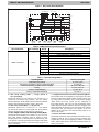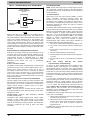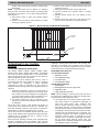
1
SERVICE AND MAINTENANCE INSTRUCTIONS VERTICAL/HORIZONTAL/MULTI−POSITION FAN COIL UNITS FEM4, FCM4, FSA4, FEA4, FSM4, FSU4, FXM4, FVM4, FMA4, WAH, WAP, WAM, WAX, REM4 NOTE: Read the entire instruction manual before starting the installation. TABLE OF CONTENTS PAGE SAFETY CONSIDERATIONS . . . . . . . . . . . . . . . . . . . . . . . . 1 INTRODUCTION . . . . . . . . . . . . . . . . . . . . . . . . . . . . . . . . . . 1 FAN COIL DESCRIPTION AND TROUBLESHOOTING . . 1 FSM4P, FSU4P, FSM4X, FSU4X, FSA4X . . . . . . . . . . . . 1 FEM4P, FEM4X, FXM4X, FEA4X, WAHA, WAPM, WAPT, WAPL, WAHM, WAHT, WAHL, WAXM, WAXT, WAXL, REM4P, REM4X . . . . . . . . . . . . . . . . . . . . 5 Recognize safety information. This is the safety−alert symbol . When you see this symbol on the unit and in instruction manuals, be alert to the potential for personal injury. Understand the signal words DANGER, WARNING, and CAUTION. These words are used with the safety−alert symbol. DANGER identifies the most serious hazards which will result in severe personal injury or death. WARNING signifies hazards which could result in personal injury or death. CAUTION is used to identify unsafe practices which may result in minor personal injury or product and property damage. NOTE is used to highlight suggestions which will result in enhanced installation, reliability, or operation. ! FVM4X . . . . . . . . . . . . . . . . . . . . . . . . . . . . . . . . . . . . . . . . . 6 CAUTION FCM4X . . . . . . . . . . . . . . . . . . . . . . . . . . . . . . . . . . . . . . . . 12 UNIT OPERATION AND SAFETY HAZARD FMA4P, FMA4X, WAMA WAXA . . . . . . . . . . . . . . . . . . . 17 Failure to follow this caution may result in equipment damage, improper operation or personal injury. ELECTRIC HEATER FUNCTION AND TROUBLESHOOTING . . . . . . . . . . . . . . . . . . . . . . . . 21 FEM4, FCM4, FSA4, FEA4, FXM4, FVM4, WAPM, WAPT, WAPL, WAHM, WHAT, WAHL, WAXM, WAXT, WAXL, REM4 . . . . . . . . . . . . . . . . . . . . . . . . . . . . 21 When coils are pressurized with nitrogen, open the suction port first to release the nitrogen. Mesh screens may dislodge if the liquid line is opened first. FMA4, WAMA, WAXA . . . . . . . . . . . . . . . . . . . . . . . . . . . . 21 ! CARE AND MAINTENANCE . . . . . . . . . . . . . . . . . . . . . . . 22 WARNING FEM4P, FEM4X, FCM4X, FXM4X, FVM4X, WAHA, WAPM, WAPT, WAPL, WAHM, WAHT, WAHL, WAXM, WAXT, WAXL, REM4X . . . . . . . . . . . . . . . . . . . . 22 UNIT OPERATION AND SAFERTY HAZARD FSA4X, FEA4X, FMA4P, FMA4X, WAMA, WAXA . . . . 23 R−410A systems operate at higher pressures than R−22 systems. Do not use R−22 service equipment or components on R−410 equipment. Ensure service equipment is rated for R−410A. REFRIGERANT FLOW−CONTROL DEVICE . . . . . . . . . . 24 Thermostatic Expansion Valve (TXV) . . . . . . . . . . . . . . . 24 Piston Body Cleaning and Replacement . . . . . . . . . . . . 25 COIL & CONDENSATE PAN REMOVAL and REPLACEMENT . . . . . . . . . . . . . . . . . . . . . . . . . . . . . . 26 R−410A QUICK REFERENCE GUIDE . . . . . . . . . . . . . . . 28 SAFETY CONSIDERATIONS Improper installation, adjustment, alteration, service, maintenance, or use can cause explosion, fire, electrical shock, or other conditions which may cause death, personal injury or property damage. Consult a qualified installer, service agency, or your distributor or branch for information or assistance. The qualified installer or agency must use factory−authorized kits or accessories when modifying this product. Refer to the individual instructions packaged with kits or accessories when installing. Follow all safety codes. Wear safety glasses, protective clothing and work gloves. Have a fire extinguisher available. Read these instructions thoroughly and follow all warnings or cautions included in literature and attached to the unit. Consult local building codes and the current editions of the National Electrical Code (NEC) NFPA 70. In Canada, refer to the current editions of the Canadian Electrical Code CSA C22.1. Failure to follow this warning could result in personal injury or death. INTRODUCTION These fan coil units are designed for flexibility in a variety of applications that meet upflow, horizontal, or downflow requirements. Units are available in 1−1/2 through 5 ton nominal cooling capacities. Factory−authorized, field−installed electric heater packages are available in 5kW @ 240Vac through 30kW @240Vac. ! WARNING ELECTRICAL OPERATION HAZARD Failure to follow this warning could result in personal injury or death. Before installing or servicing unit, always turn off all power to unit. There may be more than one disconnect switch. Turn off accessory heater power if applicable. Lock out and tag switch with a suitable warning label. Specifications subject to change without notice. 496 08 8001 01 4/2/2014 SERVICE AND MAINTENANCE FAN COILS FAN COIL DESCRIPTION AND TROUBLESHOOTING PSC FAN MOTOR FSM4, FSU4, FSA4 The PSC motor is two or three speed direct drive. High−speed lead is black, low−speed lead is red, and common lead is yellow. Be sure proper blower speed has been selected.. The motor is turned on through two different routes. The first occurs when thermostat calls for the fan in cooling, heat pump, or fan−only mode. A 24−Vac signal is sent to relay, causing relay to close its normally open contacts, turning fan on. The second occurs when there is a call for electric heat. A 24−Vac signal is sent to heater sequencer/relay, causing it to close, directing 230V through the normally closed contact of fan relay, turning fan on. The fan remains on until sequencer/relay opens. If motor does not run, test motor for an open winding or a winding shorted to motor case. If either is present, replace motor. ELECTRIC HEATER SERVICE Service can be completed with heater in place. Shut off power before servicing. A. Limit Switch Refer to Electric Heater Function and Troubleshooting section of this manual. B. Sequencer Refer to Electric Heater Function and Troubleshooting section of this manual. C. Transformer A 40−VA transformer supplies 24−V power for control circuit. Check for 208/230V on primary side of transformer. If present, check for 24V on secondary side. NOTE: Transformer is fused. Do not short circuit. D. Fan Relay Relay coil is 24−V. Check for proper control voltage. Replace relay if faulty. CLEANING OR REPLACING REFRIGERANT FLOW−CONTROL DEVICE Refer to Figure 19 and instructions given in “Piston Body Cleaning or Replacement” section. The refrigerant flow−control device is protected by a wire mesh strainer. It is located inside the 3/8−in. liquid tube at field braze joint next to flow−control device. Access to strainer is through field braze joint. SEQUENCE OF OPERATION A. Condensing Unit COOLING When thermostat calls for cooling, the circuit between R and G is complete and single−pole single−throw relay FR is energized. The normally open contacts close causing blower to operate. The circuit between R and Y is also complete. This completed circuit causes contactor in outdoor unit to close which starts compressor and outdoor fan. HEATING When thermostat calls for heating and FAN switch is set on AUTO, the circuit between R and W is complete. The heater sequence SEQ is energized which closes contacts of relay. 2 There will be a time delay. This completed circuit energizes all heating elements HTR and blower motor. B. Heat Pump COOLING On a call for cooling, the thermostat makes circuits R−O, R−Y, and R−G. Circuit R−O energizes reversing valve, switching it to cooling position. Circuit R−Y energizes contactor starting outdoor fan motor and compressor. Circuit R−G energizes indoor unit blower relay starting indoor blower motor. When thermostat is satisfied, its contacts open de−energizing contactor reversing valve and blower relay. This stops compressor and fan motors. HEATING On a call for heating, the thermostat makes circuits R−Y and R−G. Circuit R−Y energizes contactor starting outdoor fan motor and compressor. Circuit R−G energizes indoor blower relay starting blower motor. Should temperature continue to fall, R−W circuit is made through second−stage room thermostat bulb. Circuit R−W energizes a sequencer bringing on supplemental electric heat. When thermostat is satisfied, its contacts open de−energizing contactor and sequencer. All heaters and motors should stop. Control Board (contact FAST for part number) This section of the service manual describes the PCB by examining the functional operation of the PCB components. Printed Circuit Board (PCB) Component Layout of the actual PCB is depicted in Figure 1. 1. The low−voltage stripped leads are used to connect the 24−V side of transformer to indoor thermostat and outdoor section. 2. A 5−amp fuse is used to protect the low−voltage transformer secondary. 3. The fan relay is controlled by thermostat and turns fan on and off. 4. A plug is used as the connection for PCB power and electric heaters. Note the pin numbers on plug. 5. A time−delay relay circuit keeps fan motor running for approximately 90 seconds after G is de−energized. The time−delay can be defeated by cutting jumper JW1. Unit Functions A. Transformer 1. Proper Wiring of Transformer Primary or High Side Yellow wire from Molex plug is wired to C terminal on transformer and black wire from PCB relay (normally−open) terminal is wired to 208−V or 230−V terminal on transformer. Units are factory wired at 230−V terminal. 2. Proper Wiring of Transformer Secondary or 24−V Side Red wire of transformer is wired to T terminal on PCB and brown wire of transformer is wired to C terminal on PCB. NOTE: T terminal on PCB is used to protect the transformer. T terminal is connected through the fuse to R terminal on PCB. B. Indoor Fan 1. Wiring Indoor fan motor yellow lead is wired to C terminal on transformer. The red, blue, or black speed lead is wired to SPT terminal on fan relay part of PCB. Units are factory wired on medium speed (blue lead connected). Specifications subject to change without notice. 496 08 8001 01 SERVICE AND MAINTENANCE FAN COILS NOTE: Unused fan speed leads must be capped or taped off to prevent direct short to cabinet surface. 2. Functional Control a. Thermostat and Relay Control When thermostat calls for the fan in cooling, heat pump, heating, or fan−only mode, a 24−Vac signal is sent to relay. This causes the relay to close its normally−open contacts, turning on fan. When thermostat no longer calls for the fan, the signal sent to relay is turned off and relay opens causing fan to turn off after a 90−second fan−off delay. b. Sequencer/Electric Heat Relay Interlock The fan will also operate whenever there is a call for electric heat, even if fan relay is not energized. This happens because fan is interlocked with first stage of electric heat through the normally−closed contact of fan relay. NOTE: The fan interlock is only connected to first stage electric heat (W2). W3 and E do not contain an interlock with fan. See outdoor thermostat installation instructions when electric heat staging is desired. C. Electric Heat When thermostat calls for electric heat, a 24−Vac signal is sent to sequencer/heat relay through W2, causing first stage to turn on. W3 and E also receive signal if wired in with W2. If W3 and E are not wired to W2, the sequencers/heat relays can be controlled individually to stage additional electric heat. The sequence control is described in the following section: 1. W2 When thermostat sends a signal to W2, a 24−Vac signal is applied across sequencer/relay No. 1, causing it to close. When sequencer/relay No. 1 closes, first stage of electric heat is energized. In straight electric heat, fan is also energized through the normally closed contacts of fan relay. In cooling, heat pump, or manual fan mode, fan will already be running since fan relay would have been energized. When thermostat stops calling for electric heat, the 24−Vac signal to sequencer/relay No. 1 turns off and sequencer opens after a delay of 60 to 90 seconds. Heaters equipped with relays will be de−energized immediately. When sequencer/relay opens, first stage of heat turns off along with fan, providing thermostat is not calling for the fan. 2. W3 When a signal is sent to W3, a 24−Vac signal to sequencer/relay No. 2 causes it to close, with second stage of electric heat turning on. The 24−Vac signal applied to sequencer/relay No. 1 causes fan to operate. Timing is such that sequencer/relay No. 1 will turn on before sequencer/relay No. 2. When signal to W3 is turned off, sequencer/relay No. 2 opens. If W2 is also satisfied, first stage of electric heat and fan will also turn off, providing thermostat is not calling for the fan. 3. E When thermostat sends a signal to E, a 24−Vac signal is sent to sequencer/relay No. 3. The 24−Vac signal applied to sequencer/relay No. 3 turns on third stage of electric heat. The 24−Vac signal applied to sequencer/relay No. 1 turns on first stage of electric heat and fan. When thermostat stops calling for electric heat, the signal to sequencers/relays 1, 2, and 3 are turned off, and sequencers/relays open. This causes electric heat to turn off with fan, providing thermostat is not calling for the fan. 496 08 8001 01 NOTE: Electric heaters are factory wired with all stages tied together. If independent staging is desired, consult outdoor thermostat installation instructions, or corporate thermostat instructions. TROUBLESHOOTING THE PRINTED CIRCUIT BOARD Use wiring schematics shown in Figure 1 as a guide in troubleshooting PCB unless otherwise noted. A. If Fan Will Not Turn On from Thermostat: IF THERE IS NO HIGH VOLTAGE TO TRANSFORMER: 1. Check plug/receptacle connection. This supplies power from heaters to PCB Fan Relay. Be sure plug is connected properly. 2. Check sequencer/relay No. 1 and plug wiring. Yellow wire should be connected to Pin No. 9 of plug and to limit switch. Black wire should be connected to Pin No. 7 of plug and to sequencer/relay No. 1. 3. Check field power leads L1 and L2. If these are not receiving power, system cannot function. IF TRANSFORMER HAS HIGH VOLTAGE APPLIED TO IT: 1. Check low−voltage transformer leads R (red) and C (brown). Be sure they are wired to correct locations. 2. Check output voltage of transformer secondary side R (red) and C (brown). Be sure transformer output is between 18Vac and 30Vac. If transformer output is incorrect and transformer is receiving correct input voltage (208V or 230V), then transformer needs to be replaced with recommended transformer. If no problem exists with transformer secondary, proceed to items 3 and 4. 3. Check low−voltage fuse shown in Figure 1. If fuse is blown, replace it with an identical 5−amp fuse. The transformer cannot supply power to board with fuse blown or loose. If fuse blows when unit has power applied to it, the system most likely has one of the following problems: a. Check all 24−V wiring for an electrical short. b. The maximum load on transformer is 40 VA. If load on transformer is excessive, the low−voltage 5−amp fuse will blow to protect transformer. If load exceeds VA rating of transformer, a larger VA rated transformer needs to be installed. Check sequencers/relays for excessive current draw. c. Check wiring of heaters. If a heater is miswired, fuse may blow. If a heater is miswired, correct miswiring by comparing it to heater wiring label. 4. Check connections on primary side of transformer. If they are not connected properly, the transformer secondary cannot supply the 24−V signal to energize fan relay. If transformer is receiving correct primary voltage but is not putting out correct secondary voltage, transformer needs to be replaced. B. If Electric Heat Stages Will Not Turn On But Fan Will Turn On: IF THERE IS NO HIGH VOLTAGE TO TRANSFORMER: 1. Check plug connection between heaters and board. This supplies power to transformer and fan. Be sure plug is connected properly. 2. Check sequencer/relay No. 1 and plug wiring. Yellow wire should be connected to Pin No. 9 of plug and to limit switch. Black wire should be connected to Pin No. 7 of plug and to sequencer/relay No. 1. 3. Check incoming high−voltage power leads. If these are not receiving power, system cannot function. Specifications subject to change without notice. 3 SERVICE AND MAINTENANCE FAN COILS IF TRANSFORMER HAS VOLTAGE APPLIED TO IT: 1. Check low−voltage transformer leads R (red) and C (brown). Make sure they are wired to correct location. The unit will not function without proper connections. 2. Check output voltage of transformer secondary side R (red) and C (brown). If transformer output is low (less than 18Vac), refer to items 3 and 4 of previous “If Transformer Has High Voltage Applied To It” section. IF TRACES ARE OVERHEATED ON BACK OF PCB: Usually whenever a trace is blown on PCB, it means either there has been a high−voltage short or high voltage has been applied to low−voltage circuit. This can be prevented by making sure PCB is wired correctly before PCB has power applied to it. C. If Transformer Fuse Keeps Blowing: When low−voltage fuse blows, it means transformer would have blown if fuse had not been in circuit to protect it. The fuse usually blows when there is a high current draw on transformer, high voltage applied to low−voltage circuit, or a direct secondary short. When there is a high current draw on transformer, it is most likely because transformer has been shorted or system is trying to draw more VA than transformer rating allows. When fuse blows because of high voltage, the system has mixed high− and low−voltage signals. 1. Check wiring of sequencers/relays as shown in Figure 1. Be sure transformer is not shorting out because thermostat wires are miswired. 2. Check wiring of relays as shown in Figure 1. Be sure low−voltage and high−voltage wiring is correct. 3. Check VA draw on transformer. If VA draw is more than VA rating of transformer, fuse will blow. If this is the case, replace transformer with one that has a higher VA rating and meets system specifications. D. If Fan Runs Continuously: 1. If PCB has no low−voltage power, check blue and black fan leads. These may be switched at sequencer/relay. 2. If PCB has low−voltage power, check fan relay to see if it is opening and closing. It may be stuck in the normally closed position due to debris in relay. E. Transformer Failure: Check 208−V and 230−V transformer connections. They may be miswired. Figure 1 − Fan Coil Printed Circuit Board (contact FAST for part number) C8 U1 R2 R3 C3 R6 R5 R4 NO FAN RELAY ® NC K1 C1 F1 SPT D2 C5 R8 Q1 ® C2 HSCI C6 R11 Z1 R1 CPC-E 94V-0 C4 JW1 R7 C7 5 AMP C C C T G R R10 R9 D1 LR40061 Representative drawing only. Please contact FAST for part number. A03010 WARNING C9725 L145-55F 312753 T-O-D 60TX11 HH19ZA945 C9725 L145-55F 312753 T-O-D 60TX11 HH19ZA945 Figure 2 − Electric Heater Control Box ELECTRIC SHOCK HAZARD DISCONNECT REMOTE POWER SUPPLY BEFORE OPENING PANEL. NC NO SPT 5 PULL TO OPEN FAN RELAY 322861-101 REV. A A13032 4 Specifications subject to change without notice. 496 08 8001 01 SERVICE AND MAINTENANCE FAN COILS FEM4P, FEM4X, FEA4X, FXM4, WAHA, WAPM, WAPT, WAPL, WAHM, WAHT, WAHL, WAXM, WAXT, WAXL, REM4P, REM4X MULTI−SPEED ECM FAN MOTOR Low 90 sec off delay Tap 2 Medium 90 sec off delay Tap 3 High 90 sec off delay Tap 4 Electric heat † 0 sec off delay Tap 5 Max ‡ 0 sec off delay † electric heat airflow is same CFM as Tap 3, except 0 sec off delay ‡ high static applications, see airflow tables for max airflow Figure 3 − Motor Speed Selection TWO MOTOR STYLES 1 2 3 4 5 Speed Taps may be located on motor, or on plug close to motor. 1 2 3 4 5 Specifications subject to change without notice. L G N 496 08 8001 01 Tap 1 C The multi−speed ECM motor used with this product contains two parts: the control module and the motor winding section. Do not assume the motor or module is defective if it will not start. Go through the steps described below before replacing control module or entire motor. The control module is available as a replacement part. A. It is normal for the motor to rock back and forth on startup. Do not replace the motor if this is the only problem identified. B. If the motor is not running: 1. Check for proper high voltage and ground at the L,G, and N connections at the motor. Correct any voltage issue before proceeding to the next step. 2. The motor is communicated through 24−Vac signals to the 1,2,3,4,5 and C (common) terminals. Not all taps are programmed, if low voltage is applied to an non−programmed terminal, the motor will not operate, which is normal. Verify the part number of the motor matches the correct replacement motor part number for the unit model number. 3. Initiate a demand from the thermostat and check the voltage between C (common) and terminal 1− 5. If voltage is present and the motor isn’t operating, then the motor/control module is failed. C. Prior to installing the replacement control module, the motor section condition needs to be verified. 1. Check to see if the blower wheel spins freely. 2. To check for short to ground, use an ohmmeter to measure the resistance from any one of the motor connector pins to the aluminum end plate of the motor. This resistance should be greater than 100,000 ohms. 3. Check the motor phase−to−phase resistance between each of the leads in the three−pin motor connector. The lead−to−lead resistance across any two leads should be less than 20 ohms. Each lead−to−lead resistance should be the same within −/+ 10 percent. 4. If any motor fails any of the three tests, do not install a new control module. The new control can fail if placed on a defective motor. The prior fan coil models with multi−speed ECM blower motors used a printed circuit board, similar to the PSC models. The current fan coils do not use the printed circuit board and rely on the motor control programming to provide the off−delay timing. Another design aspect of the control board was to provide a resistor in the “G” circuit in case a power stealing thermostat was used. This resistor is no part of the wiring harness, as shown on wiring diagram. The resistor is a 2−watt, 1500−ohm resistor. If the resistor has failed open, a likely cause is due to the power stealing thermostat. Connecting C (common) may resolve the issue. Having an open resistor should not affect the operation of the motor. Fan Speed Selection The fan speed selection is done at the motor connector. Units with or without electric heaters require a minimum CFM. Refer to the unit wiring label to ensure that the fan speed selected is not lower than the minimum fan speed indicated. To change motor speeds disconnect the BLUE fan lead from motor connector terminal No. 2 (factory default position) and move to desired speed-tap; 1, 2, 3, or 5. Speed-taps 1, 2, and 3 have a 90−second blower off time delay pre-programmed into the motor. Speed-tap 4 is used for electric heat only (with 0 second blower time delay) and the WHITE wire should remain on tap 4. Speed-tap 5 is used for high static applications, but has a 0−second blower time delay pre-programmed into the motor. See Airflow Performance tables for actual CFM. Also, see Figure 3 for motor speed selection location. NOTE: In low static applications, lower motor speed tap should be used to reduce possibility of water being blown off coil. A11048 5 SERVICE AND MAINTENANCE FAN COILS Figure 4 − FVM4 motor/ECM 5.0 Motor NAMEPLATE LABEL A13028 FVM4 Constant Air Flow Unlike fan coils using induction motors where static pressure affects airflow, these fan coils are constant airflow units. The blower delivers requested airflow regardless of static pressure. Consult fan coil Specification Sheet for static pressure limits. The ECM 5.0 is pre−programmed and contains airflow tables for all modes of operation. Blower characteristics (requested airflow, torque, and speed) are known from laboratory testing If any two characteristics are known, the third is defined. Requested airflow is known from Easy Select Board configuration and thermostat signals. Torque is known because it is directly related to stator current, which is measured by motor control. Speed is measured by counting back EMF pulses from stator windings. This information is entered into an expression that calculates torque from speed and airflow numbers. If calculation does not match stored blower characteristics, torque is adjusted until agreement is reached. This calculation and adjustment is performed every 0.8 seconds while motor is in operation. There is no direct measure of static pressure, but unit does react to a change in static to maintain constant airflow. A change in pressure will result in a change in stator speed and torque. The motor will begin to adjust on the next sampling, calculate new desired speed and torque, and adjust as necessary. INTEGRATED CONTROLS AND MOTOR ECM 5.0 An ECM 5.0 is fed high voltage AC power through the 5−pin connector. (See Figure 4.) The AC power is then internally rectified to DC by a diode module. After rectification, DC signal is electronically communicated and fed in sequential order to three stator windings. The frequency of these commutation pulses determines motor speed. The rotor is permanently magnetized. An ECM 5.0 is powered with high voltage at all times. The motor will not run with high voltage alone. Low voltage must be applied to control plug to run motor. ECM 5.0 Control Power The ECM 5.0 control power is supplied from R circuit through printed circuit runs to motor control Connector−Pin 8, through motor control harness to motor. The C side of low−voltage 6 control power circuit is connected by printed circuit runs to motor Connector −Pins 9, 10, and 11 then through motor control harness to motor. Low−Voltage Circuit Fusing and Reference The low−voltage circuit is fused by a board−mounted 5−amp automotive−type fuse placed in series with transformer SEC2 and R circuit. The C circuit of transformer is referenced to chassis ground through a printed circuit run at SEC1 connected to metal standoff marked. NOTE: The PCB must be mounted with two screws and motor ground lead secured to blower housing or erratic motor operation can result. Transformer, Motor, and Electric Heater Power Connection Transformer high voltage supplied from electric heater package or high voltage leads through 12−pin heater connector plug2/recp2. The ECM 5.0 power connections are made at the transformer primary terminals. The transformer secondary connections are made at SEC1 and SEC2 connectors. PCB LAYOUT AND DESCRIPTION NOTE: Layout of actual PCB is depicted in Figure 5. The Easy Select Board is the interface between the ECM motor and other system components. The board offers choices of electric heater size, outdoor unit size and type, comfort or efficiency settings, on and off delay profiles, and continuous fan speed. The installer should select the correct size of components that are being installed in each installation. If no selections are made, the factory default settings are for the largest heater, largest outdoor unit, AC system type, nominal airflow adjust, and 0/90 time delay. NOTE: Outdoor unit model should have an AHRI rating with the variable speed fan coil. Some outdoor unit models will not work properly with this fan coil. Power for system is supplied from a 230−Vac, 60−Hz line. Class 2 voltage (24 Vac nom.), used for thermostat connections, is derived from transformer located in close proximity to PCB. The 24−Vac secondary circuit includes 5−amp automotive−type fuse in SEC2 circuit. Connection to heater panel is made through 12−pin connector PL−1. Connections to thermostat are made at Specifications subject to change without notice. 496 08 8001 01 SERVICE AND MAINTENANCE FAN COILS screw terminals. Twenty−one pin terminals comprise field select taps for motor. Fuse Data: 5−amp automotive−type ATC/ATO (tan) at 32Vac, 200 percent current opening time of five seconds maximum. Electrical Connections Twenty−one 0.110−in pin terminals are used to provide programming selections for operating modes of ECM 5.0. The 6 selection modes are listed below. For additional information, refer to Easy Select Configuration Taps section. AUX Heat Range—(Violet Wire) AC/HP Size—(Blue Wire) Type—(Orange Wire) AC/HP CFM Adjust—(Black Wire) AC/HP Time Delay—(Grey Wire) Continuous Fan—(Yellow Wire) SEQUENCE OF OPERATION A. Continuous Fan Mode The thermostat closes circuit R to G. The unit delivers the airflow selected for fan only operation. B. Cooling Mode—Single Speed or Two−Speed High Thermostat closes circuits R to G, R to Y/Y2 and R to O (heat pump only). A circuit R to Y1 is required for two−speed high operation. Airflow delivered the airflow selected by AC/HP SIZE selection and CFM ADJUST selection. C. Cooling Mode—Two−Speed Low Thermostat closes R to G and R to Y1 and R to O (heat pump only). Unit delivers two−speed low airflow for AC/HP SIZE and CFM ADJUST selected. D. Cooling + Dehumidify Mode J1 jumper must be pulled from Easy Select Board. Control closes R to G, R to Y/Y2, and R to O (heat pump only) and open R to DH. Dehumidification is active when 24Vac is removed from DH terminal. Unit delivers 20 percent less airflow. E. Super Dehumidify Mode This mode is only activated when the control closes R to Y/Y2, R to O (heat pump only) and opens R to DH and R to G. This signals the fan coil to run at minimum airflow for maximum humidity removal. The control will cycle the equipment 10 minutes on and 10 minutes off until satisfied. Table 1 – Motor and Modules Model Size Motor Type FVM4X2400 (Series B) FVM4X3600 (Series B) FVM4X4800 (Series B) FVM4X6000 (Series B) ECM 5.0 ECM 5.0 ECM 5.0 ECM 5.0 Current Blower Motor P/N 1185246 1185247 1185248 1185249 Required Control Module Replacement Kit Number 1185326 1185327 1185328 1185329 Figure 5 − Easy Select Board 1185358 VIO BLU ® SEC2 J1 J2 STI YYWWX DH R Specifications subject to change without notice. W1 W2 Y1 G O C Y/Y2 HUM1 R2 5 AMP. MAX. 5 F1 SEC1 018 D4 D5 R1 EASY SELECT AC/HP SIZE 030 024 AUX/HEAT KW/CFM 0-20 0-10 0-5 0-30 875 725 625 1075 036 SYSTEM TYPE HP-COMFORT HP-EFF HI ENH AUX1 496 08 8001 01 AC LO 0 0 ON/OFF DELAY 30 90 CONTINUOUS FAN MED HI YEL HUM2 24VAC GRY AUX2 D1 AC/HP CFM ADJUST NOM 0 90 LO 1 D3 HK61EA006 ORN BLK WHT YEL PL1 HEATER/MOTOR D2 ® 7 SERVICE AND MAINTENANCE FAN COILS Figure 6 − Easy Select Board Schematic SYSTEM DIAGRAM HEATER/MOTOR SEC1 SEC2 1/4" 1/4" 12 11 10 9 8 7 6 5 4 3 2 1 5 AMP AUX1 1/4" HUM1 1/4" AUX2 1/4" HUM2 1/4" GRY 1/4" DH J1 R W1 J2 W2 Y1 Y/Y2 DIODE LOGIC G O C AUX HEAT KW/CFM AC/HP SIZE SYSTEM AC/HP CFM TYPE ADJUST ON/OFF DELAY CONTINUOUS FAN A96431 Type Connection Heater Connection Table 2 – FVM4X Connections and Connectors Type Connector Pin No. Description Pin 1 Common to screw terminal G Pin 2 Common to screw terminal Y/Y2 through diode D3 Pin 3 Common through Y1 through diode D2 Pin 4 Common to W2 screw terminal Pin 5 Common to W2 screw terminal Pin 6 Common to W1 screw terminal 12-Pin Pin 7 Common to W1 screw terminal Pin 8 R 24Vac Pin 9 Common to transformer C Pin 10 Common to transformer C Pin 11 Common to transformer C Pin 12 Common to DH screw terminal Table 3 – Typical Operating Modes Operating Mode Heat Pump Only Heating Heat Pump Only Heating + Super Comfort Heat Mode Heat Pump Heating + Auxiliary Heat (non-staged) Cooling Cooling + Dehumidification Cooling + Superdehumidification F. Heat Pump Heating Mode — Single Speed or Two−Speed High Thermostat closes R to Y/Y2 and R to G. A circuit R to Y1 is required for two−speed high operation. The unit delivers airflow selected by AC/HP SIZE selection and CFM ADJUST selection. Selected delay profile is active in this mode. G. Heat Pump Heating Mode — 2−Speed Low Thermostat closes R to G and R to Y1. Unit delivers two−speed low airflow for AC/HP SIZE and CFM ADJUST selected. Selected delay profile is active in this mode. H. Non−Staged Auxiliary with Heat Pump Heating Mode Thermostat should already have closed R to G, R to Y2 for heat pump heating operation. With J2 jumper in place, energizing either W1 or W2 will produce the W2 airflow. This is the greater of heat pump heating and auxiliary heat airflow plus an additional 15 percent. The elected delay profile is not active in this mode. 8 Terminals Energized R, Y/Y2, G, DH R, Y/Y2, DH R, Y/Y2, G, DH, W2 R, Y/Y2, G, DH, O R, Y/Y2, G, O R, Y/Y2, O I. Staged Auxiliary Heat with Heat Pump Heating Mode The auxiliary heat can be staged by removing the J2 jumper that ties W1 and W2 terminals together. Staging can be done by using outdoor thermostats or by using the heat staging option where the indoor control can be configured for three−stage electric heat. The unit will automatically adjust airflow when the different stages of heat are energized. The airflow delivered will depend on the heat pump size selected and electric heat size selected. The greater of the two airflows will be delivered. The selected delay profile is not active in this mode. J. Electric Heat without Heat Pump Thermostat closes R to W and thermostat should be set up to energize G with W. This is due to the Super Comfort Heat programming in the motor. Energizing W without G will result in 25% lower airflow delivery. The selected delay profile is not active in this mode. Specifications subject to change without notice. 496 08 8001 01 SERVICE AND MAINTENANCE FAN COILS EASY SELECT CONFIGURATION TAPS The Easy Select taps are used by installer to configure system. The ECM 5.0 uses selected taps to modify its operation to a pre−programmed table of airflows. Airflows are based on system size and mode of operation and those airflows are modified in response to other inputs such as the need for de−humidification. (See Figure 5.) The FVM4 Fan Coils must be configured to operate properly with system components with which it is installed. To successfully configure a basic system (see information printed on circuit board located next to select pins), move the six select wires to pins which match components used, along with homeowner preferences. A. Auxiliary Heat Range The installer must select the auxiliary heat airflow approved for application with kW size heater installed. Each select pin is marked with a range of heaters for which airflow (also marked) is approved. For increased comfort select the narrowest kW range matching the heater size, for example, 0−10 for a 10−kW heater. This airflow must be greater than the minimum CFM for electric heater application with the size system installed for safe and continuous operation. Note that airflow marked is the airflow which will be supplied in emergency heat mode and heating mode on air conditioners when electric heat is primary heating source. To ensure safe heater operation in heat−pump heating mode, when electric heaters are energized, the ECM 5.0 will run the higher of heat pump airflow and electric heater airflow. The factory default selection is largest heater range approved. (See Figure 5.) B. AC/HP Size The factory default setting for air conditioner or heat pump size is largest unit meant for application with model of fan coil purchased. The installer needs to select air conditioner or heat pump size to ensure that airflow delivered falls within proper range for size of unit installed in all operational modes. (See Figure 5.) Unpack unit and move to final location. Remove carton taking care not to damage unit. Inspect equipment for damage prior to installation. File claim with shipping company if shipment is damaged or incomplete. Locate unit rating plate which contains proper installation information. Check rating plate to be sure unit matches job specifications. C. System Type The type of system must be selected. 1. AC—air conditioner (approx. 350 CFM/ton) 2. HP−COMFORT—provides lower airflow than air conditioner selection (approximately 315 CFM/ton) in heating mode. In cooling mode supplies 350 CFM/ton. 3. HP−EFF—provides same airflow for heat pump heating and cooling modes (approximately 350 CFM/ton). The factory setting is AC. (See Figure 5.) D. AC/HP CFM Adjust Select low, nominal, or high airflow. The factory selection is NOM. The adjust selections HI/LO will regulate airflow supplied for cooling and heat pump heating modes only, +15 percent and −10 percent respectively. The adjust selection options are provided to adjust airflow supplied to meet individual installation needs for such things as noise, comfort, and humidity removal. (See Figure 5.) 496 08 8001 01 E. ON/OFF Delay NOTE: ON/OFF Delay is active only in cooling and heat pump only heating modes. In auxiliary heat mode or emergency heat mode, the ON delay is 0 seconds and the OFF delay is fixed and cannot be overridden. Select desired time delay profile. Four motor−operation delay profiles are provided to customize and enhance system operation. (See Figure 5.) The selection options are: 1. The standard 90−seconds off delay (factory setting 0/90). 2. No delay option used for servicing unit or when a thermostat is utilized to perform delay functions (0/0). 3. A 30−seconds on/90−seconds off delay profile used when it is desirable to allow system coils time to heat up/cool down prior to airflow. This profile will minimize cold blow in heat pump operation and could enhance system efficiency (30/90). 4. ENH, enhanced selection provides a 30−seconds on/150−seconds at 70 percent airflow and no off delay. F. Continuous Fan Select desired continuous−fan profile LO, MED, or HI. Airflow are provided to customize and enhance the continuous fan functions. (See Figure 5.) The possible selections are: 1. LO—provides 50 percent of Y/Y2 Cool airflow. 2. MED—provides 65 percent of Y/Y2 Cool airflow (71 percent on 5 ton model). 3. HI—provides 100 percent of Y/Y2 Cool airflow. The factory setting is LO. NOTE: If applied to two−speed unit, do not select continuous fan as HI since low speed cooling will also run at HIGH airflow and insufficient dehumidification may result. G. Easy Select Board Jumpers J1 − This jumper must be pulled to activate dehumidification mode. The jumper connects R to DH. With the jumper in, the DH terminal is always energized. With the jumper pulled, the DH terminal is de−energized. A thermostat capable of a DEHUM feature must be used to supply the 24−V signal when there is no call for dehumidification, and turn off the 24−V when there is a call for dehumidfication. J2 − This jumper activates heat staging. The jumper connects the W1 and W2 terminals together. If either is energized, W2 airflow is delivered. With the jumper pulled, there are separate airflows for W1 and W2. H. Airflow Delivery These units deliver airflow depending on the system size selections and operating mode. The thermostat energizes a combination of terminals on the Easy Select Board which tells the motor what CFM to deliver. The following are typical operating modes and the terminals that should be energized on the Easy Select Board. NOTE: The DH terminal on the Easy Select Board is for dehumidification. It is de−energized on a call for dehumidification. I. Variable Speed Motor Logic Sequence: The ECM motors in these fan coils are programmed to deliver a variety of airflows. The motor goes through: COOLING The nominal cooling airflow for these fan coils is 350 CFM per ton. Selecting the HI adjust tap increases the airflow to 400 CFM per ton. The LO tap decreases airflow to 315 CFM per ton. The low adjustment is only active during normal cooling mode. Removing the signal from the DH terminal reduces the airflow to 80 percent of cooling airflow. Removing the G signal Specifications subject to change without notice. 9 SERVICE AND MAINTENANCE FAN COILS which initiates Superdehumidification and reduces the airflow to 50 percent of cooling. HEATING The base heat pump only heating airflow is determined by the SYSTEM TYPE selection on the Easy Select Board. If HP−EFFICIENCY is selected, the airflow is the same as Cooling. IF HP−COMFORT is selected, the airflow is 315 CFM per ton. The airflow will adjust up if necessary when auxiliary heating is required. When both the Y/Y2 and W1 or W2 terminals are energized, the motor will run the higher of the heat pump or electric heat airflows. Super Comfort Heat mode is initiated when the indoor control removes the G signal from the board. This slows the motor to 75 percent of heat pump airflow. If the CFM adjust is set to LO, it will deliver 67.5 percent of heat pump airflow during Super Comfort Heat mode. TROUBLESHOOTING A. Troubleshooting Easy Select Board (FVM4) If Traces Are Overheated on Back of PCB: Usually whenever there is a trace broken on PCB, it means either there has been a high−voltage short or high voltage has been applied to low−voltage circuit. This can be prevented by making sure PCB is wired correctly before fan coil has power applied to it. If PCB Fuse Keeps Blowing: When low−voltage fuse blows, it means transformer would have blown if fuse had not been in circuit to protect it. The fuse usually blows when there is a high current drawn on transformer, high voltage applied to low−voltage circuit, or a direct secondary short. When there is a high current drawn on transformer, it is most likely because transformer has been shorted or system is trying to draw more Vac than transformer rating allows. When fuse blows because of high voltage, the system has mixed high and low−voltage signals. 1. Check transformer and thermostat wiring. (See Figure 5.) Be sure transformer is not shorting out because thermostat wires are miswired. 2. Check wiring of relays. (See Figure 5.) Be sure low−voltage and high−voltage wiring are connected to proper sequencers. 3. Check VA draw on transformer. If VA draw is more than VA rating of transformer, fuse will blow. If this is the case, replace transformer with one that has a higher VA rating. B. Troubleshooting Common Problems Airflow Too Low: Y1 instead of Y/Y2 on single−speed air conditioner or heat pump application. Y1 input is only for two−speed applications. Using this terminal will deliver about 60 percent of full cooling airflow. Wrong Easy Select Board selection. Selecting an outdoor unit or electric heater smaller than actually installed will result in low airflow for the application. G not energized with call for cooling or heating. This triggers Super Comfort Heat or SuperDehumidify mode which delivers 50 percent of cooling airflow. J1 jumper pulled with no dehumidistat installed. The J1 jumper ties the DH terminal to R and is installed at the factory. When pulled, a dehumidistat supplies a 24−V signal to DH when there is no call for dehumidification (reverse logic). When there is no signal on DH, the motor reduces airflow to 80 percent for better dehumidification. 10 Airflow Too High: Wrong Easy Select Board selection. Fan coil is factory set for the largest outdoor unit and largest electric heater. Select sizes that are actually installed. Continuous fan set too high for two−speed applications. Set to MED or LO. Motor Will Not Stop: The off delay on any W call is one minute and cannot be overridden. Some power−stealing thermostats could bleed enough voltage to cause motor to run slowly when there is no heating or cooling call. Disconnect thermostat wires and wait two minutes to see if motor stops. If it stops, replace thermostat, or install resistor per thermostat installation instructions. Motor Will Not Start: See following section, “Troubleshooting ECM 5.0 Motor and Controls C. Troubleshooting ECM 5.0 Motor and Controls ! CAUTION ELECTRICAL OPERATIONS HAZARD Failure to follow this caution may result in equipment damage or improper operation. High voltage is always present at motor. Disconnect power to unit before removing or replacing connectors or servicing motor. Wait at least five minutes after disconnecting power before opening motor. The ECM/ICM motor used with this product contains two parts: the control module and the motor winding section. Do not assume the motor or module is defective if it will not start. Go through the steps described below before replacing control module, Easy Select Board or entire motor. The control module is available as a replacement part. D. If Motor Turns Slowly: 1. It is normal operation to run noticeably slower if G terminal is not energized in cooling or heat pump heating modes. 2. Attach blower access panel. Motor may appear to run slowly if access panel is removed. E. If Motor Does Not Run: Turn power off, wait five minutes and check the following: 1. With power turned off, check 5−amp fuse on Easy Select Board. 2. Check all plugs and receptacles for any deformation or corrosion that could cause bad connections. Be sure plugs are fully seated. ! CAUTION ELECTRICAL OPERATION HAZARD Failure to follow this caution may result in equipment damage or improper operation. DO NOT remove or apply 5−pin plug on motor with power on. Arcing could occur, which can damage control module Turn power back on and check the following: 3. Check for 24Vac on SEC1 and SEC2. If no voltage is present, check transformer. 4. Verify that approximately 230Vac is present at motor. 5. Verify low voltage control signals to motor according to procedure below. Specifications subject to change without notice. 496 08 8001 01 SERVICE AND MAINTENANCE FAN COILS Use following procedure to check low voltage signals: The ECM motor in these fan coils receive low voltage signals from the Easy Select Board through the wiring harness assembly. The combination of pins energized at the motor determines the speed the motor will run. The procedure below isolates the fan coil from all external devices such as a thermostat, condensing unit, humidifier or electronic air cleaner. There is also a specific troubleshooting example to demonstrate the process. Table 7 provides information needed to verify that the correct voltages are present at the motor and the Easy Select Board. THERMOSTAT: 1. Remove all thermostat and accessory wires from Easy Select Board. 2. On Easy Select Board, jumper screw terminals (1 at a time): R−G, R−Y/Y2, R−Y1, R−W1, R−W2. If motor runs in all cases, check thermostat outputs. Thermostat wires may be broken, or thermostat may be miswired, configured incorrectly, or defective. If the motor does not run, or runs in some cases, but not others, continue this procedure to check wiring harness and circuit board. WIRING HARNESS: 1. Remove 16−pin plug from motor. 2. Check for appropriate voltages on 16−pin connector with screw terminals jumpered. (See Table 2.) 3. If signals check correctly, and motor does not run, inspect wiring harness for loose pins or damaged plastic that could cause poor connections. 4. If connections are good, either control module or motor is defective. 5. If proper signals are not present, check circuit board using procedure below: 12−PIN PLUG (PL−1) ON Easy Select Board: 1. Completely disconnect wire harness from Easy Select Board. 2. Jumper the screw terminals one at a time; R−G, R−Y/Y2, R−Y1, R−W1, R−W2 and check for appropriate voltages on the Easy Select Board pins. If proper signals are not present, replace Easy Select Board. If proper signals are present at the pins and not at 16−pin connector to the motor, the wiring harness is defective. TROUBLESHOOTING EXAMPLE: Motor is not running on a call for heat pump heating after jumpering the Easy Select Board screw terminals as described in Thermostat section above. With all thermostat wires removed from Easy Select Board, place a jumper wire between R and Y/Y2 low−voltage screw terminals on the Easy Select Board. 1. Check Table 4 for pin number on 16−pin connector associated with the Y/Y2 signal. The correct pin is No. 14. The far right column of Table 4 shows that (−) 12Vdc should be present between Pin No. 14 and Pin No. 1 (common) on the 16−pin connector. 2. Set meter to read DC voltage. Place meter leads between Pins No. 1 (common) and No. 14 and check for (−) 12Vdc. If signal is present, the problem is in the module or motor. If signal is not present, the problem is either in wiring harness or Easy Select Board. These steps can be repeated for other modes of operation. To check Easy Select Board: 1. Leave jumper wire in place between R and Y/Y2. 2. Check Table 4 under Volt Meter on Easy Select Board Plug column and row for Pin No. 14 on motor plug to see pin number on Easy Select Board that should have voltage. The correct pin is No. 2. The column on far right will show voltage that should be present between Pin No. 2 and Pin No. 9 (common). 3. Place meter leads between Pins No. 2 and No. 9 on Easy Select Board and check for (−) 12Vdc. 4. If voltage is present, the wiring harness is bad. If not, the Easy Select Board is bad. Verify Motor Winding Section: Before proceeding with module replacement, check the following to ensure motor winding section is functional. With control module removed and unplugged from winding section: 1. The resistance between any two motor leads should be similar. 2. The resistance between any motor lead and the unpainted motor end plate should be greater than 100,000 ohms. If motor winding fails one of these tests, it is defective and must be replaced. F. Dehumidify Mode NOTE: Humidistat must open on humidity rise. Latent capacities for systems using the FVM4 fan coils are better than average systems. If increased latent capacity is an application requirement, the field wiring terminal block provides connection terminals for use of a standard humidistat. The FVM4 fan coils will detect the humidistat contacts opening on increasing humidity and reduce its airflow to approximately 80 percent of nominal cooling mode airflow. This reduction will increase the system latent capacity until the humidity falls to a level which causes the humidistat to close its contacts. When the contacts close, airflow will return to 100 percent of the selected cooling airflow. To activate this mode, remove jumper J1 and wire in a standard humidistat. Carefully consult product airflow data for cooling and dehumidification modes. Table 4 – FVM4 Motor Control Test Values (With 16−pin connector at motor unplugged) Terminals Volt Meter on 16-pin Harness Volt Meter on 12-pin Plug Easy Select Board Plug Jumpered + + R to W1 Pin 2 Pin 1 Pin 7 Pin 9 R to W2 Pin 13 Pin 1 Pin 4 Pin 9 R to Y1 Pin 6 Pin 1 Pin 3 Pin 9 R to Y/Y2 Pin 14 Pin 1 Pin 2 Pin 9 R to G (LO) Pin 15 Pin 1 Pin 3 Pin 9 R to G (MED) Pin 6 Pin 1 Pin 3 Pin 9 R to G (HI) Pin 14 Pin 1 Pin 2 Pin 9 496 08 8001 01 Specifications subject to change without notice. Voltage 24Vac 24Vac (-)12Vdc (-)12Vdc 0Vac (-)12Vdc (-)12Vdc 11 SERVICE AND MAINTENANCE FAN COILS Figure 7 − Humidistat Wiring for De−Humidify Mode EASY SELECT BOARD TERMINAL BLOCK J1 DH HUMIDISTAT REMOVE JUMPER R A95316 FCM4 Model FCM4 fan coil is designed to be installed with the Observert communicating wall control. The FCM4 fan coil will provide airflow at a rate commanded by the Observer wall control. The nominal airflow/ton rate is 350 CFM/ton. The Observer wall control will modify the commanded airflow under certain operating modes. Refer to the Observer wall control literature for further system control details. This fan coil will not respond to commands from a common thermostat except under certain emergency situations explained in this document. ELECTRONICALLY COMPUTED MOTOR ECM 3.0 An ECM 3.0 is fed high voltage AC power through the 5−pin connector. The AC power is then internally rectified to DC by a diode module. After rectification, DC signal is electronically communicated and fed in sequential order to 3 stator windings. The frequency of these communication pulses determines motor speed. The rotor is permanently magnetized. ECM 3.0 CONTROL POWER The ECM 3.0 control power is supplied from R circuit through printed circuit runs to motor control connector Plug 1, Pin 1, through motor control harness to motor. The C side of low−voltage control power circuit is connected by printed circuit runs to motor connector Plug 1, Pin 2 then through motor control harness to motor. A digital signal is sent from Plug 1, Pins 3 and 4 to communicate with the motor including all airflow requirements. LOW−VOLTAGE CIRCUIT FUSING AND REFERENCE The low−voltage circuit is fused by a board−mounted 5−amp automotive type fuse placed in series with transformer SEC2 and R circuit. The C circuit of transformer is referenced to chassis ground through a printed circuit run at SEC1 connected to metal standoff. NOTE: The PCB must be mounted with two screws and motor ground lead secured to blower housing or erratic motor operation can result. TRANSFORMER, MOTOR, AND ELECTRIC HEATER POWER CONNECTION Transformer high voltage supplied from electric heater package or high voltage leads through 12−pin heater connector plug/recp2. The ECM 3.0 power connections are made at the transformer primary terminals. The transformer secondary connections are made at SEC1 and SEC2 connectors. 12 TROUBLESHOOTING NOTE: Always check high and low voltage supply to the fan coil components. Check the integrity of the plug receptacle connections and fan coil wiring harness prior to assuming a component failure. A. LED Description: LEDs built into fan coil control provide installer or service person information concerning operation and/or fault condition of the fan coil control and ECM motor. This information is also available at the Observer wall control in text with basic troubleshooting instructions. Careful use of information displayed will reduce the need for extensive manual troubleshooting. The amber LED located at bottom center of control adjacent to motor harness plug is Motor Status LED, and it is labeled MOTOR. A second amber LED, located in upper right center of control adjacent to System Communications connector (DX+, DX−, C, R), is the System Status LED, and it is labeled STATUS. The green LED labeled COMM is also located adjacent to System Communications connector, below STATUS LED, and is used as an indicator of system communications status. Status Codes will be displayed on the STATUS LED using the following protocol: 1. The number of short flashes indicates first digit of code. 2. The number of long flashes indicates second digit of code. 3. A short flash is 0.25 seconds on. A long flash is one second on. 4. The time between flashes is 0.25 seconds. 5. The time between last short flash and first long flash is 1 second. 6. The LED will be off for 2.5 seconds before repeating code. B. Fan Coil Control Start−Up and System Communications Troubleshooting: On power up, green COMM LED will be turned off until successful system communications are established (this should happen within 10 seconds). Once communications with Observer wall control are successful, COMM LED will be lit and held on. At the same time, amber STATUS LED will be lit and held continuously on until a request for operating mode is received. The STATUS LED will be on any time fan coil is in idle mode. If, at any time, communications are not successful for a period exceeding two minutes, fan coil control will only allow emergency heating or cooling operation using a common thermostat, a non−communicating outdoor unit and the R, C, Y, O, W outdoor unit terminal strip connections and will display Status Code 16, System Communication Fault, on amber STATUS LED. No further fan coil troubleshooting information will be available at Observer wall control until communications are re−established. If COMM LED does not light within proper time period and status code is not displayed: 1. Check system transformer high and low voltage to be sure the system is powered. 2. Check fuse on fan coil control to be sure it is not blown. If fuse is open, check system wiring before replacing it to be sure a short does not cause a failure of replacement fuse. If COMM LED does not light within proper time period and status code is displayed: Specifications subject to change without notice. 496 08 8001 01 SERVICE AND MAINTENANCE FAN COILS Check system wiring to be sure Observer wall control is powered and connections are made DX+ to DX+, DX− to DX−, etc. and wiring is not shorted. Mis−wiring or shorting of the DX+, DX−, C, R communications wiring will not allow successful communications. NOTE: Shorting or mis−wiring low voltage system wiring will not cause damage to fan coil control or Observer wall control but may cause low voltage fuse to open. C. ECM Motor Troubleshooting The ECM motor used in this product consists of two parts: the control module and the motor winding section. Do not assume motor or module is defective if it will not start. Use the designed−in LED information aids and follow troubleshooting steps described below before replacing motor control module or entire motor. Motor control module is available as a replacement part. Figure 8 − FCM4 ECM 3.0 Motor A12231 VERIFY MOTOR WINDING SECTION: ! WARNING ELECTRICAL SHOCK HAZARD Failure to follow this warning could result in personal injury or death or possible equipment damage. After disconnecting power from the ECM motor, wait at least five minutes before removing the control section. Internal capacitors require time to discharge. Minor injury from electrical shock may result from early contact with live metal parts. Before proceeding to replace a motor control module: 1. Check motor winding section to be sure it is functional. 2. Remove motor control module section and unplug winding plug. Motor shaft should turn freely, resistance between any two motor leads should be similar and resistance between any motor lead and unpainted motor end should exceed 100,000 ohms. 3. Failing any of these tests, entire ECM motor must be replaced. 4. Passing all of the tests, motor control module alone can be replaced. MOTOR TURNS SLOWLY: 1. Low static pressure loading of blower while access panel is removed will cause blower to run slowly. Particularly at low airflow requests. This is normal, do not assume a fault exists. 496 08 8001 01 2. Recheck airflow using Observer wall control service screens with access panel in place. NOTE: Blower motor faults will not cause a lockout of blower operation. Fan coil control will attempt to run the blower motor as long as the Observer wall control maintains a demand for airflow. Fan coil control will not operate electric heaters while a fault condition exists. The fan coil control communicates with the motor at least once every five seconds, even when the motor is idle. If, during operation, the fan coil control does not communicate with the motor for more than 25 seconds, the motor will shut itself down and wait for communications to be reestablished. D. Using Motor LED in Troubleshooting The MOTOR LED is connected to the blower motor communication line and works with the fan coil control microprocessor and the STATUS LED to provide fan coil operation and troubleshooting information. When the motor is commanded to operate, the MOTOR LED will be turned on and will flash each time instructions are sent to the motor. When the motor is commanded to stop, the MOTOR LED will be turned off. If the MOTOR LED is lit, flashing and the motor is running or if the MOTOR LED is off and the motor is stopped, operation is normal and no motor fault exists. If the MOTOR LED is lit, flashing and the motor does not run, or if the MOTOR LED is off and the motor is running, check the STATUS LED for the Status Code. Refer to the troubleshooting instructions for the indicated Status Code in Section E, Fan Coil Troubleshooting. Specifications subject to change without notice. 13 SERVICE AND MAINTENANCE FAN COILS E. Fan Coil Troubleshooting Fan coil faults indicated by flashing codes on the amber system STATUS LED can be resolved using troubleshooting information provided below. Codes are listed in order of their priority, highest to lowest. Though multiple faults can exist at any time, only the highest priority code will be displayed on STATUS LED. Clearing the indicated fault when multiple faults exist will cause the next highest priority Status Code to be flashed. All existing faults, as well as a fault history, can be viewed at Observer wall control. STATUS CODE 45, CONTROL BOARD TEST FAULT: Fan coil control has failed internal start−up tests and must be replaced. No other service procedure will correct. STATUS CODE 37, HEATER OUTPUT SENSED ON WHEN NOT ENERGIZED: Fan coil control is provided with circuitry to detect presence of a 24−Vac signal on Electric Heater stage 1 and stage 2 outputs. If fan coil control detects a 24−Vac signal on either heater stage output and it is not supplying signal, Status Code 37 will be displayed on STATUS LED. Fan coil control will turn off output and command blower motor to supply an airflow determined to be safe for current operation mode with electric heaters energized. To find the fault: 1. Stop all system operations at Observer wall control and check heater stage 24−Vac outputs. 2. Disconnect electric heater at plug/receptacle 2 and check heater wiring for faults. See Status Code 36 for more information. STATUS CODE 44, MOTOR COMMUNICATION FAULT: The MOTOR LED is connected to the blower motor communication line and works with the fan coil control microprocessor and STATUS LED to provide fan coil operation and troubleshooting information. When motor is commanded to operate, the MOTOR LED will be turned on and will flash each time instructions are sent to the motor. When the motor is commanded to stop, the MOTOR LED will be turned off. The MOTOR LED will not flash to indicate communications when it is turned off. Fan coil control is constantly communicating with the motor, even when the motor and MOTOR LED are off. If motor does not acknowledge receipt of communications, the control will display Status Code 44 on STATUS LED and continue to try to communicate with the motor. If motor acknowledges communication, status code will be cleared. If MOTOR LED is lit and flashing and motor does not run: 1. Check the STATUS LED. If STATUS LED is indicating a Status 44 code, check the motor wiring harness for proper connection to control and motor receptacles. 2. Check motor wiring harness to be sure all wiring complies with wiring diagram description, makes a complete circuit from connector to connector and is not shorted. 3. Check 12−Vdc low−voltage supply to motor at Pins 1 (+) and 2 (−) of motor header connection to fan coil control. If all checks are normal, fan coil control is good and control module on motor may need replacement. Check motor and Motor Control Module following the instructions in Section C. ECM Motor Troubleshooting. 14 Shorted or mis−wiring of the low voltage motor harness wiring will not cause damage to fan coil control or to motor control module. If the MOTOR LED is off, STATUS LED is indicating a Status Code 44 and motor is running: Disconnect the motor harness at the fan coil control. If motor continues to run, fan coil control is good and control module on motor may need replacement STATUS CODE 25, INVALID MOTOR / MODEL SELECTION: On initial start−up, fan coil control shall poll motor for its size data and check fan coil size data stored in fan coil control memory. 1. If motor size is incorrect for fan coil size or fan coil size data is invalid, Status Code 25 will be displayed on STATUS LED. 2. If model size data is missing (as is the case when a replacement fan coil control is installed), Observer wall control will prompt installer to enter correct model size from a list of valid sizes. 3. If motor size is incorrect for model size, motor must be replaced with proper size motor. Fan coil control will not respond to operation requests until this fault condition is resolved. STATUS CODE 27, INVALID OUTDOOR UNIT SIZE: On initial power−up, fan coil control will write into memory outdoor unit size as provided by Observer wall control in a fully communicating system. 1. If outdoor unit size is invalid, Status Code 27 will be displayed on STATUS LED. 2. If model size data is missing (as is the case when a replacement outdoor control is installed), Observer wall control will prompt the installer to choose size from a list of valid sizes for application with fan coil. 3. Check communications wiring to be sure Observer wall control has established communications with outdoor unit or select proper size from valid size list provided at Observer wall control. 4. Check motor and motor control module following the instructions in Section C. ECM Motor Troubleshooting. STATUS CODE 26, INVALID HEATER SIZE: On initial power−up, fan coil control will write into memory electric heater size as read from heater if heater is provided with Identifier Resistor (IDR). Heater size must be valid for combination of indoor and outdoor components installed. Fan coil control will read IDR value connected to Pins 5 and 8 of heater harness connector. If no resistor is found, Observer wall control will prompt installer to select heater size installed from a list of valid heater sizes for fan coil and outdoor unit size installed. If heater ID resistor value read is invalid, Status Code 26 will be displayed on STATUS LED. If heater installed is equipped with a resistor connected to Pins 5 and 8 of heater harness connector and Status Code 26 is displayed on STATUS LED: 1. Check wiring harness connections to be sure connections are secure. 2. If symptoms persist, disconnect wiring harness at fan coil control heater header and check for a resistance value greater than 5000 ohms. 3. Check for proper wiring of resistor assembly. 4. Make sure heater size installed is an approved size for outdoor unit and fan coil sizes installed. Specifications subject to change without notice. 496 08 8001 01 SERVICE AND MAINTENANCE FAN COILS NOTE: Fan coil control will not operate electric heater until this Status Code is resolved. If the heater size is set through the Observer wall control, the heater will be operated as a single stage heater. If staging is desired, the IDR value must be read in by the fan coil control. Table 5 – FCM4 self−identifying resistor values Heater Size kW No heater 9 15 20 24 30 Resistor Ohms Nominal Open 11k 18k 24k 33k 39k STATUS CODE 36, HEATER OUTPUT NOT SENSED WHEN ENERGIZED: Fan coil control is provided with circuitry to detect presence of a 24−Vac signal on Electric Heater stage 1 and stage 2 outputs. If fan coil control energizes either heater stage and does not detect the 24−Vac signal on output, Status Code 36 will be displayed on the STATUS LED Fan coil control will continue to energize heater output(s) and adjust blower operation to a safe airflow level for energized electric heat stage(s). To find the fault, check for 24Vac on heater stage outputs. Fan coil control or sensing circuit may be bad. NOTE: It may be useful as an electric heater troubleshooting procedure to disconnect the system communications to force Status Code 16 enabling of emergency heat mode. It is difficult to know which heater output is energized or not energized in normal operation. When fan coil is operated in emergency heat mode using electric heaters, both outputs are energized and de−energized together. Terminal strip inputs to control can then be connected R to W to turn on both electric heat outputs. Heater output sensing circuits can then be checked to resolve Status Code 36 or 37 problems. STATUS CODE 41, BLOWER MOTOR FAULT: If MOTOR LED is lit and flashing and motor does not run: 1. Check STATUS LED. If STATUS LED is indicating Status Code 41, motor control has detected that the motor will not come up to speed within 30 seconds of being commanded to run or that the motor has been slowed to below 250 rpm for more than 10 seconds after coming up to speed. Motor wiring harness and fan coil control are operating properly, do not replace. 2. Check to be sure that the blower wheel is not rubbing the housing. 3. Check motor to be sure that the motor shaft is not seized (motor control module must be removed and electronics disconnected from windings to perform this check properly). 4. Check motor windings section following instructions in Section C. ECM Motor Troubleshooting. If all these checks are normal, the motor control module may need replacement. STATUS CODE 16, SYSTEM COMMUNICATION FAULT: If, at any time, system communications are not successful for a period exceeding two minutes, the fan coil control will only allow emergency heating or cooling operation using a common thermostat, a non−communicating outdoor unit, and the R, C, Y, O, W outdoor unit terminal strip connections and will display Status Code 16 on the amber STATUS LED (see 496 08 8001 01 section E, Emergency Heating and Cooling Modes). No further fan coil troubleshooting information will be available at the Observer wall control until communications are reestablished. Check system wiring to be sure the Observer wall control is powered and connections are made DX+ to DX+, DX− to DX− etc. and wiring is not shorted. Mis−wiring or shorting of the DX+, DX−, C, R communications wiring will not allow successful communications. Correcting wiring faults will clear the code and reestablish communications. Shorting or mis−wiring the low voltage system wiring will not cause damage to fan coil control or to Observer wall control but may cause the low voltage fuse to open. STATUS CODE 46, BROWNOUT CONDITION: If the secondary voltage of the transformer falls below 15Vac for a period exceeding four seconds, Status Code 46 will be displayed on STATUS LED. If system includes a non−communicating outdoor air conditioner or heat pump, the Observer wall control will command the fan coil to turn off Y output controlling compressor. When secondary voltage rises above 17Vac for more than four seconds, the brownout condition is cleared and normal system operation will resume subject to any minimum compressor off delay function which may be in effect. Brownout does not affect blower or electric heater operation. STATUS CODE 53, OUTDOOR AIR TEMPERATURE SENSOR FAULT: If an OAT sensor is found at power−up, input is constantly checked to be within a valid temperature range. If sensor is found to be open or shorted at any time after initial validation, Status Code 53 will be displayed at amber STATUS LED. Check for faults in wiring connecting sensor to OAT terminals. Using an Ohmmeter, check resistance of thermistor for a short or open condition. If thermistor is shorted or open, replace it to return the system to normal operation. If fault is in the wiring connections, correcting the fault will clear the code and return the system to normal operation. NOTE: If fault condition is an open thermistor or a wiring problem that appears to be an open thermistor and the power to the fan coil control is cycled off, the fault code will be cleared on the next power−up but the fault will remain and system operation will not be as expected. This is because on power−up, the fan coil control cannot discern the difference between an open sensor or if a sensor is not installed. F. Emergency Heating and Cooling Modes Fan coil control can provide emergency heating or cooling using a common heat/cool thermostat in the event that there are no system communications, fault is in Observer wall control and no replacement is immediately available. To activate these modes, the thermostat and outdoor unit must be wired as a common heating/cooling system to fan coil control RYWC terminals. Fan coil control must be powered and displaying Status Code 16, System Communication Fault. NOTE: These emergency modes do not provide the level of comfort and efficiency expected by the consumer and should only be activated when Observer wall control cannot be replaced immediately. SEQUENCE OF OPERATION The FCM4 fan coil is designed for installation with Observer communicating wall control. This fan coil will not respond to commands provided by a common thermostat except under Specifications subject to change without notice. 15 SERVICE AND MAINTENANCE FAN COILS certain emergency situations described in the Start Up and Troubleshooting sub−section. The Observer wall control uses temperature; humidity and other data supplied from indoor and outdoor system components to control heating or cooling system for optimum comfort. is not important. You could see even more fluctuation depending on the voltmeter used. Figure 9 − FCM4 Circuit Board LED Locations DX+DXï C R O Y CLS C W G R COMM STATUS SECï1 COM HUM OPN HEATER 16 SECï2 HPT Troubleshooting the FCM4 Fan Coil Circuit Board: The circuit board Fan Coil part number 1184554 Primary test that should be performed: Motor Line Voltage Check 1. Turn off power (240V). 2. Remove Plug 3 from ECM motor 3. Turn on power. 4. Check Plug 3, terminals 4 and 5, to ensure there are 240V. 5. Turn off power. 6. Reconnect Plug 3 to motor. The following troubleshooting techniques will assist in determining the correct component to replace when the Fan Coil Board presents a Fault Code 44 or 41: 1. Disconnect power from the unit (240V). 2. Disconnect the DX+, DX−, C, R connector from the board. 3. Disconnect Plug 1 from the board. (See Figure 10.) 4. Turn on power (240 volts). 5. After reestablishing power, you should receive Fault Code 44, and the motor LED should be off. 6. Place a jumper across the R and G terminals on the low voltage terminal block 7. Fault Code 44 should still be flashing. 8. The Motor LED should be flashing, indicating the board is able to transmit a signal to the motor. 9. If Motor LED is not flashing, check to ensure that 24V is present across R and C on the low voltage terminal block and that there is a good connection with the R and G jumper. 10. If 24V is present and the jumper/connections are good, 11. Replace the board. Check Board 12. If Fault Code 44 and the Motor LED are both flashing, place a DC voltmeter across terminals PL1-1 Red (+) to PL1-2 Green (-). (See Figure 10.) 13. Across terminal PL1−1 and PL1−2, a 12−Vdc should be present. If 12Vdc is not present, replace circuit board. 14. If Fault Code 44 is flashing and the Motor LED is flashing, place a DC voltmeter across terminal PL1−3 (+) and PL1−2 (−). 15. Across terminal PL1−3 (+) and PL1−2 (−), the DC volt meter should display 5Vdc. The voltage should be very stable and should not fluctuate more than .02Vdc. If the voltage fluctuates, get a different voltmeter before proceeding to the following steps. 16. Reconnect Plug 1 to circuit board and connect DC voltmeter across terminals PL1−3 Yellow (+) and PL1−2 Green (−). Does the voltage appear to fluctuate more than in step 15? Typical voltmeters will show a fluctuation of .2Vdc to 1Vdc. The amount of fluctuation FUSE 3AMP ADVANCED TROUBLESHOOTING: MOTOR A13031 Figure 10 − ECM/Plug Wiring Diagram 17. Check the blower motor serial output signal. The blinking LED on the control board represents the serial output signal. You can measure the signal with a DC voltmeter by removing Plug 1 from the circuit board and connecting the DC voltmeter across PL1−4 (+) and PL1−2 (−). The voltage should be near 0Vdc but it will fluctuate briefly several times per second. If you have an analog voltmeter, the needle briefly will go high several times per second. If you have a digital voltmeter with a bar graph, it will show a large change in magnitude on the bar graph several times per second. If you have a plain, digital voltmeter, it will show a brief fluctuation in voltage, and the magnitude may vary depending on the voltmeter used. Specifications subject to change without notice. 496 08 8001 01 SERVICE AND MAINTENANCE FAN COILS FMA4P, WAMA, FMA4X, WAXA ! WARNING ELECTRICAL OPERATION HAZARD Failure to follow this warning could result in personal injury or death. Before installation or servicing system, always turn off main power to system. There may be more than one disconnect switch. Turn off accessory heater power if applicable. Lock out and tag switch with a suitable warning label. FAN MOTOR FMA4P, WAMA The FMA4P and WAMA motor is three−speed ECM direct drive. High−speed lead is black, medium−speed lead is red, low−speed lead is blue, and common lead is purple. Be sure proper blower speed has been selected. The motor is turned on through two different routes. The first occurs when thermostat calls for the fan in cooling, heat pump, or fan−only mode. A 24−Vac signal is sent to relay, causing relay to close its normally open contacts, turning fan on. The second occurs when there is a call for electric heat. A 24−Vac signal is sent to heater sequencer/relay, causing it to close, directing 230V through the normally closed contact of fan relay, turning fan on. The fan remains on until sequencer/relay opens. If motor does not run, test motor for an open winding or a winding shorted to motor case. If either is present, replace motor. FMA4X, WAXA The FMA4X and WAXA motor is five−speed direct drive. The cooling speed tap is selected by connecting the green wire to the desired motor tap number indicated on the motor plug. For the electric heat fan speed selection connect the white wire to the desired motor tap number indicated on the motor plug. The blower motor in this unit has blower−on and blower−off delays. The blower−on delay is 0−30 seconds and will keep the motor running after a heating or cooling call ends. If motor does not run, test motor for an open winding or a winding shorted to motor case. If either is present, replace motor. ELECTRIC HEATER SERVICE Service can be completed with heater in place. Shut off power before servicing. A. Limit Switch Refer to Electric Heater Kit Function and Troubleshooting section of this manual. B. Sequencer Refer to Electric Heater Kit Function and Troubleshooting section of this manual. C. Transformer A 40−VA transformer supplies 24−V power for control circuit. Check for 208/230V on primary side of transformer. If present, check for 24V on secondary side. NOTE: Transformer is fused. Do not short circuit. 496 08 8001 01 D. Fan Relay Relay coil is 24−V. Check for proper control voltage. Replace relay if faulty. CLEANING OR REPLACING REFRIGERANT FLOW−CONTROL DEVICE FMA4P, WAMA The FMA4P and WAMA piston can be removed and cleaned if believed to be plugged. This unit’s piston is unique and replacements are available from FAST. The filter drier should be located on the liquid line at the indoor unit to prevent particulate from plugging the piston. FMA4X, WAXA The FMA4X and WAXA fan coils use an R−410A TXV. The TXV’s are preset at the factory and do not need adjustment for reliable operation. Reference the outdoor unit instructions to properly charge the unit to the correct subcooling. For optimal performance, adjust the TXV so that 6º F of superheat is measured at the outdoor unit’s vapor service valve when the indoor return air is 80º F DB/67º F WB and outdoor ambient is 82º F DB. To increase superheat turn the TXV adjustment stem clockwise no more than one rotation at a time. After an adjustment is made, wait until the superheat temperature has been stable for 15 minutes before making further adjustments. SEQUENCE OF OPERATION A. Condensing Unit COOLING When thermostat calls for cooling, the circuit between R and G is complete and single−pole single−throw relay FR is energized. The normally open contacts close causing blower to operate. The circuit between R and Y is also complete. This completed circuit causes contactor in outdoor unit to close which starts compressor and outdoor fan. HEATING When thermostat calls for heating and FAN switch is set on AUTO, the circuit between R and W is complete. The heater sequence SEQ is energized which closes contacts of relay. There will be a time delay. This completed circuit energizes all heating elements HTR and blower motor. B. Heat Pump COOLING On a call for cooling, the thermostat makes circuits R−O, R−Y, and R−G. Circuit R−O energizes reversing valve, switching it to cooling position. Circuit R−Y energizes contactor starting outdoor fan motor and compressor. Circuit R−G energizes indoor unit blower relay starting indoor blower motor. When thermostat is satisfied, its contacts open de−energizing contactor reversing valve and blower relay. This stops compressor and fan motors. HEATING On a call for heating, the thermostat makes circuits R−Y and R−G. Circuit R−Y energizes contactor starting outdoor fan motor and compressor. Circuit R−G energizes indoor blower relay starting blower motor. Should temperature continue to fall, R−W circuit is made through second−stage room thermostat bulb. Circuit R−W energizes a sequencer bringing on supplemental electric heat. When thermostat is satisfied, its contacts open de−energizing contactor and sequencer. All heaters and motors should stop. Specifications subject to change without notice. 17 SERVICE AND MAINTENANCE FAN COILS Figure 11 − FMA4, WAMA, WAXA (sizes 18 & 24) Expanded View− Case 18K & 24K Case A13135B Figure 12 − FMA4, WAMA, WAXA (sizes 18 & 24) Expanded View− Duct Components, Blower & Electrical Parts A13136 18 Specifications subject to change without notice. 496 08 8001 01 SERVICE AND MAINTENANCE FAN COILS Figure 13 − FMA4, WAMA, WAXA (sizes 18 & 24) Expanded View− Evaporator Parts & Drain Pan (FMA4X & WAXA use TXV, not shown) A13137B Figure 14 − FMA4, WAMA, WAXA (sizes 30 & 36) Expanded View− Case A13138B 496 08 8001 01 Specifications subject to change without notice. 19 SERVICE AND MAINTENANCE FAN COILS Figure 15 − FMA4, WAMA, WAXA (sizes 30 & 36) Expanded View− Duct Components, Blower & Electrical Parts A13139 Figure 16 − FMA4, WAMA, WAXA (sizes 30 & 36) Expanded View− Evaporator Parts & Drain Pan A13140 20 Specifications subject to change without notice. 496 08 8001 01 SERVICE AND MAINTENANCE FAN COILS ELECTRIC HEATER FUNCTION AND TROUBLESHOOTING FEM4, FCM4, FSA4, FEA4, FXM4, FVM4, WAPM, WAPT, WAPL, WAHM, WAHT, WAHL, WAXM, WAXT, WAXL, REM4 This section describes EHK and EHC series electric heaters by examining the functional operation of these heaters. DESCRIPTION OF ELECTRIC HEATER COMPONENTS A. Limit Switch The limit switch is a temperature sensitive control whose function is to prevent system from overheating in abnormal conditions. The temperature settings often vary from heater to heater due to variations in airflow patterns and element radiant heat conditions. The devices are sized to remain on−line under heat pump conditions (115_ air off coil) and minimum CFM, but trip to prevent outlet air conditions above 200_ F or excessive component or duct temperatures. The device itself consists of a bimetallic disc, which when overheated ”snaps through” to open a normally closed high−voltage, high−current switch. When system temperatures cool sufficiently, the switch will automatically reset to its closed position. Normal failure mode for this switch is open. If a limit switch has been determined to be defective, NEVER BYPASS THE LIMIT SWITCH. When replacing limit switch, ensure that it is replaced with a limit switch of identical opening temperature and closing differential. Limit switches are typically color coded to identify their range. B. EHK and EHC Electric Heat Relay EHK and EHC electric heater packages have relays controlling the heater elements instead of sequencers. A small rectifier PCB is mounted to each relay which converts the incoming 24−Vac control signal to DC. In addition to the rectifier circuit, the second and third stage relays contain a time−on delay circuit of five seconds for second stage, and eight seconds for third stage. When the control signal is removed from the relays, all relays will open with no time−off delay. TROUBLESHOOTING EHK and EHC SERIES ELECTRIC HEATERS A. Discolored Wire Insulation at Terminal Check quick−connect terminal at discoloration. Connection may be loose, creating a high resistance through connection point. B. Fuse Failure 1. Check for shorted wire. Replace wire. Never try to fix wire using electrical tape. 2. Check shorted element. If element is shorted, replace heater. C. No Heat 1. Check fuse for failure. If fuse has failed, refer to Fuse Failure section. 2. Check for faulty transformer. Check output voltage of transformer secondary side R (red) and C (brown). Make sure output is between 18Vac and 30Vac. If output voltage is low and input voltage tests normal, replace transformer. 3. Check for miswired heater plug harness. 4. Check limit switch or sequencer failure. These switches should have failed in open position. If output voltage is zero volts, replace switch. 496 08 8001 01 5. Check heater relay and PCB (EHK and EHC heaters only). Control voltage input to PCB should be 24Vac. Output to relay should be 18−Vdc minimum. If input is present but no output, replace PCB. If output is present, replace relay. D. Heater Will Not Turn Off 1. Check low−voltage wiring for miswire. 2. Check for shorted elements to ground. 3. Replace sequencer/relays. They may be stuck closed. E. Nuisance Trips 1. Check for low airflow due to dirty filters, blocked registers, or undersized duct. 2. Check blower motor and wheel for proper operation. Excessive current draw of motor will cause internal overload to trip. 3. The fan speed may be low. FMA4, WAMA, WAXA This section describes EHK2 series electric heaters by examining functional operation of this heater. Service can be completed with heater in place. Shut off power before servicing. DESCRIPTION OF ELECTRIC HEATER COMPONENTS A. Limit Switch The limit switch is a temperature sensitive control that’s function is to prevent system from overheating in abnormal conditions. The temperature settings often vary from heater to heater due to variations in airflow patterns and element radiant heat conditions. The devices are sized to remain on-line under heat pump conditions (115_ F air off coil) and minimum CFM, but trip to prevent outlet air conditions above 200_ F or excessive component or duct temperatures. The device itself consists of a bimetallic disc, which when overheated “snaps through” to open a normally closed high-voltage, high-current switch. When system temperatures cool sufficiently, the switch will automatically reset to its closed position. Normal failure mode for this switch is open. If a limit switch has been determined to be defective, NEVER BYPASS THE LIMIT SWITCH. When replacing limit switch, ensure that it is replaced with a limit switch of identical opening temperature and closing differential. Contact FAST for replacement part. Limits switches are typically color−coded to identify their range. B. Sequencer The sequencer is essentially a thermally−activated time-delay relay normally activated by low-voltage control signals from thermostat. The typical sequencer is a 1- or 2−pole normally open device which energizes within 30 to 70 seconds after application of control signal and de−energizes 60 to 90 seconds after control signal is removed. In simplistic terms, the sequencers which we use are nothing more than normally open limit switches which sit on top of a small resistive heater. When voltage is applied to this heater, a positive temperature coefficient resistor (PTC), heat is supplied to a bimetallic disc which “snaps through” and closes switch. The time required for PTC to heat to a sufficient point controls ON timing of device. The time required for disc to cool down when power is removed controls OFF time of device. The PTC can be varied to provide varied timing. Typically a short ON equates to a long OFF. Because this is a thermally−activated device, ambient conditions affect the ON/OFF cycle. Higher ambient temperature means shorter ON times and longer OFF times. Specifications subject to change without notice. 21 SERVICE AND MAINTENANCE FAN COILS Application of these devices is such that the first switch ON not only turns on first heater element, but also ensures that indoor fan is energized, because first ON is last OFF. This ensures fan remains ON until the last heater de-energizes. CARE AND MAINTENANCE FEM4, FCM4, FXM4, FVM4, WAP, WAH, WAX, REM4 To continue high performance, and minimize possible equipment failure, it is essential periodic maintenance be performed on this equipment. The ability to properly perform maintenance on this equipment requires certain mechanical skills and tools. The only consumer service recommended or required is filter maintenance. (See Filter Assembly.) ! WARNING Failure to follow this warning could result in personal injury or death. Disconnect all power to the unit before servicing the field wires or removing the control package. The disconnect (when used) on the access panel does not disconnect power to the line side of the disconnect, but does allow safe service to all other parts of the unit. The minimum maintenance requirements for this equipment are as follows: 1. Inspect and clean or replace air filter each month or as required. 2. Inspect cooling coil, drain pan, and condensate drain each cooling season for cleanliness. Clean as necessary. 3. Inspect blower motor and wheel for cleanliness each heating and cooling season. Clean as necessary. 4. Inspect electrical connections for tightness and controls for proper operation each heating and cooling season. Service as necessary. CAUTION CUT HAZARD Failure to follow this caution may result in personal injury. Sheet metal parts may have sharp edges or burrs. Use care and wear appropriate protective clothing and gloves when handling parts. FILTER ASSEMBLY To clean or replace air filter, push plastic connectors toward center of unit and remove filter access panel outward. Push filter up and back into unit. Then slide filter out. Clean filter by using cold water and mild detergent. Rinse and allow filter to dry. No oiling or coating of filter is required. New filters are available from your local distributor. Place filter in slot with cross−mesh binding up or facing cooling coil and replace filter access panel. COOLING COIL, DRAIN PAN, AND CONDENSATE DRAIN The cooling coil is easily cleaned when it is dry. Inspect the coil and clean (if necessary) before each cooling season. To check or clean cooling coil, remove coil access panel. If coil 22 ! CAUTION UNIT DAMAGE HAZARD ELECTRICAL SHOCK HAZARD ! is coated with dirt or lint, vacuum it with a soft brush attachment. Be careful not to bend coil fins. If coil is coated with oil or grease, clean it with a mild detergent and water solution. Rinse coil thoroughly with clear water. Be careful not to splash water on insulation. Inspect drain pan and condensate drain at the same time cooling coil is checked. Clean drain pan and condensate drain by removing any foreign matter from pan. Flush pan and drain tube with clear water. If drain tube is restricted, it can generally be cleared by high−pressure water. Cut plastic line and work outside condensate pan and away from coil to clean drain tube. Failure to follow this caution may result in equipment damage. Do not use caustic household drain cleaners in the condensate pan or near the coil. Drain cleaners can quickly destroy a coil. BLOWER MOTOR AND WHEEL Clean blower motor and wheel when cooling coil is cleaned. ! WARNING ELECTRICAL SHOCK HAZARD Failure to follow this warning could result in personal injury or death. Disconnect electrical power before removing any access panels. Lock out and tag switch with a suitable warning label. To clean blower motor or blower wheel: 1. Remove blower access panel. 2. Remove motor leads from fan coil control. Note lead location for ease of reassembly. 3. Remove the two outside screws holding blower/motor assembly against blower deck flange and slide assembly out of cabinet. 4. (If applicable) Remove screw in strap holding motor capacitor to blower housing and slide capacitor out from under strap. Remove screw with green wire from blower housing. Mark blower wheel, motor, and motor support in relation to blower housing before disassembly to ensure proper reassembly. Note position of blades on wheel. 5. Loosen setscrew holding blower wheel onto motor shaft. 6. Remove the three bolts holding motor mount to blower housing and slide motor and mount out of housing. Further disassembly should not be necessary as adequate clearance is available. 7. Remove blower wheel from housing by removing cutoff plate from blower housing outlet. Note wheel orientation and cutoff location for reassembly. The blower motor and wheel may be cleaned by using a vacuum with a soft brush attachment. 8. Remove grease with a mild solvent such as hot water and detergent. Be careful not to disturb balance Specifications subject to change without notice. 496 08 8001 01 SERVICE AND MAINTENANCE FAN COILS weights (clips) on blower−wheel vanes. Also, do not drop or bend wheel, as balance will be affected. To reassemble blower: 1. Place blower wheel back into housing. Be sure to position correctly for proper location. 2. Reassemble cutoff plate to housing using identified holes from disassembly procedure. 3. Position motor and mount in same position as when blower housing was in unit. Secure motor mount on housing, using removed bolts. Make sure mount or motor is grounded to blower housing. 4. Locate blower wheel setscrew over flat on motor shaft. Rotate wheel in housing. It should not rub housing and should be centered in inlet opening. If not, loosen setscrew and align as necessary. 5. Attach green wire to blower housing with screw. 6. (If applicable). Secure motor capacitor under strap and tighten strap screw. 7. Slide blower assembly to blower deck. Be sure (once blower is within the unit casing) to force blower assembly toward control box while sliding assembly into unit to ensure that blower assembly engages deck properly. 8. Fasten blower assembly to deck with screws previously removed. 9. Reconnect electrical leads to fan coil control. 10. Reconnect electrical power to unit and test fan for proper rotation. FSA4, FEA4, FMA4, WAMA, WAXA The minimum maintenance requirements for this equipment are as follows: 1. Inspect and clean or replace air filter each month or as required. 2. Inspect cooling coil, drain pan, and condensate drain each cooling season for cleanliness. Clean as necessary. 3. Inspect blower motor and wheel for cleanliness each heating and cooling season. Clean as necessary. 4. Inspect electrical connections for tightness and controls for proper operation each heating and cooling season. Service as necessary. ! CAUTION CUT HAZARD Failure to follow this caution may result in personal injury. Sheet metal parts may have sharp edges or burrs. Use care and wear appropriate protective clothing and gloves when handling parts. A. Air Filter The air filter should be replaced as needed. ! CAUTION UNIT DAMAGE HAZARD Failure to follow this caution may result in equipment damage. Never operate unit without a filter. 496 08 8001 01 B. Cooling Coil, Drain Pan, and Condensate Drain The cooling coil is easily cleaned when it is dry. Inspect coil and clean (if necessary) before each cooling season. To check or clean cooling coil, remove blower/heater access panel to gain full access to cooling coil. If coil is coated with dirt or lint, vacuum with a soft brush attachment. Be careful not to bend coil fins. If coil is coated with oil or grease, clean it with a mild detergent and water solution. Rinse coil with clear water. Be careful not to splash water onto insulation. Inspect drain pan and condensate drain at same time cooling coil is checked. Clean drain pan and condensate drain by removing any foreign matter from pan. Flush pan and drain tube with clear water. If drain tube is restricted, it can generally be cleared by high−pressure water. Cut plastic line and work outside condensate pan and away from coil to clear drain tube. NOTE: There MUST be a trap in condensate line. Trap must be at least 3−in. deep, not higher than the bottom of unit condensate drain opening, and pitched downward to an open drain or sump. ! CAUTION UNIT DAMAGE HAZARD Failure to follow this caution may result in equipment damage. Do not use caustic household drain cleaners in the condensate pan or near the coil. Drain cleaners can quickly destroy a coil. C. Blower Motor and Wheel Clean blower motor and wheel when cooling coil is cleaned. To clean or service wheel or motor, proceed as follows: 1. Pull unit disconnect (when used) and remove blower access panel. 2. Disconnect motor electrical leads from control box and capacitor. Mark location of wires for reassembly. 3. Remove the three bolts holding motor mount to blower housing while supporting motor shell with hand. 4. Pull motor inlet ring and blower wheel assembly out of blower housing. 5. With blower wheel, inlet ring, and motor mount still attached to motor, place motor on flat, horizontal surface, shaft up. Mark position of wheel on motor shaft for reassembly. 6. Loosen blower wheel setscrew and remove blower wheel from motor shaft. NOTE: Further disassembly of motor and mount is not necessary as adequate clearance is available to clean motor. 7. Clean blower motor and wheel using a vacuum with a soft brush attachment. Remove grease with a mild solvent such as hot water and detergent. Be careful not to disturb balance weights (clips) on blower wheel vanes. Do not drop or bend wheel as balance will be affected. To reassemble unit, proceed as follows: 1. Place motor with mount attached on flat, horizontal surface with shaft up. 2. Set inlet ring on top of motor mount grommets. Center inlet ring flush on all three grommets. 3. Slide blower wheel onto motor shaft with setscrew upward and aligned with shaft flat portion. Vertically Specifications subject to change without notice. 23 SERVICE AND MAINTENANCE FAN COILS position wheel along shaft to position marked during disassembly. NOTE: If previous shaft was not marked or if replacing previous motor, set blower wheel position by sliding blower wheel along motor shaft to 1−1/8−in. above rubber grommets. (See Figure 17.) 4. Hold blower wheel in place and carefully tighten setscrew. 5. Position motor and blower wheel assembly to blower housing as originally oriented. 6. Secure motor mount to blower housing using bolts previously removed. 7. Attach green wire to blower housing with screw. 8. Connect electrical and capacitor leads to original terminals. 9. Replace blower access door and tighten all four screws. 10. Reinsert disconnect pullout only after blower access door is secured. Test blower for proper operation. Figure 17 − Motor, Inlet Ring, and Blower Wheel Assembly BLOWER WHEEL INLET RING 11⁄8≤ GROMMET MOTOR REFRIGERANT FLOW−CONTROL DEVICES Thermostatic Expansion Valves (TXV) The FSA4X, FEA4X, FEM4X, FXM4X, FCM4X, FVM4, WAHM, WAHT, WAHL, WAXM, WAXT, WAXL, and REM4X Fan Coils are factory equipped with a hard shutoff (HSO) TXV. The hard shutoff TXV has no bleed port and allows no bleed−through after system is shutdown. The TXV is a bi−flow metering device that is used in condensing and heat pump systems to adjust to changing load conditions by maintaining a preset superheat temperature at outlet of evaporator coil. The volume of refrigerant metered through valve seat is dependent upon the following: 1. Superheat temperature sensed by sensing bulb on suction tube at outlet of evaporator coil. As long as this bulb contains some liquid refrigerant, this temperature is converted into pressure pushing downward on the diaphragm, which opens the valve via push rods. 2. The suction pressure at outlet of evaporator coil is transferred via the external equalizer tube to underside of diaphragm. The bi−flow TXV is used on split system heat pumps. In cooling mode, TXV operates the same as a standard TXV previously explained. However, when system is switched to heating mode of operation, refrigerant flow is reversed. The bi−flow TXV has an additional internal check valve and tubing. These additions allow refrigerant to bypass TXV when refrigerant flow is reversed with only a 1−psig to 2−psig pressure drop through device. When heat pump switches to defrost mode, refrigerant flows through a completely open (not throttled) TXV. The bulb senses the residual heat of outlet tube of coil that had been 24 A86006 operating in heating mode (about 85_F and 155 psig). This temporary, not−throttled valve decreases indoor pressure drop, which in turn increases refrigerant flow rate, decreases overall defrost time, and enhances defrost efficiency. PROBLEMS AFFECTING TXV A. Low Suction Pressure 1. Restriction in TXV 2. Low refrigerant charge 3. Low indoor load 4. Low evaporator airflow B. High Suction Pressure 1. Overcharging 2. Sensing bulb not secure to vapor tube 3. High indoor load 4. Large evaporator face area NOTE: When installing or removing TXV, wrap TXV with a wet cloth. When reattaching TXV, make sure sensing bulb is in good thermal contact with suction tube. 5. The needle valve on pin carrier is spring−loaded, which also exerts pressure on underside of diaphragm via push rods, which closes valve. Therefore, bulb pressure equals evaporator pressure at outlet of coil plus spring pressure. If load increases, temperature increases at bulb, which increases pressure on topside of diaphragm, which pushes pin carrier away from seal, opening valve and increasing flow of refrigerant. The increased refrigerant flow causes increased leaving evaporator pressure which is transferred via the equalizer tube to underside of diaphragm, with which the pin carrier spring pressure closes valve. The refrigerant flow is effectively stabilized to load demand with negligible change in superheat. Specifications subject to change without notice. 496 08 8001 01 SERVICE AND MAINTENANCE FAN COILS ALUMINUM COIL UNIT TXV’s The distributor used on the all−aluminum coils is also made of aluminum. The TXV connection to the distributor is accomplished with a 3/4−in. Chatleff nut. (See Figure 18) The threads are coated with Loctite Heavy Duty Anti−Seize which is a graphite/calcium fluoride formulation, for applications that is free from copper, lead and sulfur. This product is typically used in applications with an operating range of −20°F to +2400°F. When replacing a TXV it is recommended to reapply with the same thread sealer. Extra care should be taken during brazing of copper equalizer on the aluminum coils to prevent the braze material from splattering on the aluminum. Also, route the copper equalizer so that it does not touch the aluminum components. Figure 18 − Aluminum Coil Unit TXV’s Washer Loctite Thermal Expansion Valve Thermal Expansion Valve A14212 2. Recover remaining refrigerant from tubing and coil through gage port on vapor−tube service valve. Disconnect refrigerant (liquid) tube from piston body. (See Figure 19.) 3. Avoid damaging seal ring or machined surfaces on piston, bore, and retainer. 4. Using small wire with a hook on end of it, remove piston from body. Figure 19 − Refrigerant Flow−Control Device FEM4P, WAPM, WAPT, WAPL, REM4P TEFLON SEAL PISTON ! PISTON RETAINER BRASS HEX BODY UNIT DAMAGE HAZARD Failure to follow this caution could result in equipment damage. BRASS HEX NUT A93530 Piston Body Cleaning and Replacement ! CAUTION ENVIRONMENTAL HAZARD Failure to follow this caution may result in environmental damage. Do not vent refrigerant to atmosphere. Recover during system repair or final unit disposal. ! CAUTION CAUTION When cleaning the piston orifice, be careful not to scratch or enlarge the opening, as this will affect operation. 5. Install new or cleaned piston into body. 6. Replace seal ring on retainer. 7. The threads are coasted with Loctite Heavy Duty Anti−Seize, it is recommended to reapply with the thread sealer. 8. Reconnect refrigerant tube to piston body. 9. Pressurize tubing and coil, then leak check. 10. Evacuate tubing and coil as necessary. ! CAUTION UNIT DAMAGE HAZARD UNIT DAMAGE HAZARD Failure to follow this caution could result in equipment damage. Failure to follow this caution could result in equipment damage. Damage may occur to the scroll compressor if operated at a negative suction pressure during a system pumpdown. Use a backup wrench and do not over tighten, as deformation of the piston body will occur, causing the piston to lodge in a partially open or closed position. 1. Pump down outdoor unit. Close service valves at outdoor unit. 496 08 8001 01 Specifications subject to change without notice. 25 SERVICE AND MAINTENANCE FAN COILS LIQUID TUBE STRAINER In all units, the TXV and refrigerant flow−control device is protected on the indoor coil by a wire mesh strainer. It is located inside the 3/8−in. liquid tube at field braze joint just outside unit casing. Access to strainer is through field braze joint. ALUMINUM COIL REPAIR Repairing leaks on aluminum coils is possible using the aluminum brazing method. Specific braze and flux material designed for aluminum are necessary for aluminum brazing. A kit containing all materials necessary for making an aluminum coil braze repair is available through FAST (kit number 1184905). Do not use a wire brush previously used to clean copper when preparing an aluminum braze site. Copper particles in contact with an aluminum coil may cause premature failure. Service aluminum coils are also available as a coil repair option. COIL & CONDENSATE PAN REMOVAL AND REPLACEMENT Figure 20 − A−Coil Component Location HORIZONTAL CONDENSATE PAN EXPANSION DEVICE (TXV SHOWN) HORIZONTAL PAN CLIP COIL TOP SEAL DELTA PLATE COIL BRACKET (4 PER UNIT) SCREWS– DELTA PLATE TO PAN (4 PER UNIT) VERTICAL CONDENSATE PAN L14S006 A−Coil Units If it is determined that system does not have leaks and refrigerant is not contaminated, proceed as follows: 1. Recover system refrigerant. a. Attach manifold/gage set to service valves. b. Front seat (close) liquid tube service valve. c. Start unit in cooling mode. d. Run unit until low pressure switch opens (350kPa) or vapor pressure reaches 5 psig (35kPa). Do not allow compressor to pump into a vacuum. e. Turn off electrical supply to outdoor unit. f. Front seat (close) vapor service valve. g. Recover any remaining refrigerant. NOTE: All outdoor unit coils will hold only factory−supplied amount of refrigerant. Excess refrigerant, such as in long−line applications, may cause compressor internal pressure relief valve to open (indicated by sudden rise in vapor pressure) before vapor pressure reaches 5 psig (35kPa). If this occurs, turn off electrical supply to outdoor unit immediately, front seat vapor service valve, and recover any remaining refrigerant. 2. Turn off electrical supply to indoor unit. 3. Disconnect condensate drain tube. 26 4. Disconnect liquid and vapor tubes from indoor coil. Use a tubing cutter to cut tubes. NOTE: If a torch is used to unbraze tube set, protect fitting panel with a wet cloth or braze shield, as necessary. 5. Remove coil access panel. 6. Remove clip securing fitting panel to condensate drain pan. Remove fitting panel. 7. Remove any shipping clips, including horizontal pan clip, and slide coil/condensate pan assembly out of unit. 8. Upflow or Horizontal Applications Only—Remove horizontal condensate drain pan from coil/condensate pan assembly. (See Figure 20.) 9. Remove the four coil brackets. (See Figure 20.) 10. Remove screws at delta plates and remove coil from vertical condensate drain pan. (See Figure 20.) 11. Horizontal Applications Only—Remove coil top seal (attached with four screws) and J−shaped tube from original coil and install it in same position on new coil. (See Figure 20.) 12. Place coil assembly in plastic condensate pan and secure using four screws through delta plate. (See Figure 20.) 13. Horizontal and Upflow Applications Only—Attach the four coil brackets to coil/pan assembly. (See Figure 20.) 14. Horizontal Applications only—Place horizontal condensate pan into position on coil/pan assembly. NOTE: Installation of horizontal condensate pan is not necessary for upflow or downflow applications. 15. Slide complete assembly into unit. 16. Reinstall fitting panel and reconnect clip securing fitting panel to condensate drain pan. 17. Horizontal Applications Only—Reinstall horizontal pan clip. Secure with one screw. (See Figure 20.) Reinstall coil access panel. 18. Reconnect liquid and vapor refrigerant tubes, and condensate drain tube. Install new R−410A liquid line filter−drier. 19. Evacuate tube set and indoor coil to 500 microns, back seat (open) liquid and vapor service valves. 20. Turn on electrical supplies to indoor and outdoor units. 21. Check system refrigerant charge and operation. See ”Application Guideline and Service Manual for R−410A” for further information. SLOPE COIL UNITS If it is determined that system does not have leaks and refrigerant is not contaminated, proceed as follows: 1. Recover system refrigerant. a. Attach manifold/gage set to service valves. b. Front seat (close) liquid tube service valve. c. Start unit in cooling mode. d. Run unit until low pressure switch opens at 50 psig (350kPa) or vapor pressure reaches 5 psig (35kPa). Do not allow compressor to pump into a vacuum. e. Turn off electrical supply to outdoor unit. f. Front seat vapor service valve. g. Recover any remaining refrigerant. NOTE: All condenser coils hold only factory−supplied amount of refrigerant. Excess refrigerant, such as in long−line applications, may cause compressor internal pressure relief valve to open (indicated by sudden rise in vapor pressure) Specifications subject to change without notice. 496 08 8001 01 SERVICE AND MAINTENANCE FAN COILS before vapor pressure reaches 5 psig (35kPa). If this occurs, turn off electrical supply to outdoor unit immediately, front seat vapor service valve, and recover any remaining refrigerant. Figure 21 − Slope Coil Component Location COIL MOUNTING SCREW COIL SUPPORT RAIL SLOPE COIL SKI DRAINPAN REFRIGERANT CONNECTIONS COIL TO PAN SCREW (BOTH SIDES) A98113 2. Turn off electrical supply to indoor unit. 3. Disconnect condensate drain tube. ! CAUTION PERSONAL INJURY HAZARD Failure to follow this caution could result in personal injury. 5. 6. 7. 8. Remove coil access and fitting panels. Remove 1 screw securing coil to unit casing. Remove coil/pan assembly from unit. Place assembly on a flat surface. Remove the two screws securing coil support columns to pan. (See Figure 21.) 9. Rotate columns 90_, pull away from coil, and remove columns from assembly. 10. Remove the remaining two screws securing coil to condensate pan. 11. Remove coil from condensate pan. 12. Remove coil top seal. (See Figure 21.) 13. Install new coil into condensate pan using the two original screws and two support columns. NOTE: Correct coil position in condensate pan is essential to reliable operation. 14. Install new coil/pan assembly into unit. Secure with the two screws previously removed from unit casing. 15. Reinstall coil access and fitting panels. 16. Reconnect liquid and vapor refrigerant tubes, and condensate drain tube. Install new R−410A liquid line filter−drier. 17. Evacuate tube set and indoor coil to 500 microns, back seat (open) liquid and vapor service valves. 18. Turn on electrical supplies to indoor and outdoor units. 19. Check system refrigerant charge and operation. See ”Application Guideline and Service Manual for R−410A” for further information. Use of torch may cause oil to catch fire, resulting in personal injury or death. To remove components use tubing cutter only. 4. Disconnect liquid and vapor tubes from indoor coil. Use either a tubing cutter to cut tubes or a torch to unbraze tubes as required. NOTE: If a torch is used to unbraze line set, protect fitting panel with a wet cloth or braze shield, as necessary. System contains oil vapors which may ignite when exposed to a flame. 496 08 8001 01 Specifications subject to change without notice. 27 SERVICE AND MAINTENANCE FAN COILS R−410A QUICK REFERENCE GUIDE R−410A refrigerant operates at 50% − 70% higher pressures than R−22. Be sure that servicing equipment and replacement components are designed to operate with R−410A. R−410A refrigerant cylinders are rose colored. Recovery cylinder service pressure rating must be 400 psig, DOT 4BA400 or DOT BW400. R−410A systems should be charged with liquid refrigerant. Use a commercial type metering device in the manifold hose. Manifold sets should be 750 psig high−side and 200 psig low−side with 520 psig low−side retard. Use hoses with 750 psig service pressure rating. Leak detectors should be designed to detect HFC refrigerant. R−410A, as with other HFC refrigerants, is only compatible with POE oils. POE oils absorb moisture rapidly. Do not expose oil to atmosphere. POE oils may cause damage to certain plastics and roofing materials. Vacuum pumps will not remove moisture from oil. A liquid line filter−drier is required on every unit. Do not use liquid line filter−driers with rated working pressures less than 600 psig. Do not install a suction line filter−drier in liquid line. Wrap all filter−driers and service valves with wet cloth when brazing. Do not use capillary tube indoor coils. Never open system to atmosphere while it is under a vacuum. When system must be opened for service, break vacuum with dry nitrogen and replace all filter−driers. Do not vent R−410A into the atmosphere. Observe all warnings, cautions, notes and bold text. Do not use R−22 TXV Copyright 2014 International Comfort Products Lewisburg, TN 37091 USA 28 Specifications subject to change without notice. 496 08 8001 01