1
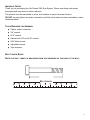
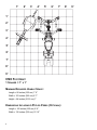
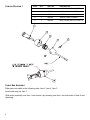
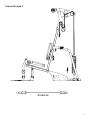
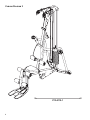
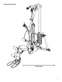
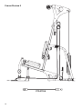
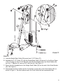
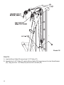
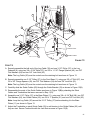
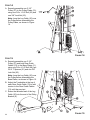
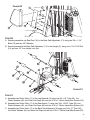
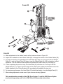
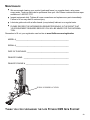
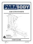
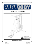
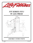
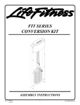
CM3 GYM SYSTEM
WARNING:
Read and follow all directions
for each step to ensure proper
assembly of this product.
USER’S GUIDE
CLASS H
PART # 7657801
REV. B
Version: CM3-108
Revision: 12/08/06
TABLE
OF
CONTENTS
Safety Statement . . . . . . . . . . . . . . . . . . . . . . . . . . . . . . . . . . . . . . . . . . . . . . . . . . . . . . . . . . .2
General Notes . . . . . . . . . . . . . . . . . . . . . . . . . . . . . . . . . . . . . . . . . . . . . . . . . . . . . . . . . . . . .3
Tools Required . . . . . . . . . . . . . . . . . . . . . . . . . . . . . . . . . . . . . . . . . . . . . . . . . . . . . . . . . . . . .3
Gym Layout . . . . . . . . . . . . . . . . . . . . . . . . . . . . . . . . . . . . . . . . . . . . . . . . . . . . . . . . . . . . . . .4
Parts List . . . . . . . . . . . . . . . . . . . . . . . . . . . . . . . . . . . . . . . . . . . . . . . . . . . . . . . . . . . . . . . . .5
Cabling Diagrams . . . . . . . . . . . . . . . . . . . . . . . . . . . . . . . . . . . . . . . . . . . . . . . . . . . . . . . . . . .6
Assembly Instructions . . . . . . . . . . . . . . . . . . . . . . . . . . . . . . . . . . . . . . . . . . . . . . . . . . . . . . .10
Maintenance . . . . . . . . . . . . . . . . . . . . . . . . . . . . . . . . . . . . . . . . . . . . . . . . . . . . . . . . . . . . . .29
Warranty . . . . . . . . . . . . . . . . . . . . . . . . . . . . . . . . . . . . . . . . . . . . . . . . . . . . . . . . . . . . . . . .30
Product Service . . . . . . . . . . . . . . . . . . . . . . . . . . . . . . . . . . . . . . . . . . . . . . . . . . . . . . . . . . .32
IMPORTANT SAFELY INFORMATION
THERE IS A RISK ASSUMED BY INDIVIDUALS
TO MINIMIZE RISK, FOLLOW THESE RULES!
WHO USE THIS TYPE OF EQUIPMENT.
1. Before using, read all the warnings and instructions on the use of this machine. Use only for
intended exercise. DO NOT modify the machine.
2. Obtain a medical exam before beginning any exercise program.
3. Keep body and clothing free of all moving objects.
4. Inspect the machine before use. DO NOT use it if it appears damaged. DO NOT attempt to fix a
broken or jammed machine. Notify your authorized Life Fitness dealer and have repairs made by
an authorized service technician before use.
5. Be certain that the weight pin is inserted completely. Use only the pin provided by the manufacturer. If unsure, call your authorized Life Fitness dealer.
6. Never pin the weights or prop plate into an elevated position. DO NOT use the machine if found
in this condition. DO NOT attempt to fix. Notify your authorized Life Fitness dealer.
7. Inspect cables and their connections before using machine. Pay particular attention to the cable
ends. DO NOT attempt to fix any problems. Notify your authorized Life Fitness dealer and have
repairs made by an authorized service technician before use.
8. Make sure all spring-loaded pull pins are fully engaged in the adjustment position and fully
tighten the thumbscrew before use.
9. Children must not be allowed near this machine. Supervise teenagers.
Note: In our continuing effort to improve our products, specifications are subject to change.
©2006 Life Fitness, a division of Brunswick Corporation. All rights reserved.
www.lifefitness.com
2
IMPORTANT NOTES
Thank you for purchasing the Life Fitness CM3 Gym System. Please read these instructions
thoroughly and keep them for future reference.
This product must be assembled on a flat, level surface to assure its proper function.
DO NOT securely tighten any frame connections until the entire frame has been assembled, unless
otherwise stated.
TOOLS REQUIRED
FOR
ASSEMBLY
O
Rubber mallet or hammer.
O
3/4" wrench.
O
9/16" wrench.
O
Ratchet with 3/4" and 9/16" sockets.
O
5/32" Allen wrench.
O
Adjustable wrench.
O
Tape measure.
BOLT LENGTH RULER
NOTE
THAT BOLT LENGTH IS MEASURED FROM THE UNDERSIDE OF THE HEAD OF THE BOLT.
BOLT LENGTH
0
1/2
1
1/2
2
1/2
3
1/2
4
1/2
5
1/2
6
3
1’
2’
3’
4’
5’
6’
7’
1’
2’
3’
4’
5’
6’
7’
8’
9’
CM3 FOOTPRINT
1 SQUARE = 1'
X
1'
MINIMUM REQUIRED USABLE SPACE:
Length = 90 inches (229 cm) 7' 6"
Width = 103 inches (262 cm) 8' 7"
Height = 84 inches (213.5 cm) 7'
DIMENSIONS INCLUDING LP5 LEG PRESS (OPTIONAL):
Length = 102 inches (259 cm) 8' 6"
Width = 130 inches (330 cm) 10' 10"
4
8’
9’
PARTS LIST
Note: Some of the components may be pre-assembled.
Key Part #
Description
Qty Key Part #
Description
Qty
1
ACU04-0906
FRONT BASE
1
38
ACU06-0035
4-1/2" PULLEY
3
2
ACU04-0909
ACU04-0909-107
UPRIGHT
1
39
ACUKN000097
QUICK CONNECT
4
3
ACU04-0907
BASE CONNECTOR
1
40
ACU11-0068
T-HANDLE SPRING PIN
1
4
ACU04-0908
REAR BASE
1
41
ACUDI1080080U
SNAP LINK
4
5
ACU04-0902
RIGHT ARM
1
42
ACU04-1343
GUIDE BRACKET
2
6
ACU04-0903
LEFT ARM
1
43
ACU06-0194
3-PRONG KNOB
1
7
ACU04-1162
SEAT ADJUST
1
44
ACU05-0277
ROLLER PAD CAP
6
8
ACU04-1157
LEG PEDESTAL
1
45
ACU06-0363
PLASTIC WASHER
12
10
ACU02-1071
PULLEY PLATE
2
46
ACU05-0146
1/2" RH WASHER
2
11
ACU02-1093
BASE PLATE
2
47
ACU06-0021
RH CAP
2
12
ACU05-0295
C-RING
2
48
ACU08-0074
3/8 X 3/4" FLANGE SPACER
2
13
ACU02-1092
BOOM PULLEY PLATE
2
49
ACU08-0066
3/8 X 1-1/16" FLANGE SPACER
2
14
ACU04-0905
RIGHT BOOM PLATE
1
50
ACU05-0300
ACCESSORY RING
2
15
ACU04-0904
LEFT BOOM PLATE
1
51
ACU03-0042
3/8" X 1" SPACER
9
16
ACU07-0100
SEAT/BACK PAD
2
52
ACUMD000059
WEIGHT STACK LABEL
1
17
ACU06-0337
ROLLER PAD
6
53
ACUDA1E03813416NB
3/8 X 1-3/4" BOLT
10
18
ACU01-2155
76" GUIDE ROD
2
54
ACUDAEE51610018YB
5/16 x 1" BUTTON HEAD
6
19
ACU12-0067
ADJUST. SEWN HANDLE
2
55
ACUDA1E03820016NB
3/8 X 2" BOLT
2
20
ACU12-0068
SHORT SEWN HANDLE
2
56
ACU06-0358
2" NYLON SPACER
4
21
ACU7292501
WEIGHT PLATE
15
57
ACUDA1E03833416NB
3/8 X 3-3/4" BOLT
18
22
ACU04-0622
LOW ROW BAR
1
58
ACUDA1C01210413NB
1/2 X 104mm BOLT
1
23
ACU10-0204ASY
HEAD PLATE ASSY
1
59
ACU05-0030
12 LINK CHAIN
1
24
ACU04-0932A
3/4 X 18" TUBE
1
60
ACUDA1E03823416NB
3/8 X 2-3/4" BOLT
2
25
ACU04-0934A
3/4 X 18-3/8" TUBE
1
61
ACUDA1C01253413NB
1/2 X 5-3/4" BOLT
1
26
ACU04-0935
3/4 X 21" TUBE
1
62
ACUDB2E01208000B
1/2" LOW HEIGHT LOCK NUT
2
27
ACU11-0060
WEIGHT STACK PIN
1
63
ACUDB2E03811000B
3/8" LOCK NUT
40
28
ACU06-0034
WEIGHT STACK CUSHION
2
64
ACUDC1250100020B
3/8" FLAT WASHER
18
29
ACU13-0112-2
WEIGHT STACK CABLE
1
65
ACU8D4AGG700-3
FRONT GUIDE CABLE
2
30
ACU13-0112-4
LEG CABLE
1
66
ACU04-1100
FOOT PLATE
1
31
ACU13-0112-5
ARM CABLE
1
67
ACUDA1E03830016NB
3/8 X 3" BOLT
4
32
ACU13-0112-1
BOOM CABLE
1
68
ACUDA1E03841416NB
3/8 X 4-1/4" BOLT
4
33
ACU04-1165
WEIGHT STACK SPACER
2
70
ACUDA1E03811416NB
3/8 X 1-1/4" BOLT
2
34
ACU04-1171
3-1/2" CABLE GUARD
1
71
AP04-0910
BACK PAD ADJUSTMENT
1
35
ACU04-1342
4-1/2" CABLE GUARD
1
72
P04-0911
SWIVEL PULLEY ASSEMBLY
2
36
ACU05-0212
SHAFT COLLAR
2
73
ACU12-0041
ANKLE STRAP
1
37
ACU06-0051
3-1/2" PULLEY
18
74
ACU13-0223-6
REAR GUIDE CABLE
2
ACU04-1213 CM3 Acc. Bar
Adapter (Black)
See paperclip
5
CABLING DIAGRAM 1
ITEM
QTY.
PART NO.
DESCRIPTION
1
1
7726201
COUPLER, QUICK CONNECT
2
1
7726401
HSNG, QUICK CONNECT
3
1
7726301
SLEEVE, QUICK CONNECT
4
1
3249901
SPRING, QUICK CONNECT
5
2
3250002
M5 X 0.8 HXS SOC CS ST BZ X 8
CABLE END ASSEMBLY:
Slide parts onto cable in the following order: Item 2, Item 4, Item 3.
Insert cable end into Item 1.
Slide entire assembly over Item 1 and secure it by screwing one Item 5 into both sides of Item 2 and
tightening.
6
CABLING DIAGRAM 2
P13-0112-2
7
CABLING DIAGRAM 3
P13-0112-1
8
CABLING DIAGRAM 4
P13-0112-5
9
CABLING DIAGRAM 5
P13-0112-4
10
FIGURE 1
2
3/8 X 2-3/4” 60
64
57
63
1
3
63
4
64
63
57 3/8 X 3-3/4”
11
66
63
67 3/8 X 3”
STEP 1:
A. Loosely assemble two Base Plates (11) to the Front Base (1) and the Base Connector (3) using
four 3/8 x 3-3/4" Bolts (57) and four 3/8" Lock Nuts (13). See Figure 1.
B. Loosely assemble the Footplate (66) to the Front Base (1) using one 3/8 x 3" Bolt (67) and one
3/8" Lock Nut (63) as shown in Figure 1.
C. Loosely assemble the Rear Base (4) to the Base Connector (3) using two 3/8 x 3-3/4" Bolts (57),
two 3/8" Washers (64) and two 3/8" Lock Nuts (63).
D. Loosely assemble the Upright (2) to the Front Base (1) using two 3/8 x 2-3/4" Bolts (60), two 3/8"
Washers (64) and two 3/8" Lock Nuts (63).
11
5
6
63
64
2
68 3/8 X 4-1/4”
63
4
64
57 3/8 X 3-3/4”
FIGURE 2
STEP 2:
A. Loosely assemble the Right Arm (5) and Rear Base (4) using two 3/8 x 3-3/4" Bolts (57), two 3/8"
Washers (64) and two 3/8" Lock Nuts (63).
B. Loosely assemble the Left Arm (66) and Rear Base (4) using two 3/8 x 3-3/4" Bolts (57), two 3/8"
Washers (64) and two 3/8" Lock Nuts (63).
C. Loosely assemble both the Left Arm (5) and the Right Arm (6) to the Upright (2) using two 3/8 x
4-1/4" Bolts (57), four 3/8" Washers (64) and two 3/8" Lock Nuts (63).
0
12
1/2
1
1/2
2
1/2
3
1/2
4
1/2
5
1/2
6
FIGURE 3
Make sure that the Weight Plates (21) are assembled as shown in Figure 3 and the Head Plate
Assembly (23) is assembled as shown in Figure 4.
FIGURE 4
13
36
18
23
21
28
33
CM3 SHROUD
OPTION ONLY!
4
FIGURE 5
STEP 5:
A. Insert two Guide Rods (18) into the Rear Base (4) as shown in Figure 5. (Note: If you purchased
the CM3 Shroud Option, place the Guide Rods (18) through the Bottom Shroud Bracket (found in
Shroud Option box) and into the Rear Base (4) as shown in Figure 5.)
B. Lubricate Guide Rods (18) with silicon lube included with gym, or a silicon or teflon lube spray.
C. Slide two Weight Stack Spacers (33) and two Weight Stack Cushions (28) over Guide Rods (18).
D. Using extreme care, slide all fifteen Weight Plates (21) over the Guide Rods (18) and down onto
the Weight Stack Cushions (28). Make sure the Weight Plates (21) all face as shown.
E. Slide the Head Plate Assembly (23) down the Guide Rods (18), onto the weight plate stack.
F. Slide two Shaft Collars (36) over the Guide Rods (18) as shown in Figure 5.
14
FIGURE 6
STEP 6:
A. Swing the Guide Rods (18) into the guide rod bushings in the Right Boom Plate (14) and Left
Boom Plate (15) as shown in Figure 6.
B. Loosely assemble the Right Boom Plate (14) and Left Boom Plate (15) to the Upright (2) using
three 3/8 x 3-3/4" Bolts (57) and three 3/8" Lock Nuts (63). See Figure 6.
C. Securely tighten all the nuts and bolts on the gym, starting with the nuts and bolts on the
frame, before proceeding any further.
D. Slide the Shaft Collars (36) to the top of the Guide Rods (18) and tighten set screws as shown in
Figure 6.
16
7
64
3/8 X 3” 67
FIGURE 7
STEP 7:
A. Securely assemble one Seat/Back Pad (16) to the Seat Adjust (7) using two 3/8 x 3" Bolts (67)
and two 3/8" Washers (64). See Figure 7.
15
1/2 X 104mm 58
3
46
43
8
1
62
47
SPRING PIN
FIGURE 8
STEP 8:
A. Securely assemble the Three Prong Knob (43) to the Front Base (1) as shown.
B. Insert the Seat Adjust Assembly (7) into the Front Base (1) as shown. The seat height can be
adjusted using the Spring Pin and can be secured with the Three Prong Knob (43).
C. Assemble the Leg Pedestal (8) to the Front Base (1) using two RH caps (47), one 1/2 x 104mm
Bolt (58), two 1/2" Washers (46) and one 1/2" Low Height Lock Nut (62).
Note: Tighten this connection enough to prevent excess play yet allow the Leg Pedestal to
rotate freely.
16
FIGURE 9
STEP 9:
A. Detach Short Cable from both Rear Guide Cables (74) as shown in Figure 9 (B).
B. Slide Long Cables of Rear Guide Cables (74) through eyelets of Guide Bracket (42) as shown in
Figure 9 (B). Reattach Short Cable of Rear Guide Cables (74) to Long Cable, leaving Guide
Bracket (42) loose.
D. Assemble two Boom Pulley Plates (13) and two 3-1/2" Pulleys (37) to the Boom Plates (14 & 15)
using two 3/8 x 3-3/4" Bolts (57) and two 3/8" Lock Nuts (63). See Figure 9.
E. Loosely assemble one 4-1/2" Pulley (38), one 4-1/2" Cable Guard (35) and one 1" Spacer (51) to
the Boom Plates (14 & 15), using one 3/8 x 3-3/4" Bolt (57) and one 3/8" Lock Nut (63).
F. Loosely assemble one 3-1/2" Pulley (37), one 3-1/2" Cable Guard (34), one 1" Spacer (51) and
both Rear Guide Cables (74) to the Boom Plates (14 & 15), using one 3/8 x 4-1/4" Bolt (68) and
one 3/8" Lock Nut (63).
NOTE: Guide Bracket (42) will remain loose until attached to pulley assembly in later step.
17
IMPORTANT!
UNCOIL AND
INSTALLING.
STRAIGHTEN ALL CABLES TO REMOVE ALL TWISTS BEFORE
STEP 10:
A. Assemble the Weight Stack Pin (27) to the
Head Plate Assembly (23) as shown in
Figure 10.
B. Screw the long threaded end of the Weight
Stack Cable (29) into the end of the Head
Plate Assembly (23). See Figure 10.
C. Route the Weight Stack Cable (29) around
the pulleys in the Boom Plates (14 & 15) as
shown in Figure 10.
Note: Make sure the cable runs in the
grooves of the pulleys.
D. Tighten the two 3/8 x 3-3/4" Bolts (57) holding the 3-1/2" Cable Guard (34) and the 41/2" Cable Guard (35)
Note: Make sure the guards are oriented
correctly.
E. Assemble two Pulley Plates (10) around
one 3-1/2" Pulley (37), using one 3/8 x
1-3/4" Bolt (53) and one 3/8" Lock Nut (63)
as shown in Figure 10.
FIGURE 10
18
FIGURE 11
STEP 11:
A. Loop the Weight Stack Cable (29) around one 3-1/2" Pulley (37).
B. Assemble the 3-1/2" Pulley (37) with the Weight Stack Cable (29) around it to the Boom Plates
(14 & 15) using one 3/8 x 4-1/4" Bolt (68), two 3/8" Flat Washers (64), two Guide Cables (65),
two 3/8 x 1" Spacers (51) and one 3/8" Lock Nut (63). See Figure 11.
C. Screw the short threaded end of the Weight Stack Cable (29) into the end of the Guide Bracket
(42). See Figure 11.
D. Disassemble the Short Cables and the Turnbuckles on the ends of the Guide Cables (65) as
shown in Figure 11. Set these pieces aside; the Guide Cables will be reassembled later.
19
FIGURE 12
STEP 12:
A. Loop the Boom Cable (32) around one 3-1/2" Pulley (37).
B. Assemble the 3-1/2" Pulley (37) with the Boom Cable (32) looped around it to the Guide Bracket
(42), using one 3/8 x 1-3/4" Bolt (53) and one 3/8" Lock Nut (63).
20
63
51
64
8
2
63
48
37
49
3/8 X 4-1/4” 68
11
30
42
67 3/8 X 3”
TURN BUCKLE
64
65 SHORT CABLE
3/8 X 3-3/4” 57
(B)
FIGURE 13
STEP 13:
A. Securely assemble the ball end of the Leg Cable (30) and one 3-1/2" Pulley (37) to the Leg
Pedestal (8), using two 3/8 x 3-3/4" Bolts (57), two 3/8 x 1-1/16" Flange Spacers (49), two 3/8"
Flat Washers (64) and two 3/8" Lock Nuts (63).
Note: The Leg Cable (30) must be routed over the retaining bolt as shown in Figure 13.
B. Securely assemble one 3-1/2" Pulley (37) to the Front Base (1), using one 3/8 x 3" Bolt (67), two
3/8 x 3/4" Flange Spacers (49), two 3/8" Flat Washers (64) and one 3/8" Lock Nut (63).
Note: The Leg Cable (30) must be routed over the retaining bolt as shown in Figure 13.
C. Carefully slide the Guide Cables (65) through the Guide Bracket (43) as shown in Figure 13(B).
D. Reassemble the ends of the Guide Cables as shown in Figure 13(B)by attaching the Short
Cables and Turnbuckles that were removed in Step 11(D).
E. Assemble one 3-1/2" Pulley (37) to the Base Plates (11), using one 3/8 x 4-1/4" Bolt (68), two 3/8"
Flat Washers (64), two Guide Cables (65), two 3/8 x 1" Spacers (51) and one 3/8" Lock Nut (63).
Note: Loop the Leg Cable (30) around the 3-1/2" Pulley (37) before attaching it to the Base
Plates (11), as shown in Figure 13.
F. Adjust the Turnbuckle on each Guide Cable (65) to add tension to the Guide Cables (65) until
they are taut. Secure Turnbuckle with the Jam Nuts as seen in Figure 13(B).
21
STEP 14:
A. Securely assemble one 3-1/2"
Pulley (37) to the Pulley Plates (10),
using one 3/8 x 1-3/4" Bolt (53) and
one 3/8" Lock Nut (63).
Note: Loop the Leg Cable (30) over
the Pulley before assembling the
Pulley Plates, as shown in Figure
14.
FIGURE 14
STEP 15:
A. Securely assemble one 3-1/2"
Pulley (37) and both Rear Guide
Cables (74) to the Base Plates (11),
using one 3/8 x 4-1/4" Bolt (68), two
3/8 x 1" Spacers (51) and one 3/8"
Lock Nut (63).
Note: Loop the Leg Cable (30) over
the Pulley before assembling the
Base Plates, as shown in Figure 15.
B. Adjust the Turnbuckle at the top of
each Rear Guide Cable (74) to add
tension to the Rear Guide Cables
(74) until they are taut.
C. Screw the threaded end of the Leg
Cable (30) into the end of the Pulley
Bracket (9).
22
FIGURE 15
FIGURE 16
STEP 16:
A. Route the Arm Cable (31) through the Left Arm (6) as shown in Figure 16.
B. Loop the Arm Cable (31) around one 4-1/2" Pulley (38).
C. Securely assemble the 4-1/2" Pulley (38) with the Arm Cable (31) around it to the Left Arm (6),
using one 3/8 x 2" Bolt (55) and one 3/8" Lock Nut (63).
23
FIGURE 17
STEP 17:
A. Securely assemble two 3-1/2" Pulleys (37) to the Base Plates (11), using two 3/8 x 3-3/4" Bolts
(57), one 3/8 x 1" Spacer (51) and two 3/8" Lock Nuts (63).
B. Loop the Arm Cable (31) between the two Pulleys (37) around one 3-1/2" Pulley (37) as shown
in Figure 17.
C. Securely assemble the 3-1/2" Pulley (37) with the Arm Cable (31) around it to the Guide Bracket
(42), using one 3/8 x 1-3/4" Bolt (55) and one 3/8" Lock Nut (63).
24
FIGURE 18
STEP 18:
A. Route the Arm Cable (31) through the Right Arm (5) as shown in Figure 18.
B. Loop the Arm Cable (31) around one 4-1/2" Pulley (38).
C. Securely assemble the 4-1/2" Pulley (38) with the Arm Cable (31) around it to the Right Arm (6),
using one 3/8 x 2" Bolt (55) and one 3/8" Lock Nut (63).
25
FIGURE 19
STEP 19:
A. Insert Arm Cable (31) ends through Swivel Pulley Assemblies (72).
B. Insert Swivel Pulley Assemblies (72) into Left Arm (5) and Right Arm (6).
C. Secure Swivel Pulley Assemblies (72) in Left Arm (5) and Right Arm (6) using one C-Ring (12)
each.
C. Attach Quick Connects (39) to each end of the Arm Cable (31). See Diagram 1, page 6.
26
FIGURE 20
71
3/8 X 1-1/4” 70
64
2
62
16
1/2 X 5-3/4” 61
STEP 20:
A. Securely assemble one Seat Pad (16) to the Back Pad Adjustment (71) using two 3/8 x 1-1/4"
Bolts (70) and two 3/8" Washers.
B. Securely assemble the Back Pad Adjustment (71) to the Upright (2), using one 1/2 x 5-3/4" Bolt
(61) and one 1/2" Low Height Lock Nut.
FIGURE 21
STEP 21:
A. Assemble two Roller Pads (17) to the Leg Pedestal (8) using one 3/4 x 18" Tube (24), four
Plastic Washers (45), two Roller Pad Caps (44) and two 5/16 x 1" Button Head Allen Screws (54).
B. Assemble two Roller Pads (17) to the Seat Adjust (7) using one 3/4 x 18-3/8" Tube (25), four
Plastic Washers (45), two Roller Pad Caps (44) and two 5/16 x 1" Button Head Allen Screws (54).
C. Assemble two Roller Pads (17) to the Back Pad Adjustment (8) using one 3/4 x 21" Tube (26),
four Plastic Washers (45), two Roller Pad Caps (44) and two 5/16 x 1" Button Head Allen Screws (54).
27
FIGURE 22
STEP 22:
A. Make adjustments to the cables’ tension at the locations shown in Figure 22.
B. Adjust the Turnbuckle on each Guard Cable (65) to change the tension of the Guide Cables (65).
C. If by the time the Gym is assembled, the Head Plate (23) does not sit on top of the first Weight
Plate (21), push the Head Plate (23) down, insert the Weight Stack Pin (27) and perform several
repetitions. This will relax the cable system and prevent the Head Plate (23) from lifting up.
D. If after completing the previous step, the Head Plate (23) still does not sit on top of the first
Weight Plate (21) or if there is excess slack in the cable system, adjust the threaded ends of the
Cables attached to the Pulley Brackets (42) accordingly and retighten the jam nuts.
E. For maximum performance, the Head Plate (23) should just barely sit on the Weight Plate (21).
F. After making adjustments, make sure all jam nuts are securely tightened.
This completes the assembly of the CM3 Gym System. To add the CM3 Shroud Option
(purchased seperately), refer to the CM3 Shroud Kit Assembly Instructions.
28
MAINTENANCE
O
We recommend cleaning your product (pads and frame) on a regular basis, using warm
soapy water. Touch-up paint can be purchased from your Life Fitness customer service representative at 1-800-351-3737.
O
Inspect equipment daily. Tighten all loose connections and replace worn parts immediately.
Failure to do so may result in serious injury.
O
Lubricate guide rods with a teflon based (or equivalent) lubricant on a regular basis.
O
PLEASE RECORD THE INFORMATION REQUESTED BELOW. IN THE EVENT THAT
YOUR EQUIPMENT REQUIRES SERVICE YOU WILL BE ASKED FOR THIS INFORMATION. .
Remember to fill out your registration card on-line at www.lifefitness.com/registration
.
MODEL #______________________________________________________
SERIAL #______________________________________________________
DATE OF PURCHASE: ___________________________________________
DEALER’S NAME: ______________________________________________
DEALER’S PHONE # ____________________________________________
SERIALNUMBER LOCATION
THANK YOU
FOR PURCHASING THE
LIFE FITNESS CM3 GYM SYSTEM!
29
WARRANTY
Life Fitness extends the following LIMITED WARRANTY to the original owner of the Life Fitness products. The Warranty
terms apply to IN HOME USE ONLY.
1. LIMITED WARRANTY ON FRAME AND WELDS. If the frame of the Life Fitness product or a weld should crack or
break, it will be repaired or replaced by Life Fitness. Terms: Lifetime – for so long as the Customer owns the Life
Fitness product.
2. LIMITED WARRANTY ON PARTS. If the following parts are defective in material or workmanship, Life Fitness will
supply replacement parts: all bolts, nuts, washers, bearings, bushings, pulleys, thumbscrews, collars, cable retaining
clips, adjustable pre-stretch slides, roller pad shafts, allen head bolts, weight selector pin, weight stack shaft, set
screws, protector caps, adjustment chain, cotter pin, plunger, spring and knob. Terms: Lifetime – for so long as the
Customer owns the Life Fitness product.
3. LIMITED WARRANTY ON CABLES AND UPHOLSTERY. If the coated cables or upholstery are defective in material
or workmanship, Life Fitness will repair or replace them, at its option. Terms: Three (3) years.
4. CONDITIONS AND EXCEPTIONS. Any product misuse, abuse or alteration, any attempt to repair by a person other
than an authorized Life Fitness Service Center, any improper assembly, accident, or any other condition resulting
from occurrences beyond the control of Life Fitness will void this Limited Warranty.
5. REPLACEMENT AND REPAIR EXPENSES. Life Fitness will provide only replacement parts or repair under this warranty. The Owner is responsible for all other costs. Such costs may include, but are not limited to: a. labor charges
for service, removal, repair or reinstallation of the Life Fitness product or any component part; b. shipping, delivery,
handling and administrative charges for returning parts to Life Fitness; and c. all necessary or incidental costs related to installation of the replacement parts.
6. SHIPPING. If shipping by the Owners is deemed necessary (in sole discretion of Life Fitness), parts should be
shipped in their original carton or equivalent packaging, fully insured with shipping charges prepaid. Life Fitness will
not assume any responsibility for any loss or damage incurred in shipping.
7. CLAIM PROCEDURES. If service on your Life Fitness product is required during the warranty period, please contact
our Customer Service Department at 1-800-351-3737 for instructions regarding returning or replacing parts. Please
have available the following information: (i) the dealer’s name; (ii) the date of purchase; (iii) the serial # (s) of your
product (the serial number location is called out on the final assembly drawing included with your assembly instruction); (iv) a description of the nature of the problem.
8. OWNER’S RIGHT. This Limited Warranty gives you specific legal rights. You may also have other rights, which vary
depending on local law.
9. LIMITATION OF IMPLIED WARRANTIES. All implied warranties, except to the extent prohibited by applicable law,
shall have no greater duration than the warranty period set forth above. There are no warranties which extend
beyond the description in this Limited Warranty.
Because local laws do not allow limitations on how long an implied warranty lasts, the above limitations may not
apply to you.
10. DISCLAIMER. No other express warranty has been made or will be made on behalf of Life Fitness with respect to
any Life Fitness product or the operation, repair or replacement of any Life Fitness product. Life Fitness shall not be
responsible for injury, loss of use of the Life Fitness product, inconvenience, loss or damage to personal property,
whether direct or indirect, and incidental or consequential damages. The above limitation or exclusion may not apply
to you.
30
CORPORATE HEADQUARTERS
5100 North River Road
Schiller Park, Illinois 60176 • U.S.A.
847.288.3300 • FAX: 847.288.3702
800.351.3737 (Toll-free within U.S.A., Canada)
www.lifefitness.com
INTERNATIONAL OFFICES
LIFE FITNESS ASIA PACIFIC LTD
Room 2610, Miramar Tower
132 Nathan Road
Tsimshatsui, Kowloon
HONG KONG
Telephone: (+852) 2891.6677
FAX: (+852) 2575.6001
LIFE FITNESS ATLANTIC BV
LIFE FITNESS BENELUX
Bijdorpplein 25-31
2992 LB Barendrecht
THE NETHERLANDS
Telephone: (+31) 180.646.666
FAX: (+31) 180.646.699
LIFE FITNESS BENELUX NV
Parc Industriel de Petit-Rechain
4800 Verviers
BELGIUM
Telephone: (+32) 87.300.942
FAX: (+32) 87.300.943
LIFE FITNESS DO BRAZIL
Av. Dr. Dib Sauaia Neto 1478
Alphaville, Barueri, SP
06465-140
BRAZIL
Telephone (+55) 11.4193.8282
FAX: (+55) 11.4193.8283
LIFE FITNESS AUSTRIA
Vertriebs GmbH
Hintschiggasse 1
1100 Vienna
AUSTRIA
Telephone: (+43) 1.61 57 198
FAX: (+43) 1.61 57 198.20
LIFE FITNESS IBERIA
Pol. Ind. Molí dels Frares. c/C, nº 12
08620 Sant Vicenç dels Horts (Barcelona)
España
Telephone: (+34) 93.672.4660
FAX: (+34) 93.672.4670
LIFE FITNESS EUROPE GMBH
Siemensstrasse 3
85716 Unterschleissheim
GERMANY
Telephone: (+49) 89.31 77 51.0
FAX: (+49) 89.31 77 51.99
LIFE FITNESS ITALIA S.R.L.
Via San Pieretto
37010 AFFI (Verona)
ITALY
Telephone: (+39) 045.7238204
FAX: (+39) 045.7238197
LIFE FITNESS LATIN AMERICA
AND CARIBBEAN
5100 North River Road
Schiller Park, Illinois 60176
U.S.A.
Telephone: (+1) 847.288.3300
FAX:(+1) 847.288.3762
LIFE FITNESS UK LTD
Queen Adelaide
Ely, Cambs CB7 4UB
UNITED KINGDOM
Telephone: (+44) 1.353.666 017
FAX: (+44) 1.353.666 018
LIFE FITNESS JAPAN
Nippon Brunswick Bldg., #8F
5-27-7 Sendagaya
Shibuya-Ku, Tokyo
Japan 151-0051
Telephone: (+81) 3.3359.4309
FAX: (+81) 3.3359.4307
31