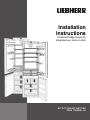
1
Installation
Instructions
Combined fridge-freezer for
integrated use, door-on-door
HC 1011/1060 HC 1001/1050
20/08 7084000 - 00
General safety information
2 Setting up the appliance
Contents
1
General safety information...........................
2
2
Setting up the appliance...............................
2
3
3.1
3.2
3.3
Changing the door hinges............................
To detach the soft stop mechanism..................
Reversing the door...........................................
Re-attaching the soft stop mechanism.............
3
3
3
3
4
4.1
4.2
4.3
Kitchen Cabinet Construction......................
Kitchen Cabinet Airflow....................................
Designing the Kitchen Cabinet.........................
Designing the Kitchen Cabinet Doors...............
4
4
5
6
5
Water supply..................................................
8
6
6.1
6.2
Installation...................................................... 8
Assembling the appliance................................ 9
Fitting the unit doors......................................... 11
7
Connecting the appliance............................. 12
The manufacturer is constantly working to improve all models. Therefore please understand that we reserve the right
to make design, equipment and technical modifications.
To get to know all the benefits of your new appliance, please
read the information contained in these instructions carefully.
The instructions apply to several models, so there may be
differences. Sections which only apply to certain appliances
are indicated with an asterisk (*).
Instructions for action are marked with a , the results
of action are marked with a .
1 General safety information
Read and follow these instructions. They contain safety advice which is important for safe and problem-free installation and operation. Always read and follow the safety advice.
DANGER
indicates a hazardous situation,
which if not avoided, will result in
death or serious injury.
WARNING
indicates a hazardous situation,
which if not avoided, could result in
death or serious injury.
CAUTION
indicates a hazardous situation,
which if not avoided, will result in minor or moderate injury.
NOTICE
indicates a hazardous situation,
which if not avoided, could result in
damage to property.
Note
indicates useful advice and tips.
It is important that the guidelines and instructions in this
manual are followed so that the appliance is correctly installed and operates properly. Read and understand all information in this manual before the appliance is installed.
2
WARNING
Risk of fire due to moisture!
If live parts or the power cord get wet, this can cause a short
circuit.
u The appliance is designed for use in enclosed spaces.
Do not operate the appliance in open space or in damp
areas or where there is spray.
WARNING
Danger of fire and damage!
u Do not place devices that give off heat, e.g. microwaves,
toasters, etc. on the appliance.
CAUTION
Risk of personal injury!
u Have two people move this appliance into place.
NOTICE
Risk of damage caused by condensation
Installing the appliance next to any other refrigerator or
freezer can cause damage or condensation to the Liebherr
appliance.
u Do not install this appliance next to any other refrigerator
or freezer except another Liebherr model. Liebherr models are designed to allow side-by-side installation. They
are equipped with a heating system to eliminate condensation when refrigerators or freezers are installed sideby-side.
NOTICE
Risk of damage for the finished floor surface!
u Protect the finished floor surface before you uncrate the
unit.
Verify that:
q the floor under the appliance is flat and level.
q the floor can support the appliance's weight plus approximately 1200 pounds (544 kg) of food weight.
q the appliance is not placed in direct sunlight or near the
stove, range top, radiators and similar heat sources.
q the kitchen cabinet that the appliance is installed in is
shimmed to the floor level if the floor heights are not
equal.
q cutout dimensions are accurate.
q electrical outlet is in correct location.
q the air flow is not restricted. Air flow must be provided for
the appliance to operate properly. The factory air vents
provide 31 square inches (200 cm2) of air flow per appliance. If you are replacing the air vents with an overlay,
the air flow must be the same or greater than the factory
air vents.
Changing the door hinges
u Examine the unit and packaging for shipping damage.
Contact the carrier immediately if you suspect there is
any damage.
u Note the type (model, number), index, appliance/serial
number, date of purchase and where purchased on the
spaces provided in see Appliance Information.
u Remove anything attached to the rear or side walls of
appliance that would prevent proper installation or impede proper ventilation.
If the appliance is set up in humid areas, condensation may
build on the outside of the appliance.
u Always ensure proper ventilation.
3.2 Reversing the door
3 Changing the door hinges
Make sure you have the following tools on hand:
q Hex wrench 13
q Cordless screwdriver Torx 15, 20, 25, 30
Push the appliance 2/3 of the way into the recess.
Disconnect the power plug.
Open the doors.
3.1 To detach the soft stop mechanism*
CAUTION
Risk of injury if soft stop contracts!
u Detach with care.
Fig. 2
u Lift off covers Fig. 2 (5,6,7,8) using a slot screwdriver.
u Just loosen top and bottom screws Fig. 2 (9) on the body
of the appliance.
u Push doors outwards and unhook.
u Swap screws Fig. 2 (9) to the opposite side and screw
them in a little.
CAUTION
Risk of injury if hinges fold!
u Leave hinges open.
Fig. 1
u Unscrew retainer Fig. 1 (1).
u Unscrew ball stud Fig. 1 (3) together with the soft stop
mechanism Fig. 1 (2) from the door and set to one side.
u Undo screws Fig. 2 (10) and change over the hinges diagonally.
The screws Fig. 2 (10) are self-tapping: use a cordless
screwdriver.
u Tighten the hinges.
u Close off the now unused fastening holes with the
plugs Fig. 2 (11) supplied.
u Hang doors on the pre-fitted screws Fig. 2 (9) and tighten
screws.
3.3 Re-attaching the soft stop mechanism*
u Screw on retainer Fig. 3 (1).
Fig. 3
3
Kitchen Cabinet Construction
u Screw in ball stud Fig. 3 (3) together with the soft stop
mechanism Fig. 3 (2) in the fastening hole.
u Re-attach all covers Fig. 2 (5,6,7,8).
- The top ventilation space can be either directly over the
appliance Fig. 4 (2) or next to the ceiling over a cabinet
Fig. 4 (3), or through a vent installed in a soffit Fig. 4 (4).
4 Kitchen Cabinet Construction
This is a fully integrated appliance which means that it is
fully enclosed by a kitchen cabinet. This type of cabinet
must be carefully constructed using the proper dimensions
and it must provide proper ventilation to ensure proper appliance operation.
Make a separate kitchen cabinet
for each appliance for Side-bySide installations.
Consider having a professional install the appliance in your
kitchen cabinet.
4.1 Kitchen Cabinet Airflow
Fig. 5
- There must be a clear ventilation space (without any obstructions) of at least 1-1/2 in. (38 mm) at the back of the
kitchen cabinet.
u Observe the above ventilation dimensions.
Ventilation through the cabinet base at the bottom can be
achieved by installing the provided ventilation grille Fig. 6 (3)
or via a ventilation opening of at least 31 in2 (200 cm2). When
using the provided ventilation grille Fig. 6 (3), please proceed
as follows:
Fig. 4
- There must be a ventilation space at least 31 in 2
(200 cm2) at the airflow inlet Fig. 4 (1) and at the airflow
outlet Fig. 4 (2).
4
Kitchen Cabinet Construction
u Insert ventilation grille Fig. 6 (3) into the cabinet base cutout Fig. 6 (1).
u From the back side, slide the snap-fits Fig. 6 (2) into the
grille until the hooks make contact with the cabinet base.
u Completely mount cabinet base (with ventilation grille
and snap-fits) to kitchen cabinet.
4.2 Designing the Kitchen Cabinet
Install the appliance in stable kitchen cabinets only.
Fig. 6
u In the cabinet base, cut out a ventilation opening that is
17-23/32 in. (450 mm) in width and 2-7/32 in. (56 mm) in
height.
Fig. 6
1
2
Power cord
Level
3
4
Electrical outlet
Fish line for power cord
A
21-7/32 in. (539 mm)
B
69-21/32 in. (1769.5 mm)
C
21-15/16 in. (557 mm)
D
69-3/4 in. - 70-3/8 in. (1772 mm) - (1788 mm)
E
24 in. (609.6 mm) (American Style Cabinet)
F
21-21/32 in. (550 mm)
23-5/8 in. (600 mm) (European Style Cabinet)
G
1-1/2 in. (38 mm)
H
27-3/8 in. (695 mm)
J
24-3/4 in. (629 mm)
K
max. 3/4 in. (19 mm)
L
9-21/32 in. (245 mm)
u Construct the kitchen cabinet using the dimensions
shown in Fig. 6.
u Align the kitchen cabinet with a level Fig. 6 (2) and a
square. If necessary, shim underneath the cabinet to
make it level.
5
Kitchen Cabinet Construction
w The floor and side walls must be at right angles to each
other.
The joint between the upper and the lower kitchen cabinet
door must align with the joint between the upper and lower
appliance door.
Follow distance L to the wall to allow the drawers to be
pulled out properly.
u Follow the dimensions provided in Fig. 6.
4.3 Designing the Kitchen Cabinet
Doors
Fig. 7
6
You need two doors for the kitchen cabinet, one on top for
the refrigerator compartment, and one on the bottom for the
freezer compartment.
In general, the doors have these characteristics:
- The doors should be at least 5/8 in. (16 mm) and max.
3/4 in. (19 mm) thick to allow the connecting rails to be
fastened to them.
- With both doors closed, there should be a minimum of
1/8 in. (3 mm) between the upper and lower doors.
- Also, there should be an 1/8 in. (3 mm) clearance between the upper door and the cabinet door above it (if
any).
- The top edge of the upper door Fig. 7 (1) and lower door
Fig. 7 (2) should be even with the doors of adjoining cabinet(s), if any.
- The position of the joint between the kitchen cabinet
doors must be level with the position of the joint Fig. 7 (2)
between the appliance doors.
- Adjust the door alignment before installing the appliance.
It is impossible to adjust the door with the appliance installed.
u Check the installation dimensions according to Fig. 6.
Kitchen Cabinet Construction
Fig. 7
1
2
Unit door fridge compartement
3 Fridge compartement door
Unit door freezer comparte4 Freezer compartement door
ment
The freezer door height is 24-24/32 in. (629 mm).
Of course, the final door height depends on the gap position
u To cover the lower part of the appliance: increase the of the cabinets that stand to the left and right of the appliheight of the panel to 27-3/32 in. (695 mm).
ance cabinet.
The thickness of the floor board is usually 3/4 in. (19 mm). If there is other furniture standing close to the appliance
u To cover the face side of the floor boardFig. 7 (a): increase cabinet this furniture typically has a gap between two drawthe height of the panel to 27-3/8 in. + 3/4 in. = 28-1/8 in. ers or two doors. Depending on your kitchen, these gaps
( 695 mm + 19 mm = 714 mm ).
are approximately 1/8 in. (3 mm) wide.
Without door panels on the unit, there is a gap of 19/32 in. u In this case, increase the height of the panel to 27-3/8 in.
+ 3/4 in. + 19/32 in. - 1/8 in. = 28-19/32 in. ( 695 mm +
(15 mm) betwenn the freezer Fig. 7 (4) and the refrigerator
19 mm + 15 mm - 3 mm = 726 mm ).
door Fig. 7 (3). After the installation of the cabinet doors, the
gap between the two doors Fig. 7 (1,2) will only be around The height of the refrigerator door panel is:
1/8 in. (3 mm) and must be in the hatched area.
7
Water supply
u The total opening of the cabinet (i.e. 70-3/8 in.
(1788 mm)) plus the thickness of the top as well as the
floor board (usually 3/4 in. (19 mm)) minus the height of
the freezer door panel (xxx in. (xxx mm)) as calculated
above and subtract the width of the gap (approximately
1/8 in. (3 mm)): 70-3/8 in. + 3/4 in. + 3/4 in. - xxx in. - 1/8 in.
= 71-25/32 in. - xxx in. ( 1788 mm + 19 mm + 19 mm xxx mm - 3 mm = 1823 mm – xxx mm )
5 Water supply*
WARNING
Electrical Shock Hazard!
u Do not make the water connection while the appliance is
connected to an electrical outlet.
u Disconnect the water supply before connecting the water
lines for the IceMaker.
u The connection to the water supply may only be made by
a trained and licensed plumber.
- Do not damage or bend the water supply pipe during installation.
u Connect the straight portion of the supplied stainless
steel hose to the solenoid valve.
The solenoid valve is located on the back of the appliance
at the bottom. The connecting dimension on the solenoid
valve is ¾”.
u Connect the bent portion of the stainless steel hose to
the shut-off valve.
u Open the shut-off valve of the water supply
pipe and check the entire water system to ensure there are no leaks.
Before initial operation:
u Have a competent fitter bleed the water supply
pipe.
6 Installation
All installation components are supplied with the appliance.
WARNING
Poisoning Hazard!
u The water quality must comply with the drinking water
regulations for the geographical area where the appliance is located.
u The IceMaker is designed exclusively to make ice cubes
in quantities needed by a household and must only be
operated with water appropriate for this purpose.
- The water pressure must be between 21.76 psi (1.5 bar) and
87.02 psi (6 bar). (0,15 MPa 0,6 MPa)
- Water must be supplied to the
appliance by means of a coldwater pipe that can withstand
the operating pressure and
conforms to hygiene regulations.
Use the supplied steel hose
(59-1/16 '' (1.5 m) ) to connect
to the water supply. A
118-1/8 '' (3 m) hose is available from Customer Service.
This hose must be installed by
a qualified fitter.
The connecting piece of the
hose contains a filter with a gasket seal.
- A shut-off valve must be provided between the hose line and
the domestic water supply to
turn off the water supply, if necessary.
- All devices and fixtures used to
supply water must comply with
the regulations in force in the
respective country.
8
Fig. 8
Make sure you have the following tools on hand:
q Cordless Torx 15. 20. 25 screwdrivers
q Hexagonal wrench 13
The floor and side walls of the unit must be at right angles
to one another. Level the unit using a spirit level and set
square. If necessary, level up by placing something underneath.
The appliance can also be built into a normal kitchen cabinet. In this case, detach the fittings on the unit door and the
recess. They are no longer needed, as the unit door is fitted
to the appliance door.
Installation
Note
u Before assembling the unit door, make sure that the permitted weight for the unit doors is not exceeded.
u Otherwise damage to the hinges and malfunctions arising from this cannot be ruled out.
6.1 Assembling the appliance
Maximum weight of unit door
Fridge compartment door
30.5 lbs (14 kg)
Freezer compartment door
26.5 lbs (12 kg)
Fig. 9
u Remove the power supply cable from the back of the
appliance. Also remove the cable holder, otherwise
there will be vibration noise!
u Position the power supply cable
using a piece of string so that
the appliance can easily be
connected to the electricity supply after it has been installed.
Fig. 10
For appliances with a fixed water supply for the IceMaker:
9
Installation
u Connect the IceMaker as indicated the section entitled
Water Supply.*
u Push the appliance 3/4 of the way into the recess.
u Remove the covers (5,6,7).
u Screw Fig. 11 (61) the equalizer trim Fig. 11 (20)to the appliance through the oblong
holes on top.
u Fasten all mounting
brackets Fig. 12 (34) with
hex
head
screws
Fig. 12 (35) to the prebored holes in the appliance door.
With 5/8 '' (16 mm) thick unit
walls = 22-3/8 '' (568 mm) wide
recess:
u Clip a spacer Fig. 13 (23) onto
the upper hinges and a spacer
Fig. 9 (24) onto the lower hinges.
u Attach the top and bottom
covers Fig. 14 (53) to the
mounting
brackets
Fig. 14 (50).
u Fasten
the
mounting
brackets Fig. 14 (50) at the
top with screws Fig. 14 (55)
and at the bottom with
screws Fig. 9 (51) such that
the bracket can still be
moved slightly to the left
and to the right.
u Remove the protective film from the trim
Fig. 15 (22).Attach the trim Fig. 15 (22) on
the handle side and flush with the front to
the projecting edge of the cover
Fig. 14 (53) and glue to the sidewall of the
appliance.
u To shorten the trim Fig. 15 (22) at the bottom, if necessary: Position the cover
Fig. 9 (54) on the bottom mounting bracket Fig. 14 (50) and shorten the trim
Fig. 15 (22) so that it is flush with the upper
edge of the cover.
u Remove the cover Fig. 9 (54) again.
To slide the appliance in and align it:
With 5/8 '' (16 mm) thick unit
walls = 22-3/8 '' (568 mm) wide
recess:
u Allow the spacers on the side
wall of the unit to butt up against
the appliance.
10
Fig. 11
Fig. 12
Fig. 13
With 3/4 '' (19 mm) thick unit
walls = 22-1/8 '' (562 mm) wide
recess:
u Align the front edges of the
hinges flush with the side wall of
the unit.
Fig. 17
For units (5/8 '' (16 mm) and 3/4 '' (19 mm)) with door
stop components (knobs, sealing lips, etc.):
u Allow for the additional distance (depth of door stop components). Allow the hinges to protrude by the additional
distance.
u Slide the appliance in until it comes into contact with the
covers Fig. 14 (53) on the side wall of the unit. Fig. 14
u Adjust the adjustable feet Fig. 9 (25) with the supplied
open-ended wrench Fig. 9 (26) to align the appliance vertically.
w The appliance is now correctly positioned in depth. The
gap between the front edge of the side wall of the unit
and the body of the appliance is 1-21/32 '' (42 mm) all the
way around. (Allow for door stop components, such as
knobs and sealing lips.)
Note
Malfunction due to incorrect assembly!
If the spacing is not correct, the door may not close. This
can cause icing up, the formation of condensate, and malfunctions.
u A continuous space of 1-21/32 '' (42 mm) must be maintained. (Allow for door stop components, such as knobs
and sealing lips.)
To secure the appliance in the recess:
u Screw
chipboard
screws Fig. 18 (29) on
both doors at the top
and at the bottom
through the hinge
plates.
Fig. 14
Fig. 15
Fig. 16
Fig. 18
On the handle side at the top:
u Slightly
loosen
the
screws Fig. 19 (55).
u Secure the top mounting
bracket Fig. 19 (50) to the
unit wall with a ø4x19
chipboard
screw
Fig. 19 (29).
u Break off the protruding
end of the cover
Fig. 19 (53).
u Tighten the screws Fig. 19 (55) .
u Place the cover Fig. 19 (53) in position.
On the handle side at the bottom:
Fig. 19
Installation
u Slightly
loosen
the
screws Fig. 20 (51).
u Secure the bottom mounting bracket Fig. 20 (50) to
the unit wall with a ø4x19
chipboard
screw
Fig. 20 (29) .
u Break off the protruding
end
of
the
cover
Fig. 20 (53).
u Tighten
the
screws
Fig. 20 (51) .
Fig. 20
u Place the cover Fig. 20 (54)
into position on the bottom
mounting
bracket
Fig. 20 (50).
u Slide the equalizer trim Fig. 11 (20) toward the handle side
as far as it will go.
u Close the appliance door.
u To align the crosspiece Fig. 22 (31): Mark a short center
line on the unit door and place the tip of the arrow on the
crosspiece over it. Now shift the crosspiece
Fig. 22 (31)3/16 in. (5.5 mm) towards the hinge side.
For chipboard doors:
u Fasten the crosspiece Fig. 22 (31) with at least 6 screws
Fig. 22 (41).
For frame and panel doors:
u Fasten the crosspiece Fig. 22 (31) with 4 screws
Fig. 22 (41) at the edge.
u Lift up the fitting aids Fig. 22 (30), turn them around, and
insert them into the adjacent openings.
6.2 Fitting the unit doors
Fig. 23
Fig. 21
The fitting aids Fig. 21 (30) are required for both doors.
You must therefore fit the unit doors one after the other.
u Verify the 5/16 '' (8 mm) presetting. (Distance between
appliance door and lower edge of crosspiece)
u Raise the fitting aids Fig. 21 (30) to the unit door height.
Bottom stop edge ▲ of fitting aid = top edge of unit door
to be fitted.
u Unscrew the crosspiece Fig. 22 (31) by
undoing the locknuts Fig. 22 (32).
u Hang the crosspiece Fig. 22 (31) on
the inside of the unit
door using the fitting
aids Fig. 22 (30).
u Attach the unit door on the adjusting bolts Fig. 23 (33) and
loosely screw the locknuts Fig. 23 (32) onto the adjusting
bolts.
u Close the door.
u Check the gap between the door and the surrounding unit
doors.
u To laterally align the unit door: Move the unit door in the X
direction.
u To align the unit door in height and in lateral inclination:
Adjust the adjusting bolts Fig. 23 (33) with a screwdriver.
w The unit door is flush and in alignment with the surrounding unit fronts.
u Tighten the locknuts Fig. 23 (32).
Ensure that both metal
edges are flush, symbol //:
u Drill pilot holes in the
door of the unit (you
could make a preliminary hole with a bradawl).
Fig. 24
u Fasten the appliance door to the unit door with screws
Fig. 24 (41) through the mounting brackets Fig. 24 (34).
Fig. 22
For a 23-5/8 '' (600 mm) wide recess:
u To center the crosspiece Fig. 22 (31): Mark a short center
line on the unit door and place the tip of the arrow on the
crosspiece over it.
w Distances to the outer edges are the same to the right
and to the left.
For a 24 '' (609.6 mm) wide recess:
Fig. 25
11
Connecting the appliance
u To align the unit door in depth Z: Undo the screws
Fig. 25 (36) at the top and the hex head screws Fig. 25 (35)
at the bottom using the ring wrench Fig. 25 (37) supplied,
then move the door.
u Do not allow the knobs and sealing lips
to come into contact with the door - important for function!
u Set an air gap of 3/32 '' (2 mm) between
the door of the unit and the body of the
unit.
For large unit doors:
u Fit a 3rd pair of mounting brackets
Fig. 25 (34).
u Use the holes pre-drilled in the handle
area of the appliance door for this purpose.
u Position the covers Fig. 9 (5,6,7) and snap into place.
For appliances without a stop mechanism, adjust the
opening resilience:
The opening resilience of the
door can be adjusted if necessary using the Allen wrench supplied:*
u For more spring force: Turn
clockwise.*
u For less spring force (factory
setting): Turn counterclockwise.*
u Attach the remaining covers to
the hinges.*
*
Check the following points to ensure that the appliance has
been installed correctly. Incorrect installation can cause
icing up, the formation of condensate, and malfunctions:
w The door must close properly.
w The door of the unit must not touch the body of the unit.
w The seal at the top edge on the handle side must fit tightly.
To verify this, darken the room, place a flashlight inside
the appliance near the top, and close the door. If you see
light shining through, check the assembly.
u Check the fit of
the door and
re-adjust,
if
necessary.
u Tighten
all
screws.
7 Connecting the appliance
Fig. 26
u Tighten the locknuts Fig. 26 (32) with the ring wrench
Fig. 26 (37) while bracing the adjusting bolts
Fig. 26 (33)with a screwdriver.
u Position the upper covers Fig. 27 (38) and snap
into place.
u Place the side covers
Fig. 27 (39) in position,
slide to the limit and then
press until they snap audibly into place.
u Attach
the
covers
Fig. 27 (40) to the side and
then draw them forward
with a screwdriver, so
that they snap properly
into place.
Fig. 27
For a 24 '' (609.6 mm) wide recess:
u Position the covers Fig. 9 (6,7,60) and snap into place.
For a 23-5/8 '' (600 mm) wide recess:
12
WARNING
Electrical shock hazard!
u Start-up should only take place once the appliance has
been installed according to these instructions.
u Electrically ground appliance.
u Do not ground to a gas pipe.
u Check with a qualified electrician if you are not sure the
appliance is properly grounded.
u Do not have a fuse in the neutral or grounding circuit.
u Do not use an extension cord or a multiple socket.
u Do not use a power cord that is frayed or damaged.
WARNING
Electrical shock hazard!
This appliance is equipped with a three-prong (grounding)
polarized plug for your protection against possible shock
hazards. Electrical Grounding Required.
u Do not remove the round grounding prong from the plug.
u Do not use a two-prong grounding adapter.
- Wait 30 minutes up to 1 hour after installation before you
plug in the appliance. This allows the refrigerant and system lubrication to reach equilibrium.
- Make sure incoming voltage is the same as the appliance
rating. A 110-120 Volt, 60 Hz, 15 Amp electrical supply
(20 Amp for side-by-side installations) circuit that is controlled by a circuit breaker or fuse is required.
Connecting the appliance
- We recommend using a dedicated circuit for this appliance to prevent electrical overload.
- Follow all Federal, State and local electrical, fire and
building codes and ordinances when installing the receptacle and / or the appliance.
- In some communities, a wall switch is required to turn
power to the appliance ON and OFF.
- To reduce the risk of fire, electric shock, or personal injury, installation work and electrical wiring must be done
by a qualified electrician in accordance with all applicable
codes and standards, including fire-rated construction.
- You are advised to clean the appliance before switching
it on the first time (see Cleaning).
- The top of the electric outlet must be located within
82-5/8 in. (2100 mm) from the top of the base in the cabinet.
13
Connecting the appliance
14