1
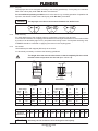
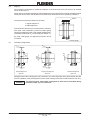
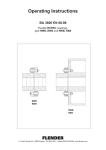
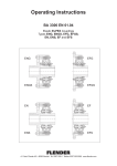
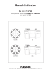
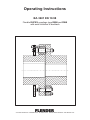
Operating Instructions
BA 3601 EN 10.98
Flexible RUPEX couplings type RWN and RWS
with axial limitation of backlash
A. Friedr. Flender AG ⋅ 46393 Bocholt ⋅ Tel. 02871/92-0 ⋅ Telefax 02871/92-2596 ⋅ www.flender.com
Contents
1.
Technical data
4
1.1
1.2
Validity of the nominal torques
Types RWN and RWS with axial limitation of backlash
4
4
2.
General notes
6
2.1
General
6
3.
Safety notes
7
3.1
3.1.1
Safety notes
Notes and symbols in the operating instructions
7
7
4.
Handling and storage
8
4.1
4.2
4.3
4.3.1
4.3.2
4.3.2.1
4.3.2.2
Scope of supply
Handling
Storage
Storage of the coupling parts
Storage of the buffers
General
Storage room
8
8
8
8
8
8
8
5.
Technical description
9
5.1
General description
9
6.
Assembly
10
6.1
6.1.1
6.1.1.1
6.1.2
6.1.3
6.1.4
6.2
6.3
6.4
6.5
6.6
6.7
6.7.1
6.7.2
6.7.3
6.8
6.9
Notes on fitting the finished bore, the axial securing, the set screws, the balancing
Finished bore
Keyway
Axial securing
Set screws
Balancing
General installation notes
Mounting the coupling parts 1/2 for attachment by set screw
Mounting the coupling parts 1/2 for attachment using end plates
Mounting the coupling parts 1/2 in case of absolutely tight fit
Aligning
Possible misalignments
Axial misalignment
Angular misalignment
Radial misalignment
Setting the axial-backlash limitation
Assignments of the tightening torques
10
10
11
11
11
12
12
13
14
15
16
16
17
17
17
17
18
7.
Startup
18
7.1
Measures before startup
18
8.
Operation
18
8.1
General operating data
18
9.
Disturbances, reasons and remedy
19
9.1
9.2
General
Possible malfunctions
19
19
BA 3601 EN 10.98
10.
Maintenance and repair
20
10.1
10.2
General
Change of wear parts
20
20
11.
Spare parts stock, service facility addresses
21
11.1
Service facility addresses
21
12.
Declaration by the manufacturer
26
BA 3601 EN 10.98
1.
Technical data
1.1
Validity of the nominal torques
Validity of nominal torques TKN (with original RUPEX buffer of buna N, hardness 80 Shore only):
S daily operating cycle up to 24 h
S during the starting process or during operation, torque impulses up to the triple nominal torque are
allowed up to 25 times per hour.
S Operation within the prescribed alignment
S Operation in the temperature range from - 30 °C to + 80 °C (ambient temperature or temperature of
the shaft ends).
For permanent trouble-free operation, the coupling has to be designed with a
service factor appropriate to the respective application. When changing the
operating conditions (performance, speed, changes on power engine and
machine), a check of the design is absolutely necessary.
Caution!
Types RWN and RWS with axial limitation of backlash
w1
u
S1
S1
u
u
2
l
Size 285 - 360
Size 400
u
u
S1
S1
u
u
1
2
1
2
l
Size 450 - 500
D1
d2
da
d2
l
D1
D1
d2
l
da
d2
l
D1
d2
da
d2
D1
l
D1
d2
da
l
1
d2
2
D1
1
D1
1.2
v
l
v
v
Size 560 - 1250
BA 3601 EN 10.98
v
Nominal
torque
TKN
Size
Speed
nmax
Bore
from
Weight
to
1)
RWN
RWS
RWN
Nm
1/min
1/min
D1/2
mm
D1
mm
D2
mm
da
l
v
P
S1
w1
u
RWS
RWN
RWS
Part 1 Part 2 Part 1 Part 2
D1
mm
D2
mm
mm
d1
mm
d2
mm
mm
mm
mm
mm
mm
mm
2)
kg
2)
kg
2)
kg
2)
kg
285
4300
2400
3900
48
100
110
110
120
285
164
175
110
60
3... 6
30
32
16
23
17.5
25
320
5500
2100
3500
55
110
120
125
130
320
180
192
125
60
3... 6
30
32
23
30
25
32
360
7800
1900
3100
65
120
130
135
140
360
200
210
140
75
3... 6
42
42
32
46
35
50
400
12500
1700
2800
75
140
140
150
150
400
230
230
160
75
3... 6
42
53
53
57
57
450
18500
1500
2500
85
160
160
170
170
450
260
260
180
90
4... 7
52
78
78
84
84
500
25000
1350
2200
95
180
180
190
190
500
290
290
200
90
4... 7
52
99
99
105
105
560
39000
1200
100
2000 > 140
> 180
140
180
200
140
180
200
165
200
210
165
200
210
560
250
300
320
250
300
320
220
70
120
4... 8
68
140
145
145
140
145
145
150
155
155
150
155
155
630
52000
1050
100
1800 > 140
> 180
140
180
220
140
180
220
165
200
235
165
200
246
630
250
300
355
250
300
355
240
80
120
4... 8
68
175
185
200
175
185
200
190
200
215
190
200
215
710
84000
950
110
1600 > 160
> 200
160
200
240
160
200
240
190
220
250
190
220
250
710
290
330
385
290
330
385
260
80
140
5... 9
80
255
260
270
255
260
270
275
280
290
275
280
290
800
110000
850
125
1400 > 180
> 220
180
220
260
180
220
260
210
240
280
210
240
280
800
320
360
420
320
360
420
290
90
140
5... 9
80
330
350
360
330
350
360
360
380
390
360
380
390
900
150000
750
1250
140
> 180
> 220
> 260
180
220
260
290
180
220
260
290
210
240
280
310
210
240
280
310
900
320
360
425
465
320
360
425
465
320
100
160
5...10
90
450
450
480
510
450
450
480
510
490
490
520
550
490
490
520
550
1000
195000
680
1100
150
> 200
> 240
> 280
200
240
280
320
200
240
280
320
230
260
300
340
230
260
300
340
1000
355
395
460
515
355
395
460
515
350
110
160
5...10
90
560
580
630
660
560
580
630
660
610
630
680
710
610
630
680
710
1120
270000
600
1000
160
> 200
> 250
> 300
200
250
300
350
200
250
300
350
240
270
330
370
240
270
330
370
1120
360
410
495
560
360
410
495
560
380
120
180
6...11
100
730
750
800
840
730
750
800
840
790
810
870
910
790
810
870
910
1250
345000
550
900
180
> 230
> 280
> 330
230
280
330
380
230
280
330
380
270
300
360
400
270
300
360
400
1250
410
460
540
610
410
460
540
610
420
130
180
6...11
100
920
950
1000
1100
920
950
1000
1100
1000
1050
1050
1150
1000
1050
1050
1150
Table 1.1: Torques TKN, speeds nmax, sizes and weights
1) Observe the validity of the nominal torques TKN according to 1.1!
2) Weights are valid for max. bores.
BA 3601 EN 10.98
2.
General notes
2.1
General
These Operating Instructions constitute part of the coupling shipment and should be kept in the
immediate vicinity of the coupling at all times.
Only a precise knowledge of the Operating Instructions will ensure trouble-free operation of the
coupling. It is therefore in the interest of our customer that the operating instructions are read,
understood and observed in all respects by the persons responsible for handling, installation and
operation.
Note:
We accept no liability for any damage or malfunction resulting from non-observance
of the operating instructions.
The ”coupling” dealt with in these operating instructions was developed for stationary use in general
engineering.
The coupling is only designed for the field of application as specified in Section 1 ”Technical data”.
Operating conditions which differ from the stated will require fresh contractual agreements.
The coupling described here is in accordance with the state of the art at the time of these operating
instructions go into print.
In the interest of further development, we reserve the right to introduce modifications which, while
retaining the essential features, can be regarded as desirable to increase its efficiency and safety.
The copyright of these Operating Instructions remains the property of FLENDER AG.
These operating instructions may not be duplicated in part or whole, utilized for the purpose of publicity
or communicated to third parties without our expressed consent.
Please contact our works listed below in respect of all technical queries.
FLENDER AG
D 46393 Bocholt
Telephone: 02871/92-2800
Telefax:
02871/92-2801
or one of our service branches which are listed in Section 11 ”Stocking spare parts, service facility
addresses”.
BA 3601 EN 10.98
3.
Safety notes
3.1
Safety notes
S The coupling is constructed in accordance with the state of the art and is reliable in the condition as
shipped. Unauthorized modifications which impair its reliability are not permissible. This also applies
to guards which are fitted as protection against accidental contact.
S The coupling may only be used and operated within the scope of the condition specified in the contract
of performance and supply.
S The customer should ensure that the persons entrusted with installation, operation, care and
maintenance as well as repair have read and understood the operating instructions and observe them
in all respects in order to:
– prevent hazard to life and limb of the user and third parties
– ensure the reliability of the coupling
and
– prevent failure and environmental pollution due to incorrect handling.
S The relevant regulations concerning industrial safety and pollution control should be observed during
handling, installation, operation as well as care and maintenance.
S The coupling may only be operated, serviced and repaired by authorized, trained and properly
instructed personnel.
S All work should be carried out with care with the safety aspect in mind.
S All work on the coupling may only be carried out when it is stationary.
The coupling must be secured to prevent accidental start up (e.g. by locking the key switch or by
removing the fuses and the power supply). A notice should be displayed at the switch-on point stating
that work is in progress on the coupling.
S The drive unit should be shut off at once if changes in the coupling are detected during operation, such
as e.g. changed running noises.
S The coupling must be protected by means of suitable guards to prevent accidental contact.
S During installation of the coupling in units or systems, the manufacturer of the units or systems is
obliged to incorporate the requirements, notes and descriptions contained in these operating
instructions in his own operating instructions.
3.1.1
Notes and symbols in the operating instructions
Instructions in the operating instructions which concern operating safety are emphasized as follows:
This symbol draws attention tosafety measures which must be observed to prevent
personal injury.
Caution!
Note:
This symbol draws attention to safety measures which must be observed to prevent
damage to the coupling.
This note draws attention to general operating notes which should be especially
observed.
BA 3601 EN 10.98
4.
Handling and storage
4.1
Scope of supply
The scope of the shipment is listed in the shipping documents. They should be checked for
completeness on receipt. Any shipping damage and/or missing parts should be reported in writing at
once. After consulting FLENDER an expert is to be called in.
4.2
Handling
The packing of the coupling will differ depending on method of shipment and size. The packing, unless
otherwise agreed contractually, complies with HPE Packing Guidelines.
The symbols shown on the packing should be noted. Their meaning is as follows:
bild-transport
This way
up
Caution!
Fragile
Keep
dry
Keep
cool
Centre of
gravity
Use no
hand hook
Attach
here
Make sure that suitable hoists are used.
4.3
Storage
4.3.1
Storage of the coupling parts
The coupling is delivered in a preserved state and can be stored at a covered dry place up to 6 months.
If the coupling shall be stored for a longer period of time, an appropriate long-term preservation is
necessary (consultation with FLENDER required).
Caution!
4.3.2
Before cleaning the coupling parts and applying the long-term preservation,
the buffers are to be removed.
Storage of the buffers
4.3.2.1 General
Properly stored buffers keep their characteristics for up to 5 years. Unfavourable storage conditions and
improper treatment of the buffers result in a negative change of the physical characteristics. These
changes can be caused by the effects of e.g. ozone, extreme temperatures, light, moisture or solvents.
4.3.2.2 Storage room
The storage room should be dry and dust-free. The buffers must not be stored together with chemicals,
solvents, fuels, acids, etc. Furthermore, they should be protected against light, especially against direct
sun light and strong artificial light with a high ultra-violet percentage.
Caution!
The storage romms must not contain any ozone-producing devices like e.g.
fluorescent light sources, mercury-vapour lamps, electric high-voltage
devices. Damp storage rooms are unsuitable. Make sure that no condensation
develops. The relative humidity of air is most favourable below 65 %.
BA 3601 EN 10.98
5.
Technical description
5.1
General description
1
32
31
6
5
30
8
11
2
7
Bolted joint of sizes
285-400
35
33
34 35
4, 6
The RUPEX coupling consists of two coupling parts and the pin with the flexible plastic buffers required
for transmitting the torque. The type with axial limitation of backlash is also fitted with the ring (31)
and headless pin with nuts (33-35).
Up to size 360, the ground steel bolts are attached to the buffers only in the coupling part (2). From size
400 they are attached alternately in the coupling parts (1 and 2). In the assembled state, the buffers
engage the buffer bores of the counterpart.
The flexible plastic buffers of buna N have a hardness of 80 Shore. Buffers of differing material quality
and/or hardness are available within limits. With regard to the availability of these special buffers and
the extent to which the properties of the coupling are affected, please consult FLENDER.
RUPEX couplings with limited axial backlash are used in applications where the motor has no axial
bearing of its own.
BA 3601 EN 10.98
6.
Assembly
6.1
Notes on fitting the finished bore, the axial securing, the set screws, the balancing
6.1.1
Finished bore
S Remove buffers.
S Remove the anti-corrosion agent from coupling parts 1/2
Observe manufacturer’s instructions on handling solvents.
When fitting the finished bore, align the parts carefully. For the permissible radial and axial excentricity
see DIN ISO 286 degree of fundamental tolerance IT8. The location of the parts (
) is to be carried
out on the marked surfaces.
Caution!
The maximum permissible boring diameters (see Section 1.) are designed for
driving connections without tightening according to DIN 6885/1 and must not
be exceeded in any case.
If other shaft hub connections (e.g. splined hub profile, tapered or graded bore, driving connection with
tightening, etc.) shall be fitted instead of the intended driving connections, FLENDER is to be consulted.
Non-observance of these notes may lead to the drifting of coupling.
There is a danger to life due to broken pieces flying around!
D1
A
3.2
IT8 A
In case of drive by means of parallel keys, the following fit pairings are prescripted for the bores:
Shaft end tolerances
k6
m6
n6
Boring
Tolerances
Diameter in mm
≤ 50
J7
> 100
≤ 100
J7
J7
Table 6.1: Fit pairings
Caution!
This arrangement applies for axial attachment with set screw (up to size 360
only) or for end-plate attachment with locking screws.
Observing the fit correspondance is absolutely necessary, on the one hand in
order to keep low the backlash in the shaft hub connection or, on the other
hand, to keep the hub tension caused by the overdimension within the
permissible load depending on the use of the tolerance fields. It cannot be
excluded, that the shaft hub connection is endangered when the fit
correspondance is not observed.
For an absolutely tight fit, consult FLENDER.
Non-observance of these notes may lead to the bursting of the coupling.
There is a danger to life due to broken pieces flying around!
BA 3601 EN 10.98
6.1.1.1 Keyway
The keyways have to be designed according to the existing parallel keys. For keyways, the tolerance
field of the hub keyway width ISO JS 9 is to be observed.
For more difficult operating conditions, as it is the case for e.g. reversing operation of operation with
impulses, the tolerance filed of the hub keyway width ISO P9 is prescribed.
The keyways are to be set and centered between the buffer bores.
Caution!
6.1.2
Axial securing
For axial attachment of the coupling parts up to size 360, a set screw may be used.
From size 400 onwards, the coupling parts should be secured against axial shift on the machine shafts
by means of an absolutely tight fit or by end plates with locking screws. If end plates are being used,
FLENDER should be consulted on applying the recess in the coupling parts.
Set screws
Use headless pins with tappets (DIN 915) as set screw.
It is absolutely necessary to observe the following guidelines!
The length of the set screw is to be chosen so that it completely fills the cut hole
but that it does not protect over the hub (Lmin = d1 x 1.2).
e1
d1
d1
t
6.1.3
d2
Type RWN
Bore range
above
to
mm
mm
Type RWS
d1
d2
t
mm
mm
mm
Bore range
above
to
mm
mm
d1
d2
t
mm
mm
mm
48
65
M10
7
2.5
48
75
M 8
5.5
2
65
95
M12
8.5
3
75
95
M12
8.5
3
95
110
M16
12
4
95
110
M16
12
4
110
140
M20
15
5
110
150
M20
15
5
Table 6.2: Set screw assignment
Size
285
320
360
400
450
500
560
630
710
800
900
1000
1120
1250
Distance
55
dimension e1
60
70
80
80
90
100
110
130
115
160
175
160
200
Table 6.3: Distance dimensions of the set screws
Caution!
Generally, the set screws are to be arranged on the keyway.
BA 3601 EN 10.98
6.1.4
Balancing
Prebored couplings resp. prebored coupling parts are shipped unbalanced. For these parts et is
recommended to balance them depeding on the application case after finish boring (see also DIN 740,
VDI guideline 2060).
Balancing is usually carried out by material cutting through boring. In order ro restrict the material
quantity to be cut to a minium, the biggest possible balancing radius is to be selected.
Caution!
For parts 1/2, cutting has to be carried out between the bores without
through-boring of the bottom.
Finished bored couplings or coupling parts are balanced according to the instructions of the ording
party.
Balancing bore
Arrangement of the balancing bore
in case of one level balancing
6.2
Arrangement of the balancing bore
in case of two level balancing
General installation notes
For the installation the safety notes in Section 3. are to be observed.
The installation has to be carried out with utmost care by trained personnel.
Already during the planning phase it is to be observed that sufficient room is to be provided for the
installation and later inspection and maintenance work.
Before starting the installation a sufficient number of hoists must be provided for.
BA 3601 EN 10.98
6.3
Mounting the coupling parts 1/2 for attachment by set screw
Before starting the assembly, the shaft ends as well as the coupling parts have to be cleaned thoroghly.
Before cleaning the coupling parts with solvents, remove the buffers.
Observe the manufactuer’s instructions on handling the solvents.
Caution!
Before mounting the coupling part 1 on the motor shaft, place the locking ring
(31) on the hub of coupling part 1.
Caution!
Mount coupling parts 1/2 using suitable equipment to prevent the shaft bearing
from being damaged by the axial forces during assembly.
Make sure that suitable hoists are used.
Warming up the coupling parts (to max. +150 °C) might make the fitting easier. In case of temperatures
above +80 °C, the buffers/bolts have to be removed from the coupling parts before warming up.
Protect yourself against burns by hot parts!
Allow the coupling parts 1/2 to cool down to +30 °C.
Spot-drill the parallel key in the motor shaft through the existing hole for the set screw acc. to item 6.1.3.
Carefully remove all dirt and contamination from the coupling parts.
Caution!
Tightening of the set screws only by means of a hexgon socket head wrench
according to DIN 911, without an extension pipe.
Non-observance of these notes may lead to the burrsting of the coupling.
There is danger to life due to broken pieces flying around!
Install the bolt (4) with disk (6) and buffer (5) in coupling part 1.
Caution!
Pay close attention to markings.
Tighten nuts (7) or bolts (11) using a torque wrench (for correct torques see section 6.9).
Install the bolt (30) with disk (6) and buffer (5) in coupling part 2.
Caution!
Pay close attention to markings.
Tighten nuts (7) or bolts (11) using a torque wrench (for correct torques see section 6.9).
Determine the axial backlash of the electric motor in order to obtain the position of the machines being
coupled. Half the actual backlash indicates the temporary position of the motor shaft in relation to the
machine shaft and must be within the permitted deviation for dimension S1 (see section 1).
Loop together the machines to be coupled.
Danger of squeezing!
Mount the locking ring (31) and bolt (30) with the bolts (32).
Caution!
Pay close attention to markings
Tighten the bolts (32) (see section 6.9 for correct torques) and secure them with a few spots of adhesive
(e.g. Loctite type 242).
BA 3601 EN 10.98
6.4
Mounting the coupling parts 1/2 for attachment using end plates
Before starting the assembly, the shaft ends as well as the coupling parts have to be cleaned thoroghly.
Before cleaning the coupling parts with solvents, remove the buffers.
Observe the manufactuer’s instructions on handling the solvents.
Caution!
Before mounting the coupling part 1 on the motor shaft, place the locking ring
(31) on the hub of coupling part 1.
Caution!
Mount coupling parts 1/2 using suitable equipment to prevent the shaft bearing
from being damaged by the axial forces during assembly.
Make sure that suitable hoists are used.
Warming up the coupling parts (to max. +150 °C) might make the fitting easier. In case of temperatures
above +80 °C, the buffers/bolts have to be removed from the coupling parts before warming up.
Protect yourself against burns by hot parts!
Allow the coupling parts 1/2 to cool down to +30 °C.
Position the end plates and screw them to the shaft end by means of locking screws.
Install the bolt (4) with disk (6) and buffer (5) in coupling part 1.
Caution!
Pay close attention to markings.
Tighten nuts (7) or bolts (11) using a torque wrench (for correct torques see section 6.9).
Install the bolt (30) with disk (6) and buffer (5) in coupling part 2.
Caution!
Pay close attention to markings.
Tighten nuts (7) or bolts (11) using a torque wrench (for correct torques see section 6.9).
Determine the axial backlash of the electric motor in order to obtain the position of the machines being
coupled. Half the actual backlash indicates the temporary position of the motor shaft in relation to the
machine shaft and must be within the permitted deviation for dimension S1 (see section 1).
Loop together the machines to be coupled.
Danger of squeezing!
Mount the locking ring (31) and bolt (30) with the bolts (32).
Caution!
Pay close attention to markings
Tighten the bolts (32) (see section 6.9 for correct torques) and secure them with a few spots of adhesive
(e.g. Loctite type 242).
BA 3601 EN 10.98
6.5
Mounting the coupling parts 1/2 in case of absolutely tight fit
Caution!
Remove the bolt and buffer from the coupling part 1/2.
Before starting the assembly, the shaft ends as well as the coupling parts have to be cleaned thoroghly.
Before cleaning the coupling parts with solvents, remove the buffers.
Observe the manufactuer’s instructions on handling the solvents.
Caution!
Before mounting the coupling part 1 on the motor shaft, place the locking ring
(31) on the hub of coupling part 1.
The coupling parts 1/2 must be mounted warm and must be heated to the temperature stated in the
dimensional drawing to obtain the correct amount of shrinkage.
They can be heated either inductively, with a burner, or in a furnace.
Protect yourself against burns by hot parts!
Caution!
The heated coupling parts (1/2) are to be fitted by means of suitable devices in
order to prevent damage to the shaft bearing by the axial fitting force.
Make sure that suitable hoists are used.
Push the coupling parts 1/2 onto the shaft without delay, up to the point where the shaft surface and
the front side of the coupling are aligned.
Note:
Fix the coupling parts 1/2 to the shaft with a suitable fastening device until they have
cooled and fit tightly on the shaft.
Allow the coupling parts 1/2 to cool down to +30 °C.
Install the bolt (4) with disk (6) and buffer (5) in coupling part 1.
Caution!
Pay close attention to markings.
Tighten nuts (7) or bolts (11) using a torque wrench (for correct torques see section 6.9).
Install the bolt (30) with disk (6) and buffer (5) in coupling part 2.
Caution!
Pay close attention to markings.
Tighten nuts (7) or bolts (11) using a torque wrench (for correct torques see section 6.9).
Determine the axial backlash of the electric motor in order to obtain the position of the machines being
coupled. Half the actual backlash indicates the temporary position of the motor shaft in relation to the
machine shaft and must be within the permitted deviation for dimension S1 (see section 1).
Loop together the machines to be coupled.
Danger of squeezing!
Mount the locking ring (31) and bolt (30) with the bolts (32).
Caution!
Pay close attention to markings
Tighten the bolts (32) (see section 6.9 for correct torques) and secure them with a few spots of adhesive
(e.g. Loctite type 242).
BA 3601 EN 10.98
6.6
Aligning
The couplings compensate for positional variations of the shaft ends to be connected up to the data
shown under item 6.7.
When aligning, keep the radial and angular misalignment of the shaft ends as small as possible because
hereby the service life of the flexible is increased under otherwise the same operating conditions.
Ruler
The alignment should be realised in the order:
1. angular alignment
2. radial alignment
and should be carried out in two axial planes vertical to
each other. This is possible by means of a feeler gauge
(angular misalignment) and a ruler (radial misalignment).
The distance dimension S1 is to be kept (see Section 1.).
By using a dial gauge, the alignment precision can be
increased.
Feeler gauge
Possible misalignments
S1max
D Kr
S1max
DKa
D Kw
6.7
S1min
S1min
Axial misalignment
figure 6.1
Angular misalignment
figure 6.2
Radial misalignment
figure 6.3
Misalignments of the coupling parts may result from an inexact alignment during the assembly but also
from the operation of the plant (expansion due to heat, bending of the shaft, machine frame to soft, etc.).
Caution!
The following max. permissible misalignments must not be exceeded during
operation under any circumstances.
BA 3601 EN 10.98
6.7.1
Axial misalignment
With due regard to the instructions given in 6.8,
axial misalignment ∆Ka (fig. 6.1) of the
coupling parts to one another is allowed within
the permissible deviation for dimension S1
(see section 1).
Angular misalignment
The permissible angular misalignment DKw
(figure 6.2) has to be determined taking into
consideration the speed factor Sn of figure 6.4.
DKwperm. =S1 max - S1 min = 0.00175 x da x Sn
(da = Coupling size)
6.7.3
Size
6.7.2
Speed factor
Sn max = 1.5
Radial misalignment
The permissible radial misalignment DKr
(figure 6.3) has to be determined taking into
consideration the speed factor Sn of figure 6.4.
DKrperm. = 0.00175 da Sn
(da = Coupling size)
Caution!
6.8
Speed n [1/min]
figure 6.4
Angular and radial misalignments may occur at the same time. The sum of both
misalignments must not exceed the max. permissible value of the angular or
radial misalignment.
(Kw + Kr)existing ≤ DKw x Sn or DKr x Sn
Setting the axial-backlash limitation
The axial-backlash limitation on the RUPEX coupling must be less than the axial backlash calculated
for the electric motor.
Using the set screws (33, 34), set the axial-backlash of the RUPEX coupling to approximately half the
figure calculated for the motor. The coupling backlash must be within the figure permitted for S1.
Example:
Axial backlash of motor
= 8 mm
Axial backlash of coupling
= 4 mm
Axial backlash to be set for each coupling part (dimension*) = 2 mm
*
As the centre of the rotor axial backlash is not necessarily
identical with the magnetic centre of the motor, many electric
motors have a mark on the shaft. When this mark is aligned with
the outer surface of the bearing cover, this corresponds to the
magnetic centre of the rotor.
In the case of motors without this mark, the magnetic centre
should be determined through a test run.
In this operating position, the axial backlash set on the RUPEX
coupling must be equal on both sides (dimension*) to prevent
axial forces affecting the machine bearings. When the setting
operation is complete, tighten the counter nuts (35).
Caution!
*
The axial backlash set must be large enough to allow the RUPEX coupling to
compensate for the angular deviation.
BA 3601 EN 10.98
6.9
Assignments of the tightening torques
Tightening torque TA
Size
Wrench width SW
Part 7, 11
Part 32
Part 7, 11
Part 32
Nm
Nm
mm
mm
285
150
60
24
17
320
150
60
24
17
360
220
105
27
19
400
220
105
27
19
450
180
255
24
24
500
180
255
24
24
560
340
500
30
30
630
340
500
30
30
710
580
870
36
36
800
580
870
36
36
900
600
870
36
36
1000
600
870
36
36
1120
1150
1750
46
46
1250
1150
1750
46
46
Table 6.4: Assignments of the tightening torques
7.
Startup
7.1
Measures before startup
Before start-up, check the tension of the set screws, as well as the alignment, axial-backlash limitation,
and clearance S1, and if necessary correct them. In addition, check that all bolted joints have been
tightened to the specified torque (see sections 1 and 6). Finally, the coupling guard to prevent accidental
contact is to be fixed.
8.
Operation
8.1
General operating data
During operation, the coupling should be checked for:
– any changes in running noises
– sudden shaking.
Caution!
If irregularities are detected during operation, the drive assembly should be set
off immediately. The cause of the malfunction should be determined with the
aid of the Troubleshooting Table (Section 9.).
The Troubleshooting Table lists possible malfunctions, their causes and
suggestions for remedying them.
If the cause cannot be determined or there is no facility for repair with suitable
equipment, we recommend calling in one of our service fitters (see Section 11.).
BA 3601 EN 10.98
9.
Disturbances, reasons and remedy
9.1
General
The malfunctions listed below can only be hints for a troubleshooting.
In case of a complex plant, all other components have always to be included in the troubleshooting.
The coupling has to run with low noise and without shaking in all operating phases. Any deviating
behaviour is to be regarded as malfunction and should be repaired immediately.
Before maintenance work, repairs or other work, the operator should make sure
that the whole drive train is stationary. Especially the drive motors are to be
secured against accidental start up.
Futhermore, we refer to the relevant regulations on the prevention of accidents
at the place of installation.
9.2
Possible malfunctions
Malfunctions
Sudden change of the noise
level and/or sudden shaking
Causes
Change of alignment
Remedy
Shut down the plant
possibly repair the reason for
the change of alignment
(e.g. fasten loose foundation bolts)
Buffers worn,
no dampening
Shut down the plant
Disassemble coupling and remove
the rests of the buffers
Check coupling parts and
exchange damaged coupling parts
Buffers are to be changed in sets
Check alignment and correct
if necessary, see Section 6.
Assembly of coupling acc.
to Section 6. ”Assembly”
and Section 7. ”Start up”.
BA 3601 EN 10.98
10.
Maintenance and repair
10.1
General
The circumferential backlash between the two coupling parts should be checked according to the
maintenance intervals, however, at least once a year. As far as an increased backlash of the coupling
is not detrimental to the operation of the coupling, the elastic buffers may remain in use until a defined
wear limit is reached before they should be changed. For evaluating the wear, in Table 10.1, the
permissible circumferential backlash is listed, which is converted to the chord dimension DSV on the
outer coupling diameter. In order to determine the dimension DSV, a coupling part is turned until stop
without torque and a mark is made on the coupling part (see figure 10.1). By turning the coupling part
in the opposite direction of rotation until stop, the marks move apart. The distance between the marks
is the chord dimension DSV. If the dimension DSV exceeds the value listed in Table 10.1, the buffers
should be changed.
The buffers should be changed in sets.
D SV
Caution!
figure 10.1
Size
285 / 320
360 / 400
450 / 500
560 / 630
710 / 800
DSV
6.0
7.0
8.5
10.0
12.0
900 / 1000 1120 / 1250
13.5
15.0
Table 10.1: Wear mark
10.2
Change of wear parts
Only use original Rupex buffers as spare buffers, in order to guarantee a perfect transmission of the
torque and a trouble-free function.
Carefully observe the instructions of Section 6. ”Installation” and Section 7. ”Start up” for the
re-installation.
BA 3601 EN 10.98
11.
Spare parts stock, service facility addresses
Maintaining a stock of the most essential spare and wear parts is an important prerequisite for the
permanent service ability of the coupling.
When ordering spare parts, the following data should be stated:
– Part No. (see Section 5.)
– Description / Size (the size designation corresponds to the outer diameter da in mm)
– Quantity
We assume warranty only for original spare parts supplied by us.
Caution!
We would expressly draw attention to the fact that spare parts and accessories
not supplied by us have not been tested or approved by us either. Fitting and/or
use of such products can therefore under certain circumstances adversely
affect structurally specified properties of the coupling and will thus impair
active and/or passive safety. No form of reliability or warranty will be assumed
by FLENDER for damage occasioned by use of non-original spare parts and
accessories.
Please note that production and supply specifications frequently exist for components and we will
always offer spare parts in accordance with the state of the art and in accordance with the latest legal
requirements.
11.1
Service facility addresses
When ordering spare parts or requesting a service fitter, please contact FLENDER AG first of all.
FLENDER Germany
A. FRIEDR. FLENDER AG
46393 Bocholt - Tel.: (0 28 71) 92-0 - Fax: (0 28 71) 92 25 96
E-mail: [email protected] S www.flender.com
Shipping address: Alfred - Flender - Strasse 77 - 46395 Bocholt
A. FRIEDR. FLENDER AG - Kupplungswerk Mussum
Industriepark Bocholt - Schlavenhorst 100 - 46395 Bocholt - Tel.: (0 28 71) 92 28 68 - Fax: (0 28 71) 92 25 79
E-mail: [email protected] S www.flender.com
A. FRIEDR. FLENDER AG - Werk Friedrichsfeld
Am Industriepark 2 - 46562 Voerde - Tel.: (0 28 71) 92-0 - Fax: (0 28 71) 92 25 96
E-mail: [email protected] S www.flender.com
A. FRIEDR. FLENDER AG - Getriebewerk Penig
Thierbacher Strasse 24 - 09322 Penig - Tel.: (03 73 81) 60 - Fax: (03 73 81) 8 02 86
E-mail: [email protected] S www.flender.com
FLENDER - TÜBINGEN GMBH
72007 Tübingen - Tel.: (0 70 71) 7 07-0 - Fax: (0 70 71) 70 74 00
E-mail: [email protected] S www.flender.com
Shipping address: Bahnhofstrasse 40 - 72072 Tübingen
LOHER GMBH
94095 Ruhstorf - Tel.: (0 85 31) 3 90 - Fax: (0 85 31) 3 94 37
E-mail: [email protected] S www.loher.de
Shipping address: Hans-Loher-Strasse 32 - 94099 Ruhstorf
FLENDER SERVICE GMBH
44607 Herne - Tel.: (0 23 23) 940-0 - Fax: (0 23 23) 940 333
E-mail: [email protected] S www.flender-service.com
24h Service Hotline +49 (0) 17 22 81 01 00
Shipping address: Südstrasse 111 - 44625 Herne
A. FRIEDR. FLENDER AG - FLENDER GUSS
Obere Hauptstrasse 228-230 - 09228 Chemnitz / Wittgensdorf - Tel.: (0 37 22) 64-0 - Fax: (0 37 22) 64 21 89
E-mail: [email protected] S www.flender-guss.de
BA 3601 EN 10.98
Germany
A. FRIEDR. FLENDER AG
46393 BOCHOLT - TEL.: (0 28 71) 92 - 0 - FAX: (0 28 71) 92 25 96
SHIPPING ADDRESS: ALFRED - FLENDER - STRASSE 77 - 46395 BOCHOLT
––––––––––––––––––––––––––––––––––––––––––––––––––––––––––––––
E-mail: [email protected]
S
www.flender.com
––––––––––––––––––––––––––––––––––––––––––––––––––––––––––––––
VERTRIEBSZENTRUM BOCHOLT
46393 Bocholt
Alfred-Flender-Strasse 77, 46395 Bocholt
Tel.: (0 28 71) 92 - 0
Fax: (0 28 71) 92 - 14 35
E-mail: [email protected]
___________________________________________________________________________________________________________
VERTRIEBSZENTRUM STUTTGART
70472 Stuttgart
Friolzheimer Strasse 3, 70499 Stuttgart
Tel.: (07 11) 7 80 54 - 51
Fax: (07 11) 7 80 54 - 50
E-mail: [email protected]
___________________________________________________________________________________________________________
VERTRIEBSZENTRUM MÜNCHEN
85750 Karlsfeld
Liebigstrasse 14, 85757 Karlsfeld
Tel.: (0 81 31) 90 03 - 0
Fax: (0 81 31) 90 03 - 33
E-mail: [email protected]
___________________________________________________________________________________________________________
VERTRIEBSZENTRUM BERLIN
Schlossallee 8, 13156 Berlin
Tel.: (0 30) 91 42 50 58
Fax: (0 30) 47 48 79 30
E-mail: [email protected]
___________________________________________________________________________________________________________
BA 3601 EN 10.98
FLENDER International
EUROPE
AUSTRIA
Flender Ges.m.b.H.
Industriezentrum Nö-Süd
Strasse 4, Objekt 14, Postfach 132
2355 Wiener Neudorf
Phone: +43 (0) 22 36 6 45 70
Fax: +43 (0) 22 36 6 45 70 10
E-mail: [email protected]
www.flender.at
BELGIUM & LUXEMBOURG
N.V. Flender Belge S.A.
Cyriel Buyssestraat 130
1800 Vilvoorde
Phone: +32 (0) 2 - 2 53 10 30
Fax: +32 (0) 2 - 2 53 09 66
E-mail: [email protected]
(2003-12-01)
Flender - Graffenstaden SA
1, rue du Vieux Moulin
67400 Illkirch-Graffenstaden
B.P. 84
67402 Illkirch - Graffenstaden
Phone: +33 (0) 3 - 88 67 60 00
Fax: +33 (0) 3 - 88 67 06 17
E-mail: [email protected]
GREECE
Flender Hellas Ltd.
2, Delfon str., 11146 Athens
Phone: +30 210 - 2 91 72 80
Fax: +30 210 - 2 91 71 02
E-mail: [email protected]
Mangrinox S.A.
14, Grevenon str., 11855 Athens
Phone: +30 210 - 3 42 32 01
Fax: +30 210 - 3 45 99 28
E-mail: [email protected]
BULGARIA
A. Friedr. Flender AG
Branch Office
c/o Auto - Profi GmbH
Alabin Str. 52, 1000 Sofia
Phone: +359 (0) 2 - 9 80 66 06
Fax: +359 (0) 2 - 9 80 33 01
E-mail: [email protected]
HUNGARY
A. Friedr. Flender AG
Branch Office
Bécsi Út 3-5, 1023 Budapest
Phone: +36 (0) 1 - 3 45 07 90 / 91
Fax: +36 (0) 1 - 3 45 07 92
E-mail: [email protected]
CROATIA / SLOVENIA
BOSNIA-HERZEGOVINA
A. Friedr. Flender AG
Branch Office
c/o HUM - Naklada d.o.o.
Mandroviceva 3, 10000 Zagreb
Phone: +385 (0) 1 - 2 30 60 25
Fax: +385 (0) 1 - 2 30 60 24
E-mail: [email protected]
ITALY
Flender Cigala S.p.A.
Parco Tecnologico Manzoni
Palazzina G
Viale delle industrie, 17
20040 Caponago (MI)
Phone: +39 (0) 02 - 95 96 31
Fax: +39 (0) 02 -95 74 39 30
E-mail: [email protected]
CZECH REPUBLIC
A. Friedr. Flender AG
Branch Office
Hotel DUO, Teplicka 17
19000 Praha 9
Phone: +420 (0) 2 - 83 88 23 00
Fax: +420 (0) 2 - 83 88 22 05
E-mail: [email protected]
THE NETHERLANDS
Flender Nederland B.V.
Industrieterrein Lansinghage
Platinastraat 133
2718 ST Zoetermeer
Postbus 725
2700 AS Zoetermeer
Phone: +31 (0) 79 - 3 61 54 70
Fax: +31 (0) 79 - 3 61 54 69
E-mail: [email protected]
www.flender.nl
DENMARK
Flender Scandinavia A/S
Rugmarken 35 B, 3520 Farum
Phone: +45 - 70 22 60 03
Fax: +45 - 44 99 16 62
E-mail: [email protected]
www.flenderscandinavia.com
ESTHONIA / LATVIA / LITHUANIA
Flender Branch Office
Addinol Mineralöl Marketing OÜ
Suur-Söjamäe 32
11415 Tallinn / Esthonia
Phone: +372 (0) 6 - 27 99 99
Fax: +372 (0) 6 - 27 99 90
E-mail: [email protected]
www.addinol.ee
FINLAND
Flender Oy
Ruosilantie 2 B, 00390 Helsinki
Phone: +358 (0) 9 - 4 77 84 10
Fax: +358 (0) 9 - 4 36 14 10
E-mail: [email protected]
www.flender.fi
FRANCE
Flender s.a.r.l.
3, rue Jean Monnet - B.P. 5
78996 Elancourt Cedex
Phone: +33 (0) 1 - 30 66 39 00
Fax: +33 (0) 1 - 30 66 35 13
E-mail: [email protected]
SALES OFFICES:
Flender s.a.r.l.
36, rue Jean Broquin
69006 Lyon
Phone: +33 (0) 4 - 72 83 95 20
Fax: +33 (0) 4 - 72 83 95 39
E-mail: [email protected]
SALES OFFICES:
Flender Nederland B.V.
Lage Brink 5-7
7317 BD Apeldoorn
Postbus 1073
7301 BH Apeldoorn
Phone: +31 (0) 55 - 5 27 50 00
Fax: +31 (0) 55 - 5 21 80 11
E-mail: [email protected]
Bruinhof B.V.
Boterdiep 37
3077 AW Rotterdam
Postbus 9607
3007 AP Rotterdam
Phone: +31 (0) 10 - 4 97 08 08
Fax: +31 (0) 10 - 4 82 43 50
E-mail: [email protected]
www.bruinhof.nl
NORWAY
Elektroprosess AS
Frysjaveien 40, 0884 Oslo
Postboks 165, Kjelsås
0411 Oslo
Phone: +47 (0) 2 - 2 02 10 30
Fax: +47 (0) 2 - 2 02 10 50 / 51
E-mail: [email protected]
POLAND
A. Friedr. Flender AG
Branch Office
Przedstawicielstwo w Polsce
ul. Wyzwolenia 27
43 - 190 Mikolów
Phone: +48 (0) 32 - 2 26 45 61
Fax: +48 (0) 32 - 2 26 45 62
E-mail: [email protected]
www.flender.pl
BA 3601 EN 10.98
PORTUGAL
Rodamientos FEYC, S.A
R. Jaime Lopes Dias, 1668 CV
1750 - 124 Lissabon
Phone: +351 (0) 21 - 7 54 24 10
Fax: +351 (0) 21 - 7 54 24 19
E-mail: [email protected]
ROMANIA
A. Friedr. Flender AG
Branch Office
98 - 106, Soseaua Mihai Bravu
Sector 2, Bloc D 16, Sc 1, Apartament 4
021331 Bucuresti - 2
Phone: +40 (0) 21 - 4 91 10 08
Fax: +40 (0) 21 - 4 91 10 08
E-mail: [email protected]
RUSSIA
F & F GmbH
Tjuschina 4-6
191119 St. Petersburg
Phone: +7 (0) 8 12 - 3 20 90 34
Fax: +7 (0) 8 12 - 3 40 27 60
E-mail: [email protected]
SLOVAKIA
A. Friedr. Flender AG
Branch Office
Vajanského 49
P.O. Box 286, 08001 Presov
Phone: +421 (0) 51 - 7 70 32 67
Fax: +421 (0) 51 - 7 70 32 67
E-mail: [email protected]
SPAIN
Flender Ibérica S.A.
Poligono Industrial San Marcos
Calle Morse, 31 (Parcela D-15)
28906 Getafe - Madrid
Phone: +34 (0) 91 - 6 83 61 86
Fax: +34 (0) 91 - 6 83 46 50
E-mail: [email protected]
www.flender.es
SWEDEN
Flender Scandinavia
Äsenvägen 2
44339 Lerum
Phone: +46 (0) 302 - 1 25 90
Fax: +46 (0) 302 - 1 25 56
E-mail: [email protected]
www.flenderscandinavia.com
SWITZERLAND
Flender AG
Zeughausstr. 48
5600 Lenzburg
Phone: +41 (0) 62 8 85 76 00
Fax: +41 (0) 62 8 85 76 76
E-mail: [email protected]
www.flender.ch
TURKEY
Flender Güc Aktarma Sistemleri
Sanayi ve Ticaret Ltd. Sti.
IMES Sanayi, Sitesi
E Blok 502. Sokak No. 22
81260 Dudullu - Istanbul
Phone: +90 (0) 2 16 - 4 66 51 41
Fax: +90 (0) 2 16 3 64 59 13
E-mail: [email protected]
www.flendertr.com
UKRAINE
A. Friedr. Flender AG
Branch Office, c/o DIV - Deutsche Industrievertretung, Prospect Pobedy 44
252057 Kiev
Phone: +380 (0) 44 - 4 46 80 49
Fax: +380 (0) 44 - 2 30 29 30
E-mail: [email protected]
UNITED KINGDOM & EIRE
Flender Power Transmission Ltd.
Thornbury Works, Leeds Road
Bradford
West Yorkshire BD3 7EB
Phone: +44 (0) 12 74 65 77 00
Fax: +44 (0) 12 74 66 98 36
E-mail: [email protected]
www.flender-power.co.uk
SERBIA-MONTENEGRO
ALBANIA / MACEDONIA
A. Friedr. Flender AG
Branch Office
c/o G.P.Inzenjering d.o.o.
III Bulevar 54 / 19
11070 Novi Beograd
Phone: +381 (0) 11 - 60 44 73
Fax: +381 (0) 11 - 3 11 67 91
E-mail: [email protected]
AFRICA
NORTH AFRICAN COUNTRIES
Please refer to Flender s.a.r.l.
3, rue Jean Monnet - B.P. 5
78996 Elancourt Cedex
Phone: +33 (0) 1 - 30 66 39 00
Fax: +33 (0) 1 - 30 66 35 13
E-mail: [email protected]
EGYPT
Sons of Farid Hassanen
81 Matbaa Ahlia Street
Boulac 11221, Cairo
Phone: +20 (0) 2 - 5 75 15 44
Fax: +20 (0) 2 - 5 75 17 02
E-mail: [email protected]
SOUTH AFRICA
Flender Power Transmission (Pty.) Ltd.
Cnr. Furnace St & Quality Rd.
P.O. Box 131, Isando 1600
Johannesburg
Phone: +27 (0) 11 - 5 71 20 00
Fax: +27 (0) 11 - 3 92 24 34
E-mail: [email protected]
www.flender.co.za
SALES OFFICES:
Flender Power Transmission (Pty.) Ltd.
Unit 3 Marconi Park
9 Marconi Crescent, Montague Gardens
P.O. Box 37291
Chempet 7442, Cape Town
Phone: +27 (0) 21 - 5 51 50 03
Fax: +27 (0) 21 - 5 52 38 24
E-mail: [email protected]
Flender Power Transmission (Pty.) Ltd.
Unit 3 Goshawk Park
Falcon Industrial Estate
P.O. Box 1608
New Germany 3620, Durban
Phone: +27 (0) 31 - 7 05 38 92
Fax: +27 (0) 31 - 7 05 38 72
E-mail: [email protected]
Flender Power Transmission (Pty.) Ltd.
9 Industrial Crescent, Ext. 25
P.O. Box 17609, Witbank 1035
Phone: +27 (0) 13 - 6 92 34 38
Fax: +27 (0) 13 - 6 92 34 52
E-mail: [email protected]
Flender Power Transmission (Pty.) Ltd.
Unit 14 King Fisher Park, Alton
Cnr. Ceramic Curve & Alumina Allee
P.O. Box 101995
Meerensee 3901, Richards Bay
Phone: +27 (0) 35 - 7 51 15 63
Fax: +27 (0) 35 - 7 51 15 64
E-mail: [email protected]
AMERICA
ARGENTINA
Chilicote S.A.
Avda. Julio A. Roca 546
C 1067 ABN Buenos Aires
Phone: +54 (0) 11 - 43 31 66 10
Fax: +54 (0) 11 - 43 31 42 78
E-mail: [email protected]
BRASIL
Flender Brasil Ltda.
Rua Quatorze, 60 - Cidade Industrial
32211 - 970, Contagem - MG
Phone: +55 (0) 31 - 33 69 21 00
Fax: +55 (0) 31 - 33 69 21 66
E-mail: [email protected]
SALES OFFICES:
Flender Brasil Ltda.
Rua James Watt, 142
conj. 142 - Brooklin Novo
04576 - 050, São Paulo - SP
Phone: +55 (0) 11 - 55 05 99 33
Fax: +55 (0) 11 - 55 05 30 10
E-mail: [email protected]
Flender Brasil Ltda.
Rua Campos Salles, 1095
sala 04 - Centro 14015 - 110,
Ribeirão Preto - SP
Phone: +55 (0) 16 - 6 35 15 90
Fax: +55 (0) 16 - 6 35 11 05
E-mail: [email protected]
CANADA
Flender Power Transmission Inc.
215 Shields Court, Units 4 - 6
Markham, Ontario L3R 8V2
Phone: +1 (0) 9 05 - 3 05 10 21
Fax: +1 (0) 9 05 - 3 05 10 23
E-mail: [email protected]
www.flenderpti.com
SALES OFFICE:
Flender Power Transmission Inc.
34992 Bemina Court
Abbotsford - Vancouver
B.C. V3G 1C2
Phone: +1 (0) 6 04 - 8 59 66 75
Fax: +1 (0) 6 04 - 8 59 68 78
E-mail: [email protected]
CHILE / ARGENTINA / BOLIVIA
ECUADOR / PARAGUAY / URUGUAY
Flender Cono Sur Limitada
Avda. Galvarino Gallardo 1534
Providencia, Santiago
Phone: +56 (0) 2 - 2 35 32 49
Fax: +56 (0) 2 - 2 64 20 25
E-mail: [email protected]
www.flender.cl
COLOMBIA
A.G.P. Representaciones Ltda.
Flender Liaison Office Colombia
Av Boyaca No 23A
50 Bodega UA 7-1, Bogotá
Phone: +57 (0) 1 - 5 70 63 53
Fax: +57 (0) 1 - 5 70 73 35
E-mail: [email protected]
www.agp.com.co
MEXICO
Flender de Mexico S.A. de C.V.
17, Pte, 713 Centro
72000 Puebla
Phone: +52 (0) 2 22 - 2 37 19 00
Fax: +52 (0) 2 22 - 2 37 11 33
E-mail: [email protected]
www.flendermexico.com
SALES OFFICES:
Flender de Mexico S.A. de C.V.
Lago Nargis No. 38
Col. Granada,
11520 Mexico, D.F.
Phone: +52 (0) 55 - 52 54 30 37
Fax: +52 (0) 55 - 55 31 69 39
E-mail: [email protected]
Flender de Mexico S.A. de C.V.
Ave. San Pedro No. 231-5
Col. Miravalle
64660 Monterrey, N.L.
Phone: +52 (0) 81 - 83 63 82 82
Fax: +52 (0) 81 - 83 63 82 83
E-mail: [email protected]
PERU
Potencia Industrial E.I.R.L.
Calle Victor González Olaechea N° 110
Urb. La Aurora - Miraflores,
P.O.Box: Av. 2 de Mayo N° 679
Of.108-Miraflores
Casilla N° 392, Lima 18
Phone: +51 (0) 1 - 2 42 84 68
Fax: +51 (0) 1 - 2 42 08 62
E-mail: [email protected]
BA 3601 EN 10.98
USA
Flender Corporation
950 Tollgate Road
P.O. Box 1449, Elgin, IL. 60123
Phone: +1 (0) 8 47 - 9 31 19 90
Fax: +1 (0) 8 47 - 9 31 07 11
E-mail: [email protected]
www.flenderusa.com
Flender Corporation
Service Centers West
4234 Foster Ave.
Bakersfield, CA. 93308
Phone: +1 (0) 6 61 - 3 25 44 78
Fax: +1 (0) 6 61 - 3 25 44 70
E-mail: [email protected]
VENEZUELA
F. H. Transmisiones S.A.
Urbanización Buena Vista
Calle Johan Schafer o Segunda Calle
Municipio Sucre, Petare
Caracas
Phone: +58 (0) 2 - 21 52 61
Fax: +58 (0) 2 - 21 18 38
E-mail: [email protected]
www.fhtransmisiones.com
ASIA
BANGLADESH / SRI LANKA
Please refer to Flender Limited
No. 2 St. George’s Gate Road
5th Floor, Hastings
Kolkata - 700 022
Phone: +91 (0) 33 - 2 23 05 45
Fax: +91 (0) 33 - 2 23 18 57
E-mail: [email protected]
PEOPLE’S REPUBLIC OF CHINA
Flender Power Transmission
(Tianjin) Co. Ltd.
ShuangHu Rd.- Shuangchen Rd. West
Beichen Economic Development
Area (BEDA)
Tianjin 300400
Phone: +86 (0) 22 - 26 97 20 63
Fax: +86 (0) 22 - 26 97 20 61
E-mail: [email protected]
www.flendertj.com
Flender Power Transmission
(Tianjin) Co. Ltd.
Beijing Office
C-415, Lufthansa Center
50 Liangmaqiao Road, Chaoyang District
Beijing 100016
Phone: +86 (0) 10 - 64 62 21 51
Fax: +86 (0) 10 - 64 62 21 43
E-mail: [email protected]
Flender Power Transmission
(Tianjin) Co. Ltd.
Shanghai Office
1101-1102 Harbour Ring Plaza
18 Xizang Zhong Rd.
Shanghai 200 001
Phone: +86 (0) 21 - 53 85 31 48
Fax: +86 (0) 21 - 53 85 31 46
E-mail: [email protected]
Flender Power Transmission
(Tianjin) Co. Ltd.
Wuhan Office
Rm. 1503, Jianyin Building,
709 Jianshedadao
Wuhan 430 015
Phone: +86 (0) 27 - 85 48 67 15
Fax: +86 (0) 27 - 85 48 68 36
E-mail: [email protected]
Flender Power Transmission
(Tianjin) Co. Ltd.
Guangzhou Office
Rm. 2802, Guangzhou International
Electronics Tower
403 Huanshi Rd. East
Guangzhou 510 095
Phone: +86 (0) 20 - 87 32 60 42
Fax: +86 (0) 20 - 87 32 60 45
E-mail: [email protected]
Flender Power Transmission
(Tianjin) Co. Ltd.
Chengdu Office
G-6 / F Guoxin Mansion,
77 Xiyu Street
Chengdu 610 015
Phone: +86 (0) 28 - 86 19 83 72
Fax: +86 (0) 28 - 86 19 88 10
E-mail: [email protected]
Flender Power Transmission
(Tianjin) Co. Ltd.
Shenyang Office
Rm. 2-163, Tower I, City Plaza Shenyan
206 Nanjing Street (N), Heping District
Shenyang 110 001
Phone: +86 (0) 24 - 23 34 20 48
Fax: +86 (0) 24 - 23 34 20 46
E-mail: [email protected]
Flender Power Transmission
(Tianjin) Co. Ltd.
Xi’an Office
Rm. 302, Shaanzi Zhong Da
International Mansion
30 Southern Rd.
Xi’an 710 002
Phone: +86 (0) 29 - 7 20 32 68
Fax: +86 (0) 29 - 7 20 32 04
E-mail: [email protected]
INDIA
Flender Limited
Head Office:
No. 2 St. George’s Gate Road
5th Floor, Hastings
Kolkata - 700 022
Phone: +91 (0) 33 - 22 23 05 45
Fax: +91 (0) 33 - 22 23 08 30
E-mail: [email protected]
Flender Limited
Industrial Growth Centre
Rakhajungle, Nimpura
Kharagpur - 721 302
Phone: +91 (0) 3222 - 23 33 07
Fax: +91 (0) 3222 - 23 33 64
E-mail: [email protected]
SALES OFFICES:
Flender Limited
Eastern Regional Sales Office
No. 2 St. George’s Gate Road
5th Floor, Hastings
Kolkata - 700 022
Phone: +91 (0) 33 - 22 23 05 45
Fax: +91 (0) 33 - 22 23 08 30
E-mail: [email protected]
Flender Limited
Western Regional Sales Office
Plot No. 23, Sector 19 - C
Vashi, Navi Mumbai - 400 705
Phone: +91 (0) 22 - 27 65 72 27
Fax: +91 (0) 22 - 27 65 72 28
E-mail: [email protected]
ISRAEL
Greenshpon Engineering Works Ltd.
Haamelim Street 20
P.O. Box 10108, 26110 Haifa
Phone: +972 (0) 4 - 8 72 11 87
Fax: +972 (0) 4 - 8 72 62 31
E-mail: [email protected]
www.greenshpon.com
SINGAPORE
Flender Singapore Pte. Ltd.
13 A, Tech Park Crescent
Singapore 637843
Phone: +65 (0) - 68 97 94 66
Fax: +65 (0) - 68 97 94 11
E-mail: [email protected]
www.flender.com.sg
JAPAN
Flender Japan Co., Ltd.
WBG Marive East 21F
Nakasa 2 - 6
Mihama-ku, Chiba-shi
Chiba 261-7121
Phone: +81 (0) 43 - 2 13 39 30
Fax: +81 (0) 43 - 2 13 39 55
E-mail: [email protected]
SYRIA
Misrabi Co & Trading
Mezzeh Autostrade Transportation
Building 4/A, 5th Floor
P.O. Box 12450, Damascus
Phone: +963 (0) 11 - 6 11 67 94
Fax: +963 (0) 11 - 6 11 09 08
E-mail: [email protected]
KOREA
Flender Ltd.
7th Fl. Dorim Bldg.
1823 Bangbae-Dong, Seocho-Ku,
Seoul 137-060
Phone: +82 (0) 2 - 34 78 63 37
Fax: +82 (0) 2 - 34 78 63 45
E-mail: [email protected]
TAIWAN
A. Friedr. Flender AG
Taiwan Branch Company
1F, No. 5, Lane 240
Nan Yang Street, Hsichih
Taipei Hsien 221
Phone: +886 (0) 2 - 26 93 24 41
Fax: +886 (0) 2 - 26 94 36 11
E-mail: [email protected]
KUWAIT
South Gulf Company
Al-Reqai, Plot 1, Block 96
P.O. Box 26229, Safat 13123
Phone: +965 (0) - 4 88 39 15
Fax: +965 (0) - 4 88 39 14
E-mail: [email protected]
LEBANON
Gabriel Acar & Fils s.a.r.l.
Dahr-el-Jamal
Zone Industrielle, Sin-el-Fil
B.P. 80484, Beyrouth
Phone: +961 (0) 1 - 49 82 72
Fax: +961 (0) 1 - 49 49 71
E-mail: [email protected]
MALAYSIA
Flender Singapore Pte. Ltd.
Representative Office
37 A - 2, Jalan PJU 1/39
Dataran Prima
47301 Petaling Jaya
Selangor Darul Ehsan
Phone: +60 (0) 3 - 78 80 42 63
Fax: +60 (0) 3 - 78 80 42 73
E-mail: [email protected]
Flender Limited
Southern Regional Sales Office
41 Nelson Manickam Road
Aminjikarai,
Chennai - 600 029
Phone: +91 (0) 44 - 23 74 39 21
Fax: +91 (0) 44 - 23 74 39 19
E-mail: [email protected]
PAKISTAN
Please refer to
A. Friedr. Flender AG
46393 Bocholt
Phone: +49 (0) 28 71 - 92 22 59
Fax: +49 (0) 28 71 - 92 15 16
E-mail: [email protected]
Flender Limited
Northern Regional Sales Office
209-A, Masjid Moth, 2nd Floor
(Behind South Extension II)
New Delhi - 110 049
Phone: +91 (0) 11 - 26 25 02 21
Fax: +91 (0) 11 - 26 25 63 72
E-mail: [email protected]
PHILIPPINES
Flender Singapore Pte. Ltd.
Representative Office
28/F, Unit 2814
The Enterprise Centre
6766 Ayala Avenue corner
Paeso de Roxas, Makati City
Phone: +63 (0) 2 - 8 49 39 93
Fax: +63 (0) 2 - 8 49 39 17
E-mail: [email protected]
INDONESIA
Flender Singapore Pte. Ltd.
Representative Office
Perkantoran Puri Niaga II
Jalan Puri Kencana Blok J1
No. 2i, Kembangan
Jakarta Barat 11610
Phone: +62 (0) 21 - 5 82 86 24
Fax: +62 (0) 21 - 5 82 86 23
E-mail: [email protected]
IRAN
Cimaghand Co. Ltd.
P.O. Box 15745-493
No. 13, 16th East Street
Beyhaghi Ave., Argentina Sq.
Tehran 15156
Phone: +98 (0) 21 - 8 73 02 14
Fax: +98 (0) 21 - 8 73 39 70
E-mail: [email protected]
BAHRAIN / IRAQ / JORDAN / LYBIA
OMAN / QATAR / U.A.E. / YEMEN
Please refer to A. Friedr. Flender AG
Middle East Sales Office
IMES Sanayi Sitesi
E Blok 502, Sokak No. 22
81260 Dudullu - Istanbul
Phone: +90 (0) 2 16 - 4 99 66 23
Fax: +90 (0) 2 16 - 3 64 59 13
E-mail: [email protected]
SAUDI ARABIA
South Gulf Co.
Al-Khobar, Dahran Str.
Middle East Trade Center
3rd floor, Flat # 23
P.O. Box 20434 31952 Al-Khobar
Phone: +966 (0) 3 - 8 87 53 32
Fax: +966 (0) 3 - 8 87 53 31
E-mail: [email protected]
BA 3601 EN 10.98
THAILAND
Flender Singapore Pte. Ltd.
Representative Office
23/F M Thai Tower, All Seasons Place
87 Wireless Road, Phatumwan
Bangkok 10330
Phone: +66 (0) 2 - 6 27 91 09
Fax: +66 (0) 2 - 6 27 90 01
E-mail: [email protected]
VIETNAM
Flender Singapore Pte. Ltd.
Representative Office
Suite 6/6A, 16F Saigon Tower
29 Le Duan Street, District 1
Ho Chi Minh City, Vietnam
Phone: +84 (0) 8 - 8 23 62 97
Fax: +84 (0) 8 - 8 23 62 88
E-mail: [email protected]
AUSTRALIA
Flender (Australia) Pty. Ltd.
9 Nello Place, P.O. Box 6047
Wetherill Park
N.S.W. 2164, Sydney
Phone: +61 (0) 2 - 97 56 23 22
Fax: +61 (0) 2 - 97 56 48 92, 97 56 14 92
E-mail: [email protected]
www.flender.com.au
SALES OFFICES:
Flender (Australia) Pty. Ltd.
Suite 3, 261 Centre Rd.
Bentleigh, VIC 3204 Melbourne
Phone: +61 (0) 3 - 95 57 08 11
Fax: +61 (0) 3 - 95 57 08 22
E-mail: [email protected]
Flender (Australia) Pty. Ltd.
Suite 5, 1407 Logan Rd.
Mt. Gravatt
QLD 4122, Brisbane
Phone: +61 (0) 7 - 34 22 23 89
Fax: +61 (0) 7 - 34 22 24 03
E-mail: [email protected]
Flender (Australia) Pty. Ltd.
Suite 2 403 Great Eastern Highway
W.A. 6104, Redcliffe - Perth
Phone: +61 (0) 8 - 94 77 41 66
Fax: +61 (0) 8 - 94 77 65 11
E-mail: [email protected]
NEW ZEALAND
Please refer to Flender (Australia) Pty. Ltd.
9 Nello Place, P.O. Box 6047
Wetherill Park
N.S.W. 2164, Sydney
Phone: +61 (0) 2 - 97 56 23 22
Fax: +61 (0) 2 - 97 56 48 92
E-mail: [email protected]
12.
Declaration by the manufacturer
Declaration by the manufacturer
in accordance with EC Engineering Guideline 98/37/EC, Appendix II B
We hereby declare that the
Flexible RUPEX couplings type RWN and RWS
with axial limitation of backlash
described in these Operating Instructions are intended for incorporation in a machine, and that
it is prohibited to put them into service before verifying that the machine into which they are
incorporated complies with the EC Guidelines (original edition 98/37/EC including any subsequent amendments thereto).
This Manufacturer’s Declaration takes into account all the unified standards (inasmuch as
they apply to our products) published by the European Commission in the Official Journal of
the European Community.
Bocholt, 1998-10-28
Signature (person responible for products)
BA 3601 EN 10.98