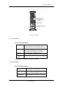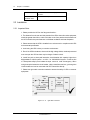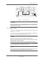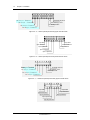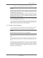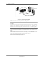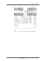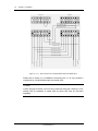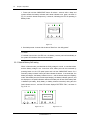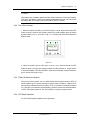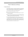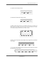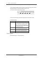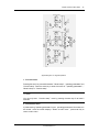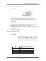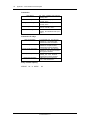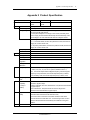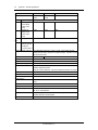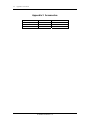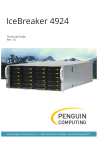
1
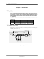
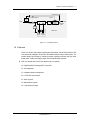
GXT2 - 3X1 Intelligent, High Frequency, Online UPS 10/15/20kVA USER MANUAL E1-20010329-C-1.0 Liebert Corporation IMPORTANT INSTRUCTIONS FOR SAFE USE The UPS must be commissioned by a Liebert - approved engineer before it is put into service. Failure to observe this condition will invalidate any implied warranty . Do not apply power to this equipment before it has been commissioned by a Liebert - approved engineer. He will validate the installation work and install ' site information ' into the micro-controller memory. This information is required to substantiate any warranty claims that might be made. If you find any problems with the procedures in this manual, seek immediate assistance from the Liebert distributor or agent from whom you purchased the equipment. Do not attempt to service this product yourself .It contains no user serviceable parts. All servicing must be referred to qualified personnel. Qualified personnel should be consulted if liquid spills into the product. The UPS is for indoor use only. It must be protected from rain or excessive moisture and installed in clean environment , free from flammable liquids, gasses , or corrosive substances. Do not put drinks, plants, or any other containers holding liquids, on top of the unit. Ventilation grills are provided beneath and at the rear of the cabinet. Do not block or cover these openings otherwise overheating may occur and UPS operation become unreliable. Never poke anything through the ventilation holes or openings. Do not place magnetic storage media on top of the unit as it can corrupt the data stored on them. Electromagnetic Compatibility WARNING This is a Class A UPS product. In a domestic environment this product may cause radio interference, in which case the user may be required to take additional measures. Limits on use: WARNING This UPS should not be supplied from electrical power systems of the 'IT' (Impedance a Terre ) type. (IEC 364-ELECTRICAL INSTALLATION OF BUILDINGS) Content Chapter 1 Introduction 1.1 Application 1.3 System Function Block 1.4 Features Chapter 2 Installation 2.1 Unpacking Inspection 2.2 Outline and Panel Description 2.2.1 Outline 2.2.2 Front Panel 2.2.3 Rear Panel 2.3 Installation 2.3.1 Important Note 2.3.2 Installation Procedure 2.4 Connection of External Batteries Chapter 3 Operation 3.1 Operating Mode 3.1.1 Normal Mode 3.1.2 Bypass Mode 3.1.3 Battery Mode 3.1.4 ECO Mode 3.1.5 Failure Mode 3.2 Operation 3.2.1 Startup and Initialization 3.2.2 Turn On the Inverter 3.2.3 Manual Battery Self-testing 3.2.4 Turn off the Inverter 3.2.5 Totally Shutdown the System 1 1 1 2 5 5 5 5 7 8 8 8 10 13 17 17 17 18 18 19 20 21 21 22 24 25 26 3.2.6 LCD Panel Operation Chapter 4 Maintenance and Storage I. Battery Maintenance II. Keep Air Vent Unblocked III. UPS State Check IV. Function Inspection Chapter 5 Troubleshooting Appendix 1 LCD Panel Displays and Operation 1. Constitution of Display Panel 2. Function of display Panel 3. Menu Operation 4. Information LCD-displaying Priority Relay Communication Mode Appendix 2 Product Specification Appendix 3 Accessories 26 27 27 28 28 28 31 35 35 36 39 42 43 46 49 6 Chapter 1 Product Introduction Chapter 1 Introduction 1.1 Application GXT2-3X1 Series UPS provides high quality AC power to your precision instrument. It can be applied in Computer Center , Network Management Center, Communication System, Automation Control System, precision instrument or other Critical Systems. 1.2 Classification " GXT2-3X1 " Series include 10kVA, 15kVA and 20kVA UPS products, shown in the following table: Capacity 10kVA 15kVA 20kVA Model GXT2-3X1-0100L GXT2-3X1-0150L GXT2-3X1-0200L Description Extended Battery Cabinet is required Extended Battery Cabinet is required Extended Battery Cabinet is required 1.3 System Function Block System can run with as a single UPS, or in Hot-standby mode to increase the system reliability (Refer to figure 1-2). Maintenance bypass Short circuit cable for hot standby Utility bypass bypass breaker Utility Switch Rectifier Inverter Electronic Transfer Switch Load Maintenance switch Charger Battery Group1 Battery Group 2 Figure 1-1 single UPS module E1-20010329-C-1.0 Chapter 1 Product Introduction 7 Maintenance bypass Backup UPS bypass bypass Breaker Utility Rectifier Electronic Transfer Switch Inverter Utility Breaker Load Maintenance switch Charger Master UPS Battery Group1 Battery Group 2 Figure 1-2 hot-standby system 1.4 Features GXT2-3X1 Series Three phase input/Single phase output 10kVA/15kVA /20kVA UPS is an advanced, intelligent, Online with Sinusoidal waveform output UPS system. The system adopts high-frequency double conversion topology structure with high input power factor, wide input voltage range, with the following Key features: UPS can operate with loss of input phases (up to 2 phases) Digital Signal Processing (DSP) Controlled. Self- diagnostic Intelligent battery management LCD & LED annunciation Static by pass Maintenance bypass Large internal charger E1-20010329-C-1.0 Chapter 2 Installation 9 Chapter 2 Installation 2.1 Unpacking Inspection 1. Unpack the packing box to move the UPS to position , be careful not to drop it as it is heavy. 2. In the event of product damage due to transportation, please notify Liebert or its authorized agent. 2.2 Outline and Panel Description 2.2.1 Outline LCD Display Panel Supporting caster Adjustable Footpad Ventilation holes on front panel Figure 2-1 UPS Front view E1-20010329-C-1.0 10 Chapter 2 Installation Air-inlet holes on Front Panel Utility Switch Bypass Switch Maintenance Switch Figure 2-2 Front view without panel Utility Battery Inverter Fault Bypass On/Silence Key LCD Display Off Key Scroll Key Figure 2-3 LCD display Panel E1-20010329-C-1.0 Enter Key Chapter 2 Installation contact closure port Alarm Relay Port Ventilation holes Input/Output Terminals block Figure 2-4 rear panel 2.2.2 Front Panel Parts' Function Description Input Switch Used for controlling the utility input to UPS. 10kVA UPS uses three-pole 63A/250VAC breaker 15/20kVA UPS uses three-pole 100A/250VAC breaker Bypass Switch Used for controlling the bypass input to UPS 10kVA UPS uses 80A/250VAC circuit breaker; 15/20kVA UPS uses 125A/250VAC circuit breaker Maintenance switch For switching UPS to maintenance bypass. Note: To be operated by trained technical Personnel only. Front Panel air inlet hole for ventilation of UPS LCD Panel and Description is in Appendix 1 in detail. 2.2.3 Rear Panel Parts' Function Description Input/output terminals Used for UPS input/output cable connection and external battery connection for UPS Contact closure port Provide Optical Coupler Dry Contact control signal, for OS and UPS shutdown. Alarm relay port bProvide relay Dry Contact alarm/ control signal, E1-20010329-C-1.0 11 12 Chapter 2 Installation It can be included in monitoring system defined by users . Heat Dissipation and ventilation holes Used for heat dissipation and ventilation of UPS 2.3 Installation 2.3.1 Important Note 1. Please position the UPS on the flat ground/surface .. 2. The distance from the rear and side panels of the UPS to the wall or other equipment should be greater than 20cm, and the air inlets on the front panel and at the bottom of the UPS should be kept unobstructed to facilitate ventilation and heat dissipation. 3. Please ensure that the UPS is installed in an environment in compliance with UPS environmental specification. 4. Avoid using the UPS in dusty or corrosive environment. 5. Even if the UPS is shutdown, there could be high voltage inside, untrained personnel must not open the UPS as there may be danger of electric shock. 6. Install four-pole or three-pole interactive circuit breaker with capacity higher than 80A(suitable for 10kVA system)or 125A( for 15kVA/20kVA system)on the hot line of Three-phase utility input to isolate the input source in case of emergency. When using three-pole interactive circuit breaker, utility neutral line need not go through the circuit breaker and can be connected with UPS' neutral line directly. 7. Please use right cable connection method to ensure the safety of UPS or customer equipment:: U V W N Input hot line Input neutral line output hot line U P S output neutral line 4-pole Interactive circuit breaker E Figure 2-5(a) right cable connection E1-20010329-C-1.0 Load Chapter 2 Installation Input hot line U V W Input neutral line 13 output hot line U P S output neutral line Load N/E Figure 2-5 (b) wrong cable connection Warning Classified according to European standard EN55022 , this is an A level UPS product. When it is used in family house, it may generate radio interference, user should take other measures in this condition. 2.3.2 Installation Procedure 1. Prior to any wire connection, please confirm that all the input and output circuit breakers are in “OFF”state; 2. As shown in Figure 2-6, connect the input cables(three hot lines, neutral line and earth line)to the correspondent terminals and secure the screw; Note Please do not reverse connection of the input hot line and neutral line! Because the input default configuration of system's U phase is bypass input, please ensure the proper connection of U phase. Please don't use the power source socket on the wall as the UPS' input source. 3. Connect the input cables (hot lines, neutral line and earth line)of user's equipment to the correspondent UPS output terminals refer , figure 2-6 . Note When connecting the input and output cables, the input hot line and neutral line must be connected correctly and the UPS must be connected to earth firmly. E1-20010329-C-1.0 14 Chapter 2 Installation + - + - L1 B_L Battery 1¡ + °¡ ± Terminal Battery1 + Terminal Battery 1¡- °-Terminal ¡ ± Terminal Battrery1 B_N Hot standby B_N End Hot standby B_L End Hot standby L1 End Battery 2¡ °+¡ ± Terminal Battery2 + Terminal Battery 2¡ -°¡ T ±erminal Battery2 - Terminal Figure 2-6(a) 10kVA Input/output terminals( upper terminals' block) N U L W V N Input GND Output GND Output Neutral line Input Neutral line Input U phase line Output phase line Input V phase line Input W phase line Figure 2-6(b)10kVA Input/output terminals (lower terminals' block) + - + - B_N B_L L1 Battery 1¡ + °¡ T ±erminal Battery1 + Terminal Battery1 Terminal Battery 1¡ -°¡ ± Terminal Hot standby B_N End Hot standby B_L End Hot standby L1 End Battery 2¡ °+¡ T ±erminal Battery2 + Terminal Battery 2¡ °-¡ T ±erminal Battery2 - Terminal Figure 2-6(c) 15/20kVA Input/output terminals (upper terminals' block) N U V W Input GND Input Neutral line Input U phase line Input V phase line Input W phase line E1-20010329-C-1.0 L N Output GND Output Neutral line Output phase line Chapter 2 Installation 15 Figure 2-6(d) 15/20kVA Input/output terminals( lower terminals' block) Note For 10kVA system, at least 8AWG or 10mm2 copper wire should be used for input neutral line, input U phase line, hot standby L1 terminal, B_L terminal, B_N terminal and output neutral line and hot line;input V or W phase lines and battery lines should be 10AWG or 6mm2 copper wire at least. For 15/20kVA system, at least 3AWG or 25mm2 copper wire should be used for input neutral line, input U phase line, hot standby L1 terminal, B_L terminal, B_N terminal and output neutral line and hot line;input V or W phase lines and battery lines should be 5AWG or 16mm2 copper wire at least. 4. For external battery connection, please refer to the procedures of external battery cables connection (please refer to figure 2-4); 5. To connect the UPS to servers for OS shutdown, please connect server's serial port to the contact closure port at the rear of the UPS. Follow installation procedure of OS shutdown software ( Liebert's multiLink ) for proper installation. 2.4 Connection of External Batteries 1. The system needs to be connected with two strings of 240V batteries, the switch on the battery cabinet must be in "OFF" position, prior to connecting the batteries. Note Batteries of different models and make can not be used together. 2. Confirm that the batteries quantity conforms the UPS' specification, voltage of each group of batteries should be 240 Vdc nominal or around 250 Vdc measured with a volt meter. 3. Use a voltage meter to confirm that the voltage across the battery terminals on the UPS Input/output terminals' block is zero, before connecting the battery cable to the UPS. 4. According to the wire connection shown in Figure 2-10, connect the positive pole( red ) and negative pole( black ) to the "+" and "-" battery terminals on terminals' block respectively and secure the terminals, pay attention not to reverse the batteries connection . For 15/20kVA UPS, it is necessary to use Ferrite T-core in the accessories as shown in Figure 2-10; E1-20010329-C-1.0 16 Chapter 2 Installation Battery Cabinet Breaker of Battery Cabinet Battery 2 Battery 1 + _ + _ Figure 2-10 connection of external batteries 5. Turn the switch on the battery cabinet to " ON " position. Note The battery connection and replacement should be done when the UPS is Completely switched OFF, if batteries are replaced while UPS is ON (hot - swappable ) pay attention not to reverse battery polarity. 2.5 Wire Connection for Hot Standby UPS 1. Confirm the input circuit breakers of the master UPS and slave UPS are in "OFF " state ; 2. Remove the short circuit cable used for hot standby of the master UPS(the short circuit cable between hot standby L1 terminal and B_L terminal); 3. Connect the wires according to Figure 2-11. E1-20010329-C-1.0 Chapter 2 Installation Backup UPS + - L1 B_L B_N + - + - L1 B_L L N Output phase line - Output Neutral line + Master UPS B_N Output neutral line of Backup UPS is connected to the N terminal of Master's bypass Output phase line of Backup UPS is connected to the L terminal of Master's bypass N U V W L N N U V W Output GND in Parallel Input GND in Parallel Input Neutral line in Parallel Input U phese line in Parallel Input V phase line in Parallel Input W phase line in parallel E1-20010329-C-1.0 Output GND Input W phase line Input V phase line Input Neutral line Input V phase line Input GND Figure 2-11(a) Wire connection for 10kVA Master-slave hot standby UPS 17 18 Chapter 2 Installation Backup UPS + - + - Master UPS L1 B_L B_N + - + - L1 B_L B_N Output neutral line of Backup UPS is connected to the N terminal of Master's bypass Output phase line of Backup UPS is connected to the L terminal of Master's bypass V W L N N U V W L N Output Neutral line U Output phase line N Output GND in Parallel Input GND in Parallel Input Neutral line in Parallel Input U phese line in Parallel Input V phase line in Parallel Input W phase line in parallel Output GND Input W phase line Input V phase line Input V phase line Input Neutral line Input GND Figure 2-11(b) Wire connection for 15/20kVA Master-slave hot standby UPS Please refer to section 2.3.2 Installation Procedures( item 3 ) for wire connection requirement for 15/20kVA Master-slave hot standby UPS. Note Confirm the right connection of hot line and neutral line and proper earthing. For hot standby UPS, the batteries of master UPS and slave UPS must be connected separately. E1-20010329-C-1.0 Chapter 3 Operation 19 Chapter 3 Operation 3.1 Operating Mode 3.1.1 Normal Mode When the input Utility voltage and the load are within specifications, the load is supplied by inverter, which draws power from rectifier; meanwhile, the charger float-charges or equalize-charges the battery. When in Normal mode, the Utility indicator and inverter indicator on the LCD panel be green in colour ,as shown in Fig. 3-1. OUTPUT VOLT 220.0V Figure 3-1 Note If the UPS is power by generator set , please follow the requirements below: 1. Start up the generator set first without switching on the loads, connect the UPS to the generator, then switch on the loads one by one till the generator operates stably (to ensure reliable operation of the generator, it is recommended that the UPS load be less than 30% of generator capacity). 2. It is recommended that the generator capacity be 1.5~2 times of UPS rated capacity. 3.1.2 Bypass Mode When utility is present and UPS is not turned on , or in the event of overload or other faults after the UPS is turned on, the load is supplied by Bypass AC source, which feeds directly from the Utility input; and meanwhile the charger will charge the battery. When in Bypass mode, the bypass indicator on the LCD panel turns green, as shown in Fig. 3-2. Please note: In the event of bypass power failure or bypass voltage falling outside tolerance when the UPS is in Bypass mode, the UPS will cease to supply electricity to the load . E1-20010329-C-1.0 20 Chapter 3 Operation OUTPUT VOLT 215.0V Figure 3-2 Note Under this mode, if the bypass power fails or bypass voltage exceed the bypass voltage windows. , the UPS will not provide power to the load. 3.1.3 Battery Mode When the UPS is in Normal mode, in the event of Utility failure or Utility voltage outside tolerances, the rectifier and charger will turn off , the battery begins to discharge and supply the load through inverter. When the UPS operates in Battery mode, the battery indicator and inverter indicator on the LCD panel turns green, as shown in Fig. 3-3, accompanied with a beep every 3 seconds, giving alarm that the UPS is operating in Battery mode. OUTPUT VOLT 220.0V Figure 3-3 In Battery mode, when the battery voltage is low the preset level , there will be a beep every 1 second, and the LCD screen displays "BATTERY LOW SHUTDOWN IMMINENT " . Note: E1-20010329-C-1.0 Chapter 3 Operation 21 Although the battery had been fully charged at factory before delivery, the transport and storage may result in loss of capacity , hence charging the battery for 8 hours is required before installing the UPS , so as to ensure adequate battery backup time. 3.1.4 ECO Mode ECO mode is the economic operation mode. For the load equipment which is less critical , users can select ECO mode to power the equipment to reduce the power consuming. When the bypass voltage is normal, the bypass powers the load and the inverter supplies no load, bypass indicator on the Control Panel is on(green), as shown in Figure 3-4. OUTPUT VOLT 215.0V Figure 3-4 Note Under ECO mode, if bypass power falls out of the bypass voltage range and there is no overload , the UPS will switch into inverter mode; however if there is an overload and bypass power fails or the bypass voltage is beyond the range the UPS will not go into inverter working mode and bypass will be shut off , load will be disrupted. . 3.1.5 Failure Mode In the event of inverter fault, internal overtemperature or other faults in Normal mode, the UPS transfers to Bypass mode; however if this occurs in Battery mode, the UPS shuts down. In the event of UPS fault, the fault indicator on the LCD panel turns red, as shown in Fig. 3-4. Meanwhile, the buzzer beeps (except battery and charger fault), and the LCD screen displays corresponding fault information, see Appendix 1. E1-20010329-C-1.0 22 Chapter 3 Operation OUTPUT VOLT 215.0V Figure 3-5 3.2 Operation 3.2.1 Startup and Initialization After checking and making sure that the input and output cables are connected correctly, turn on the Utility switch and the bypass switch (for long backup time UPS, turn on the battery switch before closing the Utility switch). Then the system starts up, the internal fan begins to run, and the system begins to conduct self-test. After system self-test (the buzzer beeps twice indicating normal startup), the system enters in Bypass mode, the Utility indicator and bypass indicator turns green, as shown in 3-6. OUTPUT VOLT 215.0V Figure 3-6 3.2.2 Turn On the Inverter 1. Start in Normal Mode 1, After system power-on, press and hold the ON/SILENCE button for 1 second, then a beep is heard. Several seconds later, the bypass indicator goes off and the inverter indicator turns ON as shown in Fig. 3-7, the UPS is then operating in Normal mode. E1-20010329-C-1.0 Chapter 3 Operation 23 OUTPUT VOLT 220.0V Figure 3-7 Note If the previous shutdown was resulted from termination of battery discharge because of Utility failure, the automatic function will be activated when the Utility restores. 2, After the system is started up properly , apply the load gradually and monitor the load condition through LCD, as shown in Figure 3-8: LOAD 70.0% Figure 3-8 3, In the event of load exceeding the rated capacity of the UPS, of 105% load , the buzzer will beep every 0.5 second with corresponding load percentage indication . Remove load accordingly so the UPS is not operating under overload condition. Note If the system transfers from Normal mode to Bypass mode for 3 times within 1 hour due to overload, it will remain in Bypass mode for 1 hour and can't transfer back to Normal mode till the overload is removed. 2. Start in Battery Mode E1-20010329-C-1.0 24 Chapter 3 Operation 1. Press and hold the ON/SILENCE button for about 1 second, after a beep and system self-test, the battery indicator and inverter indicator turns green, as shown in Fig. 3-9, and the buzzer beeps every 3 seconds, indicating the UPS is operating in Battery mode. OUTPUT VOLT 220.0V Figure 3-9 2. Overload process is same with the above "Start from the utility power". Note If overload occurs when the UPS is on the battery, remove part load immediately or the system will shutdown after a short time lapse. 3.2.3 Manual Battery Self-testing When in Normal mode, provided that the Utility voltage is normal, no overload exists, and the battery voltage is not lower than 240V, battery test can be conducted by pressing button on the LCD panel press and hold the ON/SILENCE button for 4 seconds (a beep is heard 3 times) and then release the button . 3 seconds later, the battery test begins, the battery indicator turns on , and the buzzer beeps as in Battery mode. After battery test, the buzzer stops beeping, the battery indicator goes off, and the displays on the panel indicators restore to the state prior to test. When battery fault is detected (no battery, faulty battery, or battery reverse connection) during test, the fault indicator turns on , and the LCD screen displays "BATTERY FAIL", as shown in Fig. 3-10(b). OUTPUT VOLT 220.0V Battery Fault Figure 3-10(a) E1-20010329-C-1.0 Figure 3-10(b) Chapter 3 Operation 25 Note After battery test, the battery state information will be refreshed. In the event of battery fault due to the battery not bang fully charged is detected during test, user may re-test the battery after fully charging it to confirm that the fault is removed. 3.2.4 Turn off the Inverter 1. When the system has Utility input and the Utility is normal, press and hold the OFF button for about 1 second, then a beep is heard, the inverter indicator goes off and the bypass indicator turn on , as shown in Fig. 3-11, indicating the UPS has transferred to Bypass mode. OUTPUT VOLT 215.0V Figure 3-11 2, When the system has no Utility input (in Battery mode), press and hold the OFF button for about 1 second, then a beep is heard, the UPS will have no output and the LCD screen displays "UPS SHUTDOWN". About 30 seconds later, all panel indicators go off, and the fan stops running. 3.2.5 Totally Shutdown the System After turning off the inverter, turn the Utility switch and the bypass switch to OFF, all panel indicators go off, and the fan stops running (if there is a battery, a delay time of 30 seconds is needed before the fan stops). Then , the system is completely powered off. If the UPS is connected to external battery, place the switch of the external battery to OFF. After system power-off, the UPS will have no output to supply the load. 3.2.6 LCD Panel Operation For LCD Panel Operation please refer to Appendix 1. E1-20010329-C-1.0 Chapter 4 Maintenance and Storage 27 Chapter 4 Maintenance and Storage I. Battery Maintenance The internal battery of GXT2-3X1 series UPS is sealed, lead-acid, maintenance-free battery. The battery life depends on the ambient temperature, charge and discharge cycles . High ambient temperature and deep discharge can shorten battery life. To ensure battery life, the battery should be maintained regularly: Keep the ambient temperature between 15℃ and 25℃. Prevent small current discharge, continuous battery discharge time exceeding 24 hours is must be avoided . When the UPS hasn't been used for a long time, and the battery hasn't been charged for 3 months at specified ambient temperature, or 2 months at high ambient temperature, please charge it for at least 12 hours. As to external battery of long backup time UPS, the wiring terminals of the external battery must be checked regularly and, when necessary, should be cleaned. If the battery backup time is found noticeably shortened, or when the UPS LCD displays "BATTERY FAIL", please contact the Liebert or its authoriged agent to confirm whether the battery needs to be replaced. Before replacement, please make sure that the specifications of the new batteries are correct. E1-20010329-C-1.0 28 Chapter 4 Maintenance and Storage Notice 1. Never short-circuit the battery terminals, which may result in fire. 2. Never open the battery, as the electrolyte is harmful to human body. In the event of inadvertent contact of electrolyte, immediately rinse it off with water and go to hospital for treatment . II. Keep Air Vent Unblocked 1. Regularly clean the system, especially the air inlet and air outlet. Make sure the air flows freely inside the chassis. Use vacuum cleaner for cleaning when necessary. 2. Check the air vents on the front, rear, and side panels, make sure they are not obstructed . III. UPS State Check 1. Check whether the UPS is faulty: is the fault indicator ON ? Is fault alarm being displayed. 2. Is the UPS operating in Bypass mode: in normal case, the UPS operates in Normal mode; if it is operating in Bypass mode, please find out the reason, for instance: operator intervention, overload, internal fault, etc. 3. Is the battery discharging: when the Utility is normal, the battery shouldn't discharge; if the UPS is operating in Battery mode, please find out the reason, for instance: Utility failure, battery test, operator intervention, etc. IV. Function Inspection It is recommended to inspect the UPS functions once half year. 1. Press the OFF button, check whether the buzzer, LED indications and LCD display are normal (see Section 3.1 Operation Mode). Please do this after confirming that the Utility is normal and data backup has been done. 2. Press the ON/SILENCE button, check again whether the LED indications and LCD display are normal and the UPS transfers to Normal mode. 3. When the inverter is in Normal mode (the inverter indicator is on ), press and hold the ON/SILENCE button for 4 seconds to start battery test. Should any battery problem be found, immediately find out the problem and solve it. E1-20010329-C-1.0 Chapter 5 Handling Abnormal Problem 29 Chapter 5 Troubleshooting In the event of UPS fault, please check and remove the fault immediately following the methods described in the table below. If the fault persist , please contact Liebert or its authoriged agents. Sequence No. Phenomena Description 1 No panel display and system self-test when the Utility switch is in the ON position. A. Utility hasn't been introduced into the system; B. Input undervoltage. Use voltmeter to check whether the input Utility voltage is within tolerances. 2 The Utility is normal, but the Utility indicator does not turn to and the UPS operates in Battery mode. A. The input switch is turned off; B. The input power line is not properly connected; A. Turn on the input switch; B. Make sure that the input power line is properly connected; 3 No alarm is given, but there is no voltage output. The output power line is Make sure that the output not properly connected. power line is properly connected. 4 No panel display and system self-test when the Utility switch is in the ON position. A. Utility hasn't been introduced into the system; B. Input undervoltage. Use voltmeter to check whether the input Utility voltage is within tolerances. 5 The Utility indicator flashes. The Utility voltage is outside tolerances. If the UPS is operating in Battery mode, please note the battery backup time. The buzzer beeps Overload. Disconnect some loads from the UPS. 6 Cause every 0.5 second, and Action the LCD displays "OVERLOAD" 7 The fault indicator is on A. The external battery A. Check whether the and the LCD displays switch is turned off, or external battery switch is turned on and its lead is "BATTERY FAIL". its lead is not properly properly connected; connected; B. Check whether the B. Battery reverse battery is reversely connected; connection; C. Contact the distributor C. Battery damaged; for battery replacement; 8 The fault indicator is on , and the LCD displays "CHARGER FAIL". Charger fault E1-20010329-C-1.0 Contact the Liebert or its authoriged agent for charger replacement/maintenanc e. 30 Chapter 5 Handling Abnormal Problem Sequence No. Phenomena Description Cause Action 9 The UPS has reduced A. The battery is not battery time. fully charged; B. The battery is not able to hold a full charge due to age. A. Allow the battery to charge for more than 8 hours when the Utility is normal, and then re-test the discharge time; B. The battery needs replacement, please contact the Liebert or its authoriged agent. . 10 The buzzer beeps, the Internal fault indicator shines, overtemperature and the LCD displays "TEMP OVER" A. Check whether there is air flowing out from inside. B. Remove the objects blocking the vent, or widen the distance from the wall; C. Wait for 10 minutes for the UPS cools down, then restart it. 11 The buzzer beeps, the UPS output short-circuit. fault indicator is on , and the LCD displays "OUTPUT SHORT" Restart the UPS after confirming that load short-circuit does not exist. 12 The buzzer beeps, the UPS internal fault fault indicator shines, and the LCD displays "RECTIFIER FAIL", "INVERTER FAIL", "AUX SUPPLY FAIL", or "OUTPUT FAIL". The UPS needs maintenance, please contact the Liebert or its authoriged agent immediately . 13 Abnormal noise or smell inside the UPS. Turn off the UPS and cut off the power input immediately, contact Liebert or its anthoriged agent for assistance. UPS internal fault When reporting UPS , please provide the machine model and machine serial No. (the bar code on the rear panel of the UPS). E1-20010329-C-1.0 Chapter 6 Service after Sales 31 Appendix 1 LCD Panel Displays and Operation LCD display interface is formed by LCD, LED and keys (see Appendix-Figure 1-1), it mainly finish the displaying and control of the following information: UPS basic parameter information, operating parameters information, alarm information, failure code information and function setup information. Utility indicator (green) Battery indicator (green) Inverter indicator (green) Fault indicator (red) Bypass indicator (green Silence Key LCD Display Panel Off Key Scroll Key Enter Key Appendix-Figure 1-1 LCD Panel 1. Constitution of Display Panel The Panel is formed by 1 group LED indicator, 1 LCD screer and 4 keys. 1) LED indicators are formed by 4 green lights and 1 red light. 2) LCD can display double-row Chinese information or 4-row English information. 3) The keys are :On/Silence key, Off key, scroll key and Enter key. 2. Function of display Panel 1. Displaying information of LED 1)failure indicator(red): on only when failure is detected .2)The Utility indicator (green): when the Utility is normal, it is on, when utility fails the indicator is off, when utility is out of range , it flashes. 3)Inverter indicator(green):when the inverter is working, it is on;when it does not work, the indicator is off. 4)Bypass indicator(green):when the Bypass is working, it is on; when it is not activated , the indicator is off. E1-20010329-C-1.0 32 Chapter 1 Product Introduction 5)Battery indicator(green):when the battery is discharging , it is on; when it not discharging , the indicator is off. 2. Display Information 1)UPS basic parameter information Displays UPS' Model and present on/off state 2)operating parameters information OUTPUT VOLT, OUTPUT FREQ, OUTPUT CURRENT, LOAD, INPUT VOLTAGE(U), INPUT VOLTAGE(V), INPUT VOLTAGE(W), INPUT FREQ, BYPASS VOLT, BATTERY VOLTAGE 1/CHARGING VOLT1, BATTERY VOLTAGE 2/CHARGING VOLT 2, BATT CAPACITY CHARGING/FULL CHARGED, INTERNAL TEMPERATURE. 3)alarm information(According to priority, from the highest to the lowest) UPS SHUTDOWN, AUX SUPPLY failure, OUTPUT SHORT CIRCUIT, INVERTER FAIL, RECTIFIER FAIL, OVER TEMP, OVERLOAD, CHARGER FAIL, BATTERY FAIL, NEUTRAL FAIL, I/P PHASE FAIL, BATTERY LOW shutdown imminent and output SWITCH FAIL. 4)failure information Displays the recorded failure code before the last UPS shutdown at power off. 5)Configuration Settings Chinese/English menu setup, OPERATING MODE setup, BOOST CHG SET, TEMP COMP SET, BATT CAP SET, M/S setup M/S cycle time set up , equipment address setup, frequency tracking range setup. (1) Chinese/English menu settings includes: Chinese English No change (2) working mode settings includes: Normal Mode E1-20010230-C-1.0 ECO Mode No change Chapter 6 Service after Sales 33 (3) equalize function settings includes: Enable Disablet No change (4) temperature Compensation settings includes: Enable Disable No change (5) Battery Capacity setup means the Ah of batteries used by UPS, for example: The battery capacity in two battery groups( each group contains 20 batteries) is all 100Ah, so the battery Capacity should be set up as 100Ah, includes: 24Ah 28Ah 38Ah 52Ah 65Ah 76Ah No change 84Ah 500Ah 400Ah 300Ah 200Ah 130Ah 100Ah (6) Master, Slave, Single setup includes: Master, Slave, Single UPS, No modification of the settings. Master Slave Single Ups No change (7) The master-slave alternated time can only be set up for the master so as to decide the alternated time with the slave. 7 days 30 days 90 days E1-20010329-C-1.0 180 days No shift No change 34 Chapter 1 Product Introduction (8) The equipment address setup can directly change the 3-bit digit which forms the equipment's address, the equipment address range is 0~255. (9) Frequency tracking range settings includes: 1% 2% 4% 6% 10% No change User can select according to the power supply frequency requirement of load. 3. Function of Keys Key Function 〈On/Silence〉 When the UPS is in off state, pressing this key for 1 second switch on the inverter ; When the UPS is in alarm mode , pressing this key for 1 second can silence the alarm ; When the UPS is on with no alarm, pressing this key for 4 second can start battery self testing. 〈Off〉 When the UPS is on with no alarm, pressing this key for 1 second will shutdown the inverter. 〈Scroll 〉 Scroll between different menus of the same level or complete the parameter selection . 〈Enter〉 Used in opening the menu, confirm and return. 3. Menu Operation See Appendix-Figure 1-2: Keypad Operation: E1-20010230-C-1.0 Chapter 6 Service after Sales 35 Enter Enter scroll scroll Prohibit scroll cycle ( Display Present Value ) EC setup Enable Back to Main Menu Run Para Enter scroll ... scroll Present Second Alarm scroll Enter Enter ... scroll Temp Compensate setup scroll Enter scroll ( Display Present Value ) No change scroll Maintain 5S Basic Infor scroll Fuction Setup Alarm Infor Enter scroll Back to Main Menu Run Para Enter Output Volt scroll Fault record scroll Run Para scroll scroll Enter Output Freq Enter Operating Parameters scroll ... scroll Back to Main Menu Present Second Alarm Appendix-Figure 1-2 Keypad Operation 1. first level menu Pressing the scroll key can switch between " failure lookup", " operating parameters" and "function setup". Press the enter key to enter the menus of " operating parameters" ," failure lookup" or " function setup ". Note You can only enter “function setup”menu by pressing the enter key for at least 5 seconds 2. second level menu A) After entering "operating parameters" menu , operating parameters' information can be viewed ; when the screen displays " Return to main menu" , press enter key to return to main menu. E1-20010329-C-1.0 36 Chapter 1 Product Introduction B) After entering " function setup " menu , function information which can be setup can be viewed and set by pressing the scroll key ; when the screen displays " Return to main menu", press enter key to return the main menu of " operating parameters ". C) After entering " function setup" menu , the parameters whose value is to be modified are displayed in reverse contrast text mode and the parameters' values can be changed by pressing the scroll key ; save the parameters which have already been modified by pressing the enter key and the parameters' value will be stored and the value display will switch from reverse contrast to normal text mode. Note When the equipment's address is changed, the charging between 3-bit digits are done through auto shifting when no key is pressed for 3 seconds. D) When it is in alarm state, alarm information can be viewed by pressing the scroll key;When the screen displays "Return to main menu" , press the enter key to return "operating parameters" main menu. 4. Information LCD-displaying Priority 1. LCD will display present alarm information of the highest priority if no key is pressed in 30 second. 2. LCD-displaying information will not be changed when there is no alarm, the LCD will display level 2 sub menu such as "Output current" when no key is pressed. On the contrary, if the LCD isn't displaying the level 2 sub menu information and no key is pressed in 30 second, it will return to the state to display " Output voltage: xxx ". E1-20010230-C-1.0 Appendix 2 Communication Port Description 37 Dry Contact Communication Mode Port Definition NC Utility Fail NC GND Battery Undervolt 1 2 3 4 5 6 7 8 9 OFF GND NC NC Pin2 : When the Utility fails, this pin will change from OPEN to CLOSE, it is OPEN in normal state; Pin5 : When the battery voltage is low, this pin will change from OPEN to CLOSE, it is OPEN in normal state; Pin6 : When +5V voltage has been applied for 1 second, the UPS will shutdown; Pin4 : GND for signal; Pin7 : GND for signal; Other Pin: No wire connection Dry Contact Communication Mode can perform the following functions When the Utility fails, the Utility failure information is provided ; When the battery capacity is going to be used up, battery low information will be provided ; Control the shutdown of UPS. Relay Communication Mode Port Definition 1 2 3 ALARM 4 5 6 7 8 9 FAULT BYPASS 10 11 12 BATT ¡ L ¤OW Signal alarm failure Bypass Output signal , summary alarm , non shutdown alarms only. Output signal UPS fail , will shutdown or transfer to bypass. Output signal, power supplying mode battery low Output signal, battery mode shutdown input signal, UPS shutdown command E1-20010329-C-1.0 13 14 15 SHUTDOWN 38 Appendix 2 Communication Port Description Connection alarm Signal failure Signal Bypass mode signal battery low Signal Shutdown Signal Pin . 1/2/3 (normally open /common normally close) Pin . 4/5/6 (normally open/common /normally close) Pin . 7/8/9 (normally open/common /normally close) Pin . 10/11/12 (normally open/ common / normally close) Pin .14/15th Pin(short circuited normally , UPS shutdown when open circuit ) Connection of relays alarm Signal Relay failure Signal Relay Bypass mode Signal Relay battery low Signal Relay Shutdown Signal Relay In normal state, Pin . 2/3 are short circuited, Pin . 1/2 pins are short circuited when alarm is activated . In normal state, Pin . 5/6 are short circuited, No. 4/5 pins are short circuited when signal is activated. In normal state, Pin . 8/9 are short circuited, Pin .7/8 are short circuited when signal is activated. In normal state, Pin . 11/12 are short circuited_, Pin . 10/11 are short circuited when signal is activated . Invalid when pin 14/15 are open circuit , UPS will shutdown . Relay Contact Capacity 250VAC 2A or 30VDC 2A E1-20010329-C-1.0 Appendix 3 Product Specification Appendix 2 Product Specification Capacity 10kVA 15kVA 20kVA Model GXT2-3X1 -0100L GXT2-3X1 -0150L GXT2-3X1 -0200L Input Input Mode Three-phase/four-line input rated voltage 400 Vac( line to line) voltage range 1. If the Phase to neutral voltage is in the range of 176-276Vac, the UPS can work normally with full load; 2. If the phase voltage is in the range of 120-176Vac, the ability of the UPS to supply the load will decrease linearly with the decreasing of the input voltage, it can work with half load when the voltage is 120Vac. 3. Working under Phase failure condition: 1)if one Phase failure, the other two phases are normal, the UPS can supply 50 % rated load at most; 2)if input two phases failure, the other one phase is normal, the UPS can supply 25 % rated load at most Frequency Power Factor Output Output Power Factor 45~55Hz ≥0.95 At rated load and rated voltage 0.7 Voltage 230Vac±3% Line regulation < ± 1% (0~100% Linear Load) Load e regulation < ± 2% (0~100% Linear Load) Voltage Distortion < 4%(0-100% Linear Load);< 5%(0-100% nonlinear Load) Frequency In normal mode, when the Bypass frequency is in the tracking range (50Hz±10%, 6%, 4%, 2% and 1% optional, defailure value is ± 4%),the inverter Output will track Bypass frequency;when the Bypass frequency is beyond the limit, the inverter Output frequency is 50Hz± 0.2%;in battery mode, the inverter Output frequency is 50Hz±0.2% Frequency slew rate 1 Hz/s Inverter Overload be able to withstand 105~125% rated load for 10min;then the UPS transfers to bypass output; Capability be able to withstand 125~150% rated load for 1min,then the UPS transfers (Utility or to bypass output; Battery) When Load Power> 150%,the inverter can work for longer than 200ms,then the UPS transfers to bypass output; Bypass Overload Ability If the load current is in the range of 135%-155% rated output current,the UPS will be disconnected from the load after 15min; If the load current is more than 155% rated current,the UPS will be disconnected from the load after 3min(if extreme big current occurs in 3min,the disconnection time is decided by the release time of bypass breaker) Crest Factor 3:1 E1-20010329-C-1.0 39 40 Appendix 3 Product Specification Capacity 10kVA 15kVA 20kVA Model GXT2-3X1 -0100L GXT2-3X1 -0150L GXT2-3X1 -0200L Bypass Voltage 120~253Vac (non- ECO mode) Efficiency in Normal Mode (100% Linear Load) > 89% > 89% > 89% Efficiency in battery mode (100% Linear Load) > 88% > 88% > 88% interrupt Utility Failure time 0ms < 4ms Transferring between inverter and Bypass (Synchronized ) Voltage transient response At the Resistive Load from 0~100% or 100%~0, the Output dynamic voltage change range is lower than 5% Rated Voltage. Transient recovery time is less than 60ms. Audible Noise < 55dB(1m) Display LCD Safety Passed CCEE certification,complied with EN60950 and EN50091-1. < 60dB(2m) Highest Input Voltage : Line Voltage 554Vac,1 hour(static) EMC Conduction:EN55022 Class A Radiation: EN55022 Class A Immunity EN61000-4-2.3.4.5.6.8.11 Level III DC offset Lower than ±500mVdc MTBF(Inverter ) 30000 hours (ambient temperature is 25℃,rated condition) MTBF(System) 150000 hours (Response time + maintenance time should be less than 24 Harmonic current:THD<25%(With input isolated transformer connected) hours) MTTR (Board Maintenance) 1 hour(Board Maintenance) Insulation Resistance dielectric Strength > 2MW (500Vdc) ( Output to earth,Input to earth )2820Vdc,leakage current<3.5mA, 1min with no arc and breakdown Surge Protection Satisfy the IV type of IEC60664-1, that is the ability to withstand 1.2/50uS+8/20uS exceeds 6kV/3kA. Protection Level IP21 E1-20010329-C-1.0 Appendix 3 Product Specification Capacity 10kVA 15kVA 20kVA Model GXT2-3X1 -0100L GXT2-3X1 -0150L GXT2-3X1 -0200L Environment Condition E1-20010329-C-1.0 41 42 Appendix 4 Accessories Appendix 3 Accessories Optional Product name battery cabinet Product Model Remark UF-B0100-38 20 38Ah batteries UF-B0100-65 20 65Ah batteries UF-B0100-100 20 100Ah batteries E1-669001-20010230-C-1.0