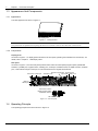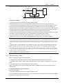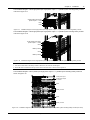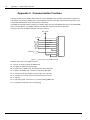
1
iTrust Adapt 10kVA UPS User Manual Version V1.0 Revision date [输入归档月日年] BOM 31012216 Emerson Network Power provides customers with technical support. Users may contact the nearest Emerson local sales office or service center. Copyright © 2009 by Emerson Network Power Co., Ltd. All rights reserved. The contents in this document are subject to change without notice. Emerson Network Power Co., Ltd. Address: No.1 Kefa Rd., Science & Industry Park, Nanshan District 518057, Shenzhen China Homepage: www.emersonnetworkpower.com.cn E-mail: [email protected] Safety Guidelines Prohibitions 1. Non-professionals are prohibited to install or commission the UPS alone. 2. As hazardous voltages are present within the UPS, only an Emerson technician or an Emerson-authorized technician is permitted to open it. Failure to observe this could result in electric shock risk and invalidation of any implied warranty. 3. Never dispose of the battery in a fire, as it may explode and jeopardize personnel safety when exposed to flame. Matters needing attention 1. The standard UPS has its own energy source, external battery, therefore, the output terminal of the UPS may carry live voltage even when the UPS is not connected to the AC mains. 2. Before moving or re-wiring the UPS, please disconnect the mains source and make sure the UPS is completely shut down. Or else, the output terminal may carry live voltage, thus presenting electric shock risk. 3. To ensure human safety and normal operation, the UPS must be solidly and adequately grounded before use. 4. The operating environment and save method affect the UPS lifetime and reliability. It is advisable not to use the UPS for long in the following environments: Places where the temperature and relative humidity are outside the specifications (temperature: 0°C ~ 40°C, relative humidity: 5% ~ 95%) Places in direct sunlight or near heat source Places subject to vibrations or shocks Places which are dusty, strewn with corrosive substances or salts, or where flammable gases are present 5. Please keep the air inlet and outlet unobstructed. Poor ventilation will increase the internal temperature, which will shorten the lifetime of the UPS components, hence that of the UPS. 6. Liquid and other irrelevant objects are strictly prohibited inside the UPS. 7. In case of fire, use dry chemical fire extinguisher to put out the fire. Using foam fire extinguisher may cause electric shock. 8. High ambient temperature shortens the battery lifetime. To ensure normal UPS operation and adequate autonomy time, the battery should be replaced periodically. Only Emerson-authorized technicians are permitted to replace the battery. 9. If the UPS will remain idle for a long period, it must be stored in a dry environment. The storage temperature should range between -20°C and +55°C for standard UPS (with internal battery), between -40°C and +70°C for extended UPS (with no internal battery.) 10. This UPS complies with IEC61000-3-12 provided that the short-circuit ratio Rsce is greater than or equal to 250 at the interface point between the user’s supply and the public system. It is the responsibility of the user to ensure, by consultation with the distribution network operator if necessary, that the equipment is connected only to a supply with a short-circuit ratio Rsce greater than or equal to 250. 11. The UPS output cable must be less than 10m. 12. The backfeed protection unit is external. Refer to UF-BFP-63A Backfeed Protection Unit User Manual for its using method. Others When the UPS is purchased to deliver power to the equipment listed below, please discuss with the distributor in advance about the applicability, settings, management and maintenance of the UPS, as these need special considerations during design and development. Life-supporting medical apparatus Facilities such as lifts/elevators where adequate care has to be taken to avoid any fatal eventuality endangering human life Any other mission-critical equipment like the above Contents Chapter 1 Product Description ............................................................................................................................................ 1 1.1 Features ................................................................................................................................................................ 1 1.2 Model Configuration .............................................................................................................................................. 1 1.3 Appearance And Components .............................................................................................................................. 2 1.3.1 Appearance ............................................................................................................................................... 2 1.3.2 Components .............................................................................................................................................. 2 1.4 Operating Principle ............................................................................................................................................... 2 1.5 UPS State And Operation Mode ........................................................................................................................... 3 1.5.1 Normal Mode ............................................................................................................................................. 3 1.5.2 Bypass Mode ............................................................................................................................................. 3 1.5.3 Battery Mode ............................................................................................................................................. 3 1.5.4 ECO Mode ................................................................................................................................................. 4 1.5.5 Fault State ................................................................................................................................................. 4 1.6 Specifications ........................................................................................................................................................ 4 Chapter 2 Installation .......................................................................................................................................................... 6 2.1 Unpacking Inspection............................................................................................................................................ 6 2.2 Installation Preliminaries ....................................................................................................................................... 6 2.3 Mechanical Installation.......................................................................................................................................... 6 2.3.1 Installing UPS ............................................................................................................................................ 7 2.3.2 Installing Plastic Panel ............................................................................................................................... 8 2.3.3 Operating Display Panel ............................................................................................................................ 9 2.4 Cable Connection ............................................................................................................................................... 10 2.4.1 I/O Terminal Block ................................................................................................................................... 10 2.4.2 Connecting Input And Output Cables ...................................................................................................... 10 2.4.3 Connecting Battery Cables ...................................................................................................................... 11 2.4.4 Connecting Communication Cables ........................................................................................................ 12 2.4.5 Connecting REPO Cable ......................................................................................................................... 13 2.4.6 Connecting 10A External Charger Cable ................................................................................................. 13 2.5 1 + 1 Parallel System (Optional) ......................................................................................................................... 14 2.5.2 Mechanical Installation ............................................................................................................................ 14 2.5.3 Setting Parallel Addresses....................................................................................................................... 16 2.5.4 Connecting Parallel Cables ..................................................................................................................... 16 2.5.5 Connecting POD Cables.......................................................................................................................... 17 Chapter 3 LED Display Panel............................................................................................................................................ 19 3.2 Control Keys ....................................................................................................................................................... 19 3.3 Indicators ............................................................................................................................................................ 19 3.3.2 UPS State Indicators ............................................................................................................................... 20 3.3.3 UPS Load Battery Capacity And Fault Orientation Indicator.................................................................... 20 Chapter 4 Operation Instructions ...................................................................................................................................... 21 4.1 Check Before Power-On ..................................................................................................................................... 21 4.2 UPS Power-On ................................................................................................................................................... 21 4.3 Turning On UPS.................................................................................................................................................. 21 4.4 Battery Self-Test ................................................................................................................................................. 22 4.4.1 Battery Power-On Self-Test ..................................................................................................................... 22 4.4.2 Battery Manual Self-Test ......................................................................................................................... 23 4.4.3 Battery Periodic Self-Test ........................................................................................................................ 23 4.5 Turning Off UPS.................................................................................................................................................. 23 4.6 UPS Power-Off ................................................................................................................................................... 24 4.7 Transferring UPS Between Operation Modes ..................................................................................................... 24 4.7.1 Transferring UPS From Overload Protection To Bypass Mode ............................................................... 25 4.7.2 Transferring UPS From Mains Failure To Battery mode .......................................................................... 25 4.7.3 Transferring UPS From Inner Overheating Protection To Bypass Mode ................................................. 25 4.7.4 Transferring UPS From Output Short Protection To Fault State .............................................................. 25 4.8 UPS Monitoring ................................................................................................................................................... 25 Chapter 5 Maintenance And Troubleshooting ................................................................................................................... 26 5.1 Fan Maintenance ................................................................................................................................................ 26 5.2 Battery Maintenance ........................................................................................................................................... 26 5.3 Cleaning UPS ..................................................................................................................................................... 26 5.4 Checking UPS State ........................................................................................................................................... 26 5.5 Checking UPS Functions .................................................................................................................................... 26 5.6 Troubleshooting .................................................................................................................................................. 27 Appendix 1 Battery Module ............................................................................................................................................... 29 Appendix 2 Communication Function................................................................................................................................ 30 Appendix 3 LCD Display Panel ......................................................................................................................................... 31 1. Installation............................................................................................................................................................. 31 2. Brief Introduction ................................................................................................................................................... 32 3. LCD Display Interface ........................................................................................................................................... 32 Appendix 4 POD ............................................................................................................................................................... 37 1. Single-Phase Input Single-Phase Output 1 + 1 POD ............................................................................................ 37 2. 3-Phase Input Single-Phase Output 1 + 1 POD .................................................................................................... 37 Appendix 5 Optional Part List ............................................................................................................................................ 39 Chapter 1 Product Description 1 Chapter 1 Product Description iTrust adapt 10kVA UPS (UPS for short) is an intelligent online UPS system with sine wave output developed by Emerson Network Power Co., Ltd. The UPS provides reliable and high quality AC power to your sophisticated equipment. The UPS adopts modular design, and rack/tower installation can be used depending on your requirements. It is applicable to supplying AC power to small scale computer center, network, communication system, automatic control system and precision instrument. This chapter gives a brief description of the UPS, including the UPS features, model configuration, appearance, components, operating principle, state, operation mode and specifications. 1.1 Features The UPS features include: Compatible with two input modes: 3-phase and single-phase input mode, with automatic input recognition function Capable of parallel connection to achieve up to 1 + 1 redundant power supply, with the additional function of 3 + 1 UPS parallel connection High-frequency double conversion topology structure, with high input power factor, wide input voltage range, and output immune to grid interference, thus adaptable to areas with unstable mains supply Small size and high power density Full digital control technology based on digital signal processor (DSP) to achieve high system reliability with self-protection and fault diagnosis Intelligent battery management to extend the battery life Display panel with both LCD and LED indication to help you learn about the system operation status and operating parameters 2U thick. Tower installation and rack installation are optional to meet different installation requirements Capable of ECO mode, which saves energy to the maximum extent Flexible network management with Emerson monitoring software Fan fault self-inspection and automated diagnosing function Provided with REPO port and DIP switch for Flash update program update SNMP card optional, providing network communication function Capable of connecting multiple battery strings, extending the power supply time of Battery mode, and 10A external charger can be adopted Two power distribution solutions: same power source for main circuit and bypass circuit and different power source for main circuit and bypass circuit; 220/230/240Vac multiple grid voltages and 50/60Hz frequency mode Three-level inverter technology adopted to improve the UPS efficiency 1.2 Model Configuration As shown in Table 1-1, two UPS models are available: standard model and extended model. Table 1-1 Model configuration Model Type Remarks Standard model UHA1R-0100 Configured with battery module. See Appendix 1 Battery Module for the structure and connection of battery module Extended model UHA1R-0100L No battery module is configured. You need to use external battery iTrust Adapt 10kVA UPS User Manual 2 Chapter 1 Production Description 1.3 Appearance And Components 1.3.1 Appearance The UPS appearance is shown in Figure 1-1. LED display panel Figure 1-1 UPS appearance Note Non-professionals are prohibited from opening the chassis cover. Failure to observe this could result in electric shock. 1.3.2 Components Display panel As shown in Figure 1-1, a display panel is located on the front panel, providing LED indicators and control keys. For details, refer to Chapter 3 LED Display Panel. Rear panel As shown in Figure 1-2, the UPS rear panel provides a DIP switch for Flash update program update, parallel DIP switches, a parallel port, a bypass switch, a battery port, a USB port, ventilation holes, an SNMP card slot, an REPO port, a 10A external charger control port, an I/O terminal block and a bypass terminal block. DIP switch Parallel port Bypass terminal block Bypass switch Ventilation hole Input switch Battery port USB port REPO port 10A external charger control port SNMP card slot I/O terminal terminal block DIP switch for Flash update program update Parallel DIP switche DIP switch amplified Figure 1-2 UPS rear panel 1.4 Operating Principle The operating principle of the UPS is shown in Figure 1-3. iTrust Adapt 10kVA UPS User Manual Chapter 1 Product Description 3 Bypass Rectifier / PFC I/O filter Inverter Mains power Output DC/DC Internal charger Battery input GND GND Figure 1-3 Operating principle diagram 1. The UPS is composed of mains input, I/O filter, rectifier/PFC, DC/DC boost, inverter, bypass, internal charger, battery input and UPS output. 2. When the mains is normal, close the bypass and mains switch, the internal charger will charge the battery. Before turning on the UPS, the output voltage is zero. After turning on the UPS, the electronic transfer switch connects the inverter to the load, the rectifier/PFC circuit rectifiers the mains power into DC power and feeds the DC power to the inverter. The inverter then inverts the DC power to pure sine wave AC power and feeds the AC power to the load through electronic transfer switch. 3. During mains failure, the rectifier/PFC circuit boosts the battery voltage and feeds it to the inverter. The inverter then converts it into pure sine wave AC power, and feeds the AC power to the load through electronic transfer switch. 4. After the mains recovers, the UPS will switch to Normal mode from Battery mode, the rectifier/PFC circuit rectifiers the mains power into DC power and feeds the DC power to the inverter, then electronic transfer switch feeds the DC power to the load. 1.5 UPS State And Operation Mode The UPS state and operation modes include: Normal mode, Bypass mode, Battery mode, ECO mode and Fault state. For the descriptions of indicators and control keys in this section, refer to Chapter 3 LED Display Panel. 1.5.1 Normal Mode After installing the UPS, press and hold the ON/SILENCE key for over one second until a beep sound is heard. The UPS is started and then enters Normal mode or Battery mode. When the mains input and output load are normal, the load is powered by the mains after processing of the inverter and the rectifier; meanwhile, the internal charger charges the battery. When the UPS is in Normal mode, the AC input indicator and inverter indicator are on. 1.5.2 Bypass Mode Upon output overload or faults during the UPS operation, the UPS will switch to Bypass mode, the load is powered by the bypass AC source, which comes directly from the AC mains input; meanwhile, the internal charger charges the battery. When the UPS is in Bypass mode, the bypass indicator is on. Note In the event of a mains failure or mains voltage outside the specifications (120Vac ~ 253Vac) when the UPS is in Bypass mode, the UPS will cease power for the load. 1.5.3 Battery Mode Upon mains failure, rectifier overload or mains voltage outside the specifications, the rectifier and internal charger will become inoperative, and the battery will power the load through the inverter. When the UPS is in Battery mode, the iTrust Adapt 10kVA UPS User Manual 4 Chapter 1 Production Description battery indicator and inverter indicator are on, and the buzzer beeps every 3.3 seconds, notifying the user that the battery is powering the load. Note 1. In Battery mode, when the battery voltage is low, the buzzer beeps rapidly (once per second), and the corresponding measures must be done in time. 2. The battery had been fully charged before delivery. However, storage and transportation will inevitably cause some charge loss. Therefore, it is required to charge the battery for eight hours before putting the UPS into operation, so as to ensure adequate battery autonomy. 1.5.4 ECO Mode In ECO mode, when the bypass voltage is 220Vac ± 10% and the frequency is within 50Hz ± 2Hz, the load is supplied by the bypass AC source and the bypass indicator is on. You can use the ECO mode to power through bypass those loads that are insensitive to power supply quality, so as to reduce the power loss. When the bypass voltage is normal, and the inverter is in no-load state, the load is supplied by the bypass AC source and the bypass indicator is on. Note 1. In ECO mode, if the bypass fails or bypass voltage is abnormal when the output is NOT overloaded, the UPS will switch to the Normal mode. However, if the bypass fails or bypass voltage is abnormal when the output IS overloaded, the UPS swill not switch to the Normal mode, but shut down the bypass. 2. In ECO mode, the efficiency of the UPS is up to 97%. 3. Different voltage modes are corresponding to different voltage and frequency ranges. 1.5.5 Fault State Upon inverter failure or UPS over-temperature, the UPS will switch to Bypass mode when the UPS is in Normal mode, or shut down and stop the output when the UPS is in battery state. In UPS Fault state, the fault indicator will turn on, the buzzer will keep beeping and the corresponding indicator will blink. Note In Fault state, if the bypass fails or bypass voltage is abnormal when the output is not overloaded, the UPS will shut down and be powered by the inverter, such as radiator over-hot. However, if the bypass fails or bypass voltage is abnormal when the output IS overloaded, the UPS will not switch to the inverter, but shut down the bypass. 1.6 Specifications The UPS specifications are listed in Table 1-2. Table 1-2 UPS specifications Product model Input Output Standard UPS Extended UPS UHA1R-0100 UHA1R-0100L Rated voltage Single-phase: 220Vac, 3-phase: 380Vac, supportive of 230Vac and 240Vac voltage system Voltage range 176Vac ~ 288Vac, at full load 120Vac ~ 176Vac, linear derating 120Vac, at half load Frequency 50/60Hz ± 5Hz Power factor Single-phase: ≥ 0.99, 3-phase: ≥ 0.95 Rated power 10kVA/9kW (25°C ~ 40°C) Voltage 220/230/240Vac ± 3% Frequency In Normal mode: synchronizes with the bypass frequency when the bypass frequency is within 50Hz ± 5Hz In Battery mode, the output frequency is 50/60Hz ± 0.2Hz Bypass frequency track range is ±10% Slew rate 0.2Hz/s (default), 1Hz/s iTrust Adapt 10kVA UPS User Manual Chapter 1 Product model Power factor Output Battery Transfer time Size Weight Extended UPS UHA1R-0100 UHA1R-0100L Crest factor 3:1 Voltage harmonic distortion ≤ 3% (linear load), ≤ 5% (non-linear load) Load regulation rate 2% Grid regulation rate 2% Dynamic response recovery time 60ms Overload capacity 105% ~ 125% rated load for 5min, 125% ~ 150% rated load for 1min, above 150% rated load for 500ms (in Normal mode); 105% ~ 125% rated load for 60s, above 125% rated load for 500ms (in Battery mode); Bypass voltage 120Vac ~ 253/265/276Vac Mains efficiency 93% Type Sealed, lead-acid, maintenance-free battery (12V/7Ah) Cell No. 16 × 2 Rated voltage 192Vdc Recharge duration (standard UPS) Six hours to 90% rated capacity Depended on external battery capacity Charge current 2A 4A Normal←→Battery 0 Inverter←→Bypass ≤ 4ms ≤ 50dB Display LED/LCD (optional) Safety CCEE (GB4943-1995)/GB4943 Storage Satisfy Standard GB/T4798.1-86 Transportation Satisfy Standard GB/T4798.12-96 Conduction emission IEC/EN 62040-2 Immunity I≤16A, IEC/EN61000-3-3;16A<I≤75A, IEC/EN61000-3-11 I≤16A, IEC/EN61000-3-2;16A<I≤75A, IEC/EN61000-3-12 Harmonic current Environmental condition Standard UPS 0.9 (10kVA) Noise (within 1m) EMC Product Description YD/T1095-2001 level 2 15% Surge protection IEC/EN-61000-4-5, endurance level 4 (4kV) (live line to earth), level 3 (2kV) (during live lines) Protection level IP20 Operating temperature 0°C ~ +40°C Storage temperature -40°C ~ +70°C (battery excluded); -20°C ~ +55°C (battery included) Relative humidity 5% ~ 95%, non-condensing Altitude < 1500m, derating in accordance with GB/T3859.2 when higher than 1500m W × H × D (mm) 430 × 88 × 640 Standard UPS (kg) 24.8 Extended UPS (kg) 25 iTrust Adapt 10kVA UPS User Manual 5 6 Chapter 2 Installation Chapter 2 Installation This chapter expounds the UPS installation, including the unpacking inspection, installation preliminaries, and detailed installation procedures. Note The UPS installation must be carried out by professionals strictly. 2.1 Unpacking Inspection Unpack the UPS and conduct the following checks: 1. Visually inspect the UPS appearance for shipping damage. If any shipping damage is founded, notify the carrier immediately. 2. Check the accessories against the delivery list. If there is any discrepancy, contact the distributor immediately. 2.2 Installation Preliminaries Notes The UPS is suitable for resistive-capacitive load (like computer), resistive load and micro-inductive load. It is not suitable for purely inductive load or purely capacitive load (like motor, air-conditioner and duplicator), nor can it be connected to half-wave rectifier load. Installation environment 1. Do not install the UPS outdoors. The installation environment should meet the specifications (see Table 1-2). 2. Install the UPS in an environment with good ventilation and free of dust, volatile gas, salt, and corrosive materials. Keep the UPS far away from water, heat source, flammables and explosive substances. Avoid direct sunlight. Installation clearances Maintain a clearance of at least 200mm at both sides and back of the UPS. Keep the air inlets unobstructed on the front panel and rear panel of the UPS to facilitate ventilation and heat dissipation. Otherwise, the UPS internal temperature will rise, which will shorten the lifetime of the UPS. Installation tools Prepare installation tools according to Table 2-1. The tools must be insulated and ESD-proof processed before they are used. Table 2-1 Installation tools Installation tool Cross screwdriver Wire-pressure plier Diagonal plier Small slotted screwdriver Specification EJ5100mm YT-12 MTC3C EJ375mm Application Remove the UPS top plate, or open the chassis Press wires for I/O terminal block Make input and output connection cables Connect input and output cables 2.3 Mechanical Installation The mechanical installation includes: installing UPS, installing plastic panel and installing display panel. Two installation modes are available: tower installation and rack installation. You can select an appropriate installation mode according to the actual conditions. iTrust Adapt 10kVA UPS User Manual Chapter 2 Installstion 7 2.3.1 Installing UPS Tower Installation Note Various installation configurations are available: single UPS, single UPS with two or multiple battery modules. Their installation methods are all the same. Installation method: 1. Take out support bases from the accessories, as shown in Figure 2-1, and then put the support bases down on the installation surface flatwise. Figure 2-1 Support bases 2. If battery modules are connected to the UPS, take out the spacers delivered with the battery module, and then assemble the spacers and the support bases through fastenings, as shown in Figure 2-2. Support base Fastening Spacer Figure 2-2 Support bases with spacers (front view) 3. Place the UPS on the support bases. Each UPS needs four support bases to install, as shown in Figure 2-3. UPS UPS Battery module (2 pcs) Support base Figure 2-3 Tower installation iTrust Adapt 10kVA UPS User Manual Support base 8 Chapter 2 Installation Rack installation Note 1. Various installation configurations are available: single UPS, single UPS with two or multiple battery modules. Their installation methods are all the same. 2. Because battery modules are too heavy, they must be installed first, and two or more installation personnel are required to install them at the same time. Please install them from bottom to top. Rack installation: fix the UPS and battery module onto the rack through brackets. Installation method: 1. Take out two brackets and six M4 × 10 screws from the accessories, and fix the brackets onto the battery module using the screws through installation hole1, as shown in Figure 2-4. Battery module Installation hole 2 Installation hole 1 Installation hole 1 M4×10 screw (6 pcs) Bracket (2 pcs) Bracket amplified Figure 2-4 Installing bracket 2. Place the battery module onto guide rail in the rack, and push it completely into the rack along the guide rail (it is prohibited to move the battery module through the brackets). Take out four M6 × 16 screws from accessories, and fix the battery module onto the rack using the screws through installation hole2 on the bracket, as shown in Figure 2-5. Guide rail Rack Battery module Installation hole 2 M6×16 Screw (4 pcs) Figure 2-5 Installing battery module 3. The installation method of the UPS is the same as that of the battery module. Install the UPS on top of the battery module. The rack installation method of standard UPS with single UPS and two battery modules is shown in Figure 2-6. UPS Battery module Figure 2-6 Rack installation of standard UPS with single UPS and two battery modules 2.3.2 Installing Plastic Panel The installation method of the plastic panel is as follows: 1. Take out the plastic panel from the UPS package. iTrust Adapt 10kVA UPS User Manual Chapter 2 Installstion 9 2. Align the plastic panel with the UPS display panel, and gently press the metal buckles on both sides of the plastic panel into the square holes on the UPS front panel according to the direction shown in Figure 2-7. Display panel Square hole Plastic panel Figure 2-7 Installing the plastic panel The method of uninstalling the plastic panel: in the rack or tower system, you do not need to uninstall the UPS. Press the two ends of the plastic panel with hands, and gently pull out the plastic panel. 2.3.3 Operating Display Panel You can adjust the display mode of the display panel according to actual conditions, with no need to open the UPS chassis during operation. The operation method is as follows: 1. Gently press the spring buckle, and pull out the display panel. 2. Rotate the display panel clockwise or counter-clockwise for 90 degrees. 3. Insert the display panel into the plastic bracket. Figure 2-8 shows the operation method of making the display panel from tower mode to rack mode. Spring buckle Plastic bracket Step 1: Gently press the spring buckle, and pull out the display panel Display panel el r an e fo p y is pla ckw s i d -clo e th nter e t ta cou Ro or : 2 se ep wi es St ock gre cl de 90 Step 3: Insert the display panel into the plastic bracket Figure 2-8 Display panel operation procedures iTrust Adapt 10kVA UPS User Manual 10 Chapter 2 Installation 2.4 Cable Connection The UPS is applicable to the TN and TT power distribution system. UPS cables include input and output cables (prepared by users), battery cables (delivered with battery module), communication cable, REPO cable and 10A external charger cable. 2.4.1 I/O Terminal Block The UPS provides an I/O terminal block (see Figure 1-2) on the rear panel for the connection of the UPS input and output cables. Remove the protective cover to get access to the I/O terminal block when connecting. Its terminals are shown in Figure 2-9. Input neutral line Input live line (U) Output neutral line Output live line Output ground line Input live line (V) Input ground line Input live line (W) Input live line (U1) Figure 2-9 I/O terminal block Note After connecting the input, output and battery cables, please preserve the protective covers of the I/O terminal block and battery terminal block for future use. 2.4.2 Connecting Input And Output Cables Notes 1. Do not reverse the input neutral line and live line. 2. Do not use a wall socket to feed power to the UPS. Otherwise, the socket may be burned. 3. Connect the output neutral line, live line and ground line correctly and reliably. For the sake of safety, the output ground line must be connected before the output neutral line and live line. 4. Install a quadrupole linkage breaker on the mains input neutral line and live line to facilitate cutting power under emergency conditions. Adopt correct power distribution method to ensure safety of the UPS and loads. 2 5. Input cables and output cables should be at least 6AWG or 10mm copper wires. Tube cable lugs must be added to all cables to ensure reliable connection. Correct power distribution method is shown in Figure 2-10. U V W Input live line Input neutral line N Quadrupole linkage breaker Output live line U P S Output neutral line E Figure 2-10 Correct power distribution method iTrust Adapt 10kVA UPS User Manual Load Chapter 2 Installstion 11 Wrong power distribution method is shown in Figure 2-9. U V W Input live line Input neutral line Output live line U P S Output neutral line Load N/E Figure 2-11 Wrong power distribution method Connection Procedures 1. Confirm that all UPS input switches and output switches are open. 2. Remove the protective cover of the I/O terminal block. Remove the small cover first, and then the big one. 3. Connect the mains input neutral line, live line (U, V, W) and ground line to the input neutral line terminal, live line terminal (U), live line terminal (V), live line terminal (W) and ground line terminal on the UPS I/O terminal block respectively when the mains input is 3-phase, and tighten the fixing screws. Connect the mains input neutral line, live line (U) and ground line to the input neutral line terminal, live line terminal (U) and ground line terminal on the UPS I/O terminal block respectively when the mains input is single-phase, and tighten the fixing screws. 4. Connect the UPS output cables (live line, neutral line, ground line) to the output terminals (live line terminal, neutral line terminal, ground line terminal) on the UPS I/O terminal block, and tighten the fixing screws. 5. Connect the other end of the UPS output cables (live line, neutral line, ground line) to the load. 6. Refit the protective cover of the UPS I/O terminal block. Refit the big cover first, and then the small one. Note 1. The mains input is single-phase in factory. Disconnect the external lines (line No.: W19) of the input live lines (U, V, W), and connect all mains input live lines to the input neutral line terminal, input live line terminal (U), input live line terminal (V), input live line terminal (W) and input ground line terminal on the UPS I/O terminal block, so as to change the mains input to 3-phase input. 2. The bypass input is from the same power source with mains A in factory. If you need to configure different power source for the mains and bypass, remove the W09 short-connect cable on the bypass terminal block, and connect the bypass cable to the bypass terminal block, at this point, a MCB must be used at the bypass input end. It is recommended to use a 125A MCB. 3. Use MCB at the UPS input and output ends to facilitate cutting power and loads at emergency conditions. It is recommended to use a 125A MCB at the input end and a 70A AC MCB at the output end. If the MCB is used by the UPS and other equipment together, it must be a plastic housing beaker. 4. After connecting input and output cables, refit the protective cover of the I/O terminal block and fasten the input and output cables with cable ties, so as to prevent electric shock. 2.4.3 Connecting Battery Cables Before connecting the battery module, check that 1. The battery string comprises batteries of the same manufacturer, same model, and same use state. 2. The battery module number complies with the UPS specifications, that is, sixteen 12V batteries are connected in series. 3. The battery string voltage is about 200Vdc after series connected. Battery cable connection includes: connecting battery cables of standard UPS and connecting battery cables of extended UPS. Connecting battery cables of standard UPS Connection procedures: 1. Confirm that all UPS input switches and output switches are open. 2. Use a screwdriver to remove the protective cover of the battery ports, and confirm with a voltmeter that no voltage is present at the battery ports on the rear panel. iTrust Adapt 10kVA UPS User Manual 12 Chapter 2 Installation 3. Take out a battery cable from accessories of the UPS. Connect one end of battery cable to the battery port on the rear panel of the UPS, and connect the other end to any battery ports (four in all) on the rear panel of the battery module. 4. Use a screwdriver to screw down the fixing bolts on both sides of the battery port to avoid the battery cable from loosening or dropping. The battery cable connection of standard UPS is shown in Figure 2-12. UPS Battery port Battery port (2 pcs) Battery port (2 pcs) Battery module Figure 2-12 Battery cable connection of standard UPS Note 1. It is prohibited to reverse the positive pole and negative pole of the battery. 2. Different UPS cannot use the same battery module. Otherwise, the UPS will be damaged. 3. The length of the battery cable configured with standard UPS is 0.5m. If you prepare battery cables by yourself, make the cables between the battery module and UPS as short as possible. 4. If the battery port is idle, please refit the protective cover to avoid electric shock. Connecting battery cables of extended UPS Connection procedures: 1. Switch off the input switch of the external battery module. 2. Take out the provided battery cable of extended UPS, one end of which is PP45 plug and the other end is three OT terminals. 3. Connect the red line, black line and yellow line of the OT terminal to the positive pole, negative pole and ground line of the battery input switch respectively. If the OT terminal is not matched with connection terminals of the battery input switch, cut the OT terminal and peel appropriate length of copper core and then connect it to the battery input switch. 4. Insert the PP45 plug to the battery port on the rear panel of the UPS, and use a screwdriver to screw down the fixing bolts on both sides of the cable port to avoid the battery cable from loosening or dropping. Note 1. Before replacing the battery module and connecting battery cables, turn off the UPS. 2. Do not reverse the battery module when replacing the battery module on line. 3. Because the battery has dangerous energy, non-professionals are prohibited from connecting cables of battery for the extended UPS. 4. The length of external battery cables for the extended UPS is 1.5m. If you need more length cables, please consult with your dealer. It is recommended that the battery cable be shorter than 3m. Otherwise, the UPS cannot operate normally. 5. When using the extended UPS, you must configure an input MCB of the battery module. 2.4.4 Connecting Communication Cables Communication cable connection includes: connecting USB communication cables and connecting SNMP card communication cables. Connecting USB communication cables 1. Take out USB communication cables from accessories of the UPS. iTrust Adapt 10kVA UPS User Manual Chapter 2 Installstion 13 2. Insert one end of the USB communication cable to the USB port on the rear panel of the UPS (see Figure 1-2). 3. Insert the other end of the USB communication cable to the USB port of the computer. Connecting SNMP card communication cables Through the optional SNMP card, users can access the UPS operation state and information using background monitoring software delivered with SNMP card. The installation and communication cable connection of the SNMP card are as follows: 1. Remove the protective cover of the SNMP card slot, as shown in Figure 2-13 (a). Take care of the protective cover for future use. 2. Insert the SNMP card to the SNMP card slot and fasten it with screws, as shown in Figure 2-13 (b). 3. Connect the UPS to computer network port with network cables (prepared by users). 4. For the setting and use of the SNMP card, refer to UPS Web/SNMP Agent Card User Manual. SNMP card slot Protective cover of SNMP card slot (a) SNMP card (b) Figure 2-13 Installing SNMP card 2.4.5 Connecting REPO Cable In emergency conditions, close the REPO switch (prepared by users) to shut down the rectifier and inverter, and the UPS is powered off. In normal condition, the REPO switch cannot cut off the UPS input power. If a switch of electronic control tripping function is adopted at the UPS input, the REPO switch can help the switch trip and thus cut off the UPS input power. The position of the REPO switch is shown in Figure 1-2, and the REPO cable connection is shown in Figure 2-14. REPO switch REPO port Figure 2-14 REPO cable connection The cable connection procedures are as follows: 1. Press down the yellow buckle in the REPO port. 2. Insert the two ends of the copper core with the insulation leather peeled into the REPO port, and loosen the yellow buckle. The REPO cable is complete. Ensure that the REPO cable is firmly connected to avoid no action or wrong action of the REPO caused by accidental dropping or unfirm contact. When the REPO switch at the user end closes, the UPS will generate an alarm and cut off the output immediately, and the UPS will not return to the normal operation state automatically. At this point, you must change the REPO switch state, and power on the UPS manually. Note 1. It is recommended to use 0.82mm2 ~ 0.33mm2 (signal cable of 18AWG ~ 33AWG) copper core cable. 2. If the switch you have configured is of electronic control tripping function, when the REPO signal takes action, you need to close the switch before restart the UPS. 2.4.6 Connecting 10A External Charger Cable The 10A external charger is optional, and its cable connection procedures are as follows: iTrust Adapt 10kVA UPS User Manual 14 Chapter 2 Installation 1. Take out the 10A external charger cable (DB9) from the 10A external charger package, and open the protective cover of the control port on the rear panel of the 10A external charger, as shown in Figure 2-15. Insert one end of the cable into the control port. Control port (with protective cover) Figure 2-15 Control port on the rear panel of the 10A external charger 2. Open the protective cover of the 10A external charger control port on the UPS rear panel, and insert the other end of the cable into the 10A external charger control port (see Figure 1-2 for its position). 3. User a screwdriver to screw down the fixing bolts on the two ends of the cable. Note 1. For other cable connections between the 10A external charger and the UPS, please refer to UF-BCH192/10 Charger Module User Manual. 2. After removing the protective cover of the control port, please preserve it carefully. When the control port is idle, refit it to the original position to avoid electric shock. After the installation, find the label shown in Figure 2-16 on the enclosure of the UPS and click “√” before “AC INPUT” according to the actual situation for easy maintenance. Figure 2-16 Label 2.5 1 + 1 Parallel System (Optional) The UPS parallel system provides two parallel systems: single-phase input single-phase output 1 + 1 parallel system and 3-phase input single-phase output 1 + 1 parallel system. UPS parallel output power distribution unit (POD for short) is an option of the UPS parallel system, which can provide safe and reliable power distribution function. POD includes single-phase input single-phase output 1 + 1 POD and 3-phase input single-phase output 1 + 1 POD. In additional, Adapt 10kVA has the 3 + 1 parallel extended function. Installing parallel system includes: Mechanical installation Setting parallel addresses Connecting parallel cables Connecting POD cables 2.5.2 Mechanical Installation Taking rack UPS parallel system installation as an example, the following introduces the installation method of the 1 + 1 parallel system. Installation method: Installing POD, UPS and battery module. The installation methods of the POD and battery module are the same as that of the UPS. For details, refer to 2.3.1 Installing UPS. iTrust Adapt 10kVA UPS User Manual Chapter 2 Installstion 15 The installation diagram of the single-phase input single-phase output 1 + 1 parallel system excluding battery module is shown in Figure 2-17. Single-phase input singlephase output 1 + 1POD UPS1 UPS2 Figure 2-17 Installation diagram of the single-phase input single-phase output 1 + 1 parallel system excluding battery module The installation diagram of the single-phase input single-phase output 1 + 1 parallel system including battery module is shown in Figure 2-18. Three-phase input singlephase output 1 + 1POD UPS1 Battery module UPS2 Battery module Figure 2-18 Installation diagram of the single-phase input single-phase output 1 + 1 parallel system including battery module Note 1. Two UPSs cannot share one battery module. Otherwise, the UPS will be damaged. 2. The POD must be installed on the top of the UPS to facilitate cable connection and operation. The installation diagram of the 3-phase input single-phase output 1 + 1 parallel system including battery module is shown in Figure 2-19. Three-phase input single-phase output 1 + 1POD UPS1 Battery module UPS2 Battery module Figure 2-19 Installation diagram of the 3-phase input single-phase output 1 + 1 parallel system including battery module (rear view) iTrust Adapt 10kVA UPS User Manual 16 Chapter 2 Installation Note Only professionals are allowed to install the parallel system. 2.5.3 Setting Parallel Addresses For single-phase input single-phase output 1 + 1 parallel system and 3-phase input single-phase output 1 + 1 parallel system, the parallel addresses must be set when paralleling. Set the parallel addresses through the DIP switch on the rear panel of the UPS, as shown in Figure 1-2. Through the DIP switch, the UPS can be set to single mode or parallel mode. The UPS is set to single mode in factory. In single mode, all bits of the DIP switch are placed to the OFF positions. Remove the protective cover of the DIP switch, whose amplified view is shown in Figure 2-20. 1 ON 2 3 4 ECE Figure 2-20 DIP switch The setting list of the DIP switch for parallel address is given in Table 2-2. Table 2-2 Setting of the DIP switch for parallel address Parallel address DIP Parallel 1# Parallel 3# Parallel 4# ECE 1 2 3 4 ON ECE 1 2 3 4 ON ECE 1 2 3 4 ON ECE 1 2 3 4 ON DIP switch position Parallel 2# Note 1. For single-phase input single-phase output 1 + 1 parallel system, the host and slave should be generated through the competition. 2. For 3-phase input single-phase output 1 + 1 parallel system, set the UPS according to Table 2-2. 3. Only Emerson-authorized technicians are allowed to operate the DIP switch. Otherwise, the UPS may be damaged. 2.5.4 Connecting Parallel Cables The UPS provides parallel ports on the rear panel. Parallel cables are accessories of the UPS. The connection procedures are as follows: 1. Open the protective cover of the parallel ports. See Figure 1-2 for their positions. 2. Follow the ring connection mode shown in Figure 2-21 to connect the parallel cables (Figure 2-21 shows four UPSs connecting the parallel cables). That is, the parallel cables of two UPSs connect each other. 3. Use a screwdriver to screw down the fixing bolts on the two ends of the parallel cable. iTrust Adapt 10kVA UPS User Manual Chapter 2 UPS4 Parallel port 2 Parallel port 2 Parallel port 1 Parallel port 2 Parallel port 2 Figure 2-21 17 Parallel port 1 UPS3 Parallel port 1 UPS2 Parallel port 1 UPS1 Installstion N + 1 parallel cable connection diagram 2.5.5 Connecting POD Cables Connecting POD cables includes: connecting cables between the UPS and POD and connecting input and output cables of the POD. For POD ports, refer to Appendix 4 POD. Connecting cables between the UPS and POD The method of connecting cables between the UPS and POD is as follows: Take out cables from the package of the POD, and connect cables between the UPS and POD according to Table 2-3, Table 2-4 and Table 2-5. Table 2-3 Cable connection between the POD and UPS POD Insert the accessory cables marked with UPSn to input and output ports of the UPSn (n represents 1, 2, 3, 4) UPS I/O terminal block Table 2-4 Connecting accessory cables to I/O terminal block of UPS (single-phase input single-phase output 1+1 POD) Mark of accessory cable Input -PE Input -N Input -L Input - BY Silk print of I/O terminal block of the UPS AC INPUT PE AC INPUT N AC INPUT U AC INPUT BYPASS Mark of accessory cable Output -L Output -N Output -PE Silk print of I/O terminal block of the UPS AC OUTPUT L AC OUTPUT N AC OUTPUT PE Table 2-5 Connecting accessory cables to I/O terminal block of UPS (3-phase input single-phase output 1 + 1 POD) Mark of accessory cable Input -PE Input -N Input -U Input -V Input -BY Silk-print of I/O terminal block of the UPS AC INPUT PE AC INPUT N AC INPUT U AC INPUT V AC INPUT BYPASS Mark of accessory cable Input -W Output -PE Output -L Output -N Silk-print of I/O terminal block of the UPS AC INPUT W AC OUTPUT PE AC OUTPUT L AC OUTPUT N Note When connecting cables, connect the UPS end first, and then connect the POD end. Connecting input and output cables of the POD The connection procedures of the POD input cable are as follows: 1. For 3-phase input single-phase output 1 + 1 POD, connect the mains input cables (U, V, W, N, PE) to the corresponding terminals on the I/O terminal block of the POD respectively. 2. For single-phase input single-phase output 1 + 1 POD, connect the mains input cables (L, N, PE) to the corresponding terminals on the I/O terminal block of the POD respectively. iTrust Adapt 10kVA UPS User Manual 18 Chapter 2 Installation The connection procedures of the POD output cables are as follows: 1. The POD output ports includes: 10A socket, 16A socket and output terminals of the I/O terminal block on the rear panel of the POD. You can select the output ports to connect output cables according to actual conditions. 2. Connect the other end of the output cable to the load. Note 1. A protective MCB must be connected in series between the POD and the mains. It is recommended to use a 125A MCB for the single-phase input single-phase output 1 + 1 POD and 3-phase input single-phase output 1 + 1 POD. 2. Confirm reliable connection for the ground line. 3. When you need to turn off the UPS in the parallel system, press the OFF key on the corresponding UPS firstly to cut off the output of the UPS, and then open the input and output MCBs of the corresponding POD. iTrust Adapt 10kVA UPS User Manual Chapter 3 LED Display Panel 19 Chapter 3 LED Display Panel This chapter introduces the control keys and indicators of the LED display panel. The LED display panel is located on the front panel of the UPS, which provides two control keys and ten indicators, as shown in Figure 3-1, in which the figures are the indicator No. 8: Battery indicator 7: AC input indicator 9: Inverter indicator 6: Fault indicator 10: Bypass indicator Load level indicator Battery level indicator (From left to right: 1 ~ 5) ON/SILENCE key OFF key Figure 3-1 LED display panel 3.2 Control Keys The display panel provides two control keys: ON/SILENCE key and OFF key. Their functions are given in Table 3-1. Table 3-2 Functions of control keys Control key ON/SILENCE key OFF key Function 1. Starting inverter: When the inverter is off, pressing and holding this key for one second starts the inverter. 2. Silencing alarm: In Battery mode, or upon overload or fault, the UPS has an audible alarm, pressing and holding this key for one second silences the alarm. 3. Initiating battery test: When the UPS is in Normal mode, pressing and holding this key for four seconds initiates battery test 1. Turning off inverter: When the UPS is in Normal mode or Battery mode, pressing and holding this key for one second turns off the inverter. 2. UPS accessing to standby state: When the UPS is in Bypass mode, pressing and holding this key for ten seconds turns off UPS bypass output, then the UPS accesses to standby state Note Pressing and holding the ON/SILENCE key for one second silences the alarm, and do the same operation can resume the alarm beep. 3.3 Indicators The display panel provides ten indicators, which can be divided into two groups according to the applications. UPS state indicators The indicators include five indictors: fault indicator, AC input indicator, battery indicator, bypass indicator and inverter indicator. The fault indicator is red and the rest four indicators are green. UPS load battery capacity and fault orientation indicator Load state, battery remaining capacity display or fault orientation indicator, includes five indicators, of which four indictors are green and one indicator is yellow. The yellow indicator indicates UPS load over-capacity or battery capacity too-low. iTrust Adapt 10kVA UPS User Manual 20 Chapter 3 LED Display Panel 3.3.2 UPS State Indicators UPS state indicators (see Figure 3-1) indicate the UPS operation and fault state, as described in Table 3-2. Table 3-3 LED indicator description Indicator No. Definition Color Description 6 Fault indicator Red On in the event of fault, and off otherwise 7 AC input indicator Green On when the mains is normal, off during mains failure, and flashes when mains voltage is outside specifications 8 Battery indicator Green On when the battery is supplying power, off otherwise, and flashes upon failure 9 Bypass indicator Green On when the bypass is supplying power, and off otherwise 10 Inverter indicator Green On when the inverter is supplying power, and off otherwise 3.3.3 UPS Load Battery Capacity And Fault Orientation Indicator The UPS load battery capacity and fault orientation indicator indicates the load situation of the UPS. In Battery mode, it indicates battery capacity. Upon UPS failure, it works with the UPS state indicators to indicate the UPS fault type. Ten indicators cooperate to indicate the operation state and fault type of the UPS, as described in Table 3-3. Table 3-4 Indicators combining to indicate the fault type of the UPS No. Operation state 1 2 1 5% ~ 25% load capacity ● 2 26% ~ 50% load capacity ● ● 3 51% ~ 75% load capacity ● ● Normal mode 3 Indicator No. (see Figure 3-1) 4 5 6 7 ● 8 9 10 ● ● ● ● ● ● 76%~ 95% load capacity ● ● ● ● ● ● 5 96% ~ 105% load capacity ● ● ● ● ● ● ● 6 > 105% load capacity ● ● ● ● ● ● ● 7 0% ~ 25% battery capacity 8 26% ~ 50% battery capacity 4 9 Battery mode 76% ~ 95% battery capacity 11 > 96% battery capacity 12 13 14 Bypass mode 1Hz 1/3Hz ● ● ● ● 1/3Hz ● ● ● ● ● 1/3Hz ● ● ● ● ● 1/3Hz < 105% load capacity ◎ ◎ ◎ ◎ ◎ ● ● ● ● ● ● ● ● ● < 105% load capacity ◎ ◎ ◎ ◎ ◎ ● ● ¤ > 105% load capacity ● ● ● ● ● ● ● ¤ Inverter standby 16 Non-operation mode 17 Short fault 18 Charger failure 19 fan/over-temperature fault 20 Parallel current sharing failure 21 Rectifier failure (bus high fault) 22 EPO fault 23 Battery fault (high voltage) 25 ● ● > 105% load capacity 15 24 ● ● ● ● 2Hz ● 51% ~ 75% battery capacity 10 Alarm 2Hz 2Hz ◎ ¤ ¤ ¤ ¤ ¤ ● ● ◎ ◎ ◎ ◎ ● ◎ ◎ ◎ ◎ ● ◎ ◎ ◎ ◎ ● ◎ ◎ ◎ ◎ ● Battery fault (no battery, reverse connection) Other failures (auxiliary supply failure and inverter failure) ◎ ◎ ◎ ◎ ◎ ◎ ◎ ◎ ◎ ◎ ◎ ◎ ◎ ◎ ◎ ◎ ¤ ◎ ◎ ● ◎ ¤ ◎ ◎ ● ◎ ◎ ◎ ◎ Note: ○: off; ●: on; ¤: flashes; ◎: ensures according to the current operation mode of the UPS; : alarm lasting; : alarm; when the UPS is in the event of the normal mode, the AC input indicator and inverter indicator are on. The fault of 17, 18 and 22 need power off for recovery Note Indicator 5 is yellow, indicator 6 is red and other indicators are green. iTrust Adapt 10kVA UPS User Manual Chapter 4 Operation Instructions 21 Chapter 4 Operation Instructions This chapter describes UPS check before power-on, and the UPS power-on, turning on and routine operation procedures. Note 1. If the UPS is fed from an AC generator, follow the following instructions to switch on the UPS: Start up the generator (without switching on the loads), then connect the UPS to the generator. When the generator operates stably, switch on the loads one by one. To ensure reliable generator operation, it is recommended that the UPS load be less than 30% of the generator capacity. It is recommended that the generator capacity be 1.5 times ~ 2 times of UPS rated capacity. 2. The battery has been fully charged before delivery. However, storage and transportation will inevitably cause some charge loss. Therefore, it is required to charge the battery for eight hours before putting the UPS into operation, so as to ensure adequate battery autonomy. 4.1 Check Before Power-On Before power-on, check the following: 1. Check that the input cables and output cables are connected properly and reliably, and the input cable connections are not reverse. 2. Check that the battery poles are connected properly. 3. Check that the communication cables are connected properly. 4.2 UPS Power-On After connecting the UPS input and output cables, start up the UPS if the mains input voltage is 120Vac ~ 253Vac, and the UPS conducts self-test (including battery self-test). When the UPS self-test is complete, the UPS enters the standby state and the AC input indicator turns on, as shown in Figure 4-1. Figure 4-1 Indicator displaying during UPS power-on 4.3 Turning On UPS After UPS power-up, press and hold the ON/SILENCE key for more than one second. After 30 seconds, the UPS will switch to mains inverter standby mode automatically and the inverter indicator will blink. When the UPS has output, the inverter indicator will turn on, as shown in Figure 4-2. iTrust Adapt 10kVA UPS User Manual 22 Chapter 4 Operation Instructions Figure 4-2 Indicator displaying during UPS turning on Pressing the OFF key for 1s to confirm that the UPS is in the bypass mode, the interface is shown in Figure 4-3. Figure 4-3 Bypass mode It is recommended that load be less than 70% of the rated load, so as to ensure normal operation of the UPS in the event of short time extra-load, and prolong the lifetime of the UPS at the same time. Note If the UPS switches from Normal mode to Bypass mode three times within one hour due to overload, it will remain in Bypass mode for one hour afterwards and cannot switch back to Normal mode till the overload fault is removed. 4.4 Battery Self-Test Battery self-test includes battery power-on self-test, battery manual self-test and battery periodic self-test. 4.4.1 Battery Power-On Self-Test To ensure normal battery connection, the UPS will conduct self-test for the battery connection each time the UPS is powered-on. If the battery is not connected, reverse-connected or abnormal, the fault indicator will turn on and the battery indicator will blink to remind you to inspect the battery connection. At this moment, the UPS cannot start up. After the battery connection fault is removed, press and hold the ON/SILENCE key for four seconds, and the indicators states are shown in Figure 4-4. If the battery voltage is too high, only the battery indicator will blink. Figure 4-4 Battery power-on self-test iTrust Adapt 10kVA UPS User Manual Chapter 4 Operation Instructions 23 4.4.2 Battery Manual Self-Test Battery manual self-test includes battery in-position test and battery state test. Press and hold the ON/SILENCE key for four seconds, the battery self-test will begin and the battery indicator will turn on, under the precondition that: The UPS is in Normal mode The mains is normal Rectifier output is not overloaded Battery voltage is not lower than 12V After the self-test, the battery indicator will turn off. Upon battery fault (battery not connected or failed), the fault indicator will turn on and battery indicator will blink, as shown in Figure 4-5. Figure 4-5 Battery manual self-test 4.4.3 Battery Periodic Self-Test You can set self-test period of the battery through the monitoring software, which includes disabled, 3-month, 6-month, 9-month and 12-month. The UPS will conduct periodic self-test according to the set self-test period, under the precondition that: The UPS is in normal mode The mains input is over 176Vac The rectifier is normal The single cell voltage is not lower than 12V When the battery initiates periodic self-test, the battery indicator will turn on. Upon battery non-connected or failed during battery periodic self-test, the fault indicator will turn on and the battery indicator will blink, as shown in Figure 4-5. Note 1. After every battery self-test, the UPS will refresh battery state information. Upon battery fault due to battery being under-charged, the UPS can confirm information through self-test after battery is fully charged. 2. Operation procedures: power-on battery, power-on mains and press the ON/SILENCE key. 4.5 Turning Off UPS Turning off UPS includes turning off UPS from Normal mode, turning off UPS from Battery mode and turning off UPS from Bypass mode. Turning off UPS from Normal mode When the UPS is operating in Normal mode, press and hold the OFF key for one second until the buzzer beeps. At this point, the inverter turns off, the UPS transfers to Bypass mode, the AC input indicator and bypass indicator turn on. After the UPS transfers to Bypass mode, press and hold the OFF key for ten seconds, the UPS accesses to standby state. At this point, the UPS is not powered off completely and the AC input indicator flashes, as shown in Figure 4-6. If you wish to power off the UPS completely, you need to open the mains switch. iTrust Adapt 10kVA UPS User Manual 24 Chapter 4 Operation Instructions Figure 4-6 Indicator displaying during UPS turning off Turning off UPS from Battery mode When the UPS is operating in Battery mode, press and hold the OFF key for one second. At this point, the UPS turns off, the UPS ceases output, the load is powered off, the UPS is not powered off completely and the battery indicator flashes, as shown in Figure 4-7. If you wish to power off the UPS completely, you need to press and hold the OFF key for ten seconds. Figure 4-7 Indicator displaying during Battery mode Turning off UPS from Bypass mode Press and hold the OFF key for one second, the UPS in Bypass mode will cease output and enter the standby state. However, the UPS is not powered off completely then. If you wish to power off the UPS completely, you need to open the mains switch. 4.6 UPS Power-Off The method of UPS power-off is as follows: 1. Disconnect input cable plug or open the UPS front-level switch after powering off the UPS. At this point, all indicators will turn off, the fan will stop (if the UPS is configured with a battery, the fan will stop 20 seconds later), and the power-off is complete. 2. Place the external switch to the OFF position if the UPS has an external battery. After powering off the UPS, the UPS ceases output and the load is powered off. 4.7 Transferring UPS Between Operation Modes In normal state, set the UPS to Normal mode. In the event of mains failure, the UPS will switch to Battery mode automatically and will not cease output. In the event of overload, the UPS will switch to Bypass mode and will not cease output. In the event of inverter fault and over-temperature in the UPS, the UPS will switch to work at fault state automatically. iTrust Adapt 10kVA UPS User Manual Chapter 4 Operation Instructions 25 4.7.1 Transferring UPS From Overload Protection To Bypass Mode In the event of UPS load outside rated value and preset time, the UPS will switch to Bypass mode from Normal mode and send alarm rapidly (once per 0.5 second). At this point, the UPS outputs mains voltage, the alarm is not canceled till the extra load is removed. Five minutes later, the output will switch back to Normal mode automatically. To protect the load and UPS, the time that the UPS switches from Normal mode to Bypass mode is not more than three within one hour due to overload. If more than three times, it will remain in Bypass mode and cannot switch back to Normal mode till one hour later. 4.7.2 Transferring UPS From Mains Failure To Battery mode In the event of mains failure, the UPS will switch to Battery mode. If the UPS has been working till the battery is exhausted, the UPS will be shut down automatically. When the mains is normal, the UPS restarts automatically and switches to Normal mode. This restarting function is designed for unattended operation. If the UPS is shut down manually during battery state operation, the UPS should be restarted manually when the mains resumes. 4.7.3 Transferring UPS From Inner Overheating Protection To Bypass Mode Keep proper ambient temperature and favorable ventilation for the UPS. Otherwise, the UPS internal temperature will rise. At this point, the UPS will switch to Bypass, the fault indicator will turn on, indicator 3 will blink (see Figure 3-1) and the UPS will keep beeping. You should cut off the UPS input supply, remove the obstacle at the air duct or increase the clearance between the UPS and the wall. After the UPS is cooled, re-connect it to the mains and restart it. 4.7.4 Transferring UPS From Output Short Protection To Fault State If the load is shorted, the UPS will cease output, the fault indicator will turn on, the yellow indicator among the load level indicators will blink and the UPS will keep beeping. At this point, you should disconnect the shorting load from the UPS, cut off the input power supply and wait for 10 minutes until the UPS is shut down automatically (you also can shut down the UPS by pressing the OFF key after ten seconds). After removing the shorting fault, the UPS can be re-connected to the mains and be restarted. 4.8 UPS Monitoring For UPS monitoring methods, refer to SiteMonitor and user-edition Paramset software and instructions delivered with the UPS. iTrust Adapt 10kVA UPS User Manual 26 Chapter 5 Maintenance And Troubleshooting Chapter 5 Maintenance And Troubleshooting This chapter expounds fan maintenance, battery maintenance, UPS cleaning, state check, function check and troubleshooting. 5.1 Fan Maintenance The UPS fans are expected to run for 20000 hours ~ 40000 hours continuously. The higher the ambient temperature is, the shorter the fan life is. During UPS operation, please verify the fan status once half a year by confirming that air blows out from the ventilation holes on the rear panel. 5.2 Battery Maintenance The internal battery of the UPS is sealed, lead-acid, maintenance-free battery. The battery life depends on the ambient temperature, charge and discharge times. High ambient temperature and deep discharge will shorten the battery life. To ensure the battery life, it is required to Keep the ambient temperature between 15°C and 25°C. Prevent small current discharge. It is prohibited that the continuous battery discharge time exceeds 24 hours Charge the battery for at least 12 hours, if the battery hasn't been charged or discharged for three months at specified ambient temperature, or two months at high ambient temperature. Note 1. Never short circuit the battery terminals, which will result in fire. 2. Never open the battery, as the electrolyte is harmful to human body. In the event of inadvertent contact of the electrolyte, wash the affected area immediately with plenty of clean water and go to see the doctor. 5.3 Cleaning UPS Clean the UPS periodically, especially the ventilation holes, to ensure free airflow inside the UPS. If necessary, clean the UPS with a vacuum cleaner. Confirm that the ventilation holes are unobstructed. 5.4 Checking UPS State It is recommended to check the UPS operation status once every half year. Check the following: 1. Check if the UPS is faulty: Is the fault indicator on? Is the UPS giving any alarm? 2. Check if the UPS is operating in Bypass mode: Normally, the UPS operates in Normal mode; if it is operating in Bypass mode, find out the reason, for instance, operator intervention, overload, internal fault, and so on. 3. Check if the battery is discharging: When the AC mains is normal, the battery should not discharge; if the UPS is operating in Battery mode, find out the reason, for instance, mains failure, battery test, operator intervention, and so on. 5.5 Checking UPS Functions Note UPS function check procedures may cause power interruption to load! iTrust Adapt 10kVA UPS User Manual Chapter 5 Maintenance And Troubleshooting 27 It is recommended to check the UPS functions once every half year. Backup the load data, before conducting the UPS functions check. Procedures are as follows: 1. Press the OFF key to check if the buzzer beeps, indicators are on and the LCD display is normal. 2. Press the ON/SILENCE key to check again if the indicators are on, the LCD display is normal and the UPS transfers to Inverter mode. 3. Press the ON/SILENCE key for 4s after Inverter mode, the UPS should initiate battery self-test. Check if the battery is normal. If not, find out the problem and solve it. 5.6 Troubleshooting In the event of a UPS fault, shoot the trouble in the first instance following the instructions provides in Table 5-1. If the fault persists, seek technical assistance from the local service center of Emerson. Table 5-1 Troubleshooting table No. 1 Fault Possible cause The mains switch is closed, but the UPS provides no display on the display panel, and the UPS does not conduct self-test Action to take Main supply not connected to the UPS Check that the UPS input cables are connected properly Input voltage too low Use a voltmeter to confirm that the UPS input voltage is within specifications Mains supply is normal, but the AC input indicator is off, and the UPS is in Battery mode UPS mains switch open Close the UPS mains switch 2 Input cables improperly connected Connect the UPS input cables properly 3 No UPS alarm, but no UPS output voltage Output cables improperly connected Make sure the output cables are properly connected 4 After pressing the ON/SILENCE key, the UPS does not start The key holding time is too short Press and hold the ON/SILENCE key for more than one second till the buzzer beeps Overload Remove all load and restart the UPS Mains voltage or frequency exceeds UPS input range If the UPS is operating in Battery mode, pay attention to the battery backup time 5 The AC input indicator flashes 6 The buzzer beeps every 0.5 second, and Overload the LCD displays OVERLOAD 7 8 9 The fault indicator illuminates, the LED displays BATTERY FAL, and the BATTERY indicator flashes The fault indicator illuminates, and the LED displays CHARGER FAIL Rectifier is overload or mains voltage is overload. Need to remove non-priority load External battery breaker open Close the external battery breaker External battery cables improperly connected Check that the external battery cables are properly connected External battery polarity reversed Check that the external battery cables are not reverse-connected Battery damaged Contact the local service center of Emerson to replace the battery Charger failed Contact the local service center of Emerson to replace or repair the charger Battery not fully charged When the mains power is normal, charge the battery for more than eight hours, and then test the battery discharge time Battery not able to hold a full charge due to age Contact the local service center of Emerson to replace the battery The UPS has reduced battery time 10 The buzzer beeps, the fault indicator illuminates, and the LED displays TEMP OVER Internal over-temperature/fan fault 1. Check that fan is unobstructed and air blows out from the air outlet on the rear panel. 2. Check that the clearances on both sides and at the back of the UPS are greater than 200mm. 3. Check that the ventilation holes on the front panel, side panels, base plate and rear panel of the UPS are unobstructed. 4. Wait for ten minutes and restart the UPS 11 The buzzer beeps for a long time, the fault indicator illuminates, and the LED displays OUTPUT SHORT UPS output short circuit Remove the output short circuit fault and restart the UPS iTrust Adapt 10kVA UPS User Manual 28 Chapter 5 No. Maintenance And Troubleshooting Fault Possible cause Action to take 12 The buzzer beeps for a long time, the fault indicator illuminates, and the LED displays RECTIFIER FAIL, INVERTER FAIL, AUX SUPPLY FAIL, or OUTPUT FAIL UPS internal fault The UPS needs repair. Seek technical assistance from the local service center of Emerson. 13 Abnormal noise or smell in UPS UPS internal fault Turn off the UPS and cut off the power input immediately. Seek technical assistance from the local service center of Emerson 14 Yellow indicator illuminates and the buzzer beeps for a long time in Battery mode. Battery voltage is low, the UPS is about to shut down, and cease feeding the load 1. Save the load data immediately and turn off the load, to avoid data loss or damage. 2. Connect backup AC power to the UPS input 15 The fault indicator illuminates, and the buzzer beeps for a long time The parallel address is wrong 1. Open the UPS mains switch. 2. Reset the parallel address When reporting UPS fault to Emerson or dealer, please inform the UPS model and machine No. (the bar code on the rear panel of the UPS). If the UPS is an extended UPS, you also should provide battery configuration information. iTrust Adapt 10kVA UPS User Manual Appendix 1 Battery Module 29 Appendix 1 Battery Module Appearance You need to install the protective panel of the battery module after arriving at the installation location. Please refer to 2.3.2 Installing Plastic Panel for the installation method. The standard UPS has a battery module. The appearance of the battery module is shown in Figure 1. Figure 1 Battery module Rear panel Operation panel on the front panel of the battery module is not available. The battery module provides battery ports, battery fuse box and ventilation holes on the rear panel, as shown in Figure 2. Battery port 1 Battery port2 Ventilation holes Figure 2 Battery fuse box Rear panel of the battery module Replacing battery fuse If the battery internal fuse is damaged, loosen the protective cover on the rear panel of the battery module and replace the damaged fuse with a new one, then tighten the fixing screws of the protective cover to prevent electric shock risk during the UPS operation, as shown in Figure 3. Protective cover Figure 3 Replacing fuse Note 1. Because battery loop and AC input are not insulated, a dangerous voltage may exist between the battery ports and ground, so it is prohibited to contact them with hands, thus presenting electric risk. 2. The length of the standard battery cable delivered with the battery module is 0.5m. If user needs more length cable, please consult the dealer. iTrust Adapt 10kVA UPS User Manual 30 Appendix 2 Communication Function Appendix 2 Communication Function The UPS provides not only SNMP card but also dry contact, MODBUS card and other communication components. This chapter only introduces SNMP card. For the installation and use of the other communication components, refer to information delivered with each communication components. The SNMP card realizes remote monitoring. For details, setting and use of the SNMP card, refer to UPS Web/SNMP Agent Card User Manual. The SNMP card ports and USB ports cannot be used at the same time. The layout of pins for the SNMP card ports is shown in Figure 4. GND_SNMP 1 +9_SNMP 2 RXD_SNMP 3 TXD_SNMP 4 RXD232 5 TXD232 6 7 8 SNMPSIG 9 +9_TR 10 14 PIN Figure 4 Layout of pins for the SNMP card ports Definition of the pins for the SNMP card ports: Pin 1 and pin 9: power ground of the SNMP card Pin 2: supplied to SNMP card by DSP plate Pin 3: signal from the SNMP card, connected to RXD of the DSP plate Pin 4: signal to the SNMP card, connected to TXD of the DSP plate Pin 5: connected to RX of the RS232 communication port of the host Pin 6: connected to TX of the RS232 communication port of the host Pin 7: reserved Pin 8: card gating signal, connected to +9_TR after inserting SNMP card Pin 10: supplied by DSP plate, used to card gating iTrust Adapt 10kVA UPS User Manual Appendix 3 LCD Display Panel 31 Appendix 3 LCD Display Panel LCD display panel is an option. The debugging had been finished before delivered. You need to install it by yourself. During installation, it is prohibited to open the LCD display panel. 1. Installation You can install the LCD display panel with no need to open it. The detailed procedures are as follows: 1. Confirm that the UPS is powered off, the bypass and I/O switches are open, and the battery cable is disconnected. 2. Press two ends of the UPS plastic panel with hands, and gently pull out the plastic panel, as shown in Figure 5(a). 3. Use a screwdriver to remove the four M3 × 8 screws, which fix the LED display panel and the UPS chassis. Pull out the LED display panel and cables from the chassis, as shown in Figure 5(b). Disconnect the two cables connecting to the LED display panel, and remove the LED display panel. 4. Connect the two cables to the LCD display panel, and fix the LCD display panel with four M3 × 8 screws, as shown in Figure 5(c). 5. Install the plastic panel back to its position, as shown in Figure 5(d). LED display panel Plastic panel M3 × 8 screw (4 pcs) (a) (b) LCD display panel (d) M3 × 8 screw (4 pcs) Figure 5 (c) Installing the LCD display panel Note The rotation method of the LCD display panel is the same as that of the LED display panel, please refer to 2.3.3 Display Panel. iTrust Adapt 10kVA UPS User Manual Operating 32 Appendix 3 LCD Display Panel 2. Brief Introduction The LCD display panel provides a LCD, indicators and control keys, as shown in Figure 6, which are used to display and control the following information: operation parameters, alarm information and function setup. Battery indicator AC input indicator Inverter indicator Fault indicator Bypass indicator LCD display indicator ENTER key ON/SILENCE key OFF key Figure 6 CYCLE key LCD display panel The LCD display panel provides five indicators, a LCD and four control keys. Indicators The indicators include fault indicator, AC input indicator, battery indicator, bypass indicator and inverter indicator, which indicate UPS operation and fault states. For details, refer to Table 3-2. LCD The resolution of the LCD is 128 × 128 dots. The Chinese character dot matrix is 16 × 16, English character, number character and small number dot matrix is 16 × 8. The LCD is used together with the CYCLE and ENTER keys to provide the UPS running and alarm message and setting display interface. Control keys The LCD display panel provides four control keys: ON/SILENCE key, OFF key, CYCLE key and ENTER key. Their functions are listed in Table 1. Table 1 Control key Functions of the control keys Function ON/SILENCE key 1. Starting inverter: When the inverter is off, pressing and holding this key for one second starts the inverter. 2. Silencing alarm: In Battery mode, upon overload or fault, the UPS has an audible alarm, pressing and holding this key for one second silences the alarm. 3. Initiating battery test: When the UPS is in Normal mode, pressing and holding this key for four seconds initiates battery test OFF key 1. Turning off inverter: When the UPS is in Normal mode or Battery mode, pressing and holding this key for one second turns off the inverter, then the UPS turns to the bypass mode 2. UPS accessing to standby state: When the UPS is in Bypass mode, pressing and holding this key for ten seconds turns off the UPS bypass output, then the UPS accesses to standby state CYCLE key Pressing and holding this key for less than one second shifts between menu items on the same level and selects parameters. Pressing and holding this key for more than one second turns on/turns off the backlight on the LCD ENTER key Pressing and holding this key for less than one second opens the selected menu and confirming. Pressing and holding this key for more than one second returns to previous menu 3. LCD Display Interface The LCD provides the following interfaces, including power-on self-test interface and menu operation interface. iTrust Adapt 10kVA UPS User Manual Appendix 3 LCD Display Panel 33 Power-on self-test interface Power-on self-test interface is used to display the product series, type and company name for about 20 seconds, as shown in Figure 7. The definitions of the control keys in this interface are listed in Table 2. ITRUST ADAPT 10KVA UPS Emerson Network Power Co., Ltd. Figure 7 Table 2 Control key ON/SILENCE key OFF key CYCLE key ENTER key Power-on self-test interface Definitions of the control keys in the power-on self-test interface Definition Pressing and holding this key for one second starts the inverter No response Pressing and holding this key for more than one second turns on the backlight on the LCD No response Menu operation interface The menu operation interface includes running interface, alarm message interface and setting interface. You can enter the corresponding interfaces through the control keys on the LCD display panel, the interfaces are refreshed once per second. The definitions of each level menu are listed in Table 3. Table 3 Main menu Level-1 menu Level-2 menu Input voltage Input Battery Running Sub-menu Level-3 menu Bypass Output UPS1# Level-4 menu Phase-A Phase-B (No display when input is single-phase) Phase-C (No display when input is single-phase) Frequency Battery voltage Battery capacity Bypass voltage Output voltage Output current Output frequency Active power Apparent output Load factor Return UPS2# UPS3# System UPS4# Setting System information LCD Resume default Return Alarm message EOD Startup ECO function Capacity Self-test cycle Installation mode Language Enabled (default), disabled Enabled (default), disabled 6kVA Disabled (default), 3-month, 6-month, 9-month, 12-month Horizontal (default), vertical Chinese (default), English Resume default Inverter asynchrony Inverter failure Rectifier failure Abnormal bus voltage Abnormal input Abnormal bypass Battery discharge end Battery fault Output overload iTrust Adapt 10kVA UPS User Manual 34 Appendix 3 Main menu LCD Display Panel Level-1 menu Level-2 menu UPS1# UPS2# UPS3# Alarm message UPS4# System information Level-3 menu Output short Charger failure Over-temperature for radiator Fan fault auxiliary supply failure Input neutral line in disconnected Parallel line fault Current sharing fault Parallel address conflict Module communication fault Level-4 menu Return The contents displayed in the parallel menu are shown in Figure 8. “LOCAL” is the current DIP address, “ABSENT” indicates that the UPS on the address is not connected to the parallel system, “SYSTEM” is the output parameters of the parallel system. The definitions of the control keys in this parallel interface are listed in Table 4. When the UPS works in single mode, there is no main menu. UPS1 (LOCAL) UPS2 (ABSENT) UPS3 UPS4 SYSTEM Figure 8 Parallel menu interface Table 4 Control key CYCLE key ENTER key Definitions of the control keys in the parallel menu interface Definition Pressing and holding this key for less than one second cycles display the selected content in high-light. Pressing and holding this key for more than one second turns on/turns off the backlight on the LCD Pressing and holding this key for less than one second enters the corresponding menu or system If the system is parallel, select the “UPS1 (LOCAL)”, press and hold the ENTER key for less than one second to enter the level-1 menu. The displayed contents are shown in Figure 9(a). Select other UPSs, press and hold the ENTER key for less than one second to enter the level-2 menu of the running parameters (the alarm messages of other UPSs are not be displayed and the setting is invalid). If the UPS is single, enter the level-1 menu directly and the displayed contents are shown in Figure 9(b). The definitions of the control keys in this interface are listed in Table 5. UPS1 RUNNING RUNNING ALARM MESSAGE ALARM MESSAGE SETTING SETTING RETURN (a) Figure 9 Table 5 Control key CYCLE key ENTER key (b) Level-1 menu interface Definitions of the control keys in level-1 menu interface Definition Pressing and holding this key for less than one second cycles display the selected content in high-light. Pressing and holding this key for more than one second turns on/turns off the backlight on the LCD Pressing and holding this key for less than one second enters the selected menu. Pressing and holding this key for more than one second returns to the parallel menu, there is no response when the UPS is single The contents displayed in level-2 menu are shown in Figure 10 when the UPSs are parallel. The UPS address is not displayed when the UPS is single, and others are the same. The definitions of the control keys in this interface are listed in Table 6. iTrust Adapt 10kVA UPS User Manual Appendix 3 UPS1 UPS1 INPUT LCD Display Panel 35 UPS1 SYSTEM SETTING OUTPUT OUT SHORT! LCD SETTING BATTERY RESUME SETTING BYPASS RETURN RETURN Running interface Setting interface Figure 10 Table 6 Control key CYCLE key ENTER key Alarm message interface Level-2 menu interface Definitions of the control keys in the level-2 menu interface Response relation Pressing and holding this key for less than one second cycles display the selected content in high-light. Pressing and holding this key for more than one second turns on/turns off the backlight on the LCD Pressing and holding this key for less than one second enters the selected menu. Pressing and holding this key for more than one second returns to the previous menu The contents displayed in level-3 menu include the specific contents of the running parameters, setting parameters and alarm messages. The contents displayed in running parameter interface are shown in Figure 11 when the UPSs are parallel. The address is not displayed when the UPS is single, and others are the same. The definitions of the control keys in this interface are listed in Table 7. UPS1 VOLTAGE: A/L1: 220V B/L2: 220V C/L3: 220V FREQ: 50.05Hz Input parameter interface UPS1 Table 7 CYCLE key ENTER key VOLTAGE: 220V CURRENT: 20A FREQ: 50Hz ACTIVE: 4400W APPARENT: 4500VA LOAD: 100% VOLTAGE: 200V CAPACITY: battery parameter interface Figure 11 Control key UPS1 UPS1 VOLTAGE: 220V Bypass parameter interface Output parameter interface Level-3 and level-4 menu of running parameter interface Definitions of the control keys in the running parameter interface Definition Pressing and holding this key for less than one second: no response; Pressing and holding this key for more than one second turns on/turns off the backlight on the LCD Pressing and holding this key for less than one second returns to the level-2 menu. Pressing and holding this key for more than one second returns to the previous menu The contents displayed in setting parameter interface are shown in Figure 12. The definitions of the control keys in this interface are listed in Table 8. UPS1 EOD OPEN: YES, NO ECO FUN: YES, NO UPS TYPE: 5KVA 6KVA Setting interface 1 BAT CHECK: 3Ms NO 3 6 9 12 Table 8 Control key CYCLE key ENTER key FIX TYPE: LIE STAND LANGUAGE: 中文 Setting interface 2 Figure 12 UPS1 UPS1 UPS1 RESUME FINISHED English LCD setting interface Resume factory parameter interface Parameter setup interface Definitions of the control keys in the parameter setup interface Definition Pressing and holding this key for less than one second cycles display the selected items in high-light. Pressing and holding this key for more than one second turns on/turns off the backlight on the LCD Pressing and holding this key for less than one second enters the selected items. Pressing and holding this key for more than one second returns to the previous menu iTrust Adapt 10kVA UPS User Manual 36 Appendix 3 LCD Display Panel The contents displayed in alarm message interface are shown in Figure 13. UPS1 INVERT IMBALANCE! Figure 13 Alarm interface The alarm message interface displays the current alarm information of the UPS for 20s in real time and return to the alarm message interface automatically. The specific alarm message can be displayed in the level-1 menu. The definitions of the control keys in this interface are listed in Table 9. Table 9 Control key CYCLE key ENTER key Definitions of the control keys in the alarm message interface Definition Pressing and holding this key for less than one second: no response. Pressing and holding this key for more than one second turns on/turns off the backlight on the LCD Returns to the previous menu iTrust Adapt 10kVA UPS User Manual Appendix 4 POD Appendix 4 POD UPS parallel output power distribution unit (POD for short) includes single-phase input single-phase output 1 + 1 POD and 3-phase input single-phase output 1 + 1 POD. This chapter introduces the appearances and ports of the two PODs. 1. Single-Phase Input Single-Phase Output 1 + 1 POD The appearance of the single-phase input single-phase output 1 + 1 POD is show in Figure 14. Plastic panel Figure 14 Appearance of single-phase input single-phase output 1 + 1 POD Remove the plastic panel, you can access the operation panel of the single-phase input single-phase output 1 + 1 POD, as shown in Figure 15. UPS1 bypass MCB Maintenance bypass MCB (with protective cover) Figure 15 UPS1 input MCB UPS1 output MCB UPS2 input MCB UPS2 bypass MCB UPS2 output MCB Operation panel of the single-phase input single-phase output 1 + 1 POD The rear panel of the single-phase input single-phase output 1 + 1 POD is shown in Figure 16. 10A output socket 16A output socket (2 row) (2 pcs) POD I/O terminal block (with protective cover) UPS1 input port UPS1 output port UPS2 input port UPS2 output port 16A output socket External charger port (2 pcs) (2 pcs) Figure 16 A A amplified Rear panel of the single-phase input single-phase output 1 + 1 POD 2. 3-Phase Input Single-Phase Output 1 + 1 POD The appearance of the 3-phase input single-phase output 1 + 1 POD is shown in Figure 17. iTrust Adapt 10kVA UPS User Manual 37 38 Appendix 4 POD Plastic panel Figure 17 3-phase input single-phase output 1 + 1 POD Remove the plastic panel, you can access the operation panel of the 3-phase input single-phase output 1 + 1 POD, as shown in Figure 18. UPS1 bypass MCB UPS1 input MCB Maintenance bypass MCB (with protective cover) Figure 18 UPS1 output MCB UPS2 input MCB UPS2 output MCB UPS1 Bypass MCB Operation panel of the 3-phase input single-phase output 1 + 1 POD The rear panel of the 3-phase input single-phase output 1 + 1 POD is shown in Figure 19. 10A output socket (1 row) UPS1 I/O port 16A output socket (4 pcs) Figure 19 External charger port UPS2 I/O port POD I/O terminal block (with protective cover) Rear panel of the 3-phase input single-phase output 1 + 1 POD iTrust Adapt 10kVA UPS User Manual Appendix 5 Optional Part List 39 Appendix 5 Optional Part List The optional part list is given in Table 10. Table 10 Optional part Type Remark U16-07C1 Battery module Communication options POD Optional part list Standard configuration U20-24C2 User needs to select a battery cabinet with two layers U20-38C3 User needs to select a battery cabinet with three layers U20-65C3 User needs to select a battery cabinet with three layers U20-100C3 User needs to select a battery cabinet with three layers UF-SNMP610 SNMP card assembly used in Intellislot UPS - ROHS UFDRY22Z1-UF-DRY220 Dry contact extended card used in UPS - {R5} UFDRY21Z1-UF-DRY210 Dry contact card and its assembly usd in UPS - {R5} UFMOD11Z1-iTrust MODBUS assembly used in UPS (UF-MODBUS110) - {R5} UF-POD113U11 single-phase input single-phase output rack model 10kVA UPS 1 + 1 POD - {R5} UF-POD113U31 3-phase input single-phase output rack model 10kVA UPS 1 + 1 POD - {R5} Guide rail/rack DMBM6.200.020 LCD unit UHA2SA1Z5 The optional parts has been installed and debugged before delivery. iTrust Adapt 10kVA UPS User Manual