1
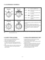
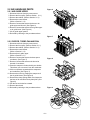
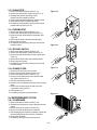
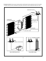
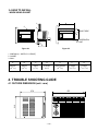
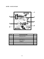
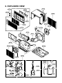
WEBSITE
E-MAIL
http://biz.LGservice.com
http://www.LGEservice.com/techsup.html
Room Air Conditioner
SERVICE MANUAL
MODEL: LWJ0561ACG
LWJ0561ACP/AAG
CAUTION
- BEFORE SERVICING THE UNIT, READ THE "SAFETY
PRECAUTIONS" IN THIS MANUAL.
- ONLY FOR AUTHORIZED SERVICE PERSONNEL.
CONTENTS
1. PREFACE
.................................................................................................................................................. 3
1.1 FEATURES ................................................................................................................................................... 3
1.2 SPECIFICATIONS ........................................................................................................................................ 3
1.3 LOCATIONS OF CONTROLS ...................................................................................................................... 4
1.4 SAFETY PRECAUTIONS ............................................................................................................................. 4
1.5 INSULATION RESISTANCE TEST .............................................................................................................. 4
2. DISASSEMBLY INSTRUCTIONS ............................................................................................... 5
2.1 MECHANICAL PARTS ................................................................................................................................. 5
2.1.1 FRONT GRILLE ................................................................................................................................... 5
2.1.2 CABINET................................................................................................................................................5
2.1.3 CONTROL BOARD .............................................................................................................................. 5
2.2 AIR HANDLING PARTS ............................................................................................................................... 6
2.2.1 AIR GUIDE UPPER ............................................................................................................................. 6
2.2.2 ORIFICE, TURBO FAN AND FAN ........................................................................................................ 6
2.2.3 MOTOR ................................................................................................................................................. 7
2.2.4 AIR GUIDE ............................................................................................................................................ 7
2.3 ELECTRICAL PARTS ................................................................................................................................... 7
2.3.1 OVERLOAD PROTECTOR .................................................................................................................. 7
2.3.2 COMPRESSOR ................................................................................................................................... 7
2.3.3 CAPACITOR ......................................................................................................................................... 8
2.3.4 THERMOSTAT ..................................................................................................................................... 8
2.3.5 ROTARY SWITCH ................................................................................................................................ 8
2.3.6 POWER CORD .................................................................................................................................... 8
2.4 REFRIGERANT CYCLE ................................................................................................................................8
2.4.1 CONDENSER ...................................................................................................................................... 8
2.4.2 EVAPORATOR ..................................................................................................................................... 9
2.4.3 CAPILLARY TUBE ............................................................................................................................... 9
3. INSTALLATION
................................................................................................................................... 11
3.1 SELECT THE BEST LOCATION ................................................................................................................ 11
3.2 CHECK OF INSTALLATION ....................................................................................................................... 11
3.3 HOW TO DRAIN ......................................................................................................................................... 11
3.4 HOW TO INSTALL ...................................................................................................................................... 12
4. TROUBLESHOOTING GUIDE
................................................................................................... 12
4.1 OUTSIDE DIMENSION .............................................................................................................................. 12
4.2 PIPING SYSTEM ....................................................................................................................................... 13
4.3 TROUBLESHOOTING GUIDE ................................................................................................................... 14
5. SCHEMATIC DIAGRAM
................................................................................................................. 19
5.1 CIRCUIT DIAGRAM .................................................................................................................................... 19
6. EXPLODED VIEW ............................................................................................................................. 21
7. SERVICE PARTS LIST ................................................................................................................... 22
—2—
1. PREFACE
This service manual provides various service information, including the mechanical and electrical parts, etc.
This room air conditioner was manufactured and assembled under a strict quality control system.
The refrigerant is charged at the factory. Be sure to read the safety precautions prior to servicing the unit.
1.1 FEATURES
•
•
•
•
•
•
DESIGNED FOR COOLING ONLY
POWERFUL AND INCREDIBLE COOLING
TOP-DOWN CHASSIS FOR THE SIMPLE INSTALLATION AND SERVICE
BUILT-IN ADJUSTABLE THERMOSTAT
WASHABLE ONE-TOUCH FILTER
COMPACT SIZE
1.2 SPECIFICATIONS
MODELS
ITEMS
LWJ0561ACG, LWJ0561ACP/AAG
COOLING CAPACITY (BTU/h)
5,000
POWER SUPPLY (Phase, V, Hz)
1Ø, 220-240V, 50HZ
INPUT (W)
625
OPERATING CURRENT (AMP.)
2.8
REFRIGERANT CONTROL
CAPILLARY TUBE
REFRIGERANT CHARGE (R-22)
200g
INSIDE FAN
OUTSIDE FAN
TURBO
PROPELLER FAN WITH SLINGER RING
AIR DISCHARGE
2-WAY (RIGHT AND LEFT)
CHASSIS
PROTECTOR
TOP-DOWN
• OVERLOAD PROTECTOR FOR COMPRESSOR
• INTERNAL PROTECTOR FOR FAN MOTOR
TEMPERATURE CONTROL
ROTARY SWITCH
THERMOSTAT
5 STEP (LOW FAN, HIGH FAN, OFF, HIGH COOL, LOW COOL)
FAN MOTOR
4 POLES, 18W
• NOTE: Specifications are subject to minor change without notice for further improvement.
—3—
1.3 LOCATIONS OF CONTROLS
Off
Operation
Operation
Off
High
Fan
FAN
High
Cool
Low
Fan
0
COO
L
( 0 ) : Turns air conditioner off.
High Fan (
) : High speed fan operation without cooling.
Low Fan
) : Low speed fan operation without cooling.
(
Low
Cool
Thermostat
Thermostat
5
COOLER
4
5
6
4
3
7
2
8
1
9
6
7
3
8
2
1
9
High Cool (
) : Cooling with high speed fan
operation.
Low Cool (
) : Cooling with low speed fan
operation.
This automatically controls the temperature of the
indoor air.
Turn the knob so that the arrow points to the
larger marks for greater cooling. Point the arrow to
the smaller marks for more moderate cooling.
(i.e. the higher the number, the greater the
cooling)
CAUTION : After switching the air conditioner from Cool to Off ( 0 ) or Fan, wait at least 3 minutes before
switching it back to Cool.
1.4 SAFETY PRECAUTIONS
1.5 INSULATION RESISTANCE TEST
1. When servicing, set the ROTARY SWITCH to
Off ( 0 ) and unplug the power cord.
2. Observe the original lead dress.
If a short circuit is found, replace all parts which
have been overheated or damaged by the short circuit.
3. After servicing, make an insulation resistance test
to prevent the customer from being exposed to
shock hazards.
1. Unplug the power cord and connect a jumper
between 2 pins (black and white).
2. The grounding conductor (green or green and yellow) is to be open.
3. Measure the resistance value with an ohm meter
between the jumpered lead and each exposed
metallic part on the equipment at all position
[except Off ( 0 )] of the ROTARY SWITCH.
4. The value should be over 1 MΩ.
—4—
2. DISASSEMBLY INSTRUCTIONS
2.1 MECHANICAL PARTS
2.1.1 FRONT GRILLE
Figure 1
1. Disconnect the unit from the power source.
2. Remove the two knobs by pulling them off.
Using a screwdriver, remove the screw that
secures the front grille to control board.
(See Figure 1)
3. Push the front grille up from the bottom.
Pull the top of the front grille away from the
cabinet as the top tabs lift out of their slots.
(See Figure 2)
4. Replace the grille by placing the tabs in the slots
and push the grille until it snaps into place.
Figure 2
Figure 3
2.1.2 CABINET
1. Disconnect the unit from the power source.
2. Remove the front grille. (Refer to Section 2.1.1)
3. Remove 9 screws that secure the cabinet to the
base and condenser. (See Figure 3)
4. Lift the cabinet from the unit.
5. Re-install by referring to the procedures above.
Figure 4
2.1.3 CONTROL BOARD
1. Disconnect the unit from the power source.
2. Remove the front grille. (Refer to Section 2.1.1)
3. Remove the cabinet. (Refer to Section 2.1.2)
4. Remove 2 screws that secure the control board to
base pan and air guide. (See Figure 4)
5. Pull the control board toward yourself.
NOTE : Controls, wires, and capacitor are now
accessible for servicing. Discharge the
capacitor before servicing.
(Refer to section 2.3.3)
Figure 5
6. Disconnect one housing terminal and 3 wires for
the fan motor and compressor. (See Figure 5)
7. Re-install components by referring to procedures
above. (Refer to wiring diagram on page 19 in this
manual or inside control board.)
—5—
2.2 AIR HANDLING PARTS
Figure 6
2.2.1 AIR GUIDE UPPER
1. Disconnect the unit from the power source.
2. Remove the front grille. (Refer to Section 2.1.1)
3. Remove the cabinet. (Refer to Section 2.1.2)
4. Remove the control board.
(Refer to Section 2.1.3)
5. Remove 2 screws that secure the brace to air
guide upper and shroud. (See Figure 6)
6. Remove 2 screws that secure the air guide upper
to air guide lower. (See Figure 6)
7. Lift air guide upper upward.
8. Re-install by referring to the procedures above.
Figure 7
2.2.2 ORIFICE, TURBO FAN AND FAN
1. Disconnect the unit from the power source.
2. Remove the front grille. (Refer to Section 2.1.1)
3. Remove the cabinet. (Refer to Section 2.1.2)
4. Remove the control board.
(Refer to Section 2.1.3)
5. Remove the air guide upper.
(Refer to Section 2.2.1)
6. Remove 2 screws that secure the base pan to
condenser. (See Figure 7)
7. Remove 2 screws that secures the shroud to
channel of condenser.
8. Press the snap area of shroud with your thumbs.
This allows you to remove it from the condenser.
9. Lift the compressor upward with the evaporator
and condenser. (See Figure 7)
10. Remove the orifice by pushing the snap area of
the air guide blower. (See Figure 8)
11. Remove the clamp springs which are clamped to
the boss of fan and turbo fan by hand plier. (See
Figure 9)
12. Pull the fan and turbo fan outward.
13. Remove the shroud.
14. Re-install by referring to the procedures above.
Figure 8
Figure 9
—6—
2.2.3 MOTOR
Figure 10
1. Disconnect the unit from the power source.
2. Remove the front grille. (Refer to Section 2.1.1)
3. Remove the cabinet. (Refer to Section 2.1.2)
4. Remove the control board. (Refer to Section 2.1.3)
5. Remove the air guide upper. (Refer to Section 2.2.1)
6. Remove the compressor, turbo fan, fan and
shroud. (Refer to Section 2.2.2)
7. Remove 2 screws that secure the motor to the motor.
(See Figure 10)
8. Remove the motor.
9. Re-install by referring to the procedures above.
2.2.4 AIR GUIDE
1. Disconnect the unit from the power source.
2. Remove the front grille. (Refer to Section 2.1.1)
3. Remove the cabinet. (Refer to Section 2.1.2)
4. Remove the control board. (Refer to Section 2.1.3)
5. Remove the air guide upper. (Refer to Section 2.2.1)
6. Remove the compressor, turbo fan, fan and shroud.
(Refer to Section 2.2.2)
7. Remove the motor. (Refer to Section 2.2.3)
8. Remove 2 screws that secure the air guide to the base
pan. (See Figure 11)
9. Push the air guide backward and lift it upward. (See Figure 11)
10. Re-install by referring to the procedures above.
Figure 11
Figure 13
Figure 12
2.3 ELECTRICAL PARTS
2.3.1 OVERLOAD PROTECTOR
1. Remove the front grille and cabinet. (Refer to Section
2.1)
2. Remove the nut which fastens the terminal cover.
3. Remove the terminal cover.
4. Remove all the leads from the overload protector.
5. Remove the overload protector.
6. Re-install the components by referring to the removal
procedure above.(See Figure 12 and 13)
2.3.2 COMPRESSOR
1. Remove the front grille and cabinet. (Refer to Section 2.1)
2. Discharge the refrigerant by using a refrigerant recovery system.
3. Remove the overload protector.(Refer to Section 2.3.1)
4. After discharging the unit completely, unbrace the suction
and discharge pipes at the compressor connections.
5. Remove 3 nuts which fasten the compressor.
6. Remove the compressor.
7. Re-install by referring to the removal procedure above. (See
Figure 14)
—7—
Figure 14
2.3.3 CAPACITOR
1. Remove the cabinet. (Refer to Section 2.1.2)
2. Remove the control board. (Refer to Section 2.1.3)
3. Discharge the capacitor by placing a 20 KΩ
resistor across the capacitor terminals.
4. Remove the screw which fastens the capacitor clamp.
5. Remove all the leads of capacitor terminals.
6. Re-install the components by referring to the removal
procedure above. (See Figure 15)
Figure 15
2.3.4 THERMOSTAT
1. Remove the cabinet. (Refer to Section 2.1.2)
2. Remove the control board. (Refer to Section 2.1.3)
3. Remove 2 screws which fasten the thermostat. (See
Figure 16)
4. Remove all the leads of the thermostat terminals.
5. Remove the thermostat.
6. Re-install the components by referring to the removal
procedure above.
Figure 16
2.3.5 ROTARY SWITCH
1. Remove the cabinet. (Refer to Section 2.1.2)
2. Remove the control board. (Refer to Section 2.1.3)
3. Remove 2 screws which fasten the rotary switch. (See
Figure 17)
4. Remove all the leads of the rotary switch terminals.
5. Remove the rotary switch.
6. Re-install the components by referring to the removal
procedure above.
Figure 17
2.3.6 POWER CORD
1. Disconnect the unit from source of power.
2. Remove the front grille. (Refer to Section 2.1.1)
3. Remove the cabinet. (Refer to Section 2.1.2)
4. Remove a screw that secures control board to base
pan. (Refer to Section 2.1.3)
5. Pulls the control board toward you.
6. Disconnect the 2 receptacles and remove the grounding
screw.
7. Remove a screw securing the clip with cord to the
control board. (See Figure 18)
8. Pull the power cord.
9. Re-install by referring to procedures above.
Figure 18
2.4 REFRIGERANT CYCLE
2.4.1 CONDENSER
1. Remove the cabinet. (Refer to Section 2.1.2)
2. Discharge the refrigerant by using a refrigerant recovery
system.
3. Remove the air guide. (Refer to Section 2.2.1)
4. Remove 2 screws which fasten the condenser.
5. After discharging the refrigerant completely, unbraze the
interconnecting tube at the condenser connections.
6. Remove the condenser.
7. Re-install by referring to the procedures above.
—8—
wise. This will keep oil from foaming and being
drawn into the vacuum pump.
2.4.2 EVAPORATOR
1. Remove the cabinet. (Refer to section 2.1.2)
2. Discharge the refrigerant by using a refrigerant
recovery system.
3. Remove the air guide upper. (Refer to Section
2.2.1)
4. After discharging the refrigerant completely,
unbraze the interconnecting tube at the evaporator
connections.
5. Remove the evaporator.
6. Re-install by referring to the procedures above.
6-3. Operate the vacuum pump for 20 to 30 minutes, until 600 micron vacuum is obtained.
Close valves A and B and observe vacuum
gauge for a few minutes.
A rise in pressure would indicate a possible
leak or moisture remaining in the system.
With valves A and B closed, stop the vacuum
pump.
6-4. Remove the hose from the vacuum pump and
place it on the charging cylinder. See figure
20B. Open valve C.
Discharge the line at the manifold connection.
6-5. The system is now ready for final charging.
2.4.3 CAPILLARY TUBE
1. Remove the cabinet. (Refer to section 2.1.2)
2. Discharge the refrigerant by using a refrigerant
recovery system.
3. Remove the air guide upper. (Refer to Section
2.2.1)
4. After discharging the refrigerant completely,
unbraze the interconnecting tube of the capillary
tube.
5. Remove the capillary tube.
6. Re-install by referring to the procedures above.
7. Recharge as follows:
7-1. Rotary compressor systems are charged from
the high-side. If the total charge cannot be put
in the high-side, the balance will be put in the
suction line through the access valve which is
installed as the system is opened.
7-2. Connect the charging cylinder as shown in figure 20B. With valve C open, discharge the
hose at the manifold connection.
7-3. Open valve A and allow the proper charge to
enter the system. Valve B is still closed.
7-4. If more charge is required, the high-side will
not take it. Close valve A.
7-5. With the unit running, open valve B and add
the balance of the charge.
a. Do not add the liquid refrigerant to the lowside.
b. Watch the low-side gauge, allow pressure to
rise to 30 lbs.
c. Turn off valve B and allow the pressure to
drop.
d. Repeat steps B and C until the balance of
the charge is in the system.
7-6. When the unit is operating correctly, use the
pinch-off tool with the unit still running and the
clamp on the pinch-off tube. Using a tube cutter, cut the pinch-off tube about 2 inches from
the pinch-off tool. Use sil-fos solder and solder
the pinch-off tube closed. Turn off the unit,
allow setting for a while and then test the leakage of the pinch-off connection.
NOTES
Replacement of the refrigeration cycle.
1. When replacing the refrigerating cycle, be sure to
discharge the refrigerant by using a refrigerant
recovery system.
2. After discharging the unit completely, remove the
desired components, and unbraze the pinch-off
tubes.
3. Solder service valves into the pinch-off tube ports,
leaving the valves open.
4. Solder the pinch-off tubes with service valves.
5. After completing the above procedures, the valve
must be closed and left in place on the system for
any subsequent procedures.
6. Evacuate as follows:
6-1. Connect the vacuum pump, as illustrated in
figure 20A.
6-2. Start the vacuum pump. Slowly open manifold
valves A and B with two full turns counterclockwise and leave the valves closed.
The vacuum pump is now pulling through
valves A and B up to valve C by means of
manifold and the entire system.
CAUTION : If high vacuum equipment is used,
just crack valves A and B for a few minutes, then
open slowly with the two full turns counter-clock—9—
Equipment needed: Vacuum pump, charging cylinder, manifold gauge, brazing equipment, pinch-off tool capable
of making a vapor proof seal, leak detector, tubing cutter, hand tools to remove components and service valve.
COMPOUND GAUGE
MANIFOLD
GAUGE
B
CONDENSER
(HIGH PRESSURE SIDE)
A
SEE INSETS
BELOW
COMPRESSOR
EVAPORATOR
(LOW PRESSURE SIDE)
CAPILLARY TUBE
LO
HI
CHARGING CYLINDER
A
B
EXTERNAL VACUUM PUMP
B
A
C
Figure 20A-Pulling Vacuum
Figure 20B-Charging
—10—
3. INSTALLATION
This air conditioner is designed with a buttondown chassis so that it can be installed simply in
a window.
3-1. SELECT THE BEST LOCATION
1. To prevent vibration and noise, make sure the unit
is installed securely and firmly.
2. Install the unit where the sunlight does not shine
directly on the unit.
3. The outside of the cabinet must extend outward for
at least 10" and there should be no obstacles,
such as a fence or wall, within 20" from the back of
the cabinet because it will prevent heat radiation of
the condenser.
Restriction of outside air will greatly reduce the
cooling efficiency of the air conditioner.
FENCE
AWNING
COOLED AIR
30"~60"
CAUTION
All side louvers of the cabinet must remain
exposed to the outside of the structure.
4. Install the unit a little slanted so the back is slightly
lower than the front (about 1/4"). This will force
condensed water to the outside.
5. Install the unit with the bottom about 30"~60"
above the floor level.
HEAT
RADIATION
ABOUT 1/4 "
Over 20"
Figure 21
3-2. CHECK OF INSTALLATION
The setting conditions must be checked prior to
initial starting.
The under mentioned items are especially
important checking points when the installation
is finished.
1. Grounding wire (Green of Green Yellow) is provided in the power cord. The green wire must be
grounded.
2. Connect to a single-outlet 15AMP circuit.
3. To avoid vibration or noise, make sure the air
conditioner is installed securely.
4. Avoid placing furniture or dreperies in front of the
air inlet and outlet.
BASE PAN
BOTTOM
1 HOLE RUBBER
Figure 22
3.3 HOW TO DRAIN
(When using drain pipe)
The air conditioner must be installed level or
titled slightly to the outside for proper water
drainage. On exceptionally hot and humid days
the air conditioner may drain condensation
water through overflow. If the air conditioner is
used in hot and a high humidity zone, exchange
the
HOLE RUBBER for the
DRAIN PIPE.
(See figure 22, figure 23)
BASE PAN
BOTTOM
2 DRAIN PIPE
Figure 23
—11—
3.4 HOW TO INSTALL
• WHEN USING GASKET
A
1
2
2
F
B
RIGHT SIDE
C
HORIZONTAL
G LINE
3
D
E
Figure 24
Figure 25
1. WINDOW (A - WIDTH, B - HEIGHT)
2. GASKET
3. WALL
A
B
C
D
E
F
G
487mm
(19 3/16")
324mm
(12 3/4")
30mm
(1 1/16")
0~25mm
(0~1")
OVER 240mm
(9 15/32")
5~10mm
(3/16"~3/8")
-5~5mm
(-3/16"~3/16")
4. TROUBLE SHOOTING GUIDE
4.1 OUTSIDE DIMENSION (unit : mm)
472
312
370
—12—
4.2 PIPING SYSTEM
CONDENSER COILS
FAN
MOTOR
CAPILLARY
TUBE
BLOWER
EVAPORATOR
COILS
Following is a brief description of the important components and their function in what is called the refrigeration
system. Reference should be made to Figure 26 to follow the refrigerating cycle and the flow of the refrigerant in
the cooling cycle.
ROOM AIR CONDITIONER
CYCLE OF REFRIGERATION
EVAPORATOR COILS
CONDENSER COILS
SUCTION LINE
COOL LOW PRESSURE VAPOR
COMPLETE LIQUID
BOIL OFF POINT
COOLED
AIR
VAPOR INLET
HOT
DISCHARGED
AIR
ROOM AIR HEAT LOAD
OUTSIDE COOLING
AIR FOR REFRIGERANT
PASS THROUGH
MOTOR
COMPRESSOR
DISCHARGE
LINE
NOT HIGH PRESSURE
VAPOR
OIL
LIQUID
PRESSURE
DROP
LIQUID OUTLET
(LIQUID REFRIGERANT)
HIGH PRESSURE VAPOR
CAPILLARY TUBE
LIQUID REFRIGERANT
LOW PRESSURE VAPOR
Figure 26
—13—
4.3 TROUBLESHOOTING GUIDE
In general, possible trouble is classified in two kinds.
The one is called Starting Failure which is caused from an electrical defect. The other is Ineffective Air
Conditioning caused from a defect in the refrigeration circuit and improper application.
Unit is running but cooling is ineffective.
Ineffective Cooling
Check cold air
circulation for smooth
flow.
Check outdoor coil
(heat exchanger) and
fan operation.
Dirty indoor coil
(heat exchanger)
Check gas leakage.
Check heat load
increase.
Clean condenser.
Not on separate circuit
Repair gas leak.
Malfunction of fan.
Clogging of air filter.
Replacement of unit if
the unit is beyond repair.
Check inside gas
pressure.
Adjust refrigerant
charge.
Obstruction at air outlet.
Remove obstruction.
Malfunction of
compressor.
Check clogging in refrigeration circuit.
Replacement of
compressor.
Repair clogging in
refrigeration circuit.
Satisfactory operation
with temperature
difference of inlet & outlet
air; 44~50°F (7~10°C)
—14—
Fails to Start
Check of power source.
Check of circuit breaker
and fuse.
Check of control switch
setting.
Gas leakage of feeler
bulb of thermostat.
Check control switch.
Compressor fails only to
start.
Fan only fails to start.
Drop of power voltage.
Improper thermostat
setting
Defect of compressor
capacitor.
Loose terminal
connection
Capacitor check.
Improper wiring
Improper wiring.
Defect of fan motor
capacitor.
Irregular motor
resistance (Ω)
Irregular motor
insulation (Ω)
Replacement.
Replacement of fan motor.
Irregular motor resistance (Ω)
Regular but fails to start.
Irregular motor insulation (Ω)
Replacement of compressor.
(Locking of piston, metal.)
Replacement of compressor
(Motor damaged).
—15—
ROOM AIR CONDITIONER VOLTAGE LIMITS
NAME PLATE RATING
MINIMUM
MAXIMUM
220V~240V
198V
264V
COMPLAINT
Fan motor will not run.
CAUSE
REMEDY
No power
Check voltage at outlet. Correct if none.
Power supply cord
Check voltage to rotary switch. If none, check
power supply cord. Replace cord if circuit is
open.
Rotary switch
Check switch continuity. Refer to wiring diagram
for terminal identification. Replace switch if
defective.
Wire disconnected or
connection loose
Connect wire. Refer to wiring diagram for
terminal identification. Repair or replace loose
terminal.
Capacitor. (Discharge
capacitor before testing.)
Test capacitor.
Replace if not within ±10% of manufacturer's
rating. Replace if shorted, open, or damaged.
Will not rotate
Fan blade hitting shroud or blower wheel hitting
scroll. Re-align assembly.
Units using slinger ring condenser fans must
have 0.22~0.25 inch clearance to the base. If it is
the base, shim up the bottom of the fan motor
with mounting screw(s).
Check fan motor bearings; if motor shaft will not
rotate, replace the motor.
Fan motor runs.
Revolves on overload.
Check voltage. See limits on this page.
If not within limits, call an electrician.
Test capacitor.
Check bearings. Does the fan blade rotate freely?
If not, replace fan motor.
Pay attention to any change from high speed to
low speed. If the speed does not change,
replace the motor.
—16—
COMPLAINT
Fan motor noise.
Compressor will not run,
fan motor runs.
CAUSE
REMEDY
Fan
If cracked, out of balance, or partially missing,
replace it.
Blower
If cracked, out of balance, or partially missing,
replace it.
Loose set screw
Tighten it.
Worn bearings
If knocking sounds continue when running or
loose, replace the motor. If the motor hums or
noise appears to be internal while running,
replace motor.
Voltage
Check voltage. See the limits on the preceding
page. If not within limits, call an electrician.
Wiring
Check the wire connections; if loose, repair or
replace the terminal. If the wires are disconnected, refer to wiring diagram for identification,
and replace the wires. Check the wire connections;
If not according to the wiring diagram, correct
the connections.
Rotary Switch
Check for continuity, refer to the wiring diagram
for terminal identification. Replace the switch if
the circuit is open.
Thermostat
Check the position of knob. If not at the coldest
setting, advance the knob to this setting and
restart the unit.
Check the continuity of the thermostat. Replace
the thermostat if the circuit is open.
Compressor cycles on
overload.
Capacitor (discharge
capacitor before
servicing.)
Check the capacitor.
Replace if not within ±10% of manufacturer’s
rating, replace if shorted, open, or damaged.
Compressor
Check the compressor for open circuit or
ground. If open or grounded, replace the
compressor.
Overload
Check the compressor overload if externally mounted.
Replace if open. (If the compressor temperature is
high, remove the overload, cool and retest.)
Voltage
Check the voltage. See the limits on the
preceding page. If voltage is not within these limits,
call an electrician.
Overload
Check overload, if externally mounted.
Replace if open. (If the compressor temperature
is high, remove the overload, cool, and retest.)
—17—
COMPLAINT
Compressor cycles on
overload
Insufficient cooling.
Excessive noise.
CAUSE
REMEDY
Fan motor
If not running, determine the cause. Replace if
required.
Condenser air flow
restriction
Remove the cabinet, inspect the interior surface
of the condenser. If restricted, clean carefully
with a vacuum cleaner (do not damage fins) or
brush. Clean the interior base before
re-assembling.
Condenser fins
(damaged)
If the condenser fins are closed over a large
area on the coil surface, head pressures will
increase, causing the compressor to cycle.
Straighten the fins or replace the coil.
Capacitor
Test the capacitor.
Wiring
Check the terminals. If loose, repair or replace.
Refrigeration system
Check the system for a restriction.
Air filter
If restricted, clean or replace.
Unit undersized
Determine if the unit is properly sized for the
area to be cooled.
Blower or fan
Check the set screw, or clamp. If loose or missing, correct. If the blower or fan is hitting scroll
or shroud, rearrange the air handling parts.
Copper tubing
Remove the cabinet and carefully rearrange the
tubing not to contact the cabinet,
compressor, shroud, and air guide.
—18—
5. SCHEMATIC DIAGRAM
5-1. CIRCUIT DIAGRAM
• MODEL : LWJ0561ACG
POWER INPUT
4
BK(BR)
(Plain)
ROTARY SWITCH
1
2 H
BK
RD
3
4 L
5
6
7
8
WH(BL)
(Ribbed)
GN(GN/YL)
BK
RD
OR(BR)
M
2
MOTOR
YL
1
CAPACITOR
YL
OR(BR)
R
3
BR
COMP.
S
C
BR
BK
RD
BL
OLP
THERMOSTAT
F
6
C
H
7
5
WIRING DIAGRAM
REF. NO
DESCRIPTION & NAME
Q'TY
1
POWER CORD ASSY
1
2
FAN MOTOR
1
3
COMPRESSOR
1
4
ROTARY SWITCH
1
5
THERMOSTAT
1
6
CAPACITOR
1
7
OVERLOAD PROTECTOR
1
—19—
• MODEL : LWJ0561ACP/AAG
1
4
2
6
3
7
5
REF. NO
DESCRIPTION & NAME
Q'TY
1
POWER CORD ASSY
1
2
FAN MOTOR
1
3
COMPRESSOR
1
4
ROTARY SWITCH
1
5
THERMOSTAT
1
6
CAPACITOR
1
7
OVERLOAD PROTECTOR
1
—20—
6. EXPLODED VIEW
130910
149410
159900-2
145200
135312
554030
159900-1
559011
152302
W48602
149980
135313
352380
346811
349480
354210
352390
W48602
130410
249950
359012
264110
552101
266003
552111
352115
352113
567502
269310
135510
554160
35211A
W0CZZ
550140
—21—
7. SERVICE PARTS LIST
LOCATION No.
DESCRIPTION
PART No.
LWJ0561ACG LWJ0561ACP LWJ0561AAG
REMARKS
130410
BASE ASSEMBLY, SINGLE
3041A10011G 3041A10011G 3041A10011G
R
130910
CABINET ASSEMBLY, SINGLE
3091A10020B 3091A10020B
3091A10020B
R
135312
GRILLE ASSEMBLY, FRONT(SINGLE) 3531AR1644C 3531AR1644L 3531AR1644Q
R
135313
GRILLE ASSEMBLY, INLET
3530AR1616A 3530AR1617A 3530AR1616A
R
135510
COVER
3550A20026A 3550A20026A
R
145200
LINK
4520AR3191A 4520AR3191A
4800A30003A
R
149410
KNOB ASSEMBLY
4941AR7315A 4941AR7315A 4941AR7315A
R
149980
SHROUD
4998A10008A 4998A10008A
4998A10008A
R
152302
FILTER(MECH), A/C
5231AR2148G 5231AR2148G 5231AR2148G
R
159900-1
VANE, VERTICAL
5990AR3190A 5990AR3190A 5990AR3190A
R
159900-2
VANE, VERTICAL
5990AR3190B 5990AR3190B 5990AR3190B
R
249950
CONTROL BOX ASSEMBLY, SINGLE
4995A20126B 4995A20126L
4995A20126L
R
264110
POWER CORD ASSEMBLY
2H01580M
3H02255E
3H02255E
R
266003
SWITCH, ROTARY
2H00154H
2H00154H
2H00154H
R
269310
THERMOSTAT ASSEMBLY
2H01109H
2H01109H
2H01109H
R
346811
MOTOR ASSEMBLY, SINGLE
4681A10002E 4681A10002E
4681A10002E
R
349480
ORIFICE
4948A10007A 4948A10007A
4948A10007A
R
352113
TUBE, DISCHARGE
5210A20511B 5210A20511B
5210A20511B
R
352115
TUBE ASSEMBLY, EVAPORATOR IN
5211A10063A 5211A10063A
35211A
TUBE ASSEMBLY, SUCTION SINGLE
5211A10062E 5211A10062E
5211A10062E
R
352380
AIR GUIDE
5238A20004A 5239A10005A
5239A10005A
R
352390
AIR GUIDE ASSEMBLY
5239A30003A 5239A30003A
5239A30003A
R
354210
EVAPORATOR ASSEMBLY, FIRST
5421A10008B 5421A10008B
5421A10008B
R
359012
FAN TURBO
5900A20005A 5900A20005A
5900A20005A
R
550140
ISOLATOR, COMP.
5040AR4195A 5040AR4195A 5040AR4195A
R
552101
TUBE, CAPILLARY
5424AR3411B 5424AR3411B
5210A30018B
R
552111
TUBE ASSEMBLY, CAPILLARY
5211AR3332R 5211AR3332R 5211AR3332R
R
554030
CONDENSER ASSEMBLY, FIRST
5403AR6200C 5403AR6200C 5403AR6200H
R
554160
COMPRESSOR
2520UAEP2FA 2520UAEP2FA 2520UAEP2FA
R
559011
FAN, PROPELLER
5900A20017A 5900A20017A
5900A20017A
R
567502
O.L.P.
6750U-L047A
6750U-L011A
R
W0CZZ
CAPACITOR, DRAWING
6120AR2194H 6120AR2194H 6120AR2194H
R
W48602
CLAMP, SPRING
3H02932B
6750U-L011A
3H02932B
R
3H02932B
NOTE) *Please ensure GCSC since these parts may be changed depending upon the buyer's request.
(GCSC WEBSITE http://[email protected])
—22—
R
P/NO:3828A20118B
April, 2002
Printed in Korea