1
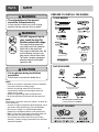
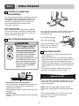
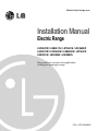
Website:http://ca.lge.com
Installation Manual
Electric Range
LSC5622W / LSB5611S / LST5601S / LSC5633W
LSC5674W / LSC5683W / LSB5682S / LST5651S
LRE3091S / LSE3094S / LSE3092S
Please read these instructions thoroughly before
installing and operating the range.
P/No.: MFL55646202
Part 1
SAFETY
1 BEFORE YOU BEGIN
Remove all tape and packing materials before using the range. Dispose all plastic bags after unpacking the range.
Never allow children to play with packing materials.
IMPORTANT SAFETY INSTRUCTIONS
Read and follow all instructions before using your oven to prevent the risk of fire, electric shock, injury to person,
or damage when using the range. This guide don’t cover all possible conditions that may occur. For further
assistance contact your service agent or manufacturer.
This is the safety alert symbol. This symbol alerts you to potential hazards that can kill or hunt you and others. All safety
messages will follow the safety alert symbol and either the word “WARNING” or “CAUTION”. These word means :
WARNING
This symbol will alert you to hazards or unsafe practices which could cause serious
bodily harm or death.
CAUTION
This symbol will alert you to hazards or unsafe practices which could cause bodily
injury or property damage.
WARNING
• The information in this manual should be followed exactly.
- A fire or electrical shock may result causing property damage, personal injury or death.
• DO NOT step or sit on the door. Install the Anti-Tip Bracket packed with range.
- The range could be tipped and injury might result from spilled hot liquid, food, or the range itself.
- If the range is pulled away from the wall for cleaning, service, or any other reason, ensure that the Anti-Tip Device is
properly reengaged when the range is pushed back against the wall.
• New branch-circuit installations (1996 NEC), mobile homes, recreational vehicles, and installations
where local codes do not allow grounding through neutral require a 4-conductor UL listed range
cord or 4 wire conduit connection.
• The middle (neutral or ground) wire of the power cord or 3-wire conduit has to be connected to the
middle post of the main terminal block. The remaining two wires of the power cord or conduit have
to be connected to the outside posts of the main terminal connection block.
- Failure to do can result in severe personal injury, death or electrical shock.
• Only a 4-conductor power-supply cord kit rated 120/240 volts, 50 amperes and marked for use with
ranges with closed-loop connectors, open-end spade lugs with upturned ends shall be used. The
middle (neutral) wire of the power cord or 4-wire conduit has to be connected to the middle post of
the main terminal block. Other two wires of the power cord or conduit have to be connected to the
outside posts of the main terminal connection block. The 4th ground wire must be connected to
the frame of the range with the ground screw.
- Failure to do can result in severe personal injury, death or electrical shock.
CAUTION
• Put on gloves during installation procedure.
- Failure to do so can result in bodily injury.
• Make sure that the wall covering, countertop and cabinets around the range can withstand the heat
(up to 194°F) generated by the range.
- Discoloration, delamination or melting may occur.
- This range has been designed to comply with the maximum allowable wood cabinet temperatures of 194°F.
• Cabinet storage space located above the surface units should be avoided.
- The risk of burns or fire by reaching over heated surface units can be eliminated.
• Install a range hood that projects horizontally a minimum of 5 inches beyond the bottom of the
cabinets If cabinet storage is to be provided.
- The risk can be reduced.
2
Part 1
SAFETY
PREPARE TO INSTALL THE RANGE
WARNING
TOOLS NEEDED
• The information in this manual
should be followed exactly.
- A fire or electrical shock may result causing
property damage, personal injury or death.
WARNING
• DO NOT step or sit on the
door. Install the Anti-Tip
Bracket packed with range.
- The range could be tipped and
injury might result from spilled hot
liquid, food, or the range itself.
- If the range is pulled away from the
wall for cleaning, service, or any
other reason, ensure that the AntiTip Device is properly reengaged
when the range is pushed back
against the wall.
Safety Glasses
Tape Measure
Gloves
Pencil
PARTS PROVIDED
CAUTION
• Put on gloves during installation
procedure.
- Failure to do so can result in bodily injury.
NOTE
• Read all instructions contained in these installation
instructions before installing range.
• Remove all packing materials from the oven
compartments before connecting the electrical
supply to the range.
• Observe all governing codes and ordinances.
• Be sure to leave these instructions with the consumer.
Rear filler & 2 Screws
(LSE Series only)
NOTE
Keep these instructions with your owner’s manual for
future reference.
• As when using any appliance generating heat, there
are certain safety precautions you should follow.
• Be sure your range is installed and grounded
properly by a qualified installer or service technician.
• Make sure the wall coverings around the range can
withstand the heat generated by the range.
• To eliminate the need to reach over the surface
elements, cabinet storage space above the elements
should be avoided.
(For Anti-Tip Bracket Mounted
on Concrete Floors and Walls)
PARTS NOT PROVIDED
3
Part 2
PREPARE TO INSTALL THE RANGE
2 INSTALLATION DRAWINGS (LRE Series only)
NOTE
SAVE FOR THE USE OF THE LOCAL ELECTRICAL INSPECTOR.
CLEARANCES AND DIMENSIONS (Figure 1)
To install range refer to the following Figure 1.
For installation in CANADA, a Free-standing range is not to be installed closer than 12mm from any
adjacent surface.
CAUTION
CAUTION
• Make sure that the wall covering,
countertop and cabinets around the
range can withstand the heat (up to
194°F) generated by the range.
• Cabinet storage space located above
the surface units should be avoided.
- The risk of burns or fire by reaching over
heated surface units can be eliminated.
- Discoloration, delamination or melting may occur.
- This range has been designed to comply with the
maximum allowable wood cabinet temperatures
of 194°F.
• Install a range hood that projects
horizontally a minimum of 5 inches
beyond the bottom of the cabinets If
cabinet storage is to be provided.
- The risk can be reduced.
A = 30”(76.2 cm) For U.S.A
= 30”(76.2 cm) ~ 31”(78.7 cm) For CANADA
FIGURE 1
FIGURE 2
MINIMUM DIMENSIONS (FIG. 2)
* 30”(76.2cm) minimum clearance between the top of the cooking surface and the bottom of an
unprotected wood or metal cabinet; or 24”(60.9cm) minimum when bottom of wood or metal cabinet is
protected by not less than 1/4”(6.4cm) flame retardant millboard covered with not less than no. 28 MSG
sheet steel, 0.015”(0.381mm) stainless steel, 0.024”(0.610mm) aluminum or 0.020”(0.508mm) copper.
** 15”(38.1cm) minimum between countertop and adjacent cabinet bottom.
4
Part 2
PREPARE TO INSTALL THE RANGE
2 INSTALLATION DRAWINGS (LSE Series only)
NOTE
SAVE FOR THE USE OF THE LOCAL ELECTRICAL INSPECTOR.
CLEARANCES AND DIMENSIONS (Figure 1)
To install range refer to the following Figure 1.
For installation in CANADA, a Free-standing range is not to be installed closer than 12mm from any
adjacent surface.
CAUTION
CAUTION
• Make sure that the wall covering,
countertop and cabinets around the
range can withstand the heat (up to
194°F) generated by the range.
• Cabinet storage space located above
the surface units should be avoided.
- The risk of burns or fire by reaching over
heated surface units can be eliminated.
- Discoloration, delamination or melting may occur.
- This range has been designed to comply with the
maximum allowable wood cabinet temperatures
of 194°F.
• Install a range hood that projects
horizontally a minimum of 5 inches
beyond the bottom of the cabinets If
cabinet storage is to be provided.
- The risk can be reduced.
24”
(60.9cm)
A = 30”(76.2 cm) For U.S.A
= 30”(76.2 cm) ~ 31”(78.7 cm) For CANADA
FIGURE 1
FIGURE 2
MINIMUM DIMENSIONS (FIG. 2)
* 30”(76.2cm) minimum clearance between the top of the cooking surface and the bottom of an
unprotected wood or metal cabinet; or 24”(60.9cm) minimum when bottom of wood or metal cabinet is
protected by not less than 1/4”(6.4cm) flame retardant millboard covered with not less than no. 28 MSG
sheet steel, 0.015”(0.381mm) stainless steel, 0.024”(0.610mm) aluminum or 0.020”(0.508mm) copper.
** 15”(38.1cm) minimum between countertop and adjacent cabinet bottom.
5
Part 3
INSTALL THE RANGE
3 ELECTRICAL CONNECTION
REQUIREMENTS
The range must be installed in accordance with Local
and Canadian Electrical Codes (latest edition). See
rating plate for total connected Amp rating. This
model was shipped direct from the factory with
Service cord attached. There are no range
connections necessary.
Note: Cord replacement
Only a range cord rated at 40 amps with 120/240
minimum volt range is required. If a 50 amp range
cord is used, it should be marked for use with 13⁄8”
diameter connection openings.
Use a spirit level to check your adjustments. Place the
level diagonally on the oven rack, and check each
direction for level.
First check direction
4 ANTI-TIP DEVICE INSTALLATION
After check direction
WARNING
1
2
.
.
If the spirit level doesn’t show
level on the rack, adjust the
leveling legs with a wrench.
• DO NOT step or sit on the
door. Install the Anti-Tip
Bracket packed with range.
5 FINAL INSTALLATION
- The range could be tipped and
injury might result from spilled hot
liquid, food, or the range itself.
- If the range is pulled away from the
wall for cleaning, service, or any
other reason, ensure that the AntiTip Device is properly reengaged
when the range is pushed back
against the wall.
• Move range close enough to the opening to plug
into the receptacle.
• Slide range into position insuring that the left back
leg slides under the anti-tip bracket. Range will sit 0”
away from the back wall when properly installed.
• Carefully tip range forward to insure that the anti-tip
bracket engages the range back brace and prevents
tip-over.
• Turn on electrical power. Check range for proper
operation as described in owner’s manual.
Optional rear filler
If the counter does not bridge the opening at the rear
wall the rear filler kit, that is provided with the slide in
range, will be needed.
1. Locate the bracket using the template
An Anti-tip bracket is packaged with template. The
instructions include necessary information to
complete the installation.
Read and follow range installation instruction sheet
(template).
2. Level the range
Level the range by adjusting the leveling legs with a
wrench.
NOTE : If the countertop depth is greater than 25”
there will be a gap between the filler kit and the back
wall.
If the countertop depth is less than 24”, the control
panel will not sit flush with the countertop.
(See figure 1 on page 5)
6