1
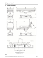
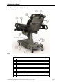
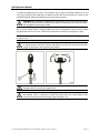
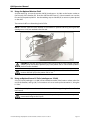
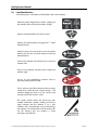
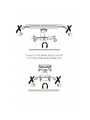
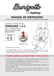
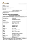
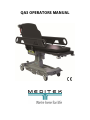
QA3 OPERATORS MANUAL
QA3 Operators Manual
Contents
Page
1. Introduction
.
.
.
.
.
.
.
.
1
1.1.
Warnings & Cautions
.
.
.
.
.
.
1
1.2.
Scope of Use
.
.
.
.
.
.
1
1.3.
Equipment Classification .
.
.
.
.
.
1
1.4.
Serial Number Label
.
.
.
.
.
.
1
2. Summary of Warnings and Cautions .
.
.
.
.
.
2
3. Product Specifications
.
.
.
.
.
.
4
4. Patient Stretcher Product Functions .
.
.
.
.
.
6
5. Emergency Stretcher Product Functions
.
.
.
.
.
7
6. Height Adjustment .
.
.
.
.
.
.
.
8
7. Using the Brakes
.
.
.
.
.
.
.
8
8. Using the Steering Pedal
.
.
.
.
.
.
.
8
9. Using the Stretchers Sides
.
.
.
.
.
.
.
9
10. Using the Backrest .
.
.
.
.
.
.
.
9
.
.
.
.
.
.
9
12. Using the fold-away Pushing Handles
.
.
.
.
.
10
13. Using the I.V. Pole
.
.
.
.
.
10
14. Additional Features of Emergency Stretcher .
.
.
.
.
12
15. Patient Weight Limit .
.
.
.
.
.
.
.
12
16. K8 Pressure Care Mattress
.
.
.
.
.
.
.
13
17. Cleaning and Disinfecting the Stretcher
.
.
.
.
.
13
18. Using the Optional Monitor Shelf
.
.
.
.
.
.
14
19. Using an Optional Loose I.V. Pole
.
.
.
.
.
.
14
20. Product Warranty
.
.
.
11. Using the Trendelenburg Function
.
.
.
.
.
.
.
.
.
.
.
15
21. Product Maintenance
.
.
.
.
.
.
.
15
22. Label Identification .
.
.
.
.
.
.
.
16
© Portsmouth Surgical Equipment Ltd and Anetic Aid Ltd. All rights reserved; this document is not to be reproduced in whole or in part
without the permission of the copyright owners. The company reserves the right to modify or improve the equipment referred to.
QA3 Operators Manual
1.
Introduction
These instructions are intended to assist you with the operation of the QA3 Patient Stretcher and the
QA3 Emergency Stretcher and it is important that they are read thoroughly before using the
equipment.
It is also important to check the stretcher before use to ensure there is no loss or change in
performance; ensure that all stretcher functions operate to their full range of movement and that all
components disengage, re-engage and lock correctly. We recommend that the stretcher is visually
inspected for any loose or damaged parts, foreign objects caught in the castors, and hydraulic fluid
leakage.
1.1.
Warnings & Cautions
Various warnings and cautions are made throughout these operating instructions.
A WARNING is given when the personal safety of the patient or user may be affected and
when disregarding this information could result in injury.
A CAUTION is given when special instructions must be followed. Disregarding this
information could result in permanent damage being caused to the stretcher.
1.2.
Scope of Use
This product is intended for transporting patients and can also be used for examinations,
intubations, radiography and recovering patients from anaesthesia.
CAUTION: The stretcher may be damaged by pushing it across rough or uneven ground.
1.3.
Equipment Classification
This stretcher has been classified as a ‘Class 1’ medical device.
1.4.
Serial Number Label
The serial number label is located on the base cover moulding; see Fig. 2 for the exact location.
© Portsmouth Surgical Equipment Ltd. Document No. 992004. Issue 24 – 27.04.12
Page 1
QA3 Operators Manual
2.
Summary of Warnings and Cautions
NOTE: All patient stretchers with moving parts are susceptible to pinch points. Whilst every effort
has been taken to eliminate these risks, care should be taken when using the stretcher.
WARNING: Ensure there is nothing to impede the raising or lowering of the patient
platform as this could result in damage to the equipment and/or injury to the patient.
WARNING: When leaving patients unattended the stretcher should be fully lowered to
minimise any risk of injury should the patient fall off the stretcher.
WARNING: Always apply the brakes when a patient is getting on or off the stretcher, or
when transferring patients from the stretcher to another platform.
WARNING: After raising the stretcher side, it is important to ensure that it has locked in
position by pushing down on the stretcher side; failure to ensure the stretcher side is
properly locked could result in injury to the patient.
WARNING: Exceeding the maximum specified patient weight limit could result in failure
of the stretcher and injury to the patient and/or user.
WARNING: Exceeding the maximum specified weight limit could result in failure of the
monitor shelf and injury to the patient and/or user.
CAUTION: Applying the steering pedal with excessive force, i.e. by standing on it, will
cause permanent damage to the mechanism.
CAUTION: The steering pedal is designed to disengage automatically when the stretcher
is pushed foot end first over an obstruction. Attempting to prevent this will cause
damage to the mechanism. The steering pedal should be allowed to disengage and then
can be reengaged after negotiating the obstruction.
CAUTION: The steering pedal must be disengaged manually when the stretcher is
pushed or pulled head end first over an obstruction, i.e. an elevator threshold, or damage
may occur.
CAUTION: If the stretcher side mounted I.V. pole is in use when either raising or lowering
the stretcher side it is important to check the infusion flow rate as the height of the
infusion above the patient will change by approximately 11.75”.
CAUTION: When the backrest is raised the fold-away pushing handles can come in close
proximity to the patient’s head and care should be taken.
CAUTION: When folding the I.V. pole away ensure that it is fully retracted and returned to
its storage position within the stretcher side; failure to do this may cause the pole to get
caught on obstructions when pushing the stretcher.
CAUTION: When adjusting the height of the I.V. pole use two hands; one to adjust the
height of the inner pole and hooks, and the other to hold the outer pole to ensure that it
remains fully engaged in the mounting socket.
© Portsmouth Surgical Equipment Ltd. Document No. 992004. Issue 24 – 27.04.12
Page 2
QA3 Operators Manual
CAUTION: Using the I.V. pole to either push or pull the stretcher may cause permanent
damage to the I.V. pole and the stretcher side.
CAUTION: Do not raise the backrest with the X-Ray tray, X-Ray cassette or digital plate
across the backrest hinge as damage may occur.
CAUTION: Ensure that the mattress is correctly orientated on the patient platform with
the Velcro® of the mattress aligning with the Velcro® on the patient platform.
CAUTION: Ensure that the mattress is centrally positioned across the width of the patient
platform otherwise it may prevent the stretcher side from locking when raised.
CAUTION: Disinfectant products are corrosive in nature; failure to properly wash and dry
the stretcher surfaces could leave a corrosive residue which may cause damage to the
stretcher.
CAUTION: Do not steam clean or jet wash any areas of the stretcher.
CAUTION: Do not use concentrated bleaching disinfectant solutions, organic solvents,
abrasive powders or expose any part of the stretcher to excessive heat.
CAUTION: Ensure that any items placed on the monitor shelf are safely secured using the
webbing strap and buckle to prevent injury to the patient and/or user should the patient
platform need to be tilted.
CAUTION: Using the loose I.V. pole to either push or pull the stretcher may cause
permanent damage to the I.V. pole.
CAUTION: Maintenance work should only be conducted by suitably trained personnel
following manufacturer’s guidelines.
© Portsmouth Surgical Equipment Ltd. Document No. 992004. Issue 24 – 27.04.12
Page 3
QA3 Operators Manual
3.
Product Specifications
Fig. 1
© Portsmouth Surgical Equipment Ltd. Document No. 992004. Issue 24 – 27.04.12
Page 4
QA3 Operators Manual
QA3 Patient Stretcher
QA3 Emergency Stretcher
Catalogue No. 21110
Catalogue No. 21120
Castor Diameter
6”
8”
6”
8”
Minimum Stretcher Height
18.75”
20.5”
20.5”
22.25”
A.
Maximum Stretcher Height
30.5”
32.25”
32.25”
34”
NOTE: Height is measured from the floor to the patient platform and does not include the mattress.
Ground Clearances Under the Stretcher Base:
Under the 5th Wheel Pedal Mechanism
3.5”
3.5”
3.5”
3.5”
B.
at the Head End of the Stretcher
Under the Base Frame at the Foot End
3.5”
5.25”
3.5”
5.25”
C.
of the Stretcher
1.75”
3.5”
1.75”
3.5”
D. Under the Lifting Column
NOTE: The ground clearance figures quoted are general guidelines; as per Fig. 1 the stretcher is
compatible with hoists with leg heights up to 4.75” on either castor option, 6” or 8”.
Stretcher Weight
260 lbs.
265 lbs.
300 lbs.
305 lbs.
79.75”
E. Mattress Length
27.75”
F. Mattress Width
3.5”
G. Mattress Depth
Stretcher Length:
84”
H. Patient Platform Flat
71.75”
I. Backrest Raised
31.75”
J. Stretcher Width Stretcher Sides Up
Stretcher Width Stretcher Sides Down
29”
K.
Stretcher Width Brakes Off
29”
29.25”
L. Width between Stretcher Sides Up
Trendelenburg
14°
Reverse Trendelenburg
10°
0°
- 90°
M. Backrest Articulation
I.V. Pole:
83”
84.75”
N. Maximum Height of Pole
Maximum Weight per Hook
6.5 lbs. (3 Litres)
Safe Working Load
13 lbs.
Maximum Patient Weight:
550 lbs.
Safe Working Load
630 lbs.
NOTE: The safe working load is the sum of the maximum patient weight, the weight of any
accessories attached to the stretcher and the weight of the items on or attached to those
accessories.
Maximum Weight Limit on the Monitor
55 lbs.
Shelf
NOTE: The monitor shelf is an optional accessory (catalogue no. 21150)
Environmental Conditions
Temperature:
Operation
10°C to 50°C
Storage & Transport
-20°C to 50°C
Relative Humidity:
Operation
30% to 75%
Storage & Transport
10% to 75%
Atmospheric Pressure:
Operation
70kPa to 106kPa
Storage & Transport
50kPa to 106kPa
Key to Fig. 1
© Portsmouth Surgical Equipment Ltd. Document No. 992004. Issue 24 – 27.04.12
Page 5
QA3 Operators Manual
4.
Patient Stretcher Product Functions
Fig. 2
Key to Fig. 2
1.
Backrest Actuation Lever
2.
Trendelenburg Actuation Lever
3.
Steering Pedal (activates 5th wheel)
4.
Brake Pedal
5.
Raise and Lower Pedal
6.
Stretcher Side
7.
Stretcher Side Release Lever
8.
Fixed I.V. Pole
9.
Fold-away Pushing Handles
10.
Fixed Pushing Handles
11.
Oxygen Cylinder Mounting Trough
NOTE: A CD cylinder support bracket is available (catalogue no. 53556)
12.
Storage Recess
© Portsmouth Surgical Equipment Ltd. Document No. 992004. Issue 24 – 27.04.12
Page 6
QA3 Operators Manual
5.
Emergency Stretcher Product Functions
Fig. 3
Key to Fig. 3 - See QA3 Patient Stretcher specification for standard features (Fig. 2)
13.
X-Ray Platform
14.
Additional Fixed I.V. Pole
15.
‘V’ Mounting for 1 Litre Suction Canister
16.
Optional Monitor Shelf (catalogue no. 21151)
NOTE: Fig. 3 shows the stretcher fitted with an F size cylinder, a 1 litre suction
canister and two I.V. bags; these items are not supplied with the stretcher.
© Portsmouth Surgical Equipment Ltd. Document No. 992004. Issue 24 – 27.04.12
Page 7
QA3 Operators Manual
6.
Height Adjustment
The height of the patient platform is adjusted by using either of the raise and lower pedals (Fig. 2,
no. 5). Pumping either pedal will raise the patient platform, lifting either pedal will lower the patient
platform.
WARNING: Ensure there is nothing to impede the raising or lowering of the patient
platform as this could result in damage to the equipment and/or injury to the patient.
WARNING: When leaving patients unattended the stretcher should be fully lowered to
minimise any risk of injury should the patient fall off the stretcher.
7.
Using the Brakes
All four castors are simultaneously braked by depressing either of the brake pedals at any point
along the length of the pedal (Fig. 2, no. 4). The brakes are disengaged by lifting either pedal.
WARNING: Always apply the brakes when a patient is getting on or off the stretcher, or
when transferring patients from the stretcher to another platform.
8.
Using the Steering Pedal
The stretcher can be manoeuvred more easily by engaging the 5th wheel steering mechanism (Fig. 2,
no. 3); the mechanism is engaged by pressing down on the steering pedal and disengaged by lifting
the pedal. To move the stretcher sideways disengage the 5th wheel.
CAUTION: Applying the steering pedal with excessive force, i.e. by standing on it, will
cause permanent damage to the mechanism.
CAUTION: The steering pedal is designed to disengage automatically when the stretcher
is pushed foot end first over an obstruction. Attempting to prevent this will cause
damage to the mechanism. The steering pedal should be allowed to disengage and then
can be reengaged after negotiating the obstruction.
CAUTION: The steering pedal must be disengaged manually when the stretcher is
pushed or pulled head end first over an obstruction, i.e. an elevator threshold, or damage
may occur.
© Portsmouth Surgical Equipment Ltd. Document No. 992004. Issue 24 – 27.04.12
Page 8
QA3 Operators Manual
9.
Using the Stretcher Sides
The stretcher is supplied with two sides that can be individually raised and lowered (Fig. 2, no. 6).
Lower the stretcher side by pulling up on the stretcher side release lever (Fig. 2, no. 7) and pushing
the stretcher side down. Raise the stretcher side by gripping it and pulling up firmly; the stretcher
side will automatically lock in position.
NOTE: The stretcher sides are designed to prevent a patient inadvertently rolling off the stretcher;
they are not intended to restrain the patient.
NOTE: When the I.V. pole is in use, the weight of the stretcher side is increased and the stretcher
side may lower more quickly. Keep a firm grip on the stretcher side as it lowers to control its
movement; see section 13, ‘Using the I.V. Pole’ for details on the maximum weight for the I.V. pole.
CAUTION: If the stretcher side mounted I.V. pole is in use when either raising or lowering
the stretcher side it is important to check the infusion flow rate as the height of the
infusion above the patient will change by approximately 11.75”.
WARNING: After raising the stretcher side, it is important to ensure that it has locked in
position by pushing down on the stretcher side; failure to ensure the stretcher side is
properly locked could result in injury to the patient.
10.
Using the Backrest
The backrest is moved up or down by pulling up on the backrest actuation lever (Fig. 2, no. 1) while
keeping a firm grip on the pushing handle to control the movement.
NOTE: It is important to note that the backrest provides only minimal lift assistance; the patient
should be assisted into a sitting position as the backrest is articulated up.
CAUTION: When the backrest is raised the fold-away pushing handles can come in close
proximity to the patient’s head and care should be taken.
11.
Using the Trendelenburg Function
The patient platform can be moved into a Trendelenburg position by pulling up on the
Trendelenburg actuation lever (Fig. 2, no. 2) whilst maintaining a firm grip on the platform handle to
control the movement. The tilt speed can be controlled by the gradual squeezing of the actuation
lever rather than pulling it fully.
WARNING: When handling heavy patients, extreme care should be taken when
attempting to tilt the platform head down and assistance should be sought to take the
weight of the platform when released; failure to do so could result in injury to the user.
© Portsmouth Surgical Equipment Ltd. Document No. 992004. Issue 24 – 27.04.12
Page 9
QA3 Operators Manual
12.
Using the fold-away Pushing Handles
The stretcher is fitted with two fold-away pushing handles at the head end of the stretcher (Fig. 2,
no. 9).
NOTE: It is an option to have fold-away pushing handles installed on the foot end of the stretcher
(catalogue no. 21155).
As illustrated in Fig. 4 each pushing handle is swivelled out (A), up (B), and then allowed to drop
down into the mounting socket ready for use (C). The handles should be folded away when not in
use.
CAUTION: When the backrest is raised the fold-away pushing handles can come in close
proximity to the patient’s head and care should be taken.
13.
Using the I.V. Pole
The Patient Stretcher is supplied with one fixed I.V. pole fitted into the patient’s left hand stretcher
side (Fig. 2, no. 8). The Emergency Stretcher is supplied with two fixed I.V. poles, one on each
stretcher side.
To use the I.V. pole, as illustrated in Fig. 5; pull the I.V. pole away from the stretcher side storage
position (A), articulate the I.V. pole up 90 degrees to the vertical position (B), and allow the I.V. pole
to drop down and engage into the mounting socket (C).
© Portsmouth Surgical Equipment Ltd. Document No. 992004. Issue 24 – 27.04.12
Page 10
QA3 Operators Manual
To adjust the height of the I.V. pole, as illustrated in Fig. 6; grasp the locking mechanism (A) and
using your thumb, lift the mechanism to release the lock and move the pole up or down to the
required height (B); release the mechanism to lock the pole in position.
CAUTION: When adjusting the height of the pole use two hands; one to adjust the height
of the inner pole and hooks, and the other to hold the outer pole to ensure that it remains
fully engaged in the mounting socket.
The I.V. pole is fitted with two spring-loaded hooks that are designed to return to their original
upright position when not in use. Swivel one or both hooks outwards (C) to hang the I.V. bags.
NOTE: The maximum weight limit per I.V. hook is 6.5 lbs. or 3 litres, and the safe working load for the
I.V. pole is 13 lbs.
CAUTION: When folding the I.V. pole away ensure that it is fully retracted and returned to
its storage position within the stretcher side; failure to do this may cause the pole to get
caught on obstructions when pushing the stretcher.
CAUTION: Using the I.V. pole to either push or pull the stretcher may cause permanent
damage to the I.V. pole and the stretcher side.
CAUTION: If the stretcher side mounted I.V. pole is in use when either raising or lowering
the stretcher side it is important to check the infusion flow rate as the height of the
infusion above the patient will change by approximately 11.75”.
© Portsmouth Surgical Equipment Ltd. Document No. 992004. Issue 24 – 27.04.12
Page 11
QA3 Operators Manual
14.
Additional Features of Emergency Stretcher
The QA3 Emergency Stretcher is specially designed to accommodate the needs of accident and
emergency departments and includes: a raised X-Ray translucent platform (Fig. 3, no. 13), an
additional fixed I.V. pole fitted into the patient’s right hand stretcher side (Fig. 3, no. 14) and a
suction system mounting ‘V’ bracket (Fig. 3, no. 15).
NOTE: The following options are available: X-Ray tray (catalogue no. 21195), X-Ray guide strips
(catalogue no. 21196) and X-Ray graduation labels (catalogue no. 21197)
X-Ray cassettes and digital plates are loaded beneath the X-Ray platform and can be positioned
anywhere beneath the platform. Alternatively the X-Ray cassettes and digital plates can be loaded
on the optional X-Ray tray and then positioned anywhere beneath the platform.
To improve access for cleaning beneath the X-Ray platform both the backrest section (A) and the leg
section (B) articulate upwards, as illustrated in Fig. 7.
CAUTION: Do not raise the backrest with the X-Ray tray, X-Ray cassette or digital plate
across the backrest hinge as damage may occur.
15.
Patient Weight Limit
The stretcher is designed to accommodate a maximum patient weight of 550 lbs. and has a safe
working load of 630 lbs.
NOTE: The safe working load is the sum of the maximum patient weight, the weight of any
accessories attached to the stretcher and the weight of the items on or attached to those
accessories.
WARNING: Exceeding the maximum specified patient weight limit could result in failure
of the stretcher and injury to the patient and/or user.
© Portsmouth Surgical Equipment Ltd. Document No. 992004. Issue 24 – 27.04.12
Page 12
QA3 Operators Manual
16.
K8 Pressure Care Mattress
Each mattress part is fixed to the patient platform with Velcro®; this enables the mattress sections to
be removed from the stretcher for cleaning and replacement.
NOTE: The mattress parts should be visually inspected for damage on a daily basis. If the outer
mattress fabric is torn, then fluids may penetrate and the mattress should be replaced. Do not
attempt to repair tears or splits with self adhesive tapes.
CAUTION: Ensure that the mattress is correctly orientated on the patient platform with
the Velcro® of the mattress aligning with the Velcro® on the patient platform.
CAUTION: Ensure that the mattress is centrally positioned across the width of the patient
platform otherwise it may prevent the stretcher side from locking when raised.
17.
Cleaning and Disinfecting the Stretcher
Clean the stretcher with warm water and neutral detergent and dry the surfaces thoroughly using a
soft cloth. Apply disinfectant by spray or disinfectant wipe, do not soak or immerse the stretcher.
Suitable disinfectants are: quaternary ammonium compounds, isopropyl alcohol, chlorine bleach
0.5% and phenolics. Following disinfection, wash off the stretcher surfaces with clean warm water
and dry thoroughly using a soft cloth.
NOTE: It is recommended that only CE marked cleaning products are used in the cleaning of this
stretcher.
NOTE: Dilute all disinfectants in accordance with the manufacturer’s guidelines.
CAUTION: Disinfectant products are corrosive in nature; failure to properly wash and dry
the stretcher surfaces could leave a corrosive residue which may cause damage to the
stretcher.
CAUTION: Do not steam clean or jet wash any areas of the stretcher.
CAUTION: Do not use concentrated bleaching disinfectant solutions, organic solvents,
abrasive powders or expose any part of the stretcher to excessive heat.
© Portsmouth Surgical Equipment Ltd. Document No. 992004. Issue 24 – 27.04.12
Page 13
QA3 Operators Manual
18.
Using the Optional Monitor Shelf
As illustrated in Fig. 8, insert the monitor shelf (A) (catalogue no. 21150) in to the location sockets at
the foot end of the stretcher (B). Pivot the shelf over the frame (C) so that it extends out over the
foot end of the patient platform. Use the webbing strap and buckle (D) to secure any items placed
on the shelf.
The monitor shelf has a safe working load of 55 lbs.
NOTE: A monitor shelf cannot be attached to the stretcher if optional fold-away pushing handles
(catalogue no. 21155) are attached to the foot end.
CAUTION: Ensure that any items placed on the monitor shelf are safely secured using the
webbing strap and buckle to prevent injury to the patient and/or user should the patient
platform need to be tilted.
WARNING: Exceeding the maximum specified weight limit could result in failure of the
monitor shelf and injury to the patient and/or user.
19.
Using an Optional Loose I.V. Pole (catalogue no. 21160)
A loose I.V. pole (catalogue no. 21160) can be inserted into either of the location sockets at the foot
end of the stretcher; see Fig. 8 (B). For instructions on how to use the pole see section 13, ‘Using the
I.V. Pole’.
NOTE: A loose I.V. pole cannot be used with the stretcher if fold-away pushing handles are fitted to
the foot end.
CAUTION: Using the loose I.V. pole to either push or pull the stretcher may cause
permanent damage to the I.V. pole.
© Portsmouth Surgical Equipment Ltd. Document No. 992004. Issue 24 – 27.04.12
Page 14
QA3 Operators Manual
20.
Product Warranty
The product, when new, is guaranteed to be free from defects in materials and workmanship and to
perform in accordance with the manufacturer’s specification for a period of one (1) year from the
date of purchase from Meditek. Meditek will repair or replace, at their discretion, any components
found to be defective or at variance with the manufacturer’s specification within this time frame at
no cost to the purchaser.
The warranty will take effect from the date of purchase, subject to the purchaser registering the
product with Meditek to confirm its receipt, installation date and product details.
The warranty does not provide cover for breakage or failure due to tampering, misuse, neglect,
accidents, modifications or shipping. The warranty is also void if the product is not used in
accordance with the manufacturer’s instructions or is repaired during the warranty period by any
persons other than Meditek or its appointed agent. No other expressed or implied warranty is given.
For details of our extended warranty packages please contact Meditek.
21.
Product Maintenance
It is recommended that the stretcher is serviced on an annual basis in accordance with the
manufacturer’s service schedule.
Before use, ensure all stretcher functions operate to their full range of movement and that all
components disengage, re-engage and lock correctly. Also visually inspect the stretcher for any
loose or damaged parts, foreign objects caught in the castors and hydraulic fluid leakage.
CAUTION: Maintenance work should only be conducted by suitably trained personnel
following manufacturer’s guidelines.
© Portsmouth Surgical Equipment Ltd. Document No. 992004. Issue 24 – 27.04.12
Page 15
QA3 Operators Manual
22.
Label Identification
The following list is a description of all the labels used on the stretcher;
Maximum patient weight limit is 550 lbs. (250kg) and
the stretcher safe working load is 630 lbs. (285kg).
Depress the brake pedal to lock all four castors.
Depress the steering pedal to engage the 5th wheel
steering function.
Pump the raise and lower pedal to raise the patient
platform, lift the raise and lower pedal to lower the
patient platform.
Lift the side stretcher side release lever to lower the
stretcher side.
Pull up on the backrest actuation lever to adjust the
backrest angle.
Pull up on the Trendelenburg actuation lever to
adjust the patient platform angle.
The I.V. pole must be fully inserted into the mounting
socket to be locked into the vertical position. The
maximum weight per hook is 6.5 lbs. and the safe
working load for the I.V. pole is 13 lbs.
The screen printed Anetic Aid brand logo with
multiple information symbols (reading from left to
right); indicates that the mattress is for a QA3
Stretcher and is manufactured using K8 technology,
the mattress is CE marked, refer to the instructions for
use (for cleaning etc.), the mattress is X-Ray
translucent and latex free.
© Portsmouth Surgical Equipment Ltd. Document No. 992004. Issue 24 – 27.04.12
Page 16
1810 Ellice Avenue
Winnipeg, MB R3H 0B7
T 1.800.567.8400
F 1.204.779.4900
www.mediteksurgical.com
1-10/15/2012