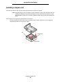
1
4600 MFP Option Printer and Scanner Setup Guide for the T640, T642, and T644 series printers April 2006 www.lexmark.com Stability Information CAUTION: Floor-mounted configurations require additional furniture for stability. You must use either a printer stand or caster base if you are using a 2000-sheet drawer. Certain other configurations also must have a printer stand or caster base. More information is available on our Lexmark Web site at www.lexmark.com/multifunctionprinters. VOORZICHTIG: Voor configuraties die op de grond staan, zijn extra onderdelen nodig ter bevordering van de stabiliteit. Als u een lader voor 2000 vel gebruikt, dient u een printerstandaard of een printerbasis te gebruiken. Bepaalde andere configuraties moeten ook een printerstandaard of printerbasis hebben. Meer informatie is beschikbaar op de website van Lexmark op www.lexmark.com/multifunctionprinters. ATTENTION : les configurations posées sur le sol nécessitent un meuble supplémentaire pour assurer leur stabilité. Vous devez utiliser un support ou une base d'imprimante si vous utilisez un bac 2 000 feuilles. Certaines autres configurations doivent également disposer d'un support ou d'une base d'imprimante. Vous trouverez des informations supplémentaires sur le site Web de Lexmark à l'adresse suivante : www.lexmark.com/multifunctionprinters. VORSICHT: Für auf dem Boden stehende Drucker ist aus Stabilitätsgründen ein zusätzlicher Untersatz erforderlich. Verwenden Sie bei Druckern mit einer 2000-Blatt-Papierzuführung ein Druckergestell oder eine Druckerbasis. Für andere Konfigurationen ist ebenfalls ein Druckergestell oder eine Druckerbasis erforderlich. Weitere Informationen finden Sie auf der Lexmark Website unter www.lexmark.com/multifunctionprinters. ATTENZIONE: Le configurazioni con installazione a terra richiedono componenti aggiuntivi per garantire una stabilità maggiore. Se si utilizza un cassetto da 2000 fogli, è necessario utilizzare un supporto o una base per la stampante. Anche altre configurazioni devono disporre di un supporto o di una base per la stampante. Per ulteriori informazioni, visitare il sito Web Lexmark all'indirizzo www.lexmark.com/multifunctionprinters. PRECAUCIÓN: para las configuraciones que se vayan a colocar en el suelo se necesita un mueble adicional para proporcionar estabilidad. Para poder utilizar un alimentador de 2000 hojas, debe utilizar un soporte o base de impresora. Existen otras configuraciones que también necesitan un soporte o base de impresora. Obtendrá más información en el sitio Web de Lexmark en www.lexmark.com/multifunctionprinters. PRECAUCIÓ: per a les disposicions muntades sobre el terra cal mobiliari addicional per aconseguir estabilitat. Heu d'utilitzar una base o suport per a impressora si feu servir un alimentador per a 2000 fulls. D'altres configuracions han de tenir també una base o suport per a impressora. Trobareu més informació a la pàgina Web de Lexmark: www.lexmark.com/multifunctionprinters. CUIDADO: As configurações com montagem no chão requerem móveis adicionais para que a estabilidade seja assegurada. Tem de utilizar um suporte ou uma base para impressora se estiver a utilizar uma gaveta de 200 folhas. Outras configurações também têm de ter um suporte ou uma base de impressora. Mais informações disponíveis no Web site da Lexmark em www.lexmark.com/multifunctionprinters. CUIDADO: As configurações cuja montagem é feita no chão exigem mobília adicional para maior estabilidade. Use um suporte ou uma base para impressora caso esteja utilizando uma gaveta para 2.000 folhas. Algumas outras configurações também exigem um suporte ou uma base para impressora. Mais informações estão disponíveis no site da Lexmark, em www.lexmark.com/multifunctionprinters. VAR FÖRSIKTIG: Om skrivaren är placerad på golvet krävs ytterligare möbler för att den ska stå stabilt. Du måste använda ett skrivarställ eller en skrivarbas om du använder en 2000-arkmatare. Vissa andra konfigurationer måste också ha ett skrivarställ eller skrivarbas. Mer information finns på Lexmarks webbplats www.lexmark.com/multifunctionprinters. FORSIGTIG: Gulvbaserede konfigurationer kræver ekstra møbler for at gøre den pågældende konfiguration mere stabil. Du skal bruge et printerbord eller et printerstativ, hvis du bruger skuffen til 2.000 ark. Visse andre konfigurationer skal også bruge et printerbord eller et printerstativ. Du kan få yderligere oplysninger på vores websted www.lexmark.com/multifunctionprinters Stability Information 1 VAARA: Lattialle asennettu tulostin edellyttää lisätukea. Tulostinjalustaa tai -tukea on käytettävä, jos monitoimilaitteeseen on asennettu 2000 arkin syöttölaite Myös tietyissä muissa kokoonpanoissa on käytettävä tulostinjalustaa tai -tukea. Lisätietoja on Lexmarkin Web-sivuilla osoitteessa www.lexmark.com/multifunctionprinters. FORSIKTIG: Gulvmonterte konfigurasjoner krever ekstra møbelenheter som støtter og stabiliserer skriveren. Du må bruke et skriverstativ eller en skriversokkel hvis du bruker en 2000 arks skuff. Andre konfigurasjoner må også ha skriversokkel eller skriverbase. Du kan finne mer informasjon på Lexmarks internasjonale hjemmeside www.lexmark.com/multifunctionprinters. UWAGA: Konfiguracje montowane na pod³odze wymagaj¹ zastosowania dodatkowych elementów w celu zachowania stabilnoœci. W przypadku korzystania z szuflady na 2000 arkuszy konieczne jest zastosowanie stojaka lub podstawy drukarki. Niektóre inne konfiguracje równie¿ wymagaj¹ zastosowania stojaka lub podstawy. Wiêcej informacji mo¿na znaleŸæ w witrynie internetowej firmy Lexmark pod adresem: www.lexmark.com/multifunctionprinters. ВНИМАНИЕ! Конфигурации, предусматривающие установку на полу, требуют дополнительных конструкций для обеспечения устойчивости. При работе с выдвижным лотком на 2000 листов следует использовать стойку принтера или основание принтера. Для установки некоторых других конфигураций также требуется стойка принтера или основание принтера. Дополнительная информация представлена на web-узле корпорации Lexmark по адресу www.lexmark.com/multifunctionprinters. UPOZORNÌNÍ: Sestavy usazené na podlahu potøebují kvùli stabilitì další díl. Pokud používáte zásobník na 2000 listù, je nutné použít buï stojan pod tiskárnu nebo podstavec tiskárny. Nìkteré další sestavy také vyžadují stojan pod tiskárnu nebo podstavec tiskárny. Další informace jsou uvedeny na webové stránce spoleènosti Lexmark na adrese www.lexmark.com/multifunctionprinters. POZOR: Konfigurácie, ktoré sa inštalujú na podlahu, vyžadujú kvôli stabilite doplnkové vybavenie. Ak používate zásuvku na 2 000 listov, musíte použit' buï stojan tlaèiarne alebo základnú skrinku tlaèiarne. Pri niektorých iných konfiguráciách musíte takisto použit' stojan tlaèiarne alebo základnú skrinku tlaèiarne. Viac informácií je dostupných na našej webovej stránke spoloènosti Lexmark na adrese www.lexmark.com/multifunctionprinters. FIGYELEM! A padlóra állított készülékek stabil elhelyezése érdekében támasztékra van szükség. 2000 lapos fiók esetén alkalmazzon nyomtatóállványt. Egyes más konfigurációk is igényelhetik a nyomtatóállvány használatát. További információkat a Lexmark webhelyén olvashat a www.lexmark.com/multifunctionprinters címen. DÝKKAT: Zemine monte edilen yapýlandýrmalarýn dengesini korumak için ek mobilyalar gerekir. 2000-yapraklýk bir çekmece kullanýyorsanýz, bir yazýcý sehpasý veya yazýcý altlýðý kullanmanýz gerekir. Tüm diðer yapýlandýrmalarda da bir yazýcý sehpasý veya yazýcý altlýðý kullanmak zorunludur. Daha fazla bilgiyi, Lexmark Web sitemizde, www.lexmark.com/multifunctionprinters adresinde bulabilirsiniz. ÐÑÏÓÏ×Ç: Ïé åðéäáðÝäéåò äéáìïñöþóåéò áðáéôïýí åðéðëÝïí åðßðëùóç ãéá óôáèåñüôçôá. ÐñÝðåé íá ÷ñçóéìïðïéÞóåôå åßôå Ýðéðëï åêôõðùôÞ åßôå âÜóç åêôõðùôÞ áí ÷ñçóéìïðïéåßôå óõñôÜñé ÷ùñçôéêüôçôáò 2000 öýëëùí. ÏñéóìÝíåò Üëëåò äéáìïñöþóåéò ðñÝðåé åðßóçò íá äéáèÝôïõí Ýðéðëï åêôõðùôÞ Þ âÜóç åêôõðùôÞ. Ðåñéóóüôåñåò ðëçñïöïñßåò èá âñåßôå óôçí ôïðïèåóßá ôçò Lexmark óôï Web óôç äéåýèõíóç www.lexmark.com/ multifunctionprinters. Stability Information 2 ᇣᖗ˖㨑ഄ䜡㕂㽕∖᳝䰘ࡴ䆒ҹ⹂ֱ〇ᅮᗻDŽབᵰՓ⫼ 2000 义䖯㒌఼ˈᙼᖙ乏Փ⫼ᠧॄᴎᎹৄᠧॄ ᴎᑻDŽᶤѯ݊ᅗ䜡㕂гᖙ乏Փ⫼ᠧॄᴎᎹৄᠧॄᴎᑻDŽৃҢ Lexmark ⱘ Web キ⚍˖ www.lexmark.com/multifunctionprinters Ϟ㦋পֵᙃDŽ Stability Information 3 Stability Information 4 English Edition: April 2006 The following paragraph does not apply to any country where such provisions are inconsistent with local law: LEXMARK INTERNATIONAL, INC., PROVIDES THIS PUBLICATION “AS IS” WITHOUT WARRANTY OF ANY KIND, EITHER EXPRESS OR IMPLIED, INCLUDING, BUT NOT LIMITED TO, THE IMPLIED WARRANTIES OF MERCHANTABILITY OR FITNESS FOR A PARTICULAR PURPOSE. Some states do not allow disclaimer of express or implied warranties in certain transactions; therefore, this statement may not apply to you. This publication could include technical inaccuracies or typographical errors. Changes are periodically made to the information herein; these changes will be incorporated in later editions. Improvements or changes in the products or the programs described may be made at any time. Comments about this publication may be addressed to Lexmark International, Inc., Department F95/032-2, 740 West New Circle Road, Lexington, Kentucky 40550, U.S.A. In the United Kingdom and Eire, send to Lexmark International Ltd., Marketing and Services Department, Westhorpe House, Westhorpe, Marlow Bucks SL7 3RQ. Lexmark may use or distribute any of the information you supply in any way it believes appropriate without incurring any obligation to you. To obtain additional copies of publications related to this product, visit the Lexmark Web site at www.lexmark.com. References in this publication to products, programs, or services do not imply that the manufacturer intends to make these available in all countries in which it operates. Any reference to a product, program, or service is not intended to state or imply that only that product, program, or service may be used. Any functionally equivalent product, program, or service that does not infringe any existing intellectual property right may be used instead. Evaluation and verification of operation in conjunction with other products, programs, or services, except those expressly designated by the manufacturer, are the user’s responsibility. Trademarks Lexmark, Lexmark with diamond design, StapleSmart, PrintCryption, and MarkNet are trademarks of Lexmark International, Inc., registered in the United States and/or other countries. PCL® is a registered trademark of the Hewlett-Packard Company. PCL is Hewlett-Packard Company’s designation of a set of printer commands (language) and functions included in its printer products. This printer is intended to be compatible with the PCL language. This means the printer recognizes PCL commands used in various application programs, and that the printer emulates the functions corresponding to the commands. Details relating to compatibility are included in the Technical Reference. Other trademarks are the property of their respective owners. © 2006 Lexmark International, Inc. All rights reserved. UNITED STATES GOVERNMENT RIGHTS This software and any accompanying documentation provided under this agreement are commercial computer software and documentation developed exclusively at private expense. Safety information • • • • • • • Connect the power cord to a properly grounded electrical outlet that is near the product and easily accessible. CAUTION: Do not use the fax feature during a lightning storm. Do not set up this product or make any electrical or cabling connections, such as the power cord or telephone, during a lightning storm. Use only a 26 AWG or larger telecommunications (RJ-11) cord when connecting this product to the public switched telephone network. Refer service or repairs, other than those described in the operating instructions, to a professional service person. This product is designed, tested, and approved to meet strict global safety standards with the use of specific Lexmark components. The safety features of some parts may not always be obvious. Lexmark is not responsible for the use of other replacement parts. CAUTION: Make sure that all external connections (such as Ethernet and telephone system connections) are properly installed in their marked plug-in ports. This product uses a laser. CAUTION: Use of controls or adjustments or performance of procedures other than those specified herein may result in hazardous radiation exposure. This product contains mercury in the lamp (<5mg Hg). Disposal of mercury may be regulated due to environmental considerations. For disposal or recycling information, contact your local authorities or the Electronic Industries Alliance: www.eiae.org. Static sensitivity notice Warning: This symbol identifies static-sensitive parts. Do not touch in the areas near these symbols without first touching the metal frame of the MFP. 6 Contents Stability Information ......................................................................................................................................... 1 Chapter 1: Getting started .................................................................................................. 9 Conventions ..................................................................................................................................................... 9 Using this book ................................................................................................................................................ 9 Turning off the printer ...................................................................................................................................... 9 Selecting a location for your printer and MFP .................................................................................................. 9 Customizing your MFP option ........................................................................................................................ 10 Drivers and options ........................................................................................................................................ 11 Where to begin .............................................................................................................................................. 11 Chapter 2: MFP Adjustable stand setup ......................................................................... 12 Assembling the MFP adjustable stand .......................................................................................................... 12 Installing a 250- or 500-sheet drawer ............................................................................................................ 13 Installing a duplex unit ................................................................................................................................... 14 Positioning the printer .................................................................................................................................... 15 Installing the finisher or mailbox .................................................................................................................... 16 Installing the scanner ..................................................................................................................................... 17 Chapter 3: Low profile stand setup ................................................................................. 18 Assembling the low profile stand ................................................................................................................... 18 Installing a 250- or 500-sheet drawer ............................................................................................................ 19 Installing a duplex unit ................................................................................................................................... 20 Positioning the printer .................................................................................................................................... 21 Installing the scanner shelf ............................................................................................................................ 22 Installing the scanner ..................................................................................................................................... 23 Chapter 4: Caster base setup .......................................................................................... 24 Installing the caster base ............................................................................................................................... 25 Installing the scanner shelf ............................................................................................................................ 25 Installing the scanner ..................................................................................................................................... 26 Chapter 5: Scanner stand setup ...................................................................................... 28 Positioning the scanner stand ........................................................................................................................ 28 Installing output options ................................................................................................................................. 29 Chapter 6: Scanner option setup .................................................................................... 30 Positioning the scanner ................................................................................................................................. 30 7 Contents Chapter 7: Setting up the printer ..................................................................................... 32 Removing the print cartridge packaging ........................................................................................................ 32 Loading paper ................................................................................................................................................ 35 Chapter 8: Installing printer memory or option cards ................................................... 36 Accessing the printer system board ............................................................................................................... 36 Installing a memory card ................................................................................................................................ 38 Installing a firmware card ............................................................................................................................... 39 Installing an interface card and cable ............................................................................................................ 40 Replacing the shield ...................................................................................................................................... 41 Chapter 9: Scanner setup ................................................................................................ 42 Installing the printer operator panel cover ..................................................................................................... 42 Unlocking the scanner ................................................................................................................................... 43 Attaching cables and power cords ................................................................................................................. 43 Installing drivers ............................................................................................................................................. 44 Fax setup ....................................................................................................................................................... 45 Verify MFP setup ........................................................................................................................................... 48 Chapter 10: Distributing MFP user information ............................................................. 50 Finding user instructions ................................................................................................................................ 50 Distributing user information .......................................................................................................................... 50 Limiting MFP use ........................................................................................................................................... 50 Chapter 11: Solve setup problems .................................................................................. 51 Getting more help .......................................................................................................................................... 51 8 1 Getting started Conventions Note: A note identifies something that could help you. CAUTION: A caution identifies something that could cause you harm. Warning: A warning identifies something that could damage your product hardware or software. Using this book This guide is intended to help you set up your printer and scanner (MFP option). If you do not have an option listed here, you can skip that portion of the guide and continue to the next task. If you need more information to assemble an option or your printer, see the documentation that came with the option or your printer, and then return to this guide and continue setup. Turning off the printer If you are installing a scanner after initial printer setup, turn the printer off, and unplug the power cord from both the wall outlet and the printer or 2000-sheet drawer. If you have any other devices connected to the printer, turn them off as well, and unplug their power cords. Selecting a location for your printer and MFP When selecting a location for your printer and MFP option, you must leave enough room to open the printer trays, covers, doors, and MFP option. It is also important to: • Allow space around the printer for proper ventilation • Provide a firm, level, and stable surface • Keep the equipment away from the direct airflow of air conditioners, heaters, or ventilators • Keep the equipment free of sunlight, humidity extremes, or temperature fluctuations • Keep the equipment clean, dry, and free of dust CAUTION: The printer requires two people to lift it safely. Note: Leave the printer and MFP in the box until you are ready to install it. Getting started 9 Getting started Customizing your MFP option You can customize your MFP with various input, output, and memory options. Note: Leave all components and hardware in the boxes until you are ready to install them. Check the boxes you received to make sure you have all the necessary components for the configuration you ordered. Install the printer and any options you have purchased in the following order: CAUTION: If you are installing options after setting up the printer, turn the printer off, and unplug the power cord from the wall outlet before continuing. 1 Scanner stand, furniture stand, or caster base 2 2000-sheet drawer 3 250-sheet or 500-sheet drawer 4 Duplex unit 5 Printer 6 Scanner shelf or output options 7 MFP option (scanner) The following options are available for your MFP. Note: Additional options may be available for your MFP. Input options Output options Other options 250-sheet drawer Output expander Duplex unit 500-sheet drawer 5-bin mailbox Spacer 2000-sheet drawer (letter/A4) High capacity output stacker Scanner shelf 250-Sheet Universally Attached Tray with Drawer StapleSmart™ finisher Caster base 400-Sheet Universally Attached Tray with Drawer Scanner stand Envelope feeder Furniture stand CAUTION: Floor-mounted configurations require additional furniture for stability. You must use either a printer stand or caster base if you are using a 2000-sheet drawer. Certain other configurations also must have a printer stand or caster base. More information is available on our Lexmark Web site at www.lexmark.com/multifunctionprinters. Customizing your MFP option 10 Getting started Drivers and options After attaching the power cables and turning on your computer, you will need to install two sets of drivers. First, install the printer drivers located on the drivers CD that came with the printer, then install the MFP drivers located on the Software and Documentation CD that came with the MFP. After installing the drivers, verify the computer recognizes your installed options by: 1 Opening the Printers folder. 2 Right-clicking on the new MFP/printer and select Properties. 3 Selecting the tab that contains installable options. This may be Install Options, Device Settings, Device, or Options depending on your system. 4 Adding the newly installed options. Where to begin The initial setup procedures are determined by your furniture, stand, or caster base option. If you have: • • • • • An MFP adjustable stand (part number 12B0602), see page 12. A low profile stand (part number 16C0379), see page 18. A caster base, see page 24. A scanner stand (part number 16C0700), see page 28. Just a scanner, see page 30. MFP adjustable stand Low profile stand Caster base Drivers and options 11 Scanner stand Scanner 2 MFP Adjustable stand setup This chapter includes information on setting up the MFP option with an MFP adjustable stand. To assemble this option, you should have the following components: • MFP adjustable stand (part number 12B0602) • Printer • Optional drawer • Finisher or mailbox • Optional duplex unit • 4600 MFP option (scanner) If you do not have an option listed here, you can skip that portion of the setup and continue to the next task. The setup for this portion of the book covers: 1 Assembling the MFP adjustable stand 2 Installing the optional drawer 3 Installing the optional duplex unit 4 Installing the printer 5 Installing the finisher or mailbox 6 Securing the scanner to the top shelf Assembling the MFP adjustable stand Follow the assembly instructions provided with the MFP adjustable stand, and then return to Installing a 250- or 500sheet drawer on page 13. Note: If you have a finisher or mailbox, the top shelf must be adjusted to the maximum height. MFP Adjustable stand setup 12 MFP Adjustable stand setup Installing a 250- or 500-sheet drawer The 250- or 500-sheet drawer attaches under the printer and optional duplex unit. The printer automatically recognizes any drawer that is installed. A drawer consists of a tray and a support unit. The 250- and the 500-sheet drawers are installed the same way. 1 Remove the tray from the support unit. Remove all packing material and tape from the support unit and the tray. 2 Place the tray in the support unit. 3 Place the support unit on the stand. Note: If you have a finisher or mailbox, the front edge of the tray must be aligned with the front edge of the stand. You can attach a label to the tray to indicate the tray number. Labels Align with front edge of stand Installing a 250- or 500-sheet drawer 13 MFP Adjustable stand setup Installing a duplex unit The duplex unit attaches under the printer, below the standard tray and above any drawers. Note: Two optional duplex units are available. The 250-sheet duplex unit only works with printers that have a 250-sheet standard tray, and the 500-sheet duplex unit only works with printers that have a 500sheet standard tray. Make sure you have the appropriate duplex unit for the tray size installed in the printer. Place the duplex unit on top of any installed drawer or on the stand. Note: If you have a finisher or mailbox and do not have an optional drawer, the front edge of the duplex unit must be aligned with the front edge of the stand. The tab, round peg, and square hole on top of any drawer help you position the duplex unit so the edges are aligned properly. Make sure it is securely in place. Tab Square hole Round peg Installing a duplex unit 14 MFP Adjustable stand setup Positioning the printer 1 Open the printer box, and then remove all items from the box. 2 Make sure you have the following items: • • • • • • • 3 Printer Power cord Setup Sheet Publications CD Operator panel language overlays Wire bail Operator panel protector overlay Place all items except the printer aside for later use. Note: If your scanner box contains an interface card, memory card, and firmware card, go to Installing printer memory or option cards on page 36, complete the steps to install the cards, then return here and continue with step 4. CAUTION: The printer requires at least two people to lift it safely. 4 Lower the printer onto the duplex unit, optional drawer, or stand. 5 Make sure the printer and duplex unit lock together securely. Positioning the printer 15 MFP Adjustable stand setup Installing the finisher or mailbox 1 Remove the top cover from the printer. You will not need the cover when the finisher or mailbox is attached. Store the cover; it will be needed if you remove the finisher or mailbox. 2 Align and insert the finisher or mailbox into the slots on top of the printer. Due to the small amount of space between the printer and top shelf, the finisher or mailbox must be rotated into the slots. 3 Make sure the finisher or mailbox is positioned securely. 4 Place the tips of the wire bail into the ends of the plastic bracket so that the bail curves downward. The wire bail came with the printer and rests in the standard output bin when installed. 5 Attach the plastic bracket to the finisher or mailbox. Installing the finisher or mailbox 16 MFP Adjustable stand setup Installing the scanner CAUTION: The scanner requires two people to lift it safely. 1 Extend the scanner shelf. 2 Align the two holes on the bottom of the scanner with the two forward holes in the shelf, and then place the scanner base on the shelf. 3 Insert the two thumbscrews through the bottom of the shelf and into the bottom of the scanner. Tighten both thumbscrews securely. 4 Align the hinges on the scanner top with the slots in the scanner, and then lower the scanner top onto the scanner. For information on removing the scanner top, see “Removing the scanner top” in the User’s Guide located on the Software and Documentation CD. 5 Connect the two scanner cables. Note: To prevent errors and scanner malfunction, make sure the scanner cable thumbscrews are tightened securely. 6 Go to Removing the print cartridge packaging on page 32. Go to page 32 Installing the scanner 17 3 Low profile stand setup This chapter includes information on setting up the MFP option with a low profile stand. To assemble this option, you should have the following components: • Low profile stand (part number 20G0790) • Printer • 4600 MFP option (scanner) • Scanner shelf You may also have the following: • Optional drawers • Optional duplex unit • Printer memory or option cards If you do not have an option listed here, you can skip that portion of the setup and continue to the next task. The setup for this portion of the book covers: 1 Assembling the low profile stand 2 Installing optional drawers 3 Installing an optional duplex unit 4 Installing the printer 5 Installing a scanner shelf 6 Securing the scanner to the scanner shelf Assembling the low profile stand Follow the assembly instructions provided with the low profile stand, and then go to Installing a 250- or 500-sheet drawer on page 19. Low profile stand setup 18 Low profile stand setup Installing a 250- or 500-sheet drawer The 250- or 500-sheet drawer attaches under the printer and optional duplex unit. The printer automatically recognizes any drawer that is installed. A drawer consists of a tray and a support unit. The 250- and the 500-sheet drawers are installed the same way. 1 Remove the tray from the support unit. Remove all packing material and tape from the support unit and the tray. 2 Place the tray in the support unit. 3 Place the support unit on the stand. You can attach a label to the tray to indicate the tray number. Labels 4 If you have additional drawers, place them on top of any installed drawer. The tab, round peg, and square hole on top of any drawer help you position the duplex unit so the edges are aligned properly. Make sure it is securely in place. Tab Square hole Round peg Installing a 250- or 500-sheet drawer 19 Low profile stand setup Installing a duplex unit The duplex unit attaches under the printer, below the standard tray and above any drawers. Note: Two optional duplex units are available. The 250-sheet duplex unit only works with printers that have a 250-sheet standard tray, and the 500-sheet duplex unit only works with printers that have a 500sheet standard tray. Make sure you have the appropriate duplex unit for the tray size installed in the printer. Place the duplex unit on top of any installed drawer or on the stand. The tab, round peg, and square hole on top of any drawer help you position the duplex unit so the edges are aligned properly. Make sure it is securely in place. Tab Square hole Round peg Installing a duplex unit 20 Low profile stand setup Positioning the printer 1 Open the printer box, and then remove all items from the box. 2 Make sure you have the following items: • • • • • • • 3 Printer Power cord Setup Sheet Publications CD Operator panel language overlays Wire bail Operator panel protector overlay Place all items except the printer aside for later use. Note: If your scanner box contains an interface card, memory card, and firmware card, go to Installing printer memory or option cards on page 36, complete the steps to install the cards, then return here and continue with step 4. CAUTION: The printer requires at least two people to lift it safely. 4 Lower the printer onto the duplex unit, optional drawer, or stand. 5 Make sure the printer and duplex unit lock together securely. Positioning the printer 21 Low profile stand setup Installing the scanner shelf Note: If you do not have a scanner shelf but have a scanner stand, go to Scanner stand setup on page 28. Otherwise, go to Scanner option setup on page 30. 1 Remove the top cover from the printer. Note: A scanner shelf is not available for the T640 printer. You will not need the cover when the scanner shelf is attached. Store the cover; it will be needed if you remove the scanner shelf. 2 Remove the backing from the tape on the shelf bottom. 3 Align and insert the scanner shelf mounting brackets into the slots on top of the printer. 4 Make sure the scanner shelf is positioned securely. 5 Place the tips of the wire bail into the ends of the plastic brackets so that the bail curves downward. The wire bail came with the printer and rests in the standard output bin when installed. 6 Attach the plastic bracket to the scanner shelf. Installing the scanner shelf 22 Low profile stand setup Installing the scanner CAUTION: The scanner requires two people to lift it safely. 1 Place the scanner base on the scanner shelf. 2 Insert the one thumbscrews attached to the bottom of the scanner shelf into the bottom of the scanner, and tighten it securely. 3 Align the hinges on the scanner top with the slots in the scanner, and then lower the scanner top onto the scanner. For information on removing the scanner top, see “Removing the scanner top” in the User’s Guide located on the Software and Documentation CD. 4 Connect the two scanner cables. Note: To prevent errors and scanner malfunction, make sure the scanner cable thumbscrews are tightened securely. 5 Go to Removing the print cartridge packaging on page 32. Go to page 32 Installing the scanner 23 4 Caster base setup CAUTION: Floor-mounted configurations require additional furniture for stability. You must use either a printer stand or caster base if you are using a 2000-sheet drawer. Certain other configurations also must have a printer stand or caster base. More information is available on our Lexmark Web site at www.lexmark.com/multifunctionprinters. This chapter includes information on setting up the MFP option using a caster base. To assemble this option, you should have the following components: • Caster base • Printer • 4600 MFP option (scanner) You may also have the following: • Optional drawers • Optional duplex unit • Scanner shelf • Printer memory or option cards If you do not have an option listed here, you can skip that portion of the setup and continue to the next task. The setup for this portion of the book covers: 1 Assembling the caster base 2 Attaching an optional drawer to the caster base 3 Installing additional optional drawers 4 Installing an optional duplex unit 5 Installing the printer 6 Installing the scanner shelf 7 Installing the scanner Caster base setup 24 Caster base setup Installing the caster base The caster base is used when placing your MFP on the scanner stand and the printer on the floor. It provides mobility and a stable platform for your printer. There are different assembly instructions for use with a 2000-sheet drawer, 500-sheet drawer, or a 250-sheet drawer. 1 Follow the assembly instructions provided with the caster base. 2 Go to Installing the scanner shelf on page 25. Installing the scanner shelf Note: If you do not have a scanner shelf but have a scanner stand, go to Scanner stand setup on page 28. Otherwise, go to Scanner option setup on page 30. 1 Remove the top cover from the printer. Note: A scanner shelf is not available for the T640 printer. You will not need the cover when the scanner shelf is attached. Store the cover; it will be needed if you remove the scanner shelf. 2 Remove the backing from the tape on the shelf bottom. Installing the caster base 25 Caster base setup 3 Align and insert the scanner shelf mounting brackets into the slots on top of the printer. 4 Make sure the scanner shelf is positioned securely. 5 Place the tips of the wire bail into the ends of the plastic brackets so that the bail curves downward. The wire bail came with the printer and rests in the standard output bin when installed. 6 Attach the plastic bracket to the scanner shelf. Installing the scanner CAUTION: The scanner requires two people to lift it safely. 1 Place the scanner base on the scanner shelf. 2 Insert the two thumbscrews attached to the bottom of the scanner shelf into the bottom of the scanner, and tighten it securely. Installing the scanner 26 Caster base setup 3 Align the hinges on the scanner top with the slots in the scanner, and then lower the scanner top onto the scanner. For information on removing the scanner top, see “Removing the scanner top” in the User’s Guide located on the Software and Documentation CD. 4 Connect the two scanner cables. Note: To prevent errors and scanner malfunction, make sure the scanner cable thumbscrews are tightened securely. 5 Go to Removing the print cartridge packaging on page 32. Go to page 32 Installing the scanner 27 5 Scanner stand setup CAUTION: Floor-mounted configurations require additional furniture for stability. You must use either a printer stand or caster base if you are using a 2000-sheet drawer. Certain other configurations also must have a caster base. More information is available on our Lexmark Web site at www.lexmark.com/multifunctionprinters. This chapter includes information on setting up the MFP option with a scanner stand. To assemble this option, you should have the following components: • Scanner stand (part number 16C0700) • Printer • 4600 MFP option (scanner) You may also have the following: • Caster base • Low profile stand • Optional drawers • Optional duplex unit • Printer memory or option cards • Output options If you do not have an option listed here, you can skip that portion of the setup and continue to the next task. The setup for this portion of the book covers: 1 Positioning the scanner stand 2 Installing output options Positioning the scanner stand Remove the scanner stand from the box, and remove any packaging. Position the scanner stand in the location selected for the MFP, and then go to Installing output options on page 29. Scanner stand setup 28 Scanner stand setup Installing output options If you purchased an output option (finisher, expander, or mailbox), follow these steps: 1 Remove the top cover from the printer. You will not need the cover when the output option is attached. Store the cover; it will be needed if you remove the output option. 2 Remove the option from the box, and follow the setup instructions included with the option. 3 Place the tips of the wire bail into the ends of the plastic bracket so that the bail curves downward. The wire bail came with the printer and rests in the standard output bin when installed. 4 Attach the plastic bracket to the finisher, expander, or mailbox. 5 Go to Removing the print cartridge packaging on page 32. Go to page 32 Installing output options 29 6 Scanner option setup This chapter includes information on setting up the MFP (scanner). To assemble this option, you should have the following components: • Printer • 4600 MFP option (scanner) • Printer memory or option cards The setup for this portion of the book covers: 1 Positioning the scanner 2 Installing memory options 3 Installing the printer Positioning the scanner CAUTION: The scanner requires two people to lift it safely. 1 Remove the scanner base from the carton. 2 Place the scanner base on a table, scanner stand, or other flat surface. 3 Align the hinges on the scanner top with the slots in the scanner, and then lower the scanner top onto the scanner. For information on removing the scanner top, see “Removing the scanner top” in the User’s Guide located on the Software and Documentation CD. 4 Connect the two scanner cables. Note: To prevent errors and scanner malfunction, make sure the scanner cable thumbscrews are tightened securely Scanner option setup 30 Scanner option setup 5 Go to Removing the print cartridge packaging on page 32, and follow the printer setup instructions. For information on installing the interface card and memory and firmware cards, go to Installing printer memory or option cards on page 36. Positioning the scanner 31 7 Setting up the printer Removing the print cartridge packaging Note: If you are installing a scanner after initial printer setup, the print cartridge packaging was removed during printer setup. 1 Open the lower front door. 2 Open the upper front door. 3 Pull the print cartridge up and out. 4 Remove the tabs and packaging from the cartridge. 5 Discard the cartridge tabs and packaging. 6 Shake the print cartridge. 7 Reinsert the print cartridge into the printer. The print cartridge will drop down and snap into place. Setting up the printer 32 Setting up the printer 8 Close both front doors. Ordering print cartridges Note: For optimum copy quality, order one of the following when replacing your print cartridge. You can use your current cartridges until they are exhausted. Part number Average cartridge yield* Description For the USA and Canada X644A11A Return Program Print Cartridge 10,000 standard pages X644H11A High Yield Return Program Print Cartridge 21,000 standard pages X644X11A Extra High Yield Return Program Print Cartridge 32,000 standard pages X644H01A High Yield Return Program Print Cartridge for Label Applications 21,000 standard pages X644X01A Extra High Yield Return Program Print Cartridge for Label Applications 32,000 standard pages Other available print cartridges X644A21A Print Cartridge 10,000 standard pages X644H21A High Yield Print Cartridge 21,000 standard pages X644X21A Extra High Yield Print Cartridge 32,000 standard pages For Europe, the Middle East, and Africa X644A11E Return Program Print Cartridge 10,000 standard pages X644H11E High Yield Return Program Print Cartridge 21,000 standard pages X644X11E Extra High Yield Return Program Print Cartridge 32,000 standard pages Other available print cartridges X644A21E Print Cartridge 10,000 standard pages X644H21E High Yield Print Cartridge 21,000 standard pages X644X21E Extra High Yield Print Cartridge 32,000 standard pages For the Asia Pacific region X644A11P Return Program Print Cartridge 10,000 standard pages X644H11P High Yield Return Program Print Cartridge 21,000 standard pages X644X11P Extra High Yield Return Program Print Cartridge 32,000 standard pages * Declared yield value in accordance with ISO/IEC 19752 Removing the print cartridge packaging 33 Setting up the printer Part number Description Average cartridge yield* X644H01P High Yield Return Program Print Cartridge for Label Applications 21,000 standard pages X644X01P Extra High Yield Return Program Print Cartridge for Label Applications 32,000 standard pages Other available print cartridges X644A21P Print Cartridge 10,000 standard pages X644H21P High Yield Print Cartridge 21,000 standard pages X644X21P Extra High Yield Print Cartridge 32,000 standard pages For Latin America X644A11L Return Program Print Cartridge 10,000 standard pages X644H11L High Yield Return Program Print Cartridge 21,000 standard pages X644X11L Extra High Yield Return Program Print Cartridge 32,000 standard pages X644H01L High Yield Return Program Print Cartridge for Label Applications 21,000 standard pages X644X01L Extra High Yield Return Program Print Cartridge for Label Applications 32,000 standard pages Other available print cartridges X644A21L Print Cartridge 10,000 standard pages X644H21L High Yield Print Cartridge 21,000 standard pages X644X21L Extra High Yield Print Cartridge 32,000 standard pages * Declared yield value in accordance with ISO/IEC 19752 Removing the print cartridge packaging 34 Setting up the printer Loading paper Complete these instructions to load paper into any of the standard or optional trays. All trays are loaded in the same way. 1 Remove the tray. 2 Adjust the length and width guides to the correct position for the size of paper you are loading. 3 Flex the sheets of paper back and forth to loosen them, and then fan them. Do not fold or crease the paper. Straighten the edges of the stack on a level surface. 4 Place the paper into the tray, and slide the guides until they lightly rest against the edge of the paper. 5 Insert the tray. Loading paper 35 8 Installing printer memory or option cards CAUTION: If you are installing memory or option cards sometime after setting up the printer, turn the printer off, and unplug the power cord from the wall outlet before continuing. After installing memory or option cards, go to Scanner setup on page 42. The instructions in this section help you install the interface card, memory card, and firmware card. Information about other memory or option cards can be found in the printer User’s Guide. Accessing the printer system board You must access the printer system board to install the interface card, memory card, and firmware card. Note: Use a Phillips screwdriver to remove the system board access cover. 1 Push the release latch, and lower the multipurpose feeder. 2 Push the release latch, and open the top front cover. 3 Press both side door latches, and open the side door. 4 Loosen, but do not remove, the six screws on the shield. Installing printer memory or option cards 36 Installing printer memory or option cards 5 Slide the shield to the right, and then remove it. 6 Set the shield aside. Use the illustration to locate the connector for the card you want to install. Option card connector Flash and firmware card connectors Memory card connector Accessing the printer system board 37 Installing printer memory or option cards Installing a memory card Note: Printer memory cards designed for other Lexmark printers may not work with the printer. 1 Remove the system board access cover. (See Accessing the printer system board.) Warning: Printer memory cards are easily damaged by static electricity. Touch something metal such as the printer frame before you touch a memory card. 2 Push open the latches on both ends of the memory card connector. 3 Unpack the memory card. Avoid touching the connection points along the edge of the card. Save the packaging. 4 Align the notches on the bottom of the card with the notches on the connector. 5 Push the memory card firmly into the connector until the latches on either end of the connector snap into place. It may require some force to fully seat the card. 6 Make sure each latch fits over the notch on the end of the card. Installing a memory card 38 Installing printer memory or option cards Installing a firmware card Note: Firmware cards designed for other Lexmark printers may not work with the printer. 1 Remove the system board access cover. (See Accessing the printer system board.) Note: If a firmware card has been installed, you must remove it. Only one firmware card is allowed. 2 Unpack the firmware card. 3 Holding the firmware card by the locking clips, align the plastic pins on the card with the holes on the system board. 4 Push the firmware card firmly into place, and release the locking clips. The entire length of the connector on the firmware card must touch the system board and be locked into the connector. Be careful not to damage the connectors. Firmware card Connector Installing a firmware card 39 Installing printer memory or option cards Installing an interface card and cable Warning: Interface cards are easily damaged by static electricity. Touch something metal such as the printer frame before you touch an interface card. 1 Locate the card connectors on the system board. 2 Remove the screw and the cover plate closest to the system board, and save them. 3 Unpack the scanner interface card and cable. Save the packaging materials. 4 a Connect the USB interconnect cable to the system board. b Connect the USB interconnect cable to the card. Align the connection points on the card with the connector on the system board, and push the card firmly up into the system board connector. Install the card in the open slot closest to the system board. 5 Insert the screw saved from the cover plate (or the extra screw shipped with the card). 6 Tighten the screw to secure the card. Screw Cover plate USB interconnect cable Installing an interface card and cable 40 Installing printer memory or option cards Replacing the shield After you have installed options on the printer system board, follow these steps to reattach the shield and close the doors. 1 Align the keyholes on the shield with the screws on the frame. 2 Slide the shield down onto the screws. 3 Tighten the screws. 4 Close the side door. 5 Close the top front cover. 6 Close the multipurpose feeder. Replacing the shield 41 9 Scanner setup Installing the printer operator panel cover If you purchased your printer and MFP option separately, you will need to install the printer operator panel cover. If you purchased a printer and MFP together, the printer operator panel cover is installed; go to Unlocking the scanner on page 43. 1 Locate the cover bracket packaged with your MFP. 2 Remove the backing from the tape on the rear of the cover bracket. 3 Align the holes in the cover bracket with the buttons on the operator panel, and then press it into place. 4 Align the cover with the cover bracket. 5 Press and hold the four corners against the bracket and slide the cover down until it snaps into place. Scanner setup 42 Scanner setup Unlocking the scanner 1 Locate the lock switch on the side of the scanner, and then slide the switch down. 2 Lift the scanner feed tray up until it locks into position. Attaching cables and power cords 1 Connect the scanner cable to the scanner and printer. 2 Connect the printer to a LAN drop or hub using standard cabling that is compatible with your network. 3 Connect the RJ-11 telephone fax line cable into the left modem port on the back of the scanner. Note: Germany: Use only the German TAE type F adapter shipped with this product, because it contains a billing tone filter. The adapter is designed only for the F connector of the German wall outlet. This must be the only device attached to the NFN wall receptacle. Switzerland: Use only the Swiss adapter shipped with this product, because it contains a billing tone filter. 4 If you received a telephone adapter specifically designed for use in your country or region, attach the telephone adapter to the telephone fax line cable, and plug the fax line cable into the phone line outlet. To connect a telephone to the MFP, plug the telephone into the right modem port on the back of the scanner. Step 1 Step 2 Unlocking the scanner 43 Step 3 Scanner setup 5 Connect the power cord to the printer and scanner. Note: Use the power cord from the scanner box. 6 Connect the power cord to the scanner. Note: Use the power cord from the printer box. 7 Plug the power cord into a properly-grounded outlet. If you have a 2000-sheet drawer: a Connect the power cord from the scanner to the back of the 2000-sheet drawer. b Connect the power cord into the 2000-sheet drawer, and then into a properly grounded outlet. Step 5 Step 7a Step 6 Step 7b Installing drivers 1 Turn on your computer and any other peripherals. 2 Place the printer drivers CD in the computer CD drive, and follow the onscreen instructions to install the printer drivers. 3 Place the MFP Software and Documentation CD in the computer CD drive, and follow the onscreen instructions to install the MFP drivers. 4 Verify the computer recognizes your installed options. a Open the Printers folder. b Right-click the new MFP/printer, and select Properties. c Select the tab that contains installable options. This may be Install Options, Device Settings, Device, or Options depending on your system. d Add the installed options. Installing drivers 44 Scanner setup 5 Turn on the printer. Fax setup When you first turn on the MFP or if the MFP has been off for an extended time, Set clock will appear. Additionally, many countries and regions require outgoing faxes to contain the following information in a margin at the top or bottom of each transmitted page or on the first page of the transmission: • Date and time (date and time fax is sent) • Station name (identification of the business, other entity, or individual sending the message) • Station number (telephone number of the sending fax machine, business, other entity, or individual) Note: See Electronic emission notices and Other telecommunications notices for FCC information in the User’s Guide on the MFP Software and Documentation CD. There are two methods to enter your fax setup information: • Manually enter the information through the MFP control panel; see “Performing manual fax setup” on page 45. • Use your browser to access the MFP IP address and then enter the Configure menu; see “Performing browser fax setup” on page 47. For information on assigning an IP address, see Assigning a printer IP address on page 46 and Verifying the IP settings on page 47. Note: If you do not have a TCP/IP environment, you must use the MFP control panel to set your basic fax information. Use the following table to locate the method you want for fax setup. Topic Go to page... Performing manual fax setup 45 Performing browser fax setup 47 Performing manual fax setup 1 Touch the menu button on the home screen. 2 Touch Settings. 3 Touch Fax Settings. 4 Touch General Fax Settings. 5 Touch Station Name. 6 Enter the Station Name (enter your name or company name). Fax setup 45 Scanner setup 7 Touch Done to save your choice. 8 Touch Station Number. 9 Enter your fax phone number. 10 Touch Done. Note: If your region supports caller ID, you may have to change the default setting. There are two settings available; FSK (pattern 1) and DTMF (pattern 2). Contact your telecommunications company or switch the settings if the MFP does not identify incoming calls. Assigning a printer IP address If the network is using DHCP, an IP address is automatically assigned connecting the network cable to the printer. 1 Look for the address under the “TCP/IP” heading on the network setup page. To print a network setup page. 2 a Touch the key icon on the MFP control panel. b Touch Reports. c Touch Network Setup Page or Network <x> Setup Page. Go to Performing browser fax setup on page 47. If the network is not using DHCP, then manually assign an IP address to the printer. One of the easiest ways is to use the operator panel: 1 Touch the key icon on the operator panel. 2 Touch the arrow next to Network/Ports. 3 Touch the arrow next to TCP/IP. Standard Network appears if the printer has a network port on the printer system board. If a MarkNet N8000 series internal print server is installed, you see Network Option 1. 4 Touch Address. 5 Using the numeric pad, enter the IP address. When the address is entered, touch Submit. Submitting Selection appears briefly. 6 Touch Netmask. 7 Using the numeric pad, enter the IP netmask. When the address is entered, touch Submit. Submitting Selection appears briefly. 8 Touch Gateway. 9 Using the numeric pad, enter the IP gateway. When the address is entered, touch Submit. Submitting Selection appears briefly. 10 Touch the Home icon. Fax setup 46 Scanner setup Verifying the IP settings 1 Print another network setup page. Look under the “TCP/IP” heading, and make sure the IP address, netmask, and gateway are correct. See To print a network setup page. on page 46 if you need help. 2 Ping the printer, and verify that it responds. At a command prompt on a network computer, type ping followed by the new printer IP address (for example, 192.168.0.11). Note: On Windows computers, click Start Æ Programs Æ Command prompt (or Accessories Æ Command prompt if using Windows 2000). If the printer is active on the network, a reply is sent. Performing browser fax setup Note: Configuration is a task usually done by a system support person. If you are prompted for a password during the following instructions, see your system support person for help. 1 Type the IP address of the MFP in the URL field of your browser (for example, http://192.168.236.24), and then press Enter. 2 Click Configuration. 3 Under the MFP heading, click Fax Setup. 4 Click Configuration. If you are changing fax modes, you must click Submit before you can access the configuration page. Note: During MFP power up, if the print server is configured to use Network Time Protocol (NTP) time, the current date and time are provided. However, you must set the time zone to get the correct time. 5 Enter the required FCC information: • • • Date and time (current date and time) Station name (personal name or company name) Station number (fax phone line number) 6 Select the Time Zone, such as Eastern (USA and Canada, Eastern Standard Time). This sets the required information. 7 Set your options for Rings to Answer, and so on. 8 After you finish entering the information, click Submit. Changing optional settings such as setting up a fax transmission log, creating permanent fax destinations, and enabling the fax server function can be changed through your browser or the MFP control panel. Note: If your region supports caller ID, you may have to change the default setting. There are two settings available, FSK (pattern 1) and DTMF (pattern 2). Contact your telecommunications company or switch the settings if the MFP does not identify incoming calls. Fax setup 47 Scanner setup Verify MFP setup Printing a menu settings page 1 Touch the key icon on the MFP control panel. 2 Touch Reports. 3 Touch Menu Settings Page. 4 Verify the options you installed are correctly listed under “Installed Features” and “Printer Information.” Printing the Help pages We recommend you store this information in a convenient location near the printer. 1 Touch the key icon on the MFP control panel. 2 Touch Help. 3 Touch Print all guides. To print a single topic, touch the desired topic. Making a test copy 1 Place the original document faceup in the automatic document feeder (ADF) or facedown on the flatbed. Adjust the paper guides when using the ADF. 2 Press Go on the numeric pad. Note: If an LDSS profile has been installed, you may receive an error when attempting a quick copy. Contact your system support person for access. Sending a test fax Send a one-page test fax to someone, and ask for feedback. Note: If Send/Fax is disabled, this option does not appear. 1 Place your original document in the automatic document feeder faceup, short-edge first. 2 Adjust the paper guides. 3 Touch Fax on the home screen. 4 Enter the fax number using the numbers on the touch screen or keypad. Add recipients by touching next and then entering the recipient's telephone number or shortcut number, or search the address book. Note: To place a two-second dialing pause within a fax number, touch the Dial Pause button. The dial pause will appear as a comma in the Fax to: box. Use this feature if you need to dial an outside line first. 5 Touch Fax It. Verify MFP setup 48 Scanner setup Testing a scan to PC profile 1 Type the IP address of the MFP in the URL field of your browser, and then press Enter. If the Java applet screen appears, click Yes. 2 Click Scan Profile. 3 Click Create Scan Profile. 4 Select your scan settings, and then click Next. 5 Select a location for saving the scanned output file somewhere on your computer. 6 Enter a profile name. The profile name is the name that will appear on the SCAN PROFILE list on the MFP control panel. 7 Click Submit. 8 Review the instructions on the Scan to PC screen. A shortcut number was automatically assigned when you clicked Submit. You can use this shortcut number when you are ready to scan your documents. 9 a Go to the MFP, and place your original document in the automatic document feeder faceup, long-edge first. b Press # followed by the shortcut number on the keypad, or touch Profiles on the home screen. c After you enter the shortcut number, the scanner will scan and send the document to the directory or application you specified. If you touch Profiles on the home screen, locate your shortcut on the list. Return to your computer to view your file. Your output file is saved in the location you specified or launched in the application you specified. Verify MFP setup 49 10 Distributing MFP user information Finding user instructions MFP online documentation includes helpful instructions for making copies, sending faxes, and scanning documents to email, FTP destinations, or back to your computer. It also contains information on various menus and messages and configuration information. To view the available information on the MFP Software and Documentation CD, click View Documentation, and then select your MFP. Distributing user information Here are several ways to distribute MFP information: • Print copies of each set of user instructions stored on the MFP Software and Documentation CD, and manually deliver them to users. • Copy the PDFs containing the user instructions, and store them in a convenient, common location on your network or intranet. The PDFs are stored in the Pubs directory on the MFP Software and Documentation CD. • Browse the Lexmark Web site (www.lexmark.com), and access the information there. Save the URL, and send the link to your MFP users. Limiting MFP use MFP Job Accounting can be configured to require users to enter an authorized number or select an authorized name to unlock the control panel. Detailed instructions are on the MFP Software and Documentation CD and the printer Software and Documentation CD. Distributing MFP user information 50 11 Solve setup problems Problem Solution Nothing appears on the scanner display. The scanner and the printer are not talking to each other. 1 Turn the printer off and then back on. 2 Turn the printer off, and unplug the scanner. Make sure all cables and cords are connected, and then plug the scanner in before turning on the printer. The control panel is not responding. Make sure the printer is turned on. Note: Remember to plug the scanner in before turning on the printer. Scanner is not working 1 Make sure the scanner is unlocked. See step 1 on page 43. 2 Turn the printer off, and unplug the scanner. Make sure all cables and cords are connected, and then plug the scanner in before turning on the printer. Test document did not print 1 Verify that each electrical outlet has power. 2 Make sure all cables and power cords are properly seated. 3 Restart the test job. Unable to send or receive faxes 1 Make sure the telephone fax line cable is properly connected to the fax modem port on the print server and to the fax phone outlet. 2 Repeat the fax setup. See Fax setup on page 45. 3 See the online information on the MFP Software and Documentation CD. Click View Documentation Use MFP Solving fax problems. Getting more help Launch the printer Software and Documentation CD, and then click Contact Lexmark for a complete list of phone numbers and Web sites. Solve setup problems 51