1
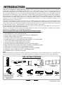
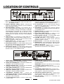
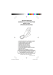
MODEL HT-395 Digital Audio Home Theater System Turns Your DVD Player Into a Home Theater Computer Compatible - Also Turns Your Computer Into a Home Theater (Cable Included) The Perfect Sound System for Your DVD Player • Just add your TV & DVD player; everything else is in the box. • Incredible surround sound, perfect for DVD viewing & enhanced TV game experience. • Front panel GAME INPUT jacks. • Dual DIGITAL inputs - COAXIAL & OPTICAL. PLEASE READ CAREFULLY BEFORE USE IB-HT395-WM-E-073003 SAFETY INSTRUCTIONS WARNING FCC NOTE TO PREVENT FIRE OR SHOCK HAZARD, DO NOT USE THE PLUG WITH AN EXTENSION CORD, RECEPTACLE OR OTHER OUTLET UNLESS THE BLADES CAN BE FULLY INSERTED TO PREVENT BLADE EXPOSURE. TO PREVENT FIRE OR SHOCK HAZARD, DO NOT EXPOSE THIS APPLIANCE TO RAIN OR MOISTURE. WARNING RISK OF ELECTRIC SHOCK DO NOT OPEN The lightning flash with arrowhead symbol, within an equilateral triangle, is intended to alert the user to the presence of uninsulated dangerous voltage within the products enclosure that may be of sufficient magnitude to constitute a risk of electric shock to persons. WARNING: TO REDUCE THE RISK OF ELECTRIC SHOCK, DO NOT REMOVE COVER (OR BACK). NO USER SERVICEABLE PAR TS INSIDE. REFER SERVICING TO QUALIFIED SERVICE PERSONNEL. The exclamation point within an equilateral triangle is intended to alert the user to the presence of important operating and maintenance (servicing) instructions in the literature accompanying the appliance. IMPORTANT SAFETY INSTRUCTIONS 1. Read these instructions. 2. Keep these instructions. 3. Heed all warnings. 4. Follow all instructions. 5. Do not use this apparatus near water. 6. Clean only with dry cloth. 7. Do not block any ventilation openings, install in accordance with the manufacturers instructions. 8. Do not install near any heat sources such as radiators, heat registers, stoves, or other apparatus (including amplifiers) that produce heat. 9. Do not defeat the safety purpose of the polarized or grounding-type plug. A polarized plug has two blades with one wider than the other. A grounding type plug has two blades and a third grounding prong. The wide blade or the third prong are provided for your safety. If the provided plug does not fit into your outlet, consult an electrician for replacement of the obsolete outlet. 10.Protect the power cord from being walked on or pinched particularly at plugs, convenience receptacles, and the point where they exit from the apparatus. 11.Only use attachments/accessories specified by the manufacturer. 12.Unplug this apparatus during lightning storms or when unused for long periods of time. 13.Refer all servicing to qualified service personnel. Servicing is required when the apparatus has been damaged in any way, such as power-supply cord or plug is damaged, liquid has been spilled or objects have fallen into the apparatus, the apparatus has been exposed to rain or moisture, does not operate normally or has been dropped. 14.This appliance shall not be exposed to dripping or splashing water and that no object filled with liquid such as vases shall be placed on the apparatus. Do not apply oil or petroleum products or solvents to any part of this set. This equipment has been tested and found to comply with the limits for a Class B digital device, pursuant to Part 15 of the FCC rules. These limits are designed to provide reasonable protection against harmful interference in a residential installation. This equipment generates, uses and can radiate radio frequency energy and, if not installed and used in accordance with the instructions, may cause harmful interference to radio communications. However, there is no guarantee that interference will not occur in a particular installation. If this equipment does cause harmful interference to radio or television reception, which can be determined by turning the equipment off and on, the user is encouraged to try to correct the interference by one or more of the following measures. - Reorient or relocate the receiving antenna. - Increase the separation between the equipment and receiver. - Connect this equipment into an outlet on a circuit different from that to which the receiver is connected. - Consult the dealer or an experienced radio/ TV technician for help. CAUTION FCC Regulations state that unauthorized changes or modifications to this equipment may void the users authority to operate it. PRECAUTIONS ON SAFETY Should any solid object or liquid fall into the Home Theater System, unplug the player, and have it checked by qualified personnel before operating it any further. ON PLACEMENT OF YOUR HOME THEATER SYSTEM Do not leave the Home Theater in a location near a heat source, or in a place subject to direct sunlight, excessively dusty rooms or rooms with very high humidity. Do not place the Home Theater system on an inclined or unstable place. Do not place anything within 1 inch of the sides or 2 inches from the back of the cabinet. The ventilation holes must not be covered for the set to operate properly and prolong the life of its components. HUMMING NOISE Cleaning the Cabinet Clean the cabinet, panel and controls with a very dry or slightly moistened soft cloth. Do not use any type of abrasive pad, scouring powder, or solvents, such as alcohol or benzene. Also be extra gentle when cleaning the lens on the center of the set. 1 This set has a cooling fan (similar to a computer). Occasionally during play, you may hear this humming, this is normal. When the main power is shut off or the set is in STANDBY mode, the cooling fan and humming will stop. IB-HT395-WM-E-073003 INTRODUCTION Thank you for purchasing this Digital Audio Home Theater System. This deluxe audio theater system turns your home into a virtual theater. In addition to the incredible surround sound of a 5.1 channel audio source, such as your current DVD player, this system also superbly enhances your other audio sources, such as a CD player, Computer, VCR, or a cassette deck. The only thing you need to add is your own TV or other devices. We have designed this system to be easy to set up, but please, review this manual before you operate your system. Please have it handy while you are setting the system up; and keep it available for future reference, or in the unlikely event that you encounter any unexpected questions or problems. We have tried to keep this manual as simple as possible. It begins with how to connect the speakers, your TV, and other optional devices. It also includes instructions on how to position the speakers for the most natural surround sound. If you follow the instructions carefully you can have the system set up in about an hour. This system was designed to provide you with many years of reliable operation with a minimum of care and maintenance. Every component in your system was perfect when it left our factory. If you experience any problem with the set up or operation of this system, please review the Trouble Shooting Guide at the end of this manual before you contact the Customer Service Department at 1-800-315-5885. (Monday - Thursday 9:00 AM - 5:00 PM, Friday 9:00 AM - 1:00 PM EST) All of the adjustable system settings have been preset at our factory for normal operation of the system. All you have to do is to sit back and enjoy the great home theater experience. Later on, you may want to change some of the optional settings like speaker volume and balance or equalizer (tone) settings. Instructions for changing them, are found later in this manual. Basic Features & Benefits of this Digital Home Theater System: 1. Dolby Digital 5.1 channel audio decoder for real home theater surround sound. 2. Preset Equalizer for truly customized sound. 3. Center & Rear speaker variable delay time setting for added realism. 4. Digital coaxial & optical input jacks. 5. TV Game / Video Camera input jacks on the front panel. 6. Includes audio inputs for DVD COAXIAL, DVD OPTICAL, TV / VCR and AUX. 7. Fully customizable individual speaker level controls. 8. Powerful subwoofer provides real BOOM in your bass. 9. Automatic decoding of Dolby Digital & Dolby Pro Logic audio signals. 10. Night mode button automatically reduces the sound level to avoid disturbing others. 11. Deluxe easy-to-use remote control with batteries included. 12. Reset button conveniently returns speaker settings to the factorys defaults. 13. Designed for easy, mistake-proof color-coded speaker setup. 14. Compatible with your computer sound system. NOTE: We recommend that you use this Home Theater System with your DVD player in order to experience the true 5.1 channel sound. However, if you do not have a DVD player, you may still use this system to get better sound from your TV set or any audio device. THIS SYSTEM CONTAINS 1 Remote Control 1 Set of Audio cables with green 3.5mm plug for Computer Connection (or other Source with 3.5mm Jack) 1 Main Unit 1 set of Audio Cables (Red & White) 1 Center Speaker 1 Yellow Video Cable 2 1 Subwoofer Speaker with Wires 1 Orange Coaxial Cable 4 Satellite Surround Speakers 5 sets of Speaker Wires 2 AAA batteries IB-HT395-WM-E-073003 TABLE OF CONTENTS Getting Started Safety Instructions-------------------------------------------------------------------------------------------------------------------------------------1 Introduction----------------------------------------------------------------------------------------------------------------------------------------------- 2 Location of Controls----------------------------------------------------------------------------------------------------------------------------------- 4,5 Remote Control Operation---------------------------------------------------------------------------------------------------------------------------6 Connections Choose Your Connection-----------------------------------------------------------------------------------------------------------------------------7 Cables Needed to Connect Components to Your Home Theater System -------------------------------------------------------- 7 Speaker System Connections: Speaker System Connections--------------------------------------------------------------------------------------------------------------------- 8,9 Speaker Positioning Information------------------------------------------------------------------------------------------------------------------ 10,11 TV Connections ---------------------------------------------------------------------------------------------------------------------------------------- 12 TV + DVD Connections ----------------------------------------------------------------------------------------------------------------------------- 13 TV + VCR Connections ----------------------------------------------------------------------------------------------------------------------------- 14 TV + VCR + Satellite Receiver Connections ------------------------------------------------------------------------------------------------15 TV + TV Game Connections ---------------------------------------------------------------------------------------------------------------------- 16 TV + Video Camera Connections ----------------------------------------------------------------------------------------------------------------17 AUX IN Connections --------------------------------------------------------------------------------------------------------------------------------- 18 Computer Connections ------------------------------------------------------------------------------------------------------------------------------ 19 Amplifier General ----------------------------------------------------------------------------------------------------------------------------------------------------20 Test Tones -----------------------------------------------------------------------------------------------------------------------------------------------21 Volume Adjustment-------------------------------------------------------------------------------------------------------------------------------------22 Listening Mode --------------------------------------------------------------------------------------------------------------------------- 23 Others EQ Mode, Night Mode, Center & Rear Speaker Sound Delay ---------------------------------------------------------------------------- 24 Trouble Shooting ------------------------------------------------------------------------------------------------------------------------ 25 Specifications ------------------------------------------------------------------------------------------------------------------------------- 26 Manufactured under license from Dolby Laboratories. Dolby and the double-D symbol are trademarks of Dolby Laboratories. Confidential Unpublished works. ©1992-1997 Dolby Laboratories, Inc. All rights reserved. 3 IB-HT395-WM-E-073003 LOCATION OF CONTROLS 1. MAIN POWER button - Press to switch the set on or off. NOTE: This button must be on in order to be able to use the REMOTE control. 2. REMOTE CONTROL SIGNAL sensor - Receives the signal from the REMOTE CONTROL (Aim the REMOTE control towards this sensor). 3. POWER/STANDBY indicator - This indicator has 2 colors: red and green (red is standby, green is on). When the set is off (standby), pressing the SOURCE or MASTER VOLUME buttons on the main unit, or pressing any button on the REMOTE CONTROL will turn the set on. The indicator will become green. Also this indicator will flash confirming that you pressed any button on the REMOTE CONTROL. 4. VIDEO IN jack - For connection of a video signal from a TV game or video camera (see details on Page 16 & 17). 5. AUDIO LEFT jack - Connect to the left channel audio output of a TV game or video camera. 6. AUDIO RIGHT jack - Connect to the right channel audio output of a TV game or video camera. 7. DVD COAXIAL indicator - For DVD COAXIAL INPUT sound use, press the SOURCE button till this lights or press the COAXIAL button on your REMOTE control. 8. DVD OPTICAL indicator - For DVD OPTICAL INPUT sound use, press the SOURCE button till this lights or press the OPTICAL button on your REMOTE control. 9. GAME indicator - For TV GAME or VIDEO CAMERA sound use, press the SOURCE button till this lights or press the GAME button on your REMOTE control. 10. TV / VCR indicator - For TV / VCR sound use, press the SOURCE button till this lights or press the TV / VCR button on your REMOTE control. 11. AUX indicator - For Auxiliary input sound use, press the SOURCE button till this lights or press the AUX button on your REMOTE control. 12. STEREO indicator - In STEREO mode, this red indicator lights up (for 2 channel sound). 13. DOLBY PRO LOGIC indicator - If a Dolby Pro Logic Signal is received, this red indicator will light. 14. DOLBY DIGITAL indicator - If a Dolby Digital Signal is received, this orange indicator will light. 15. VOLUME indicators - These indicators light up showing the level of the master volume, also each individual speakers volume. 16. MUTE indicator - In mute mode, this indicator will light. 17. SOURCE button - Press several times to select the sound input source you want: DVD COAXIAL, DVD OPTICAL, GAME, TV / VCR, or AUX. 18. MASTER VOLUME UP & DOWN control - Increases or decreases the volume level of all speakers. 1. FRONT RIGHT SPEAKER jacks - Connect the FRONT RIGHT SPEAKER to the red and black terminals. 2. FRONT LEFT SPEAKER jacks - Connect the FRONT LEFT SPEAKER to the red and black terminals. 3. CENTER SPEAKER jacks - Connect only the CENTER SPEAKER to the blue and black terminals. 4. REAR RIGHT SPEAKER jacks - Connect the REAR RIGHT SPEAKER to the grey and black terminals. 5. REAR LEFT SPEAKER jacks - Connect the REAR LEFT SPEAKER to the grey and black terminals. 6. SUBWOOFER SPEAKER jacks - Connect the SUBWOOFER SPEAKER to the green and black terminals. 7. AUX AUDIO INPUT jacks - Connect to the audio output of a tape deck or other component. 8. TV/VCR AUDIO INPUT jacks - Connect to audio output of a TV or VCR. 9. VIDEO OUT jack - Connect to your TVs video input jack. (If your TV has no VIDEO jack, you have to buy a VIDEO RF MODULATOR.) IMPORTANT: This jack is only used if you are connecting a TV GAME or VIDEO CAMERA to the set. 10. DVD VIDEO INPUT jack - Connect to your DVDs video out jack. 11. DVD COAXIAL DIGITAL INPUT jack - Connect to the COAXIAL digital audio output of a DVD player to have Dolby Digital 5.1 channel surround sound. 12. DVD OPTICAL DIGITAL INPUT jack - Connect to the OPTICAL digital audio output of a DVD Player to have Dolby Digital 5.1 channel surround sound. 13. AC LINE CORD - Connect to a 120V/60Hz AC standard wall outlet. 4 IB-HT395-WM-E-073003 LOCATION OF CONTROLS 1. ON/STANDBY button - Switches the player from STANDBY to ON or ON to STANDBY (if the main POWER of the set is on). 2. MUTE button - Instantly turns off the sound. Press again to restore the sound. 3. MASTER VOLUME UP button - Press to raise the volume level of all speakers. 4. MASTER VOLUME DOWN button - Press to lower the volume level of all speakers. 5. DVD OPTICAL button - Selects the DVD OPTICAL audio input mode. The DVD OPTICAL indicator on the front panel will light. 6. DVD COAXIAL button - Selects the DVD COAXIAL audio input mode. The DVD COAXIAL indicator on the front panel will light. 7. AUX button - Selects the AUXILIARY audio input mode. The AUX indicator on the front panel will light. 8. TV / VCR button - Selects the TV or VCR audio input mode. The TV / VCR indicator on the front panel will light. 9. GAME button - Selects the TV GAME (or VIDEO CAMERA) play mode. The GAME indicator on the front panel will light. 10. STEREO button - Press to select STEREO (2 channel) listening mode, and the STEREO indicator on the front panel will be on. 11. SURROUND button - Press to select Dolby Digital, Dolby Pro Logic (5.1 channel) audio listening mode. The sound will come out of all 6 speakers. 12. TEST TONE button - Press to activate the test tone noise function to check whether all your speakers are connected properly. 13. EQ button - Press to select different tone effects. 14. FRONT LEFT UP & DOWN VOLUME buttons - Press to adjust the individual FRONT LEFT speakers sound level. 15. FRONT RIGHT UP & DOWN VOLUME buttons - Press to adjust the individual FRONT RIGHT speakers sound level. 16. CENTER UP & DOWN VOLUME buttons - Press to adjust the individual CENTER speakers sound level. 17. REAR LEFT UP & DOWN VOLUME buttons - Press to adjust the individual REAR LEFT speakers sound level. 18. REAR RIGHT UP & DOWN VOLUME buttons - Press to adjust the individual REAR RIGHT speakers sound level. 19. SUBWOOFER UP & DOWN VOLUME buttons - Press to adjust the SUBWOOFER speakers sound level. 20. NIGHT button - Press to select NIGHT listening mode (Reduced sound level). 21. CENTER DELAY button - Press to delay the center speakers sound. 22. REAR DELAY button - Press to delay the rear speakers sound. 23. TIME UP button - Press to increase the time amount of sound delay. 24. TIME DOWN button - Press to decrease the time amount of sound delay. 25. RESET button - Press to reset all speakers outputs to the factorys default settings. 5 IB-HT395-WM-E-073003 REMOTE CONTROL OPERATION Battery Installation Remote Control Operating Range Remove the BATTERY COMPARTMENT DOOR of the REMOTE CONTROL and insert 2 size AAA alkaline batteries (included) according to the + and markings inside the BATTERY COMPARTMENT of the REMOTE CONTROL unit. Point the REMOTE CONTROL unit within 20 feet from the remote control sensor and facing the front of the HOME THEATER SYSTEM. Gently push here and slide to open the BATTERY DOOR. Insert 2 size AAA batteries as shown (included). Remember, the spring touches the battery. side of each Point the REMOTE CONTROL at the Home Theaters Front Replace the door. Make sure there is a clear path between the REMOTE CONTROL and the HOME THEATER SYSTEM so that the signal is not blocked. Tips on Battery Use Reversing polarities will damage the batteries and possibly your REMOTE. Be sure to follow polarity + and - as indicated. Do not mix different types of batteries together (Alkaline, Carbon-Zinc, Nickel-Cadmium etc.), or old batteries with new ones. When not in use for an extended period of time (over 60 days), remove the batteries to prevent possible acid leakage or corrosion resulting in possible damage to your REMOTE CONTROL. Tips on REMOTE CONTROL Operation When the batteries have become discharged, they must be disposed of in a safe manner that complies with all applicable laws. Installation of batteries should only be done by an adult (for safety). 6 The REMOTE controls operating distance may vary according to the brightness of the room. Do not point bright lights at the REMOTE CONTROL SENSOR (like laser pointers). Do not place objects between the REMOTE CONTROL unit and the REMOTE CONTROL SENSOR. Do not use this REMOTE CONTROL while simultaneously using the remote control unit of any other equipment, the signals may mix. Sometimes your TVs remote may cause an LED to flash, you can ignore this. IB-HT395-WM-E-073003 CONNECTIONS Choose Your Connection There are several ways to connect your Home Theater System. Please use the following chart to determine which connection is the best for you. Turn to the appropriate page and connect your Home Theater System. COMPONENTS CABLES NEEDED GO TO ... NOTE: This only applies if your TV has audio out jacks. TV + HOME THEATER (only) TV/DVD + HOME THEATER Video (included) Coaxial (included) Optical (not included) Page 13 TV/VCR + HOME THEATER Video (included) Audio (included) Antenna cable (not Page 14 Video (included) Audio (included) Antenna cable (not Page 15 TV/VCR + HOME THEATER + SATELLITE DIGITAL HOME THEATER SYSTEM TV + HOME THEATER + TV GAME or VIDEO CAMERA Audio (included) Page 12 included) included) Video (special, not included) Audio Page 16,17 (special, not included) TA PE RE C OR DE R/P LAY ER AM/FM TUNER or other AUX DEVICE + HOME THEATER Audio (included) Page 18,19 Cables Needed to Connect Components to Your Home Theater System The pictures below show the cables needed for the connections represented in this booklet. NOTE: Audio cables are usually sold as a bundled set, but the connection sketches in this booklet show each cable separately for better visibility. You need additional cables to connect everything shown above. Check your other equipments booklets to see what cables are needed. Yellow Video cable (included) 1 Set of Audio cables with green 3.5mm plug for Computer Connection (or other Source with 3.5mm Jack) Red & White Audio cables (included, most installations will need these) Speaker Wires (6 sets are included, and one set is attached to the back of the SUBWOOFER) 7 Orange Coaxial cable (included) Optical Cable (not included) IB-HT395-WM-E-073003 SPEAKER SYSTEM CONNECTIONS Speaker System Connections The speaker wires and connectors are color coded for easier set up. Connect the Front Left speaker to the Front Left terminals (FL). Connect the Front Right speaker to the Front Right terminals (FR). Connect the Center speaker to the Center speaker terminals (C). Connect the Rear Left speaker to the Rear Left terminals (RL). Connect the Rear Right speaker to the Rear Right terminals (RR). Connect the Subwoofer to the Subwoofer terminals (SUB). Connect the supplied speaker system using the supplied speaker cords by matching the colors of the terminals to those of the cords. IMPORTANT: Before making connections, make sure the power is off. At the rear of each supplied speaker you will find two spring type connectors in different colors: a black one (-) and a red, blue or grey one(+). (The Subwoofer does not have spring type connecting tabs at the rear, only a set of black & green speaker wires from its back.) QUICK SETUP DIAGRAM IMPORTANT! 1. This Home Theater only improves the sound of your DVD system, it works excellently for Dolby Digital & Dolby Pro Logic audio signals only when your DVDs AUDIO OUTPUT is set to DIGITAL mode. 2. DTS signals can not be decoded by this set. NOTE In your package you will find 6 sets of colored speaker wire pairs for connecting your Home Theater to the 6 different speakers: 1 green and black pair of wires for the subwoofer which comes out of the back of the subwoofer (12 1/2 feet long). 2 grey and black pairs of wires (26 feet long) for connecting the rear speakers with grey and black terminals. 1 blue and black pair of wires (13 feet long) for the center speaker with blue and black terminals. 2 red and black pairs of wires (13 feet long) for the front speakers with red and black terminals. 8 IB-HT395-WM-E-073003 SPEAKER SYSTEM CONNECTIONS Tips for connecting the speaker wires To avoid short-circuiting the speakers Make sure the stripped end of each speaker wire does not Push and hold the Speaker terminal tab down to insert each wire. Release the tab to lock the wire into the terminal. Make sure the wire is fully inserted, but the insulation is not covering the inserted part of the speaker wires. touch another speaker terminal or the stripped end of another speaker wire. Examples of poor connection of the speaker wires Stripped speaker wire is touching another speaker terminal. Make sure not even 1 strand of wire touches the other wire! • Stripped wires are touching each other due to excessive removal of insulation. Do not allow the above to happen on your set or speakers. NOTE: Be sure to match the speaker wire to the appropriate terminal on the components: (+) to (+) (color), and (-) to (-) (black). If the wires are reversed, the sound will be distorted and will lack some tones. Follow the color codes of each speaker. 9 IB-HT395-WM-E-073003 SPEAKER POSITIONING INFORMATION Your system is supplied with 5 compact sized satellite speakers and one large subwoofer. The satellite speakers reproduce only the mid range and higher frequencies. All of the low frequency (bass) sounds are produced by the subwoofer. Proper positioning and placement of the speakers is important in order to provide the best surround sound experience. We understand that due to the size and shape of your listening room, and the location of your furniture, you may not be able to set up the speakers exactly as per these diagrams. However these simple guidelines will help you maximize your home theater experience. Your Usual Seat Note the speaker levels are preset at the factory and most people will not need to fine tune the sound of each speaker. We suggest you skip this part at first. Later on you can adjust the sound level of each individual speaker. See Page 20. Although all 5 satellites are of the same size, the speakers inside POSITION ALL 5 SPEAKERS APPROXIMATELY AT THE SAME DISTANCE FROM YOUR LISTENING POSITION. POSITION THE SUBWOOFER AS BELOW. the cabinets are different. The speaker terminals on the back of the cabinets are color-coded, as are the speaker wires and the speaker terminals on the back of the main unit. Refer to the connection diagram on page 8. Be sure you are using the correct satellite speaker in each location, front, rear and center. Please follow the colors for best results. For best surround sound effects, all 5 of the satellite speakers should be approximately at the same distance from your usual listening position. POSITION THE SPEAKERS LIKE THIS FOR OPTIMAL LISTENING EXPERIENCE All 4 satellite speakers and the center speaker should be placed approximately the same distance from your listening position. The center speaker should be placed directly above (or below) the TV set. Left and right front speakers should be approximately at the same height as the center speaker. The rear speakers should be either in line with, or behind your listening position, approximately at ear level, or slightly above. The subwoofer should be on the floor near the TV, or in any corner, with the front facing your listening position. All speakers must be visible. Do not hide them behind curtains, furniture, etc., as this will affect the sound. 10 IB-HT395-WM-E-073003 SPEAKER POSITIONING INFORMATION • The center speaker, as well as the other 4 satellite speakers, can be positioned either vertically or horizontally. • The left front, right front, and center speakers should be placed at approximately the same height. The center speaker reproduces most of the dialog spoken by the actors on the TV screen, therefore it should be placed either directly above or below the center of the TV set. Once you position the center speaker, try to position the left front and right front speakers at the same height. It is not recommended to place any of the satellite speakers on the floor. Many people prefer to place the center speaker horizontally above the TV set. • The left rear and right rear speakers can be placed in line with your listening position or behind your listening position. Ideally they should be placed slightly above your ear level when you are seated in your normal listening position. • We have provided 2 keyhole openings on the backs of all the satellite speakers that allow the satellite speakers to be wall mounted in either a vertical or horizontal position. • The subwoofer will provide the most dramatic bass effects (low frequency sounds like explosions and thunder) when it is placed on the floor. Do not place the subwoofer on a stand or table. The subwoofer should be placed in the front of the room so that it is facing towards your listening position. It can be placed on either side of the TV or even in the corner of the room, as far away as the cable will allow. The bass sounds from the subwoofer are non-directional. You will not really be able to tell where the bass is coming from. • LONG ROOMS - In case your room is unusually long, you may buy speaker wires from your dealer for adding wire length to your speakers. Be careful not to allow the plus + and minus - wires to touch each other. Use electrical tape or plastic connectors to insulate the wires from each other. 11 IB-HT395-WM-E-073003 TV CONNECTIONS (For better sound from TV shows) Home Theater System + TV (if your TV has Audio Output jacks) CONNECT ALL SPEAKERS AS SHOWN ON PAGE 8 (OR THE QUICK SETUP DIAGRAM SHEET). RED & WHITE AUDIO CABLES (INCLUDED) NOTE: If your TV does not have audio output jacks, it can not be used to improve your TVs sound. NOTE: On some TVs, these jacks are in the front, or your TV may not have these jacks. If you have a cable box or satellite receiver, you can connect the receiver AUDIO OUTPUT directly to your TV/VCR AUDIO INPUT on the back of the HOME THEATER SYSTEM. 1. Connect the 5 satellite speakers and subwoofer as shown on Page 8 (or the QUICK SETUP DIAGRAM packed with the set). 2. Insert the stereo audio cables (included) into the TV / VCR AUDIO INPUT L (left=white) and R (right=red) j a c k s on the back of your HOME THEATER SYSTEM, and into the corresponding AUDIO OUT jacks on your TV, this will allow your TVs sound to play through your HOME THEATER SYSTEM (If your TV set has AUDIO OUTPUT jacks). NOTE: Your TVs sound will come out of the 2 front speakers plus the subwoofer since the default setting for the sound output is the same as the audio source from the TV (2 channel, STEREO). For Dolby Pro Logic (5.1 channel) sound reproduction, press the SURROUND button. The sound will come out of all 5 speakers plus the subwoofer. NOTE: On some TVs, you may have to activate the audio out jacks of your TV. See your TVs booklet. NOTE: If the signal of your TV is not a true STEREO signal, even though it has stereo output jacks, when you press the SURROUND button, the sound may not come out from all 5 speakers. This is normal. NOTE: Some TVs may not allow the Home Theater to play all 5 speakers if the audio output level of the TV is too low. 3. Insert the AC power cord into an AC outlet. 4. Press the POWER button on the main unit (not the REMOTE) to turn on the main power of the set. Next press the ON/STANDBY button on the REMOTE to turn the set on (or off). 5. Press the SOURCE button on the main set several times till the TV/VCR indicator lights. 6. Go to Page 20 for detailed instructions. NOTE: Your cable or antenna connection to your TV are not touched with this connection. Leave your antenna cable to your TV as you normally would. No changes will be made to your current antenna connections. 12 IB-HT395-WM-E-073003 TV + DVD CONNECTIONS Home Theater System + TV + DVD Player NOTE: Some newer TV sets have several VIDEO INPUT jacks. You may use one of these for your DVD player and the others for connecting to the VIDEO OUT jacks of the component. If your set is older and only has a single VIDEO INPUT jack, you may buy a switch box to change video signal from DVD to game, etc. 1. Insert the COAXIAL cable (included) or OPTICAL cable (not included) into the COAXIAL or OPTICAL DIGITAL INPUT jack on the back of your HOME THEATER SYSTEM, and into the DIGITAL (COAXIAL or OPTICAL) jack on your DVD player, this will allow your DVDs Dolby Digital Audio sound to play through your HOME THEATER SYSTEM. NOTE: For a Dolby Digital recorded DVD disc, the sound will come out of all 5 speakers plus the subwoofer. For a Stereo DVD disc (2 channel), the sound will only come out of the 2 front speakers plus the subwoofer. This set will decode and automatically play back whatever sound system was recorded on the DVD or audio disc. To manually change stereo (2 channel) audio to Dolby Pro Logic, press the SURROUND button. The sound will come out of all 5 speakers plus the subwoofer. NOTE: Make sure your DVDs AUDIO OUTPUT is set to DIGITAL. NOTE: DTS signals can not be decoded by this set. 2. Insert the video cable into the VIDEO OUT jack on the back of your DVD player, and into the VIDEO IN jack on the back of your HOME THEATER SYSTEM. 3. 4. Insert the video cable into the VIDEO IN jack on your TV, and into the VIDEO OUT jack on the back of your HOME THEATER SYSTEM. Insert the AC power cord into an AC outlet. 5. Press the POWER button on the main unit (not the REMOTE) to turn on the main power of the set. Next press the ON/STANDBY button on the REMOTE to turn the set on (or off). 6. Press the SOURCE button on the main set several times till the COAXIAL or OPTICAL indicator lights. 7. Make sure your DVD player is on and follow your DVD players instructions. 8. Go to Page 20 for detailed instructions. NOTE: Your cable or antenna connection to your TV are not affected with this connection. Leave your antenna cable connected to your TV as you normally would. No changes will be made to your current antenna connections. 13 IB-HT395-WM-E-073003 TV + VCR CONNECTIONS Home Theater System + TV + VCR CONNECT ALL SPEAKERS AS SHOWN ON PAGE 8 (OR THE QUICK SETUP DIAGRAM SHEET). 1. Insert the stereo audio cables (included) into the TV/VCR AUDIO INPUT L (left=white) and R (right=red) jacks on the back of your HOME THEATER SYSTEM, and into the corresponding AUDIO OUT jacks on your VCR, this will allow your VCRs sound to play through your HOME THEATER SYSTEM. NOTE: Your VCRs sound will come out of the 2 front speakers plus the subwoofer since the default setting for the sound output is the same as the audio source from the VCR (2 channel, STEREO). For Dolby Pro Logic (5.1 channel) sound reproduction, press the SURROUND button on the REMOTE. The sound will come out of all 5 speakers plus the subwoofer. NOTE: Some VCRs may not allow the Home Theater to play all 5 speakers if the audio output level of the VCR is too low. 2. Connect your VCR to your TV using a coaxial antenna cable (probably already connected), your VCRs picture will go to your TV through the antenna connection. 3. Connections of your other antenna cables are not changed when you add your HOME THEATER SYSTEM. 4. Insert the AC power cord into an AC outlet. 5. Press the POWER button on the main unit (not the REMOTE) to turn on the main power of the set. Next press the ON/STANDBY button on the REMOTE to turn the set on (or off). 6. 7. Press the SOURCE button several times till the TV/VCR indicator lights. Make sure your VCR is on and follow your VCRs instructions. 8. Go to Page 20 for detailed instructions. 14 IB-HT395-WM-E-073003 TV + VCR + SATELLITE RECEIVER CONNECTIONS Home Theater System + TV + VCR + Satellite NOTE: On some TVs, this jack is in the front. CONNECT ALL SPEAKERS AS SHOWN ON PAGE 8 (OR THE QUICK SETUP DIAGRAM SHEET). 1. Follow the above connection diagram and check if you have these items. If your VCR has AUDIO OUT jacks, you may connect your VCR to your HOME THEATER as shown. NOTE: Your VCRs sound will come out of the 2 front speakers plus the subwoofer since the default setting for the sound output is the same as the audio source from the VCR (2 channel, STEREO). For Dolby Pro Logic (5.1 channel) sound reproduction, press the SURROUND button. The sound will come out of all 5 speakers plus the subwoofer. NOTE: Some VCRs may not allow the Home Theater to play all 5 speakers if the audio output level of the VCR is too low. 2. Connect your VCR to your TV using a coaxial antenna cable (probably already connected), your VCRs picture will go to your TV through your existing antenna connection. 3. Use an antenna cable to connect the antenna output on the satellite receiver to the antenna input on the VCR the same as you have it connected now. This audio HOME THEATER SYSTEM does not change any antenna connections. 4. Insert the AC power cord into an AC outlet. 5. 6. Press the POWER button on the main unit (not the REMOTE) to turn on the main power of the set. Next press the ON/STANDBY button on the REMOTE to turn the set on (or off). Press the SOURCE button several times till the TV/VCR indicator lights. 7. Make sure your VCR is on and follow your VCRs instructions. 8. Go to Page 20 for detailed instructions. 15 IB-HT395-WM-E-073003 TV + TV GAME CONNECTIONS Home Theater System + TV + TV Game NOTE: Your TV GAME may have a special cable for connections. This diagram is only for illustration. CONNECT ALL SPEAKERS AS SHOWN ON PAGE 8 (OR THE QUICK SETUP DIAGRAM SHEET). (Optical cable is not included) 1. 2. 3. Insert the stereo audio cables into the AUDIO INPUT L (left=white) and R (right=red) jacks on the FRONT of your HOME THEATER SYSTEM, and into the corresponding AUDIO OUT jacks on your TV GAME, this will allow your TV GAMEs sound to play through your HOME THEATER SYSTEM. NOTE: Your TV GAME may also have an optical jack for sound output. If you have an optical cable, you may connect your TV GAMEs output to the HOME THEATER by using the optical cable for better sound (optical cable is not included). Insert the yellow video cable (included with your TV GAME) into the VIDEO IN jack on the FRONT of your HOME THEATER SYSTEM, and into the VIDEO OUT jack on your TV GAME. Insert another video cable into the VIDEO OUT jack on the back of your HOME THEATER SYSTEM, and into the VIDEO IN jack on your TV. NOTE: Your TV GAMEs sound will come out of the 2 front speakers plus the subwoofer since the default setting for the sound output is the same as the audio source from the TV GAME (2 channel, STEREO). For Dolby Pro Logic (5.1 channel) sound reproduction, press the SURROUND button on the REMOTE. The sound will come out of all 5 speakers plus the subwoofer. NOTE: Some TV GAME may not allow the Home Theater to play all 5 speakers if the audio output level of the TV GAME is too low. 4. Insert the AC power cord into an AC outlet. 5. Press the POWER button on the main unit (not the REMOTE) to turn on the main power of the set. Next press the ON/STANDBY button on the REMOTE to turn the set on (or off). 6. Press the SOURCE button several times till the GAME indicator lights. NOTE: In case you use an OPTICAL cable for sound, press OPTICAL on your remote for the TV GAME sound. 7. Make sure your TV GAME is on and follow your TV GAMEs instructions. 8. Go to Page 20 for detailed instructions. 16 IB-HT395-WM-E-073003 TV + VIDEO CAMERA CONNECTIONS Home Theater System + TV + Video Camera NOTE: Your VIDEO CAMERA may have a special cable (with a triple 3.5mm plug on one side) for connections. This diagram is only for illustration. CONNECT ALL SPEAKERS AS SHOWN ON PAGE 8 (OR THE QUICK SETUP DIAGRAM SHEET). 1. Insert the stereo audio cables into the AUDIO INPUT L (left=white) and R (right=red) jacks on the FRONT of your HOME THEATER SYSTEM, and into the corresponding AUDIO OUT jacks on your VIDEO CAMERA, this will allow your CAMERA VIDEOs sound to play through your HOME THEATER SYSTEM. (NOTE: Many video cameras have special plugs on one side to connect to your camera.) 2. Insert the video cable (included with your VIDEO CAMERA) into the VIDEO IN jack on the FRONT of your HOME THEATER SYSTEM, and into the VIDEO OUT jack on your VIDEO CAMERA. (NOTE: Your video camera may have a 3.5mm triple jack, consult your cameras booklet for details.) 3. Insert the video cable (included) into the VIDEO OUT jack on the back of your HOME THEATER SYSTEM, and into the VIDEO IN jack on your TV. NOTE: Your VIDEO CAMERA sound will come out of the 2 front speakers plus the subwoofer since the default setting for the sound output is the same as the audio source from the VIDEO CAMERA (2 channel, STEREO). For Dolby Pro Logic (5.1 channel) sound reproduction, press the SURROUND button. The sound will come out of all 5 speakers plus the subwoofer. NOTE: Some video cameras may not allow the Home Theater to play all 5 speakers if the audio output level of the video camera is too low. 4. Insert the AC power cord into an AC outlet. 5. Press the POWER button on the main unit (not the REMOTE) to turn on the main power of the set. Next press the ON/STANDBY button on the REMOTE to turn the set on (or off). Press the SOURCE button several times till the GAME indicator lights. (This setting is either for a Video Camera or a TV Game.) 6. 7. Make sure your VIDEO CAMERA is on and follow your VIDEO CAMERAs instructions. 8. Go to Page 20 for detailed instructions. 17 IB-HT395-WM-E-073003 AUX IN CONNECTIONS CONNECT ALL SPEAKERS AS SHOWN ON PAGE 8 (OR THE QUICK SETUP DIAGRAM SHEET). Illustration is showing some possible connections. You can only connect ONE of these components to the AUX INPUT jacks of your HOME THEATER SYSTEM (AUX stands for Auxiliary). You can hear the sound of any one of these devices through your HOME THEATER SYSTEM if you connect the proper cables. 1. Insert the audio cables into the AUX OUTPUT L (left=white) and R (right=red) jacks of your stereo system, such as a TAPE RECORDER PLAYER into the corresponding AUX INPUT AUDIO jacks on your HOME THEATER. This will enable you to hear your components system through your HOME THEATER SYSTEM. 2. You may also use the green 3.5mm plug and cable (included) to connect your CD PLAYER, RADIO or other device that has a 3.5MM stereo jack to your HOME THEATER SYSTEM. NOTE: Your audio devices sound will come out of the 2 front speakers plus the subwoofer since the default setting for the sound output is the same as the audio source from the device (2 channel, STEREO). For Dolby Pro Logic (5.1 channel) sound reproduction, press the SURROUND button. The sound will come out of all 5 speakers plus the subwoofer. NOTE: If the signal of your device (such as a CABLE/SAT BOX or some STEREO TVs) is not a true STEREO signal, even though it has stereo output jacks, when you press the SURROUND button, the sound may not come out from all 5 speakers. This is normal. NOTE: Some devices may not allow the Home Theater to play all 5 speakers if the audio output level of the device is too low. 3. Press the POWER button on the main unit (not the REMOTE) to turn on the main power of the set. Next press the ON/STANDBY button on the REMOTE to turn the set on (or off). 4. Press the SOURCE button several times till the AUX indicator lights. 5. 6. Make sure your AUX IN component is on and follow your components instructions. Go to Page 20 for detailed instructions. 18 IB-HT395-WM-E-073003 COMPUTER CONNECTIONS CONNECT ALL SPEAKERS AS SHOWN ON PAGE 8 (OR THE QUICK SETUP DIAGRAM SHEET). ONE SET OF AUDIO CABLES WITH 3.5MM PLUG IS INCLUDED 1. Insert the green 3.5mm audio plug of the AUDIO cable (included) into the PC AUDIO OUT jack of your PC, and insert the AUX INPUT L (left = white) and R (right = red) plugs into the corresponding AUX INPUT jacks on the back of your HOME THEATER. This will enable you to hear your computers music through your HOME THEATER SYSTEM. 2. Press the POWER button on the main unit (not the REMOTE) to turn on the main power of this set, next press the ON/STANDBY button on the REMOTE to turn the set on (or off). 3. Press the SOURCE button several times till the AUX indicator lights. NOTE: Your computers sound will come out of the 2 front speakers plus the subwoofer since the default setting for the sound output is the same as the audio source from the computer (2 channel, STEREO). For Dolby Pro Logic (5.1 channel) sound reproduction, press the SURROUND button. The sound will come out of all 5 speakers plus the subwoofer. NOTE: If the signal of your computer is not a true STEREO signal, even though it has stereo output jack, when you press the SURROUND button, the sound may not come out from all 5 speakers. This is normal. NOTE: Some computers may not allow the Home Theater to play all 5 speakers if the audio output level of the computer is too low. 4. Make sure your computer is on and follow your computers instructions. 5. Go to Page 20 for other detailed instructions. 19 IB-HT395-WM-E-073003 AMPLIFIER General 1 Press the POWER button on the front panel of the main unit to turn the main power on, press SOURCE or MASTER VOLUME buttons on the main unit, or any button on the REMOTE control to turn the set on. Make sure the POWER/STANDBY indicator is lit in green. NOTE: The POWER/STANDBY indicator has 2 colors: red and green (green is on, red is standby). When the set is off (standby), pressing the SOURCE or MASTER VOLUME buttons on the main unit, or pressing any button on the REMOTE CONTROL will turn the set on. The indicator will become green. Also this indicator will flash confirming that you pressed any button on the REMOTE CONTROL. 2 Press the SOURCE button on the front panel of the main unit repeatedly to select one of the input sources, or press the individual COAXIAL, OPTICAL, GAME, TV/VCR or AUX buttons on the REMOTE to select the audio input source. The corresponding indicator will light. 3 For volume adjustments, press each individual speakers volume control buttons: + raises the volume lowers the volume Follow this step to adjust the other speakers as well. Or you may press the MASTER VOLUME buttons to raise or lower all speakers volumes at the same time. For details, see page 21. 4 To select the listening mode, press the SURROUND or STEREO button on the REMOTE CONTROL. NOTE: This set will decode and automatically play back whatever sound system was recorded on the DVD or audio disc. For a Dolby Digital 5.1 channel audio source, the sound will come out of all 5 speakers plus the subwoofer; for a Dolby Digital 2.1 channel or other stereo audio source, the sound will only come out of the 2 front speakers plus the subwoofer. To manually change a stereo (2 channel) audio to Dolby Pro Logic, press the SURROUND button. The sound will come out of all 5 speakers plus the subwoofer. 5 For different preset equalizers (tone selections) and sound effects, press the EQ, NIGHT, DELAY TIME buttons on the REMOTE to select the tones (frequency response) you like best (see details on page 24). 6 To momentarily shut off the sound, press the MUTE button. The red MUTE indicator will light. Press the MUTE button again or press the MASTER VOLUME buttons to restore the sound. 20 IB-HT395-WM-E-073003 AMPLIFIER Test Tones You can check whether your speakers are connected correctly by using the TEST TONE button. 1 Press the POWER button on the front panel of the main unit to turn the main power on, press SOURCE or MASTER VOLUME buttons on the main unit, or any button on the REMOTE control to turn the set on. Make sure the POWER/STANDBY indicator is lit in green. 2 Press the TEST TONE button on the REMOTE. 3 You will hear a test tone (actually some blank noise similar to a steady ocean wave) from the FRONT LEFT (FL), CENTER (C), FRONT RIGHT (FR), REAR RIGHT (SR) and REAR LEFT (SL) speakers in sequence. The VOLUME indicators on the front panel will show the corresponding speaker which is being tested. NOTE: If the set is in STEREO mode (the red STEREO indicator is on), you will only hear a test tone from the FRONT LEFT (FL) and FRONT RIGHT (FR) speakers. To change the set from STEREO to Dolby Pro Logic or Dolby Digital mode, press the SURROUND button on the REMOTE. RESET BUTTON Pressing this button on the remote control will reset all 5 satellite speakers and the subwoofer to their default settings and will also reset the preset equalizer to the normal position. NOTE: You can stop the test tone by pressing any button on the REMOTE control, or by pressing the SOURCE or MASTER VOLUME buttons on the main unit. 4 After your test, you may play the theater system or adjust the individual volume controls while playing any music or movie and then retest the levels if you like. You may then adjust each speakers volume level by pressing the VOLUME controls of the individual speakers, so that from your center listening position, they all have approximately the same sound level. To restore all speaker levels to their factory defaults, press the RESET button. 21 IB-HT395-WM-E-073003 AMPLIFIER Volume Adjustment 1 To adjust the master volume (Change all the speakers volume settings at the same time), press the MASTER VOLUME buttons on the main unit or on the REMOTE to decrease or increase the master volume level. raises the volume lowers the volume The VOLUME indicator on the front panel will show the corresponding volume level as progressively lit LED lamps: VOLUME As the volume increases, more LED lamps will light up. VOLUME Minimum volume level (no LED lit). VOLUME Maximum volume level (all LEDs lit). 2 To adjust the individual speakers volume: NOTE 1: Every time you turn the set on, the MASTER VOLUME will go back to the factorys default settings; and whenever you press the SOURCE button on the main unit or one of the source buttons on the REMOTE control (COAXIAL, OPTICAL, GAME, TV/VCR or AUX), the MASTER VOLUME will go back to the factorys default settings. This avoids sudden very loud sounds from startling you. Press the FRONT LEFT VOLUME CONTROL + or button on the REMOTE to adjust the sound level of the FRONT LEFT SPEAKER. Do the same to adjust the volume of the other individual speakers: FRONT RIGHT SPEAKER, CENTER SPEAKER, REAR LEFT SPEAKER, REAR RIGHT SPEAKER and SUBWOOFER SPEAKER. VOLUME The default volume control VOLUME NOTE 2: Pressing the VOLUME CONTROL buttons of the individual speaker could only fine tune the volume of the individual speaker. Press the MASTER VOLUME buttons on the main unit or on the REMOTE to decrease or increase the master volume level. Increased volume level VOLUME Decreased volume level 22 IB-HT395-WM-E-073003 LISTENING MODE Dolby Digital (also known as AC-3 or Dolby 5.1) surround sound system delivers a realistic and dynamic sound similar to the latest movie theaters. All five speakers and subwoofer must be connected for correct Dolby Digital Surround Sound reproduction. Each channel plays its own unique role in providing the proper sound. Front left, center and front right speakers join rear left and rear right to reproduce high, mid and bass frequencies in separate five full-range channels of surround sound. Bass rumble, explosions and low frequency effects you feel are heard through the subwoofer. Most DVD movie discs have been recorded in Dolby Digital surround sound mode. This set will automatically select the correct Dolby mode according to source provided. 1 Press the SOURCE button on the front panel of the main unit repeatedly to select one of the input source, or press the COAXIAL, OPTICAL, GAME, TV/VCR or AUX button on the REMOTE to select your required audio input source directly. The corresponding indicator will light. NOTE: This set will decode and automatically play back whatever sound system was recorded on the DVD or audio disc. For a Dolby Digital 5.1 channel recorded DVD disc, the orange Dolby Digital indicator will be on and sound will come out of 5 speakers plus the subwoofer. For a Stereo DVD disc (Dolby Digital 2 channel), both the orange Dolby Digital and red stereo indicators will be on and the sound will only come out of the 2 front speakers plus the subwoofer. For other stereo audio source, the red STEREO indicator will be on, and the sound will only come out of the 2 front speakers plus the subwoofer. To manually change a stereo (2 channel) audio to Dolby Pro Logic, press the SURROUND button. The sound will come out of all 5 speakers plus the subwoofer. (However the REAR speakers may be lower because this is not the natural way the sound was recorded. This is normal.) 2 Press the SURROUND button on the REMOTE control to select 5.1 channel sound format. Press the STEREO button to select the stereo mode. The chart on the left shows different indicators for different signals in different modes. NOTE: If the input signal is Dolby Digital sound format, the orange DOLBY DIGITAL indicator will be on, two listening modes can be selected: Dolby Digital or STEREO. Try each to see what you prefer. Some programs may sound better in the STEREO mode. A. If a Dolby Digital 2.1 channel sound input signal is received, both the Stereo and Dolby Digital indicators will be on. Sound will only come out of 2 front speakers plus the subwoofer. B. If a stereo sound signal is received from AUX, only the STEREO indicator will be on. Sound will come out of 2 front speakers plus the subwoofer. 23 IB-HT395-WM-E-073003 OTHERS EQ Mode You can press EQ button repeatedly on the REMOTE CONTROL to choose from 7 different tone effects: Standard, classical, jazz, rock, pop, ballad & dance. The volume indicators will change according to different EQ mode as follows: Standard Classical First LED lights Jazz Second LED lights Rock Middle LED lights Pop 4th LED lights Ballad Last LED lights First 2 LEDS light Dance NIGHT Mode 2nd & 3rd LEDS light NOTE: Each type of equalizer setting is indicated by different indicators lighting up. This reduces the speaker output level to avoid annoying others with loud sounds. NOTE: This function is only working when the set is in DVD digital Dolby AC-3 mode. Pressing the NIGHT button on the REMOTE CONTROL to choose night mode. The signal dynamic range will be decreased by 10 dB. All the volume indicators on the front panel will light instantly and go back to the original mode after 2 seconds. All indicators light up The original volume level Press the NIGHT button again to cancel the night mode. The signal dynamic range will resume to the original value. All the VOLUME INDICATORS on the front panel will go off instantly and go back to the original mode after 2 seconds. CENTER / REAR SPEAKERS SOUND DELAY Some rooms will reproduce the sound effects of a theater if several of the speakers have a slight time delay. This set allows you to adjust the time delay of the CENTER & REAR speakers by using the remote control. NOTE: 1 millisecond (1/1000 of a second) equals approximately 1 foot of sound travel. To set the sound delay of the CENTER or the REAR speaker, press the CENTER or REAR delay button, then press the or button. A. When in Dolby Digital 5.1 channel mode: For the Rear speakers, the factorys default setting is 6ms, the delay allowance is 0 ~ 15ms. Each press will reduce or increase a 3ms delay. For the Center speaker, the factorys default setting is 0 ms, the delay allowance is 0 ~ 5ms. Each press will reduce or increase a 1ms delay. B. When in Dolby Pro Logic mode, you can only adjust the delay time of the rear speakers, the factorys default setting is 21ms and the delay allowance is 15 ~ 30ms. Each press will increase or decrease a 3ms delay. 24 IB-HT395-WM-E-073003 TROUBLE SHOOTING Remedy Symptom No power 1. Is the power cord firmly plugged into the power outlet? Insert the AC power plug securely into the power outlet. Make sure your outlet has power, you can check this by plugging a lamp into the outlet to see if works. 2. One of the safety mechanisms may be operating. In this event, unplug the player from the power outlet briefly and then plug it in again to reset the set. Your DVD player has no picture Make sure your DVDs video cable is plugged into your TV set. This Home Theater only improves the sound of your DVD player, it does not affect the video at all. Also adjust your TVs VIDEO INPUT. No sound or only a very low-level sound is heard. Distorted sound. The REMOTE CONTROL unit does not work. 1. Check that the speakers and components are connected securely and correctly (see Page 8, 9). Also check speaker volume (see Page 22). 2. Make sure your source (DVD or other) is plugged in and operating. Also check that components booklet, maybe you need adjust that component. 3. Make sure that you have selected the correct source on the system (DVD or other). 4. Ensure that the input settings for the TV and stereo system are correct. 5. Adjust the master volume settings on the HOME THEATERs remote. 6. Ensure the MUTE button is not pressed on the HOME THEATER remote (If yes, press the MUTE button again, the MUTE indicator will go off). 7. The audio or speaker connecting wires are damaged. Replace them with new ones. 1. Check if the batteries are installed with the correct polarities ( + and ). 2. If the batteries are weak or dead, replace them with new ones (size AAA). 3. Point the remote control unit at a distance of less than 20 feet from the main unit of the HOME THEATER system. 4. Remove any obstacles between the remote control unit and remote control sensor. 5. If the battery terminals are dirty or corroded, clean them with sandpaper. No buttons operate (on the main unit and / or the REMOTE CONTROL unit). Press the POWER button on the MAIN UNIT to turn the set ON. Then press the ON/STANDBY button on the REMOTE. The HOME THEATER may not be operating properly due to lightning, static electricity, or some other external factors. Reset the player by disconnecting the power plug and then re-connecting it before calling customer service. Humming noise is heard even if the set stopped. This is a normal sound the cooling fan inside makes. This will stop if the power is off. Press the ON/STANDBY button on the REMOTE to put the set in STANDBY mode. The left and right sounds are unbalanced or reversed. 1. Check that the speakers and components are connected correctly and securely. 2. Adjust front balance by pressing the volume controls of the left and right speakers on the REMOTE (see Page 22). Loud hum or noise is heard. 1. Check that the speakers and components are connected securely. 2. Insert all wires firmly, follow the setup pages starting on Page 7. The surround effect is difficult to hear when playing a Dolby Digital sound track. Depending on the digital sound input, the output signal may at times be monaural or stereo even if the main sound track is recorded in Dolby Digital format. The sound comes from the 2 front speakers and subwoofer only. The input audio signal is stereo. This set will decode and automatically play back sound in the format that was originally input. This is normal. Press the SURROUND button on your remote to hear all speakers. During DVD play, the STEREO indicator is on. If your DVD disc was recorded with PCM, this is normal. Press the SURROUND button. No sound is heard from the center speaker. 1. Make sure the Center speakers volume is set to a normal level (see Page 22). 2. Adjust the center speaker volume by pressing the volume control buttons of the center speaker on the REMOTE (see Page 22). 3. If you are listening to a stereo broadcast, only 2 front speakers (plus the subwoofer) will have sound. No sound or only a very low-level sound is heard from the rear speakers. 1. If you are playing a stereo CD, only the FRONT speakers plug the subwoofer will have sound. 2. Make sure the volume control of the rear speakers are set to normal levels (see Page 22). 3. Adjust the rear speakers volume by pressing both of the REAR the VOLUME control buttons on the REMOTE. 4. Check if the input signal is DTS signal. DTS signals can not be decoded by this set. The system does not operate properly. Double check if input & output jacks were inserted properly. Also ask a friend to help you before calling customer service. Slight delay when switching from digital to analog input. This is normal, as the set tries to detect stereo or 5.1 channel signals. The NIGHT button has no function. This button is only working when the set is in DVD digital Dolby AC-3 mode. 25 IB-HT395-WM-E-073003 SPECIFICATIONS General Power requirements ----- AC 120V, 60Hz Power consumption ------55W Main Unit Dimensions ---14 1/8 x 10 1/2 x 2 1/ 8 inches / 36.0 X 26.6 X 5.4 cm Weight ---------------------- 7.23 lbs / 3.25 kg Audio Power Outputs Total output power: 100 Watts at Maximum Distortion 0.06% @ reference output Remote Operating Range Within 20 feet between the main unit and the remote. Speakers Subwoofer ------------------ Dimensions: 7 1/16 x 10 5/8 x 9 inches / 180 X 270 X 245 mm Weight: 6.13 lbs / 2.78 kg Front Left ------------------- Dimensions: 4 1/ 4 x 3 1/2 x 4 3/8 inches / 101 X 90 X 110 mm Weight: 0.88 lb / 0.4 kg Center ----------------------- Dimensions: 4 1/4 x 3 1/2 x 4 3/8 inches / 101 X 90 X 110 mm Weight: 0.88 lb / 0.4 kg Front Right ----------------- Dimensions: 4 1/4 x 3 1/2 x 4 3/8 inches / 101 X 90 X 110 mm Weight: 0.88 lb / 0.4 kg Rear Left ------------------- Dimensions: 4 1/4 x 3 1/2 x 4 3/8 inches / 101 X 90 X 110 mm Weight: 0.71 lb / 0.32 kg Rear Right ----------------- Dimensions: 4 1/4 x 3 1/2 x 4 3/8 inches / 101 X 90 X 110 mm Weight: 0.71 lb / 0.32 kg DURABRAND reserves the right to make design and specification changes for product improvement. PROTECT YOUR FINE FURNITURE! WE RECOMMEND A CLOTH OR OTHER PROTECTIVE MATERIAL BE PLACED UNDER THE SET WHEN PLACING IT ON A SURFACE WITH A NATURAL OR LACQUER FINISH. For customer service of this Durabrand product Visit Our Website: http://www.lenoxx.com or Dial 1-800-315-5885 (MONDAY-THURSDAY 9:00 AM - 5:00 PM, FRIDAY 9:00 AM - 1:00 PM EST) or Write to: LENOXX ELECTRONICS CORP. 2 GERMAK DRIVE CARTERET, N.J. 07008 © 2003 LENOXX ELECTRONICS CORP. MADE & PRINTED IN CHINA 26 IB-HT395-WM-E-073003